
Electrochemical degradation of a C6-perfluoroalkyl substance (PFAS) using a simple activated carbon cathode†
Diana
Ackerman Grunfeld
a,
Adele M.
Jones
a,
Jun
Sun
b,
Song Thao
Le
a,
Russell
Pickford
c,
Qingguo
Huang
 d,
Michael
Manefield
a,
Naresh
Kumar
b,
Matthew J.
Lee
a and
Denis M.
O'Carroll
*a
d,
Michael
Manefield
a,
Naresh
Kumar
b,
Matthew J.
Lee
a and
Denis M.
O'Carroll
*a
aSchool of Civil and Environmental Engineering, Water Research Centre, The University of New South Wales, Sydney, NSW 2052, Australia. E-mail: d.ocarroll@unsw.edu.au
bSchool of Chemistry, The University of New South Wales, Sydney, NSW 2052, Australia
cBioanalytical Mass Spectrometry Facility, Mark Wainwright Analytical Centre, The University of New South Wales, Sydney, NSW 2052, Australia
dCollege of Agricultural and Environmental Sciences Crop and Soil Sciences, The University of Georgia, Griffin, GA 30223, USA
First published on 14th November 2023
Abstract
This scoping study investigates the ability of an inexpensive, commercially available granular activated carbon (GAC) to sorb and conduct electrical charge to achieve reductive defluorination of a 6-carbon (C6) PFAS; (E)-perfluoro(4-methylpent-2-enoic acid) (PFMeUPA) as well as perfluorooctane sulfonic acid (PFOS). PFMeUPA is analogous to saturated, branched perfluorohexanoic acid. The results indicate PFMeUPA undergoes electrochemical reduction at an applied cell potential of 10 V in the absence of an electron shuttling catalyst, such as vitamin B12, that is typically required for reductive defluorination reactions. The rate of reduction was found to increase with decreasing reduction potential and increased temperature until −1.4 V vs. SHE. Less than 10% of the PFOS was reductively defluorinated, suggesting that more work is required to apply this technology for linear PFAS reduction. This is the first study to investigate the ability of a PFAS to undergo electrochemical reduction using an inexpensive GAC electrode in the absence of a catalyst or UV light. The results provide insight into the optimum conditions required for reductive defluorination of more recalcitrant PFAS, and ultimately have relevance to inexpensive, non-destructive on- or off-site treatment processes for PFAS-contaminated GAC.
Water impactPer- and polyfluoroalkyl substances (PFAS) represent a widely used, complex and expanding group of manufactured chemicals of known and emerging toxicity. Granular activated carbon (GAC) is generally used to trap PFAS present in ground and surface waters, but this only relocates environmental contamination issues. Here the viability of applying a voltage to reductively de-fluorinate and detoxify PFAS-contaminated GAC is demonstrated. While this technology shows promise more work is needed to degrade a wider range of PFAS to desired levels. |
1. Introduction
Per- and polyfluoroalkyl substances (PFAS) are highly persistent in the environment and biota, thus accumulating over time.1 Even short-chain PFAS, considered less bio-accumulative than long-chain PFAS,2 show a high tendency to accumulate in the human brain, lung and liver tissue.3 The persistence of PFAS is predominantly associated with the strong bond between carbon (C) and fluorine (F), which is approximately 33% stronger than the C–Cl bond4 and makes PFAS highly resistant to degradation by oxidation and reduction. Their hydro- and oleophobicity present additional challenges for remediation options at contaminated sites.5 Epidemiology and animal studies to date provide plausible evidence that PFAS induce adverse health impacts such as reproductive problems,6 ulcerative colitis,7 thyroid issues,8 and may be suggestive of cancer.9 As a result of these negative health impacts and their persistence in the environment, the concentrations of particular PFAS are regulated worldwide, and the production of specific compounds has been phased out.10To date, there are over 10![[thin space (1/6-em)]](https://www.rsc.org/images/entities/char_2009.gif) 000 PFAS substances with widely varying chemical structures that have been identified.11 However, the main focus has been on those which form as terminal degradation products and have been shown to be particularly persistent, bio-accumulative, toxic and widespread in the environment and human serum.12 The global regulatory community has been largely concerned with long-chain perfluoroalkyl sulfonic acids with six or more carbons, and perfluoroalkyl carboxylic acids with seven or more carbons5 due to their persistence, high bioaccumulation and toxicity.13 However recent studies indicate short-chain PFAS have high soil and water mobility and degrade to terminal products that are extremely persistent.10,14 As short-chain PFAS are used extensively as alternatives to long-chain PFAS, they are also widely distributed in the environment.15 As a result, there is a push to regulate PFAS as a class,16,17 or at least recognize short-chain PFAS as substances of very high concern under the Registration, Evaluation, Authorization and Restriction of Chemicals (REACH).14 Guidance or regulation with regards to acceptable PFAS in drinking water varies around the world. For example, Health Canada's recommends that the sum off all PFAS in drinking water is less than 30 ng L−1 (ref. 18) while the European Union recommends the sum of all PFAS in drinking water is less than 500 ng L−1 or the sum of 20 select PFAS be less than 100 ng L−1.17 As such drinking water advisories or guidance encompass a broad range of PFAS or are likely to in future.
000 PFAS substances with widely varying chemical structures that have been identified.11 However, the main focus has been on those which form as terminal degradation products and have been shown to be particularly persistent, bio-accumulative, toxic and widespread in the environment and human serum.12 The global regulatory community has been largely concerned with long-chain perfluoroalkyl sulfonic acids with six or more carbons, and perfluoroalkyl carboxylic acids with seven or more carbons5 due to their persistence, high bioaccumulation and toxicity.13 However recent studies indicate short-chain PFAS have high soil and water mobility and degrade to terminal products that are extremely persistent.10,14 As short-chain PFAS are used extensively as alternatives to long-chain PFAS, they are also widely distributed in the environment.15 As a result, there is a push to regulate PFAS as a class,16,17 or at least recognize short-chain PFAS as substances of very high concern under the Registration, Evaluation, Authorization and Restriction of Chemicals (REACH).14 Guidance or regulation with regards to acceptable PFAS in drinking water varies around the world. For example, Health Canada's recommends that the sum off all PFAS in drinking water is less than 30 ng L−1 (ref. 18) while the European Union recommends the sum of all PFAS in drinking water is less than 500 ng L−1 or the sum of 20 select PFAS be less than 100 ng L−1.17 As such drinking water advisories or guidance encompass a broad range of PFAS or are likely to in future.
Considering their known and potential environmental hazards, inexpensive means of effectively trapping and treating PFAS are highly desired. Granular activated carbon (GAC), particularly coal-based GAC, is known to be effective at sorbing long-chain PFAS. However, it is also able to sorb short-chain PFAS more effectively than other GAC variants.19,20 Activated carbon is electrically conductive so it can act as an electrode. As such, coal-based GAC sorption combined with electrochemical destruction represents a promising, inexpensive, trap-and-treat technology for PFAS. It also represents an alternative to incineration to treat PFAS contaminated GAC, of which the efficacy has come under question.21 A further advantage of using GAC as an electrode material for PFAS destruction is that it is already in widespread use for the treatment of PFAS impacted sites due to its superior ability to sorb and immobilize PFAS in the environment.19,22 Hence, this technology has the versatility to not only treat PFAS contaminated water at contaminated sites, but also off-site highly contaminated GAC. Furthermore, this technology can be tailored to accommodate any site-specific requirements such as the addition of salts to enhance electrical conductivity.
The effective destruction of PFAS under reducing conditions is predominantly associated with the generation of hydrated electrons (eaq−), as evidenced through scavenging experiments.23,24 Key scavengers of eaq− include protons, dissolved oxygen, natural organic matter, and nitrate.23,25 In general, degradation processes involving the formation of reactive hydrated electrons are termed advanced reductive processes (ARP), although these can also refer to reductive degradation processes involving atomic hydrogen radicals (H˙), sulfite radical anions (SO3˙−) or sulfur dioxide radical anions (SO2˙−) depending on the activation method used and the chemical solute employed.23 The main issue associated with current PFAS treatments where reactive radical species are produced, such as UV/sulfite systems, is the fleeting contact between the contaminant and the ephemeral radical species produced.26 An electrode material that has a high surface area and functional groups that encourage sorption of PFAS, such as GAC, should increase the likelihood of reaction between any reducible PFAS and advanced reductive radical species produced, thereby minimizing any competing reactions with aqueous contaminants, and increasing the possibility of PFAS reduction as shown by using a quaternary ammonium surfactant modified cathode.27
Whilst there are a multitude of effective electrochemical treatments for PFAS reported in the literature, the majority of these are based on expensive electrode materials such as boron-doped-diamond,28 or mixed metal oxide materials containing toxic metals such as antimony, tin or nickel.29 Of the few inexpensive electrodes that display low toxicity that are able to effectively mineralize PFAS, their synthesis is complex and involves sintering at temperatures of 1300 °C or higher.30 On the other hand, GAC is inexpensive, readily available and is essentially non-toxic when wet.
Most literature reports for the electrochemical treatment of PFAS are based on active electrodes for oxidation (i.e. anodes), with very few studies focused on electrochemical reduction.27,31–34 There are, however, a large number of studies focused on advanced reductive processes, such as the use of UV-photocatalysts for PFAS reduction,23 or chemical reductive processes involving zinc as an electron donor.32,35–37
Oxidative processes require extreme conditions to achieve PFAS degradation, with significant electro-oxidation of PFAS only possible at anodic potentials above 3 V vs. SHE.38 Further indications of the difficulty associated with oxidizing PFAS is the inability of the powerful hydroxyl radical species to degrade PFOS and PFOA.39 Hydroxyl radicals can, however, oxidize fluorinated PFAS precursors forming PFOS and PFOA as terminal products, and is exploited as a means of quantifying total PFAS precursors in environmental samples.39 An additional drawback associated with oxidative treatment processes is the tendency to form short-chain perfluorinated products instead of defluorinated ones as cleavage of the C–C bonds occurs preferentially to C–F bond cleavage.32 Because of the strong electronegativity of the fluorine atom, reductive destruction of PFAS through C–F bond cleavage is theoretically more energetically favorable than that of oxidative processes,40 notwithstanding the impact of any competing reactions. Greater focus on the development of inexpensive, reductive electrochemical treatments is therefore warranted.
Relative to electrochemical oxidation, there are a limited number of studies investigating PFAS electrochemical reduction. The earliest electrochemical reduction studies involved cyclic voltammetry measurements in non-aqueous media using either glassy carbon or platinum cathodes. Peak reduction potentials (Eh) values were found to be −2.33 V vs. Ag/AgCl for decafluorophenanthrene, >−3 V for perfluorocyclohexane33 and −2.24 V vs. SCE for branched C9F20.31 Garcia-Costa et al. (2020) investigated the impact of different cathodic materials during electrochemical destruction of PFAS in the presence of a boron doped diamond (BDD) anode and found that platinum acts as an electrocatalyst for the reduction of PFOA by generating radicals following hydrogen sorption.32 Other electrochemical reduction studies have coupled the application of −2 V vs. Ag/AgCl with UV light to successfully break the C–F bond in short and long-chain PFCAs/PFSAs using carbon nanotube electrodes.34 Lastly, Wang et al. investigated PFMeUPA reductive defluorination using a surface modified carbon sheet as the cathode and platinum, an expensive material, as the anode.27
This is the first study to investigate the ability of GAC to act as an electrode material for the reductive degradation of PFAS. PFOS and PFMeUPA are selected as model PFAS in this study. PFOS has been selected as it is globally pervasive and the subject of considerable regulator interest, including the Stockholm Convention for the protection of human health and the environment from persistent organic pollutants. PFMeUPA is classified as a short-chain perfluoro carboxylic acid and, like most PFAS, sufficient data does not exist to evaluate its toxicity.13,41 However, it has the structure of a branched, unsaturated perfluorohexanoic acid (PFHxA) (see Fig. 1), which is associated with hepatic, developmental, and hematopoietic effects in humans,42 hence its regulation in Canada, Denmark and Sweden.10 While PFMeUPA is not explicitly identified in any of these jurisdictions it would be regulated when considering the sum of all PFAS in a given sample (e.g., Canada and the EU). As regulations broaden globally, there is a need to understand the degradation and mechanisms involved of a range of PFAS. Additionally, using PFMeUPA as a model PFAS that can be degraded, will provide clues to the degradability of other more recalcitrant PFAS of current regulatory concern. According to bond dissociation energy (BDE) calculations performed in this and other PFAS studies, the presence of the double bond in PFMeUPA weakens the C–F bond making unsaturated PFAS easier to reduce than their saturated counterparts (refer to Fig. 1).43 Similarly, branched versus linear structures are also easier to reduce.43 Overall, the lowest energy C–F bond in PFMeUPA is approximately 20% less than the lowest energy C–F bond in a saturated PFAS such as linear PFOA or linear PFOS.43,44 The use of PFMeUPA therefore enables us to practically assess the viability of a GAC-electrode system for the destruction of PFAS over a short period of time. Indeed, the degradation of PFMeUPA has recently been shown to occur via catalyzed reductive dehalogenation by an organohalide-respiring microbial community, albeit over a period of 120 days.45
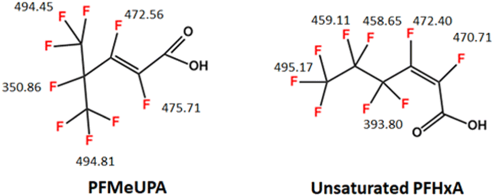 | ||
| Fig. 1 Chemical structure of PFMeUPA -unsaturated PFHxA – and a PFAS with a closely related structure. Numbers show BDE for the C–F bonds in kJ mol−1 that were determined in this study and are comparable with those reported in literature for PFMeUPA.43,45 Averaged values are presented for terminal CF3 groupings that can rotate. To date, studies reporting the successful reductive defluorination of PFAS using chemical reductants such as titanium citrate or nanoscale zerovalent zinc have required the addition of electron transfer mediators, such as vitamin B12, or a similar cobalt-centered porphyrins, to catalyze reduction.36,37,43,45,46 As vitamin B12 is known to readily sorb to GAC,47 it could act as a surface-specific catalyst in a GAC electrode system, and therefore the requirement of vitamin B12 for the reduction of PFMeUPA will be assessed in this study. | ||
An advantage of using an electrically driven system to reduce PFAS is the possibility of applying lower reduction potentials than those achievable using chemical reductants. This is significant as theoretical studies have predicted that even strong chemical reductants, such as zerovalent zinc, have half-lives on the order of years for the most recalcitrant PFAS and reduction potentials required are significantly lower than that achievable using zinc or titanium.48,49 The ability of our GAC system to achieve an increased rate of PFAS reduction with decreasing reduction potentials that are low enough to degrade two model PFAS will be explored in this study.
2. Materials and methods
2.1. Chemicals
(E)-Perfluoro(4-methylpent-2-enoic acid) (PFMeUPA, 97%) was purchased from SynQuest Laboratories (Alachua, FL). Perfluorooctane sulfonic acid potassium salt (PFOS) (98%) was purchased from Matrix Scientific. Zinc nanopowder (nZVZ, 40–60 nm, 40–50 m2 g−1, ≥99.0%), vitamin B12 (99.0%), high purity ammonium acetate (99.999%), high purity glacial acetic acid (99.7%), anhydrous sodium perchlorate, sodium sulfate (≥99.0%), sodium chloride (99%), sodium nitrate (≥99.0%), sodium hydroxyde (≥98%), potassium monobasic phosphate (≥99.0%), potassium dibasic phosphate (≥98.0%), potassium tribasic phosphate (≥98.0%), ferric chloride hexahydrate, sodium borohydride (≥98.0%) and sodium dithionite (≥82.0%) were supplied by Sigma-Aldrich (St. Louis, MO). HPLC-grade acetonitrile, methanol was purchased from Mallinckrodt Chemicals (Phillipsburg, NJ). Reagglomerated bituminous coal-based GAC (Filtrasorb400) was obtained from Calgon Carbon Corporation. All chemicals were utilized as received, except the GAC was rinsed multiple times with MilliQ water to remove ultrafine materials prior to use.All aqueous samples were prepared using ultrapure water (MilliQ water, Millipore Corporation, Burlington, MA).
2.2. Identification and quantification of PFMeUPA, PFOS and products
The loss of PFMeUPA and PFOS during reduction was analyzed by Ultra-High-Performance-Liquid Chromatography (UHPLC) using a Shimadzu Nexera X2 Liquid Chromatograph equipped with an XR-ODS-III (1.6 μm) 2 mm × 50 mm column maintained at 40 °C. For analysis, experimental samples were diluted 1000-fold into ultrapure water prior to analysis. From this, a 1 μL aliquot was loaded onto the column and eluted with 5 mM ammonia acetate in 0.05% w/w acetic acid (A) and 100% methanol (B) at a total flow rate of 200 μL min−1 for PFMeUPA or 0.4 mL min−1 for PFOS. The LC linear-gradient separation was set at: 50% B for the first 0.5 minutes, then increased to 100% B over 5 minutes before holding for 3 minutes and returning to 50% B over 0.5 min. The ramp was stabilized at 50% B for 1.5 min prior to the start of the next sample injection. Mass transitions were in negative electrospray ionization (ESI) mode. The precursor/product ion transitions monitored for PFMeUPA were 274.95/231 and 274.95/181. For each transition, the pause and dwell times were 3 and 5 ms, and the collision energies were 10 and 25 eV, respectively. For PFOS the precursor/product ion transitions monitored, paused and dwell times and collision energy details for each PFOS isomers are detailed in Table S1.† The LabSolutions Insight program was employed for data analysis with valley-to-valley manual peak area integration conducted. The limit of quantification (LOQ) was determined to be approximately 0.5 nM, which represents 10-fold the noise in an ultrapure water blank. Calibration standards were prepared to 5, 10, 25, 50, 75 and 100 μM of PFMeUPA or 10, 25, 50, 75 and 100 μM of PFOS.A Q-Exactive HF Mass Spectrometer (a hybrid instrument incorporating quadrupole and Orbitrap mass analyzers) with U3000 UHPLC system (ThermoFisher Scientific) was employed to analyze likely defluorinated products (refer to Table S2†). Masses for the most common isotopes were determined using the molecular weight calculator from PNNL.50 Samples were analyzed in negative ESI mode, with samples and blanks (consisting of the 0.1 M Na2SO4 background electrolyte) analyzed in random order. A C18 UHPLC column (Waters CSH C18 100 mm × 2.11), with matching guard column, was employed for separation. From undiluted samples, a 10 μL aliquot was injected onto the column. Separation was performed using 0.1% formic acid (A) and 0.1% formic acid in acetonitrile (B) at a total flow rate of 200 μL per minute. The gradient was held at 10% B for 2 minutes, ramped to 100% B at 10 minutes and held for 24 minutes before returning to 10% B at 25 minutes and holding for re-equilibration for an additional 5 minutes. The mass spectrometer was operated in data-dependent analysis mode – automatically acquiring MS/MS data. The instrument was scanned from 75–1000 at a resolution of 60 K, with MS/MS of the top 20 ions at 15 K. Source conditions were spray voltage 3.5 kV (negative), sheath gas 20 units, and auxiliary gas 5 units. The heater temperature was 50 °C, and the capillary temperature was 275 °C. The S-Lens was 50 V. The instrument was calibrated immediately prior to data acquisition, and lock masses used to maintain optimal mass accuracy. Data analysis was performed using XCalibur (ThermoFisher) with the mass tolerance set to 4 milli-mass units (mmu) for each likely product investigated (refer to Table S2†). Compounds were detected and peak areas obtained from accurate mass extracted ion chromatograms. Tandem mass spectrometry (MS/MS) data was used where possible to confirm compound identity by comparison to literature data but was not used for peak area determinations.
2.3. Theoretical calculations of C–F bond
The BDEs of C–F bonds in all proposed PFAS structures and degradation products were calculated with the Gaussian09D01 software package51 installed on the Katana52 high-performance computing cluster at the University of New South Wales. All molecular geometries were fully optimized using hybrid density functional theory (DFT) at the B3LYP/6-311+G(2d, 2p) level of theory53 corrected by Grimme's GD3-BJ empirical dispersion.54 Truhlar's SMD solvation model was selected to stimulate the aqueous environment implicitly.55The BDE for each C–F bond was calculated using eqn (1) (below), where H* represents the enthalpy of formation.
 | (1) |
2.4. Fluoride quantification
The concentration of fluoride was determined using a high-performance liquid chromatograph (Shimadzu Prominence Series) equipped with a conductivity detector and ion suppressor. From undiluted samples, a 5 μL sample was loaded onto an IC-SA3 anion exchange column (4 mm ID, 250 mm long) equipped with a 228-41600-92 guard column. The mobile phase was 3.6 mM sodium carbonate. The flow rate was fixed at 0.8 ml min−1, and the oven temperature was set to 50 °C. Due to the presence of substantial amounts of background electrolyte, analyses were performed for up to 90 min to ensure there was no electrolyte peak carryover from sample to sample. Quantification was based on peak area only by manual valley-to-valley peak integration using the LabSolutions Browser program with the concentration of samples determined against the peak area of standards prepared to 50, 100, 250, 500 and 1000 μM of fluoride.The extent of defluorination in each experiment was determined using eqn (2), where i represents the initial concentration of PFAS, such that the amount of fluoride released was calculated relative to the maximum possible amount of fluoride able to form. nF is the number of fluorides the PFAS molecule has, 9 for PFMeUPA and 17 for PFOS. Note that the initial concentration of fluoride (i.e. [F]i) was very small or negligible and could be omitted from eqn (2) without altering the calculated percentage of defluorination to 4 significant figures.
 | (2) |
2.5. Electrochemical reduction experiment preparation
For the H-cell setup, approximately 14.5 g of GAC was packed into a 2.5 cm diameter × 6.5 cm high stainless steel mesh holder to which titanium wire (1 mm) was attached. These cells functioned as both cathode and anode in the H-cell. A 450-micron thick CMI-7000 cation exchange membrane (with a DVB base and sulfonic acid functional groups) separated each cell (Fig. S1†). This membrane was conditioned in a 5% NaCl solution for 12 hours prior to use, followed by storage in ultrapure water. A 0.1 M sodium perchlorate or sodium sulfate electrolyte was employed in both cells, each of which was filled with 220 mL of electrolyte. In certain experiments 0.1 or 1 mM of sodium nitrate, a hydrated electron scavenger,25 was also present. PFMeUPA was introduced into the catholyte and allowed to mix well for a few seconds prior to collecting a 1 mL aliquot for the time 0 fluoride and PFMeUPA determination. The electrodes were then inserted into each cell, and the PFMeUPA was allowed to sorb to the cathode for at least 12 hours prior to the start of each experiment. Under these test conditions, complete sorption of PFMeUPA occurred within hours as the experiment was performed at a capacity of approximately 1.5 μmol of PFMeUPA per gram of GAC, which is well below the sorption capacity of approximately 20 μmol g−1 (Fig. S2†). The catholyte was then heated to 55, 70 or 85 °C using a heated stirrer equipped with a built-in thermocouple (Vevor HJ-6a) for electrochemical reduction and purged of oxygen by bubbling with nitrogen gas for at least 30 minutes prior to the application of the direct current (DC). Purging was achieved through a needle (Sterican, 21-gauge, 120 mm) pushed through a rubber septum at the top of the cell. After purging for 30 minutes, the nitrogen flow rate was turned down low, so it was no longer bubbling into the solution vigorously, and then the needle was lifted above the level of the liquid. Sampling was conducted using a separate 120 mm needle, with the 1 ml sample collected micro-centrifuged for 1 minute at 13000 rpm to remove any fine particulates prior to collecting aliquots for fluoride and parent/product determination. Reduction was achieved by the application of a fixed current from a 0 to 30 VDC, 0 to 5 A Regulated Power supply (PowerTech Plus). The reduction potential was measured using an HI13131B Ag/AgCl oxidation/reduction potential (ORP) probe containing 3 M NaCl connected to an HI5521 meter (Hanna Instruments Inc., USA). The platinum-sensing tip of the ORP probe touched the cathode during measurements. For pH buffered experiments, a 50 mM phosphate buffer was employed except where otherwise stated. At the end of each experiment, any sorbed species were removed by placing the GAC cathode in the same starting volume of methanol (i.e. 220 mL). This solution was capped and stirred for 24 hours, and then an aliquot removed for analysis of any remaining PFMeUPA in the same manner as described for the experimental samples.
To calculate the activation energy, the Arrhenius equation (eqn (3)) was used, where k is the rate constant (in s−1 for these first-order reactions), R is the universal gas constant = 8.314 J K−1 mol−1, T is temperature in Kelvin (K), A is the pre-exponential factor, and Ea is activation energy in J mol−1.
 | (3) |
2.6. Chemical reduction experiment preparation
For these experiments, sulfidized nano zerovalent iron (S-nZVI) was prepared by dissolving 12.05 g of Fe(III)Cl3·6H2O (i.e. 178 mM or 10 g L−1 of Fe) into 250 mL of water. Then a 250 mL solution containing 8.5 g of sodium borohydride and 0.975 g of sodium dithionite was added, dropwise, at an approximate rate of 7 mL min−1. The S-nZVI particles were then rinsed with ultrapure water three times and then twice with methanol, using a strong magnet to aid in the separation from the liquid phase. The final suspension was then prepared to a known volume between 50–100 mL. This procedure results in particles with an S:Fe molar ratio of 0.25. This represents a moderately high S:Fe ratio compared to other studies, and is expected to encourage high reductive reactivity.56 Sulfidized ZVI was employed as it is known to dramatically improve the longevity of ZVI's reductive reactivity,56 which is extremely important for reactions predicted to be extremely slow.49 Chemical reduction experiments were conducted in 50 mL crimp sealed glass flasks containing 150 mM S-nZVI or nZVZ (nanoscale zero valent zinc), 15 mM EDTA and 100 μM PFMeUPA in 0.1 M sodium sulfate electrolyte. EDTA was added at an EDTA:metal ratio of approximately 0.1, which has been shown to be optimal for the prevention of any passivating oxide layer.57 Suspensions were sampled anaerobically by the insertion of a syringe connected to a nitrogen gas line, whilst samples were extracted with another syringe. Samples were acquired every hour for 8 hours, and then at 24 and 48 hours for the nZVZ experiments, whilst the S-nZVI experimental samples were acquired at 1, 2, 7, 10, 14, 21 and 30 days.
2.7. Analysis of rates of reaction
Reported rate constants are all first-order and were determined by plotting the natural logarithm of concentration relative to time in seconds. Due to the 2 hour lag period at the start of the reaction, only the mid-range data points were employed for rate constant analyses. For example, for the electrochemical reactions, all data points between 2 and 5 hours (inclusive) were used for rate constant determination.3. Results and discussion
The electrochemical reductive defluorination of PFMeUPA using GAC electrodes was investigated in this study as a proof of concept to understand the degradation mechanisms and optimum conditions required for PFAS defluorination. The impact of initial pH, presence of organics, electrolyte used, temperature and reduction potential were examined for PFMeUPA degradation and degradation products were identified. Based on these findings, PFOS defluorination, a more recalcitrant PFAS, was investigated with VB12 as the catalyst.3.1. Impact of initial pH on defluorination
Batch experiments were initially conducted to optimize conditions necessary for reductive defluorination of PFMeUPA. The pH of the 0.1 M NaClO4 electrolyte was adjusted to 6.8 or 9.0 using 50 mM phosphate salt, or to 2.5 by using phosphoric acid. Changing the pH did not impact the solubility of PFMeUPA as its measured starting concentration (prior to the addition of the electrode) was 103.3 ± 2.8, 98.0 ± 0.0 and 102.7 ± 1.2 μM at pH 2.5, 6.8 and 9.0, respectively. These concentrations are within 2.67 ± 0.65%, on average, of the theoretical starting value of 100 μM. A 2 h lag preceded the defluorination of PFMeUPA after voltage application (Fig. 2b). Over this lag period the pH increased to 11.5 when the initial pH was either 6.8 or 9.0, or to pH 6.0 when the initial pH was 2.5 (Fig. 2a). The pH increase during this period was due to water reduction.58 After the 2 hour lag period, the rate of reductive defluorination started to increase (Fig. 2b) with measured first-order defluorination rates of 1.54 ± 0.21, 6.63 ± 0.1 and 3.94 ± 0.67 × 10⁻⁵ M s−1 for the time points from 2 to 5 h for experiments where the initial pH was 2.5, 6.8 and 9.0, respectively. The initial induction period and low rate of reduction when the initial pH was 2.5 and then remained circumneutral after 2.5 h (Fig. 2a) suggests reduction may be occurring through hydrated electrons (eaq−) since they are more rapidly neutralized by protons at acidic pH values.59 However, the rate of reduction at an initial pH of 9.0 or 2.5 was slower than that at an initial pH of 6.8 (Fig. 2b), even though alkaline conditions are favorable for reduction reactions.23 This indicates that pH 6.8 may represent the balance between the optimum pH for both sides of the H-cell (which is approximately 11.5 for the catholyte, and 2.5 for the anolyte). Experiments conducted in a single-cell setup provide more conclusive evidence that maintaining an alkaline pH in the cell favors a higher rate of PFMeUPA reduction (Fig. 3). As mentioned previously, a higher rate of PFMeUPA reduction at alkaline pH may be suggestive of the involvement of eaq−, and hence this was investigated using nitrate; a common freshwater constituent and a known eaq− scavenger.23 | ||
| Fig. 2 Catholyte pH profile (a) and mole equivalent fluoride production (b) following the application of an applied cell voltage of 10 V (equiv. to approx. 10 mA cm−2) in 0.1 M NaClO4 unbuffered solutions heated to 70 °C. Starting [PFMeUPA] = 100 μM. Data points are averages of duplicate measurements, with error bars representing the range about the average. | ||
 | ||
| Fig. 3 Natural logarithm of PFMeUPA concentration following the application of 10 V to the cell in a 0.1 M Na2SO4 unbuffered solution heated to 70 °C. Stated pH ranges are starting and final pH values. Initial [PFMeUPA] was 100 μM. Experiments conducted using a single-cell configuration. Data points are the average of duplicate measurements, and error bars represent the range about the average. Lines of best fit to the data are included and used to determine the rate constant for these reactions. | ||
3.2. Impact of nitrate on defluorination
In the presence of equal or higher concentrations of nitrate, there was a decrease in system performance (Fig. 4). However, despite having a nitrate concentration up to 625-fold higher than a typical nitrate contaminated water standard of 0.16 mM (or 10 mg L−1), PFMeUPA reduction only decreased by 12.7 ± 0.55% (Fig. 4). This small decrease in performance highlights the robustness of this system towards PFAS reduction. The minor impact of this powerful eaq− scavenger can be explained by the presence of PFAS at the surface of the electrode. Hydrated electrons are produced at the electrode surface and typically react within a short distance, ∼10−9 m. Hence, having the pollutant on the same surface minimizes any competing reactions with reducible contaminants in the aqueous phase. Direct evidence, however, is required to confirm any involvement of hydrated electrons in these reactions, requiring specialized high temporal resolution spectroscopic measurements60 or spin-trap experiments24 beyond the scope of our experimental capabilities. | ||
| Fig. 4 Impact of 100 μM or 1 mM nitrate on (a) the reduction in aqueous PFMeUPA concentration or (b) the formation of fluoride following the application of 10 V to an H-cell containing 100 μM PFMeUPA and unbuffered 0.1 M NaSO4 heated to 70 °C. Data points represent the average of duplicate measurements and error bars represent the range. Note that the time zero PFMeUPA measurement represented here is that measured after 12 h of adsorption as the data points represent the measured aqueous PFMeUPA concentration. | ||
3.3. Impact of electrolyte on defluorination
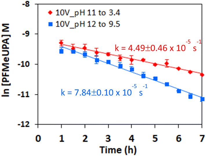
Considering the use of a buffered electrolyte was unable to prevent changes in pH, with the H-cell anolyte and catholyte after 2 hours becoming acidic (pH ∼2.5) and basic (pH ∼11.5), respectively, the use of unbuffered solutions within the H-cell were investigated. The use of two common electrolytes in electrochemical studies were investigated for improved performance. The use of unbuffered 0.1 M Na2SO4 resulted in higher rates of defluorination compared to 0.1 M NaClO4 (Fig. S4†), with rate constants of 9.15 ± 1.32 × 10⁻⁵ s−1 in 0.1 M Na2SO4 and 7.54 ± 0.33 × 10⁻⁵ s−1 in 0.1 M NaClO4. As such, all experiments were performed in unbuffered 0.1 M Na2SO4 from hereon. This is also advantageous as sodium sulfate has a lower environmental toxicity profile compared to sodium perchlorate.61 Note that lower electrolyte concentrations were trialed but did not provide sufficient conductivity as evidenced by the much lower amperage achieved and tendency for the cell to burn out.As previous studies have demonstrated that vitamin B12 is an effective catalyst for enhancing the reductive reactivity of PFAS,36,45 the impact of adding this catalyst to our system was investigated. Interestingly, the addition of vitamin B12 did not provide any additional reductive reactivity towards PFMeUPA in these studies (Fig. S5†), with the rate of defluorination of 7.9 ± 1.29 × 10⁻⁵ s−1 being similar, within error. This is most likely associated with the ease with which PFMeUPA undergoes reduction in this system, with the use of a catalyst still expected to be important for more recalcitrant PFAS.
3.4. Impact of temperature on defluorination
The impact of temperature was investigated in unbuffered 0.1 M Na2SO4 by setting the temperature of the catholyte to 55, 70 or 85 °C. Controls indicated that no PFAS destruction or fluoride generation occurred in experiments in which there was no applied voltage, indicating losses are not attributable to the high temperatures employed (Fig. S6†). Whilst the temperatures employed may seem extreme for a system intended to be field-based, it is important to consider that breakage of the C–F bond in PFAS represents the most difficult carbon-based bond to break. Indeed, temperatures up to 650 °C have been employed for recent field-based destruction systems.62The degree of PFMeUPA degradation and defluorination achieved in these experiments is shown in Fig. S7 and S8† and indicates that an increase in temperature increased the rate of reaction. As desorption of PFMeUPA occurred after 2 hours of applied voltage (Fig. S7†), its concentration in solution could be measured to determine a rate of PFMeUPA loss. The mass balance between fluoride and dissolved PFMeUPA at each timepoint is shown in Fig. S8.† Considering that desorption of PFMeUPA from the cathode at the end of each experiment did not recover any measurable PFMeUPA, Fig. S8† indicates that in the 55 and 70 °C experiments, PFMeUPA completely transformed into either fluoride or other poly-fluorinated products by 8 hours, whilst at 85 °C the mass balance indicates PFMeUPA underwent complete defluorination. These results show a 27.1% increased defluorination percentage in 86.7% less time compared to the only other study investigating PFMeUPA electrochemical reduction.27 Note that the 85 °C control experiments achieved at least 95% recovery of added PFMeUPA after desorption (Fig. S6†) indicating these experiments were not impacted by sorptive or volatile losses.
First-order rate constants of 1.30 ± 0.03 × 10⁻⁴ s−1, 1.71 ± 0.04 × 10⁻⁴ s−1 and 2.67 ± 0.11 × 10⁻⁴ s−1 at 55, 70 and 85 °C respectively (Fig. 5a) were determined from these experiments. Using the Arrhenius equation (eqn (3); Fig. 5b), an activation energy of 23.32 ± 2.81 kJ mol−1 was determined for this reaction. Whilst there are no other studies that report an activation energy for PFMeUPA reductive defluorination with which to compare, there are numerous studies that report activation energies for other PFAS. For example, an activation energy of approximately 240 kJ mol−1 is reported for the thermal decomposition of PFOS,63 whilst the reduction of PFOS by photo-generated hydrated electrons reduces this to approximately 25 kJ mol−1.64 Similarly, the thermal decomposition of PFOA has a reported activation energy of approximately 113 kJ mol−1,65 whilst persulfate oxidation of PFOA has an activation energy of approximately 60 kJ mol−1.66 As such, the activation energy determined in this study is similar to that achieved by cleavage of the initial C–F bond in PFOS by photo-generated hydrated electrons.
 | ||
| Fig. 5 (a) Natural logarithm of PFMeUPA concentration as a function of time following the application of an applied cell voltage of 10 V in 0.1 M Na2SO4 solutions at different starting temperatures and (b) Arrhenius plot of inverse temperature (in Kelvin) vs. rate constant (in seconds) for these reactions on the right. Data points are the average of duplicate measurements, and error bars represent the range about the average. | ||
The electrical energy per order (EEO), measured in kW h m−3, was calculated for the removal of PFMeUPA over 8 hours based on the temperature dependent concentration data presented in Fig. S7,† and the energy used for heating up the electrolyte to the desired temperature using eqn (4) below;
 | (4) |
Overall, these results indicate that GAC can be used as both a sorptive and electro-active material to trap and reductively degrade PFAS and, is therefore, a possible alternative treatment to more energy-intensive thermal treatment processes that can liberate toxic by-products such as dioxins.69 The results may also be applied to soil where GAC has been added to immobilize or stabilize PFAS to treat PFAS in situ, in a similar manner to that demonstrated in previous studies.70 This would dispense the need to remove copious amounts of soil to mineralize sorbed PFAS.69 It is appreciated, however, that soils are complex systems with potential competing dissolved species, and therefore the efficacy and feasibility of such an electrochemical system to mineralize PFAS under field conditions would need to be investigated.
3.5. Impact of reduction potential on defluorination
The effect of reduction potential on the first-order rate of reduction was compared to chemical reduction with different electron donors, and indicates that a more negative reduction potential results in faster PFMeUPA reduction (Fig. 6a). Note that all experiments were conducted in 0.1 M Na2SO4 and held at 70 °C for consistency. Sulfidized nano zerovalent iron (S-nZVI) and nano zerovalent zinc (nZVZ) were employed as electron donors, with the reduction potential of these metals reported to be −0.44 and −0.76 V vs. SHE under standard conditions.49 As a result of their differing reduction potential, the reducing ability of the two metals differed greatly, with S-nZVI displaying very slow PFMeUPA reduction at 70 °C, with a calculated half of life 78 days from the first order rate constant obtained (= 1.03 × 10⁻⁷ s−1). This compares to a calculated half-life of 1.7 h for nZVZ at 70 °C. Note that the specific surface area of both the nZVZ and S-nZVI particles are reported to be approximately 40–50 m2 g−1,56 and, as such, they were present at comparable concentrations and reactive surface areas. For the GAC electrode it was difficult to determine the reactive surface area. At 1012 m2 g−1, the surface area of GAC is ∼20× larger,71 and the experiments were performed at well above the sorption capacity for PFMeUPA as stated in the methodology. As such, the electron source was by no means limiting in the electrochemical system investigated, and therefore significant differences in reductive reactivity are more likely to relate to differences in reduction potential. The catholyte stabilized within 2 hours to approximately −1230 mV vs. Ag/Ag+ following the application of an applied voltage of 10 V. Upon altering the voltage in the H-cell setup between 7.5 and 12.5 V, there was no difference in the measured reduction potential at the cathode, and at an applied voltage of 15 V, the anode was not stable with respect to oxidation over the reaction period. This is most likely related to the material used to house the GAC, which was stainless steel and therefore unable to withstand high oxidative potentials. A more robust housing material is required for the use of this electrode system for multiple reduction cycles as the housing displayed evidence of oxidation over the timeframe of these experiments. Nevertheless, even in its current form, the electrode system employed in this study indicates the feasibility and energy savings associated with the electrolytic treatment of PFAS-contaminated GAC relative to thermal destruction.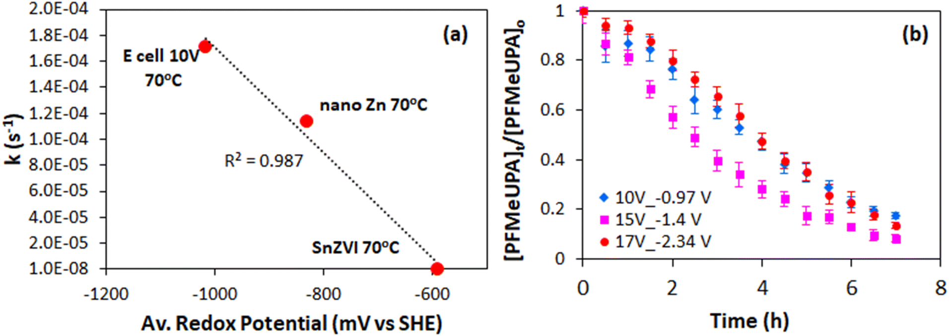 | ||
| Fig. 6 (a) Effect of theoretical reduction potential on the measured first-order rate of PFMeUPA attenuation in 0.1 M sodium sulfate at 70 °C using SnZVI, nZVZ and applied voltage as electron sources. (b) Effect of increasing applied voltage (in V) and decreasing measured reduction potential at the cathode (in V vs. SHE) towards the reduction of PFMeUPA in the single electrochemical cell setup at 70 °C. Error bars represent one standard deviation from the mean (n = 3). | ||
In the single-cell setup, where a titanium sheet was employed as the anode and GAC in stainless steel mesh was employed for the cathode, we were able to apply higher voltages and achieve changes in the measured reduction potential at the cathode. Above a measured reduction potential of −1.4 V vs. SHE, however, the rate of PFMeUPA reduction decreased (Fig. 6b), indicating that reduction is limited at higher negative potentials. Exactly why this is the case requires further investigation as −1.5 V vs. SHE is theoretically required to achieve reductive defluorination of the most recalcitrant PFAS, PFOS and PFOA.48 Generation of oxygen at the anode may have impacted the performance of the cathode in the single-cell, so optimizing a separate cell design through the use of a GAC housing material that is able to better withstand oxidation and minimizing the distance between the electrodes, should be investigated in future studies. Further experiments using an active anode able to oxidatively breakdown PFAS would also be useful to investigate in future single-cell setups.
3.6. Elucidation of degradation products
The amount of fluoride released at the various temperatures investigated indicates complete defluorination of added PFMeUPA (100 μM) occurred in the reactions at 85 °C as nine molar equivalents of fluoride were released (Fig. S7†). We were therefore interested in determining what degradation products formed in this reaction. This was assessed by determining the relative abundance of each product in comparison to the parent compound, as analytical standards for each product are not available for accurate quantification. Level 2 confidence in these degradation product structures is afforded considering the known parent compound information, experimental context and high mass resolution employed in this study, where the match between the expected product mass and that observed was less than 1 mmu (Table S2†).72 The results (Fig. 7) indicate successive loss of fluoride atoms and replacement with hydrogen atoms (i.e. hydrodefluorination). As more fluoride was removed, however, determination of the degradation products with certainty became difficult, and we were unable to see any evidence of a fully defluorinated product in these experiments. This may be due to the sorption of degradation products to GAC, as well as the volatilization of lighter products in the H-cell (due to N2 purging), despite efforts to recover any sorbed species at the end of the experiment using desorption into methanol. | ||
| Fig. 7 % peak area intensity at each reaction time over the maximum peak area intensity at all reaction time points for observed hydrodefluorination products during the reduction of PFMeUPA in 0.1 M Na2SO4 following the application of 10 V in the H-cell at 85 °C. Each degradation product is identified by the number of fluorides lost from the parent compound, PFMeUPA. Note that areas for the background electrolyte were either 0 or negligible for most product species (Table S3†). | ||
As such, the samples generated from the reduction of zinc at 70 °C (in which sorption and volatilization of any products are expected to be minimal) were also analyzed for degradation products. Similar to the results noted for the electrochemical reduction experiments, the reduction of PFMeUPA through stepwise hydrodefluorination was observed (Fig. 8). In these experiments, however, we were able to observe the formation of a fully defluorinated product equivalent to the loss of 9 fluoride atoms from the parent via hydrodefluorination with an M–H− mass of 113.0609. Full details of the mass of each product determined, the integrated peak areas and the associated retention times for each identified degradation product are provided in Tables S1 and S2,† with screenshots of the peaks identified provided in Fig. S9.† Overall, the electrochemical H-cell and zinc reduction experiments yielded the same products, with the exception of the fully defluorinated product which was only identified in the latter. This is most likely associated with less sorption/volatile losses of degradation products in the zinc samples, as indicated by the much more prominent peak areas of the products from these samples (Table S3†).
 | ||
| Fig. 8 % peak area intensity at each reaction time over the maximum peak area intensity at all reaction time points for observed hydrodefluorination products during the reduction of 100 μM PFMeUPA in the presence of 150 mM of nano-zinc at 70 °C in 0.1 M Na2SO4. Each degradation product is identified by the number of fluorides lost from the parent compound, PFMeUPA. Note that areas for the background electrolyte were either 0 or negligible for most product species (Table S3†). | ||
Full details of the BDE calculations for each product identified are provided in Fig. S10.† According to these calculations, the first fluoride expected to be lost is the tertiary carbon fluoride, consistent with the results of other studies.43 The two fluoride atoms about the double bond are then the next two lowest energy C–F bonds. Then stepwise hydrodefluorination occurs until six fluoride atoms are lost from the parent compound. At this point, the remaining carbon atom with three fluorides attached is expected to lose these atoms rapidly once the initial fluoride bond is broken, hence why we don't see evidence of hydrodefluorination products with 7 or 8 less fluorides than the parent. To summarize these findings, a flow chart of the various products that are indicated to form according to the MS/MS data and BDE is shown in Fig. 9.
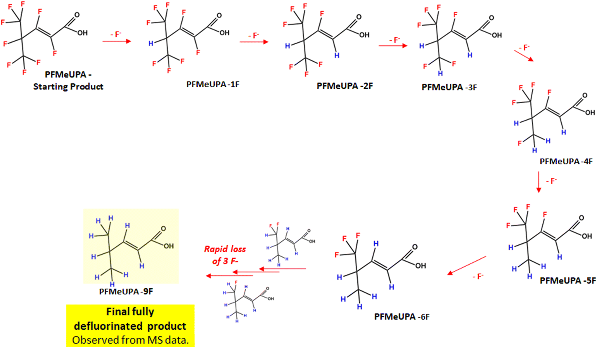 | ||
| Fig. 9 Flowchart of PFMeUPA reductive defluorination products identified to form using LC-HRMS data and BDE calculations. | ||
That defluorination is able to occur in our system is suggestive of an advanced reductive process, such as those involving hydrated electrons, which are powerful C–F bond cleavers44 and can be generated from the electrolysis of water.59 Further evidence of a reaction with hydrated electrons is the faster rate of hydro-defluorination in the presence of a basic catholyte and reduced defluorination in the presence of nitrate, although direct evidence is required to confirm the involvement of hydrated electrons in these reactions.
3.7. PFOS degradation experiments
The degradation of PFOS was investigated using the optimized system by setting the catholyte temperature at 85 °C and 15 V. The effects of using vitamin B12 as a catalyst for PFOS degradation were examined. Controls indicated that no PFAS destruction or fluoride generation occurred in experiments in which there was no applied voltage or where PFOS was not added, and 15 V were applied. As shown in Fig. 10A, 3.6 ± 0.3% of PFOS defluorination was attained in the absence of the catalyst after 4 hours, increasing to 7.9 ± 0.6% with a catalyst. The increased defluorination can be attributed to the change in oxidation state of the cobalt (Co) present in the VB12 structure from three to one (CoIII to CoI).73 CoI is a known nucleophile that is capable of breaking the C–F bond.73,74 The results using a catalyst show comparable defluorination percentage to other advanced reduction studies75 but lower than that obtained for PFMeUPA using this system after four hours. Nonetheless, the results highlight the potential of this system to treat more recalcitrant PFAS.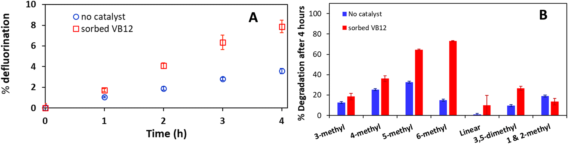 | ||
| Fig. 10 (A) PFOS defluorination percent based on fluoride analysis as a function of time following the application of 15 V at 85 °C in 0.1 M Na2SO4 solutions with (red) or without (blue) the addition of vitamin B12 as a catalyst. (B) Branched PFOS isomers degradation without a catalyst (blue) and with the addition of vitamin B12 as the catalyst (red) measured with LCMS. Data points are averages of duplicate measurements, with error bars representing the range about the average. | ||
Analysis of the specific isomer degradation was conducted to further understand the mechanisms involved using this system. Branched PFOS represent up to 30% of technical PFOS and it is subjected to PFOS regulations.5,76 As such, developing a system that can degrade branched PFOS is desirable. As shown in Fig. S11,† 5- and 6-methyl PFOS are targeted by this system while linear PFOS did not break down. Depending on the presence of the catalyst, the ratios of which isomers were targeted also varied (Fig. 10B). As demonstrated in previous studies, the location of the branch in relation to the functional head group affects the electron density distribution and backbone angles.46,77 This translates into linear PFOS being much harder to degrade compared to 5- and 6-methyl PFOS. Testing the use of different catalysts should be done in future studies.
Under the current set up, the titanium anode wire could not withstand the extreme conditions, and the experiment could not be performed for longer. Excessive amount of GAC fine powder was produced and coated the membrane from 2 h onwards. Hence, only preliminary experiments were conducted with PFOS to provide an insight into using this system to degrade recalcitrant PFAS and to which modifications would need to be made to the cell design.
4. Conclusions
The results indicate that a decrease in reduction potential and increase in temperature can be used to amplify the thermodynamic driving potential for more recalcitrant PFAS such as PFOS using the simple GAC electrochemical reduction system investigated in this study. However, whilst the rate of reduction was found to increase linearly with decreasing reduction potential using a range of different electron sources, the H-cell system in this study was unable to be tuned to a reduction potential different to that generated at 10 V (which was approximately −1 V vs. SHE). In the single-cell system investigated, the reduction potential measured approximately −1 V vs. SHE when 10 V was applied, and −1.4 V vs. SHE when 15 V was applied, with no further increase in the rate of PFMeUPA reduction observed when the reduction potential was decreased to −2.34 V following the application of 17 V. Further experiments using an anode able to oxidize target PFAS molecules and the use of electrical contacts made of metals able to withstand higher oxidative potentials (such as titanium or platinum) should be investigated in follow-on studies.Sodium sulfate displayed better performance than sodium perchlorate as an electrolyte, and the use of vitamin B12 did not enhance the reduction reactivity towards PFMeUPA under the conditions tested. Finally, the results show that the target PFAS degrades through sequential hydrodefluorination, and that the activation energy for this reaction was calculated to be 23.3 kJ mol−1, which is similar to that achieved by cleavage of the initial C–F bond in PFOS by photo-generated hydrated electrons.
PFOS defluorination was achieved following the application of 15 V at 85 °C, but not to the desired extent (i.e., <10%). Unlike PFMeUPA, the addition of vitamin B12 as a catalyst was crucial for defluorination. 5- and 6-methyl PFOS were the targeted isomers in this system consistent with the PFOS reductive defluorination pathways. Further experiments testing other catalysts and anode materials that can withstand extreme conditions should be investigated with an aim to reduce linear PFAS (e.g., PFOS).
Overall, this study has demonstrated that the use of GAC as a reactive platform for the electrochemical destruction of PFAS is a viable alternative to thermal destruction. The efficiency of an optimized system towards the reduction of other PFAS, particularly those of current regulatory concern and considered to be particularly recalcitrant (e.g. PFOS, PFOA) should be investigated as a logical next step and the system investigated and scaled up for field applications at contaminated sites.
Author contributions
Diana Ackerman Grunfeld: formal analysis, investigation, methodology, validation, visualization, writing – original draft, review and editing. Adele M. Jones: conceptualization, formal analysis, investigation, methodology, supervision, validation, visualization, writing – original draft, review and editing. Jun Sun: formal analysis, investigation, methodology, software, writing – review and editing. Song Thao Le: investigation, methodology, writing – review and editing. Russell Pickford: investigation, methodology, validation, resources. Qingguo Huang: funding acquisition, writing – review and editing. Michael Manefield: funding acquisition, writing – review and editing. Naresh Kumar: funding acquisition, project administration, writing – review and editing. Matt Lee: conceptualization, funding acquisition, supervision, writing – review and editing. Denis M. O'Carroll: conceptualization, funding acquisition, resources, supervision, writing – review and editing.Conflicts of interest
There are no conflicts of interest to declare.Acknowledgements
The Australian Government Research Training Program Scholarship is acknowledged for the support of Diana Ackerman Grunfeld. The Australian Research Council (ARC) Special Research Initiatives (Project ID: SR180100030) is acknowledged for the provision of research funding. The Bioanalytical Mass Spectroscopy Facility at UNSW (University of New South Wales), Sydney is acknowledged for facilitating the analysis of breakdown products. This research includes computations that were undertaken using the computational cluster Katana supported by Research Technology Services at UNSW Sydney.References
- M. Haukås, U. Berger, H. Hop, B. Gulliksen and G. W. Gabrielsen, Bioaccumulation of per- and polyfluorinated alkyl substances (PFAS) in selected species from the Barents Sea food web, Environ. Pollut., 2007, 148(1), 360–371, DOI:10.1016/j.envpol.2006.09.021; F. Li, J. Duan, S. Tian, H. Ji, Y. Zhu, Z. Wei and D. Zhao, Short-chain per- and polyfluoroalkyl substances in aquatic systems: Occurrence, impacts and treatment, Chem. Eng. J., 2020, 380, 122506, DOI:10.1016/j.cej.2019.122506.
- N. J. M. Fitzgerald, A. Wargenau, C. Sorenson, J. Pedersen, N. Tufenkji, P. J. Novak and M. F. Simcik, Partitioning and accumulation of perfluoroalkyl substances in model lipid bilayers and bacteria, Environ. Sci. Technol., 2018, 52(18), 10433–10440, DOI:10.1021/acs.est.8b02912.
- F. Pérez, M. Nadal, A. Navarro-Ortega, F. Fàbrega, J. L. Domingo, D. Barceló and M. Farré, Accumulation of perfluoroalkyl substances in human tissues, Environ. Int., 2013, 59, 354–362, DOI:10.1016/j.envint.2013.06.004.
- J. E. Huheey, E. A. Keiter and R. L. Keiter, Inorganic Chemistry: Principles of structure and reactivity, Harper Collins College, 4th edn, 1993 Search PubMed.
- R. C. Buck, J. Franklin, U. Berger, J. M. Conder, I. T. Cousins, P. de Voogt, A. A. Jensen, K. Kannan, S. A. Mabury and S. P. van Leeuwen, Perfluoroalkyl and polyfluoroalkyl substances in the environment: Terminology, classification, and origins, Integr. Environ. Assess. Manage., 2011, 7(4), 513–541, DOI:10.1002/ieam.258.
- M. J. Perry, G. N. Nguyen and N. D. Porter, The current epidemiologic evidence on exposures to poly- and perfluoroalkyl substances (PFASs) and male reproductive health, Curr. Epidemiol. Rep., 2016, 3(1), 19–26, DOI:10.1007/s40471-016-0071-y.
- K. Steenland, L. Zhao, A. Winquist and C. Parks, Ulcerative colitis and perfluorooctanoic acid (PFOA) in a highly exposed population of community residents and workers in the mid-ohio valley, Environ. Health Perspect., 2013, 121(8), 900–905, DOI:10.1289/ehp.1206449 (accessed 2021/06/30).
- M. Song, Y.-J. Kim, Y.-K. Park and J.-C. Ryu, Changes in thyroid peroxidase activity in response to various chemicals, J. Environ. Monit., 2012, 14(8), 2121–2126, 10.1039/C2EM30106G.
- K. Steenland and A. Winquist, PFAS and cancer, a scoping review of the epidemiologic evidence, Environ. Res., 2021, 194, 110690, DOI:10.1016/j.envres.2020.110690; National Toxicology Program, NTP technical report on the toxicology and carcinogenesis studies of Perfluorooctanoic Acid (CASRN 335-67-1) administered in feed to Sprague Dawley rats, 598, Research Triangle Park (NC), 2020, https://doi.org/10.22427/NTP-TR-598 CrossRef PubMed; E. T. Chang, H.-O. Adami, P. Boffetta, P. Cole, T. B. Starr and J. S. Mandel, A critical review of perfluorooctanoate and perfluorooctanesulfonate exposure and cancer risk in humans, Crit. Rev. Toxicol., 2014, 44(sup1), 1–81, DOI:10.3109/10408444.2014.905767.
- ITRC, PFAS Technical and Regulatory Guidance Document and Fact Sheets PFAS-1, Interstate Technology & Regulatory Council, PFAS Team, Washington, D.C., 2020, https://pfas-1.itrcweb.org/ Search PubMed.
- A. J. Williams, L. G. T. Gaines, C. M. Grulke, C. N. Lowe, G. F. B. Sinclair, V. Samano, I. Thillainadarajah, B. Meyer, G. Patlewicz and A. M. Richard, Assembly and curation of lists of per- and polyfluoroalkyl substances (PFAS) to support environmental science research, Front. Environ. Sci., 2022, 10, 850019, DOI:10.3389/fenvs.2022.850019.
- A. L. Luz, J. K. Anderson, P. Goodrum and J. Durda, Perfluorohexanoic acid toxicity, part I: Development of a chronic human health toxicity value for use in risk assessment, Regul. Toxicol. Pharmacol., 2019, 103, 41–55, DOI:10.1016/j.yrtph.2019.01.019.
- S. E. Fenton, A. Ducatman, A. Boobis, J. C. DeWitt, C. Lau, C. Ng, J. S. Smith and S. M. Roberts, Per- and polyfluoroalkyl substance toxicity and human health review: Current state of knowledge and strategies for informing future research, Environ. Toxicol. Chem., 2021, 40(3), 606–630, DOI:10.1002/etc.4890 (accessed 2021/09/23).
- S. Brendel, É. Fetter, C. Staude, L. Vierke and A. Biegel-Engler, Short-chain perfluoroalkyl acids: environmental concerns and a regulatory strategy under REACH, Environ. Sci. Eur., 2018, 30(1), 9, DOI:10.1186/s12302-018-0134-4.
- Q. Wang, M. M. P. Tsui, Y. Ruan, H. Lin, Z. Zhao, J. P. H. Ku, H. Sun and P. K. S. Lam, Occurrence and distribution of per- and polyfluoroalkyl substances (PFASs) in the seawater and sediment of the South China sea coastal region, Chemosphere, 2019, 231, 468–477, DOI:10.1016/j.chemosphere.2019.05.162.
- S. A. Bălan, V. C. Mathrani, D. F. Guo and A. M. Algazi, Regulating PFAS as a chemical class under the California Safer Consumer Products program, Environ. Health Perspect., 2021, 129(2), 025001, DOI:10.1289/EHP7431; I. T. Cousins, J. C. DeWitt, J. Glüge, G. Goldenman, D. Herzke, R. Lohmann, C. A. Ng, M. Scheringer and Z. Wang, The high persistence of PFAS is sufficient for their management as a chemical class, Environ. Sci.: Processes Impacts, 2020, 22(12), 2307–2312, 10.1039/D0EM00355G; C. F. Kwiatkowski, D. Q. Andrews, L. S. Birnbaum, T. A. Bruton, J. C. DeWitt, D. R. U. Knappe, M. V. Maffini, M. F. Miller, K. E. Pelch and A. Reade, et al., Scientific basis for managing PFAS as a chemical class, Environ. Sci. Technol. Lett., 2020, 7(8), 532–543, DOI:10.1021/acs.estlett.0c00255.
- European Commission, Chemicals strategy for sustainability towards a toxic-free environment, Brussels, 2020, https://environment.ec.europa.eu/strategy/chemicals-strategy_en Search PubMed.
- Health Canada, Per- and polyfluoroalkyl substances (PFAS) in drinking water, 2023, https://www.canada.ca/en/health-canada/services/environmental-workplace-health/reports-publications/water-quality/water-talk-per-polyfluoroalkyl-substances-drinking-water.html (accessed 2023 June 1) Search PubMed.
- T. D. Appleman, C. P. Higgins, O. Quiñones, B. J. Vanderford, C. Kolstad, J. C. Zeigler-Holady and E. R. V. Dickenson, Treatment of poly- and perfluoroalkyl substances in U.S. full-scale water treatment systems, Water Res., 2014, 51, 246–255, DOI:10.1016/j.watres.2013.10.067 , PubMed.
- Calgon Carbon, Removal of short chain pfas compounds via GAC- RSSCT summary report, RSSCT Summary Report, 2017, https://www.chemviron.eu/fileadmin/speciality_distribution/public/documents/PFAS/Summary-Report-Removal-of-Short-Chain-PFAS-Compounds-via-GAC.pdf Search PubMed.
- R. DiStefano, T. Feliciano, R. A. Mimna, A. M. Redding and J. Matthis, Thermal destruction of PFAS during full-scale reactivation of PFAS-laden granular activated carbon, Remediation Journal, 2022, 32(4), 231–238, DOI:10.1002/rem.21735.
- V. A. A. Espana, M. Mallavarapu and R. Naidu, Treatment technologies for aqueous perfluorooctanesulfonate (PFOS) and perfluorooctanoate (PFOA): A critical review with an emphasis on field testing, Environ. Technol. Innovation, 2015, 4, 168–181, DOI:10.1016/j.eti.2015.06.001.
- J. Cui, P. Gao and Y. Deng, Destruction of per- and polyfluoroalkyl substances (PFAS) with advanced reduction processes (ARPs): A critical review, Environ. Sci. Technol., 2020, 54(7), 3752–3766, DOI:10.1021/acs.est.9b05565.
- H. Tian, J. Gao, H. Li, S. A. Boyd and C. Gu, Complete defluorination of perfluorinated compounds by hydrated electrons generated from 3-indole-acetic-acid in organomodified montmorillonite, Sci. Rep., 2016, 6(1), 32949, DOI:10.1038/srep32949.
- S. F. Patil, A. G. Bedekar and R. M. Patil, γ-Radiolysis of isobutanol and nitrate in aqueous solution, J. Radioanal. Nucl. Chem., 1992, 158(1), 107–114, DOI:10.1007/BF02034777.
- Q. Guo, Q. Yue, J. Zhao, L. Wang, H. Wang, X. Wei, J. Liu and J. Jia, How far can hydroxyl radicals travel? An electrochemical study based on a DNA mediated electron transfer process, Chem. Commun., 2011, 47(43), 11906–11908, 10.1039/C1CC14699H.
- Y. Wang, Y. Xiao, Y. Wang, Q. Lin, Y. Zhu, Z. Ni and R. Qiu, Electroreductive Defluorination of Unsaturated PFAS by a Quaternary Ammonium Surfactant-Modified Cathode via Direct Cathodic Reduction, Environ. Sci. Technol., 2023, 57(19), 7578–7589, DOI:10.1021/acs.est.2c08182.
- S. Sukeesan, N. Boontanon and S. K. Boontanon, Improved electrical driving current of electrochemical treatment of per- and polyfluoroalkyl substances (PFAS) in water using boron-doped diamond anode, Environ. Technol. Innovation, 2021, 23, 101655, DOI:10.1016/j.eti.2021.101655; M. Pierpaoli, M. Szopińska, B. K. Wilk, M. Sobaszek, A. Łuczkiewicz, R. Bogdanowicz and S. Fudala-Książek, Electrochemical oxidation of PFOA and PFOS in landfill leachates at low and highly boron-doped diamond electrodes, J. Hazard. Mater., 2021, 403, 123606, DOI:10.1016/j.jhazmat.2020.123606.
- B. Yang, C. Jiang, G. Yu, Q. Zhuo, S. Deng, J. Wu and H. Zhang, Highly efficient electrochemical degradation of perfluorooctanoic acid (PFOA) by F-doped Ti/SnO2 electrode, J. Hazard. Mater., 2015, 299, 417–424, DOI:10.1016/j.jhazmat.2015.06.033; H. Lin, J. Niu, J. Xu, H. Huang, D. Li, Z. Yue and C. Feng, Highly efficient and mild electrochemical mineralization of long-chain perfluorocarboxylic acids (C9-C10) by Ti/SnO2-Sb-Ce, Ti/SnO2-Sb/Ce-PbO2, and Ti/BDD electrodes, Environ. Sci. Technol., 2013, 47(22), 13039–13046, DOI:10.1021/es4034414 From NLM; H. Lin, J. Niu, S. Ding and L. Zhang, Electrochemical degradation of perfluorooctanoic acid (PFOA) by Ti/SnO2-Sb, Ti/SnO2-Sb/PbO2 and Ti/SnO2-Sb/MnO2 anodes, Water Res., 2012, 46(7), 2281–2289, DOI:10.1016/j.watres.2012.01.053 From NLM; Q. Zhuo, S. Deng, B. Yang, J. Huang and G. Yu, Efficient electrochemical oxidation of perfluorooctanoate using a Ti/SnO2-Sb-Bi anode, Environ. Sci. Technol., 2011, 45(7), 2973–2979, DOI:10.1021/es1024542.
- H. Lin, J. Niu, S. Liang, C. Wang, Y. Wang, F. Jin, Q. Luo and Q. Huang, Development of macroporous Magnéli phase Ti4O7 ceramic materials: As an efficient anode for mineralization of poly- and perfluoroalkyl substances, Chem. Eng. J., 2018, 354, 1058–1067, DOI:10.1016/j.cej.2018.07.210; S. Liang, D. Pierce, H. Lin, D. Chiang and Q. Huang, Electrochemical oxidation of PFOA and PFOS in concentrated waste streams, Remediation, 2018, 28(2), 127–134, DOI:10.1002/rem.21554 (accessed 2021/07/01).
- A. A. Pud, G. S. Shapoval, V. P. Kukhar, O. E. Mikulina and L. L. Gervits, Electrochemical reduction of some saturated and unsaturated perfluorocarbons, Electrochim. Acta, 1995, 40(9), 1157–1164, DOI:10.1016/0013-4686(95)00030-I.
- A. L. Garcia-Costa, A. Savall, J. A. Zazo, J. A. Casas and K. Groenen Serrano, On the Role of the Cathode for the Electro-Oxidation of Perfluorooctanoic Acid, Catalysts, 2020, 10(8), 902 CrossRef CAS.
- J. A. Marsella, A. G. Gilicinski, A. M. Coughlin and G. P. Pez, Selective reduction of saturated perfluorocarbons, J. Org. Chem., 1992, 57(10), 2856–2860, DOI:10.1021/jo00036a019.
- U. Rao, Y. Su, C. M. Khor, B. Jung, S. Ma, D. M. Cwiertny, B. M. Wong and D. Jassby, Structural dependence of reductive defluorination of linear PFAS compounds in a UV/electrochemical system, Environ. Sci. Technol., 2020, 54(17), 10668–10677, DOI:10.1021/acs.est.0c02773; Y. Su, U. Rao, C. M. Khor, M. G. Jensen, L. M. Teesch, B. M. Wong, D. M. Cwiertny and D. Jassby, Potential-driven electron transfer lowers the dissociation energy of the C–F bond and facilitates reductive defluorination of perfluorooctane sulfonate (PFOS), ACS Appl. Mater. Interfaces, 2019, 11(37), 33913–33922, DOI:10.1021/acsami.9b10449.
- M. Long, J. Donoso, M. Bhati, W. C. Elias, K. N. Heck, Y.-H. Luo, Y. S. Lai, H. Gu, T. P. Senftle and C. Zhou, et al., Adsorption and reductive defluorination of perfluorooctanoic acid over palladium nanoparticles, Environ. Sci. Technol., 2021, 55(21), 14836–14843, DOI:10.1021/acs.est.1c03134.
- V. Ochoa-Herrera, R. Sierra-Alvarez, A. Somogyi, N. E. Jacobsen, V. H. Wysocki and J. A. Field, Reductive defluorination of perfluorooctane sulfonate, Environ. Sci. Technol., 2008, 42(9), 3260–3264, DOI:10.1021/es702842q.
- S. Park, C. de Perre and L. S. Lee, Alternate reductants with VB12 to transform C8 and C6 perfluoroalkyl sulfonates: Limitations and insights into isomer-specific transformation rates, products and pathways, Environ. Sci. Technol., 2017, 51(23), 13869–13877, DOI:10.1021/acs.est.7b03744.
- J. Radjenovic, N. Duinslaeger, S. S. Avval and B. P. Chaplin, Facing the challenge of poly- and perfluoroalkyl substances in water: Is electrochemical oxidation the answer?, Environ. Sci. Technol., 2020, 54(23), 14815–14829, DOI:10.1021/acs.est.0c06212.
- E. F. Houtz and D. L. Sedlak, Oxidative conversion as a means of detecting precursors to perfluoroalkyl acids in urban runoff, Environ. Sci. Technol., 2012, 46(17), 9342–9349, DOI:10.1021/es302274g.
- E. Kissa, Fluorinated Surfactants and Repellents, CRC Press, 2nd edn, 2001 Search PubMed.
- Z. Zhang, D. Sarkar, J. K. Biswas and R. Datta, Biodegradation of per- and polyfluoroalkyl substances (PFAS): A review, Bioresour. Technol., 2022, 344, 126223, DOI:10.1016/j.biortech.2021.126223.
- US EPA, Toxicological review of perfluorohexanoic acid (PFHxA) and related compounds ammonium and sodium perfluorohexanoate (PFHxA-NH4 and PFHxA-Na), 2021, https://cfpub.epa.gov/si/si_public_pra_view.cfm?dirEntryID=352650&Lab=CPHEA Search PubMed.
- J. Liu, D. J. Van Hoomissen, T. Liu, A. Maizel, X. Huo, S. R. Fernández, C. Ren, X. Xiao, Y. Fang and C. E. Schaefer, et al., Reductive defluorination of branched per- and polyfluoroalkyl substances with cobalt complex catalysts, Environ. Sci. Technol. Lett., 2018, 5(5), 289–294, DOI:10.1021/acs.estlett.8b00122.
- M. J. Bentel, Y. Yu, L. Xu, Z. Li, B. M. Wong, Y. Men and J. Liu, Defluorination of per- and polyfluoroalkyl substances (PFASs) with hydrated electrons: Structural dependence and implications to pfas remediation and management, Environ. Sci. Technol., 2019, 53(7), 3718–3728, DOI:10.1021/acs.est.8b06648.
- Y. Yu, K. Zhang, Z. Li, C. Ren, J. Chen, Y.-H. Lin, J. Liu and Y. Men, Microbial cleavage of C–F bonds in two C6 per- and polyfluorinated compounds via reductive defluorination, Environ. Sci. Technol., 2020, 54(22), 14393–14402, DOI:10.1021/acs.est.0c04483.
- J. Sun, S. Jennepalli, M. Lee, A. Jones, D. M. O'Carroll, M. J. Manefield, M. Bhadbhade, B. Åkermark, B. Das and N. Kumar, Efficient reductive defluorination of branched PFOS by metal–porphyrin complexes, Environ. Sci. Technol., 2022, 56(12), 7830–7839, DOI:10.1021/acs.est.1c08254.
- W. Z. Shen, J. T. Zheng, Y. L. Zhang, J. G. Wang and Z. F. Qin, The effect of pore structure of activated carbon on the adsorption of Congo Red and Vitamin B12, Stud. Surf. Sci. Catal., 2003, 146, 779–782, DOI:10.1016/S0167-2991(03)80499-8.
- D. J. Van Hoomissen and S. Vyas, Early events in the reductive dehalogenation of linear perfluoroalkyl substances, Environ. Sci. Technol. Lett., 2019, 6(6), 365–371, DOI:10.1021/acs.estlett.9b00116.
- J. Blotevogel, R. J. Giraud and T. Borch, Reductive defluorination of perfluorooctanoic acid by zero-valent iron and zinc: A DFT-based kinetic model, Chem. Eng. J., 2018, 335, 248–254, DOI:10.1016/j.cej.2017.10.131.
- M. Monroe, The Molecular Weight Calculator, Pacific Northwest National Laboratory (PNNL), Nov. 21, 2014, https://pnnl-comp-mass-spec.github.io/Molecular-Weight-Calculator-DLL/ Search PubMed.
- M. J. Frisch, G. W. Trucks, H. B. Schlegel, G. E. Scuseria, M. A. Robb, J. R. Cheeseman, G. Scalmani, V. Barone, G. A. Petersson and H. Nakatsuji, et al., Gaussian 09 Revision D.01, Gaussian Inc., Wallingford, CT, 2016 Search PubMed.
- Katana, Gaussian 09 Computational cluster Katana supported by Research Technology Services at UNSW Sydney, 2010, DOI:10.26190/669x-a286.
- A. D. Becke, Density-functional thermochemistry. III. The role of exact exchange, J. Chem. Phys., 1993, 98(7), 5648–5652, DOI:10.1063/1.464913; C. Lee, W. Yang and R. G. Parr, Development of the Colle-Salvetti correlation-energy formula into a functional of the electron density, Phys. Rev. B: Condens. Matter, 1988, 37(2), 785–789, DOI:10.1103/physrevb.37.785 From NLM P. J. Stephens, F. J. Devlin, C. F. Chabalowski and M. J. Frisch, Ab initio calculation of vibrational absorption and circular dichroism spectra using density functional force fields, J. Phys. Chem., 1994, 98(45), 11623–11627, DOI:10.1021/j100096a001; S. H. Vosko, L. Wilk and M. Nusair, Accurate spin-dependent electron liquid correlation energies for local spin density calculations: a critical analysis, Can. J. Phys., 1980, 58(8), 1200–1211, DOI:10.1139/p80-159.
- S. Grimme, S. Ehrlich and L. Goerigk, Effect of the damping function in dispersion corrected density functional theory, J. Comput. Chem., 2011, 32(7), 1456–1465, DOI:10.1002/jcc.21759.
- A. V. Marenich, C. J. Cramer and D. G. Truhlar, Universal solvation model based on solute electron density and on a continuum model of the solvent defined by the bulk dielectric constant and atomic surface tensions, J. Phys. Chem. B, 2009, 113(18), 6378–6396, DOI:10.1021/jp810292n.
- A. N. Garcia, Y. Zhang, S. Ghoshal, F. He and D. M. O'Carroll, Recent advances in sulfidated zerovalent iron for contaminant transformation, Environ. Sci. Technol., 2021, 55(13), 8464–8483, DOI:10.1021/acs.est.1c01251.
- X. Ma, D. He, A. M. Jones, T. D. Waite and T. An, Ligand-mediated contaminant degradation by bare and carboxymethyl cellulose-coated bimetallic palladium-zero valent iron nanoparticles in high salinity environments, J. Environ. Sci., 2019, 77, 303–311, DOI:10.1016/j.jes.2018.09.002.
- M. Macka, P. Andersson and P. R. Haddad, Changes in Electrolyte pH Due to Electrolysis during Capillary Zone Electrophoresis, Anal. Chem., 1998, 70(4), 743–749, DOI:10.1021/ac970428p.
- D. C. Walker, Spectroscopic evidence for hydrated electrons in the electrolysis of water, Can. J. Chem., 1967, 45(8), 807–811, DOI:10.1139/v67-134.
- E. J. Hart and M. Anbar, The Hydrated electron, John Wiley and Sons, Inc, 1970 Search PubMed.
- K. Sellers, K. Weeks, W. R. Alsop, S. R. Clough, M. Hoyt, B. Pugh and J. Robb, Perchlorate: Environmental problems and solutions, CRC Press, 2006, DOI:10.1201/9781482275124.
- J. T. McDonough, J. Kirby, C. Bellona, J. A. Quinnan, N. Welty, J. Follin and K. Liberty, Validation of supercritical water oxidation to destroy perfluoroalkyl acids, Remediation, 2022, 32(1-2), 75–90, DOI:10.1002/rem.21711.
- N. H. Weber, S. P. Stockenhuber, C. S. Delva, A. Abu Fara, C. C. Grimison, J. A. Lucas, J. C. Mackie, M. Stockenhuber and E. M. Kennedy, Kinetics of decomposition of PFOS relevant to thermal desorption remediation of soils, Ind. Eng. Chem. Res., 2021, 60(25), 9080–9087, DOI:10.1021/acs.iecr.1c01504.
- X.-J. Lyu, W.-W. Li, P. K. S. Lam and H.-Q. Yu, Insights into perfluorooctane sulfonate photodegradation in a catalyst-free aqueous solution, Sci. Rep., 2015, 5(1), 9353, DOI:10.1038/srep09353.
- S. Stockenhuber, N. Weber, L. Dixon, J. Lucas, C. C. Grimison, M. Bennett, M. Stockenhuber, J. Mackie and E. Kennedy, Thermal degradation of perfluorooctanoic acid (PFOA), in 16th International Conference on Environmental Science and Technology, Rhodes, Greece, 2019 Search PubMed.
- Y.-C. Lee, S.-L. Lo, J. Kuo and Y.-L. Lin, Persulfate oxidation of perfluorooctanoic acid under the temperatures of 20–40°C, Chem. Eng. J., 2012, 198-199, 27–32, DOI:10.1016/j.cej.2012.05.073; P. Yin, Z. Hu, X. Song, J. Liu and N. Lin, Activated persulfate oxidation of perfluorooctanoic acid (PFOA) in groundwater under acidic conditions, Int. J. Environ. Res. Public Health, 2016, 13(6), 602, DOI:10.3390/ijerph13060602 PubMed.
- K. Londhe, C.-S. Lee, Y. Zhang, S. Grdanovska, T. Kroc, C. A. Cooper and A. K. Venkatesan, Energy evaluation of electron beam treatment of perfluoroalkyl substances in water: A critical review, ACS ES&T Engg, 2021, 1(5), 827–841, DOI:10.1021/acsestengg.0c00222; C. J. Liu, G. McKay, D. Jiang, R. Tenorio, J. T. Cath, C. Amador, C. C. Murray, J. B. Brown, H. B. Wright and C. Schaefer, et al., Pilot-scale field demonstration of a hybrid nanofiltration and UV-sulfite treatment train for groundwater contaminated by per- and polyfluoroalkyl substances (PFASs), Water Res., 2021, 205, 117677, DOI:10.1016/j.watres.2021.117677.
- J. N. Meegoda, B. Bezerra de Souza, M. M. Casarini and J. A. Kewalramani, A review of PFAS destruction technologies, Int. J. Environ. Res. Public Health, 2022, 19(24) DOI:10.3390/ijerph192416397.
- I. Travar, J. N. Uwayezu, J. Kumpiene and L. W. Y. Yeung, Challenges in the PFAS remediation of soil and landfill leachate: A review, Adv. Environ. Res., 2021, 2(2), 30, DOI:10.21926/aeer.2102006.
- J. Hou, G. Li, M. Liu, L. Chen, Y. Yao, P. H. Fallgren and S. Jin, Electrochemical destruction and mobilization of perfluorooctanoic acid (PFOA) and perfluorooctane sulfonate (PFOS) in saturated soil, Chemosphere, 2021, 132205, DOI:10.1016/j.chemosphere.2021.132205.
- C. Morlay and J.-P. Joly, Contribution to the textural characterisation of Filtrasorb 400 and other commercial activated carbons commonly used for water treatment, J. Porous Mater., 2010, 17(5), 535–543, DOI:10.1007/s10934-009-9322-3.
- E. L. Schymanski, J. Jeon, R. Gulde, K. Fenner, M. Ruff, H. P. Singer and J. Hollender, Identifying small molecules via high resolution mass spectrometry: Communicating confidence, Environ. Sci. Technol., 2014, 48(4), 2097–2098, DOI:10.1021/es5002105.
- V. Ochoa-Herrera, R. Sierra-Alvarez, A. Somogyi, N. E. Jacobsen, V. H. Wysocki and J. A. Field, Reductive Defluorination of Perfluorooctane Sulfonate, Environ. Sci. Technol., 2008, 42(9), 3260–3264, DOI:10.1021/es702842q.
- Y.-C. Lee, Y.-P. Chen, M.-J. Chen, J. Kuo and S.-L. Lo, Reductive defluorination of perfluorooctanoic acid by titanium(III) citrate with vitamin B12 and copper nanoparticles, J. Hazard. Mater., 2017, 340, 336–343, DOI:10.1016/j.jhazmat.2017.06.020.
- M. J. Bentel, Y. Yu, L. Xu, Z. Li, B. M. Wong, Y. Men and J. Liu, Defluorination of Per- and Polyfluoroalkyl Substances (PFASs) with Hydrated Electrons: Structural Dependence and Implications to PFAS Remediation and Management, Environ. Sci. Technol., 2019, 53(7), 3718–3728, DOI:10.1021/acs.est.8b06648; Y. Wang, R. D. Pierce, H. Shi, C. Li and Q. Huang, Electrochemical degradation of perfluoroalkyl acids by titanium suboxide anodes, Environ. Sci.: Water Res. Technol., 2020, 6(1), 144–152, 10.1039/C9EW00759H.
- K. Londhe, C. S. Lee, C. A. McDonough and A. K. Venkatesan, The Need for Testing Isomer Profiles of Perfluoroalkyl Substances to Evaluate Treatment Processes, Environ. Sci. Technol., 2022, 56(22), 15207–15219, DOI:10.1021/acs.est.2c05518 , From NLM.
- F. J. Torres, V. Ochoa-Herrera, P. Blowers and R. Sierra-Alvarez, Ab initio study of the structural, electronic, and thermodynamic properties of linear perfluorooctane sulfonate (PFOS) and its branched isomers, Chemosphere, 2009, 76(8), 1143–1149, DOI:10.1016/j.chemosphere.2009.04.009.
Footnote |
| † Electronic supplementary information (ESI) available. See DOI: https://doi.org/10.1039/d3ew00543g |
| This journal is © The Royal Society of Chemistry 2024 |