Eutectic-electrolyte-enabled zinc metal batteries towards wide temperature and voltage windows†
Received
27th June 2024
, Accepted 28th August 2024
First published on 30th August 2024
Abstract
Zinc metal batteries (ZMBs) are highly promising devices for large-scale energy storage applications. However, the commonly used aqueous electrolyte often leads to issues such as hydrogen evolution, narrow temperature range, and dendrite growth, significantly limiting electrochemical and thermal windows of ZMBs. Here, we report a nonflammable deep eutectic electrolyte (DEE), achieving wide electrochemical (3.0 V vs. Zn/Zn2+) and thermal-stability (−70 °C to 160 °C) windows. Benefiting from these characteristics, DEE contributes to promoting the small and compact Zn nucleation, eliminating hydrogen evolution, and generating a robust organic–inorganic-coupled solid–electrolyte interphase, reaching sustained Zn plating/stripping performance in Zn–Zn symmetric cells and Zn–V2O5 cells. More importantly, DEE enables ZMBs to be cycled in a wide temperature range of −20 °C to 80 °C, exceeding most aqueous electrolytes in high-temperature range. Furthermore, we demonstrate the potential of DEE for high-voltage cells with Zn-ion capacitors cycled up to 2.5 V. Our findings provide insightful understandings of the Zn plating/stripping chemistry in organic coordination environments and a practical stable electrolyte with wide temperature and electrochemical windows.
Broader context
To realize the goal of zero-carbon emission, sustainable energy sources have to be fully exploited together with the large-scale energy storage devices. Comparing with lithium batteries widely applied in portable electronics or electric vehicles, aqueous Zn batteries have been recently investigated intensively due to their better safety, lower cost, and more abundant resources. Nevertheless, designing electrolytes beyond aqueous counterparts is surely essential to ensure the wider temperature windows, wider electrochemical windows, and more stable electrode–electrolyte interface chemistry, which could therefore help overcoming some intrinsic challenges of aqueous Zn batteries, such as the hydrogen evolution side reactions and Zn dendrite growth. Herein, we design a nonflammable deep eutectic electrolyte (DEE), which eliminates hydrogen evolution, produces robust solid-electrolyte interphase layers, and induces small and compact Zn nucleation, thereby achieving long-life cycling performance of Zn batteries. Furthermore, DEE can complete stable energy storage over a wide temperature range of −20 °C to 80 °C and an operating voltage window of 0.1–2.5 V. Therefore, this study proposes an approach to significantly broaden the limited temperature/voltage windows of Zn batteries, with maintaining the safety advantages. It could also contribute to the community to deepen the understandings on the Zn metal plating/stripping chemistry in organic coordination environments.
|
Introduction
Aqueous zinc metal batteries (ZMBs) are receiving extensive attention due to their relatively high energy density, intrinsic safety, environmental friendliness, cost-effectiveness, and great potential for large-scale energy storage.1 Despite intensive research on secondary ZMBs, practical applications still pose challenges.2,3 Primary obstacles are mainly related to the Zn metal anode, where dendritic Zn growth, hydrogen evolution reaction (HER), and metal self-corrosion are serious issues lowering the efficiency and shortening the cycle life.4,5 These issues are fundamentally since the reduction of water molecules and evolution of hydrogen gas are thermodynamically more favorable than the Zn deposition reaction.6,7 Meantime, the gas evolution can also severely affect Zn deposition morphology, hindering the compact and dense Zn plating/stripping process. Furthermore, the strong polar aqueous electrolyte impedes the formation of a robust solid–electrolyte interphase (SEI) layer, unlike the counterpart alkali metal batteries where the stable SEI layer could prevent the uncontrollable side reactions.8,9
Electrolyte engineering is crucial to address the above issues.10 The regulation of water molecules in aqueous electrolytes is one important approach. Currently, the predominant strategy involves the use of electrolyte additives to modulate Zn2+ solvation structure or modify the electrode/electrolyte interface, thereby inhibiting the reduction of water molecules and Zn dendritic growth.11–13 Nevertheless, a small amount of electrolyte additives cannot completely preclude reactive water molecules from approaching the Zn anode surface.14,15 The second strategy is to use highly concentrated electrolytes to reduce the water content, suppressing HER and self-corrosion caused by water molecules.16–18 However, high-concentration electrolytes are limited by their poor wetting of Zn anode, susceptibility to salt crystallization during cycling, as well as high cost because of the high salt usage.19 Therefore, it is still imperative to develop alternative electrolyte systems to address the challenges associated with aqueous electrolytes.
Compared with aqueous electrolytes, deep eutectic electrolyte (DEE) exhibits superior characteristics such as low freezing point, excellent chemical stability, and wide electrochemical window.20–22 The DEE for ZMBs requires a solvent that can dissociate the zinc salts and lower the freezing point of electrolyte. The formed coordination environment between Zn ions and solvent molecules further determines the chemical and physical characteristics of these electrolytes.23 In addition, the solvation structure should facilitate ion transport, encourage robust SEI generation, and improve uniform Zn deposition.24–26 For example, eutectic electrolytes based on zinc salts and organic solvents, such as ethylene glycol and propylene carbonate, have been proven to enhance ionic conductivity.27,28 In these electrolyte systems, the solvated cations decompose to create a mixed SEI layer, achieving a highly reversible Zn plating/stripping process and excellent battery performance. Nevertheless, most reported DEE still contain certain amount of water molecules, so that the electrochemical window is limited and the detrimental HER side reaction can still damage the cell performances. For state-of-the-art non-aqueous DEE, most organic solvents are flammable, so the combined advantages of high thermal stability, wide electrochemical windows, nonflammability and excellent battery performances are still remained to be explored. Furthermore, it is required to deepen the fundamental understanding of SEI formation mechanism and Zn nucleation behavior in the organic coordination environments, as they significantly diverge from those in aqueous systems.
Here, we develop a nonflammable DEE composed of Zn(TFSI)2 and low-melting-point diethyl phosphoramidate (DEPA), characterized with a wide electrochemical window (3.0 V vs. Zn/Zn2+) and a wide thermal-stability window (−70 °C to 160 °C). It is revealed that sp2 hybridized oxygen in TFSI− establishes new hydrogen bonds with the amino hydrogen of DEPA, and the P![[double bond, length as m-dash]](https://www.rsc.org/images/entities/char_e001.gif) O group in DEPA exhibits a coordination effect with Zn2+. These interactions jointly weaken the hydrogen bonds between DEPA molecules and ionic bonds between Zn(TFSI)2, forming an electrolyte containing special complexes [Zn(TFSI)x(DEPA)y]. This electrolyte system induces a smaller Zn nuclei radius and dense Zn deposition. Moreover, the special coordination structure of DEE contributes to eliminating the hydrogen evolution observed in the counterpart aqueous electrolyte, and generates a robust organic–inorganic-coupled SEI layer on the Zn electrode. Benefiting from these advantages of DEE, the assembled Zn–Zn symmetric cells exhibit long-life Zn plating/stripping cycling performance, and Zn–V2O5 full cells can retain a capacity of 74.5% after 1000 cycles. More importantly, the cells in DEE can operate in the wide temperature range of −20 °C to 80 °C. In addition, the high voltage tolerance of DEE is further demonstrated by a Zn-ion hybrid capacitor in stable operation over a wide voltage window of 0.1–2.5 V.
O group in DEPA exhibits a coordination effect with Zn2+. These interactions jointly weaken the hydrogen bonds between DEPA molecules and ionic bonds between Zn(TFSI)2, forming an electrolyte containing special complexes [Zn(TFSI)x(DEPA)y]. This electrolyte system induces a smaller Zn nuclei radius and dense Zn deposition. Moreover, the special coordination structure of DEE contributes to eliminating the hydrogen evolution observed in the counterpart aqueous electrolyte, and generates a robust organic–inorganic-coupled SEI layer on the Zn electrode. Benefiting from these advantages of DEE, the assembled Zn–Zn symmetric cells exhibit long-life Zn plating/stripping cycling performance, and Zn–V2O5 full cells can retain a capacity of 74.5% after 1000 cycles. More importantly, the cells in DEE can operate in the wide temperature range of −20 °C to 80 °C. In addition, the high voltage tolerance of DEE is further demonstrated by a Zn-ion hybrid capacitor in stable operation over a wide voltage window of 0.1–2.5 V.
Results and discussion
Physicochemical properties and Zn solvation structure of DEEs
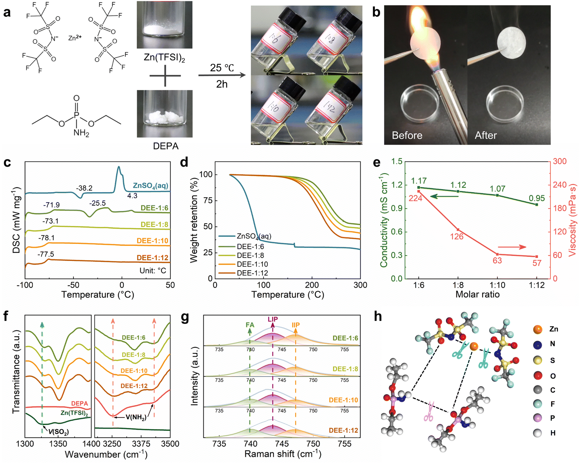
A series of stable DEEs were prepared by simply mixing Zn(TFSI)2 with low-melting-point (51–53 °C) DEPA and stirring at room temperature for 2 h (Fig. 1(a)). Based on different molar ratios of Zn(TFSI)2![[thin space (1/6-em)]](https://www.rsc.org/images/entities/char_2009.gif) :DEPA, these formulations are denoted as DEE-1:m (m = 6, 8, 10, 12). Due to the nonflammable nature of DEPA, the flammability test of DEE confirms its stability and safety under open flame lighter (Fig. 1(b)). Notably, DEEs at all ratios can still maintain a liquid state at −20 °C (Fig. S1, ESI†). The glass transition temperatures (Tg) of DEEs obtained from differential scanning calorimetry (DSC) tests are below −70 °C (Fig. 1(c)). When the DEPA content increases, the freezing/melting peaks of DEEs disappear, suggesting the formation of eutectic electrolyte that is stable at low temperatures. Thermogravimetric analysis (TGA) further supported the thermal stability of DEEs (Fig. 1(d)). Even when heated up to 160 °C, the weight loss of DEEs remains minimal, ranging from 2.17% (DEE-1:6) to 4.75% (DEE-1:12); whereas, the water in aqueous electrolyte evaporates completely even below 100 °C. The excellent thermal properties open the possibility of utilizing this eutectic system in a wide temperature range. Additionally, the Zn(TFSI)2:DEPA molar ratios were optimized to balance the high ion conductivity and low viscosity. The DEE-1:10 exhibits relatively high conductivity (1.07 mS cm−1@25 °C) coupled with relatively low viscosity (63 mPa s) (Fig. 1(e) and Table S1, ESI†).
:DEPA, these formulations are denoted as DEE-1:m (m = 6, 8, 10, 12). Due to the nonflammable nature of DEPA, the flammability test of DEE confirms its stability and safety under open flame lighter (Fig. 1(b)). Notably, DEEs at all ratios can still maintain a liquid state at −20 °C (Fig. S1, ESI†). The glass transition temperatures (Tg) of DEEs obtained from differential scanning calorimetry (DSC) tests are below −70 °C (Fig. 1(c)). When the DEPA content increases, the freezing/melting peaks of DEEs disappear, suggesting the formation of eutectic electrolyte that is stable at low temperatures. Thermogravimetric analysis (TGA) further supported the thermal stability of DEEs (Fig. 1(d)). Even when heated up to 160 °C, the weight loss of DEEs remains minimal, ranging from 2.17% (DEE-1:6) to 4.75% (DEE-1:12); whereas, the water in aqueous electrolyte evaporates completely even below 100 °C. The excellent thermal properties open the possibility of utilizing this eutectic system in a wide temperature range. Additionally, the Zn(TFSI)2:DEPA molar ratios were optimized to balance the high ion conductivity and low viscosity. The DEE-1:10 exhibits relatively high conductivity (1.07 mS cm−1@25 °C) coupled with relatively low viscosity (63 mPa s) (Fig. 1(e) and Table S1, ESI†).
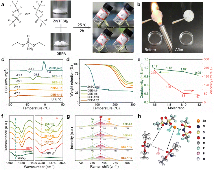 |
| | Fig. 1 Physicochemical properties and spectral analysis of DEEs. (a) Preparation strategy of DEEs based on Zn(TFSI)2 and DEPA. (b) Flammability test of separator soaked by DEE under open flame lighter. (c) DSC curves of ZnSO4 aqueous electrolyte and DEEs with different Zn(TFSI)2:DEPA molar ratios from −100 °C to 50 °C. (d) TGA results of ZnSO4 aqueous electrolyte and different DEEs. (e) Ionic conductivity and viscosity of different DEEs. (f) FTIR spectra: ν(SO2) and ν(NH2). (g) Fitted Raman spectra of DEEs with different molar ratios. (h) Illustration of the interaction among Zn2+, TFSI− and DEPA in DEEs. | |
The interaction between DEE components was studied by Fourier transform infrared (FTIR) spectroscopy (Fig. 1(f) and Fig. S2, S3,ESI†). The SO2 asymmetric stretching mode of TFSI− increases from 1326.9 cm−1 in pristine salt to 1350.1 cm−1 in DEEs. As the SO2 group is susceptible to Zn2+–DEPA and TFSI−–DEPA interactions, this peak shift can confirm the solvation of Zn2+ with DEPA solvent molecules.29–31 The peaks at 3253.7 cm−1 and 3419.5 cm−1 in pristine DEPA, corresponding to symmetric and asymmetric NH2 stretching, shift to 3348.2 cm−1 and 3421.5 cm−1 in DEEs, respectively, suggesting the disruption of hydrogen bonds between DEPA and the formation of new bonds with the salt.23,32 FTIR spectra also reveal a significant change in the PO group (1218.9 cm−1) of DEPA.33 The PO group undergoes a red shift with increasing salt concentration, potentially corresponding to metal–oxygen coordination between Zn2+ and the PO group. Raman spectra were used to detect the shift of SO2 group in Zn(TFSI)2 from the initial 1130.1 cm−1 to 1140.0 cm−1, and a slight shift of NH2 group in DEPA, indicating the interaction between two components (Fig. S4 and S5, ESI†).34 In addition, the existing environment of TFSI− is explored by comparing the change of ν(S–N–S) peak (∼749.5 cm−1) with salt concentration (Fig. 1(g)).35,36 The proportions of free anions (FAs), loose ion pairs (LIPs), and intimate ion pairs (IIPs) can be obtained separately (Fig. S6, ESI†). Decreasing the salt concentration, the FA proportions increase and the IIP proportions decrease, suggesting good dissociation of Zn2+ by the solvent molecules. The formation principle of this eutectic solution obtained from spectral analysis is then summarized in Fig. 1(h), that the salt–solvent interaction weakens the bonds among themselves and thereby forms a eutectic electrolyte.
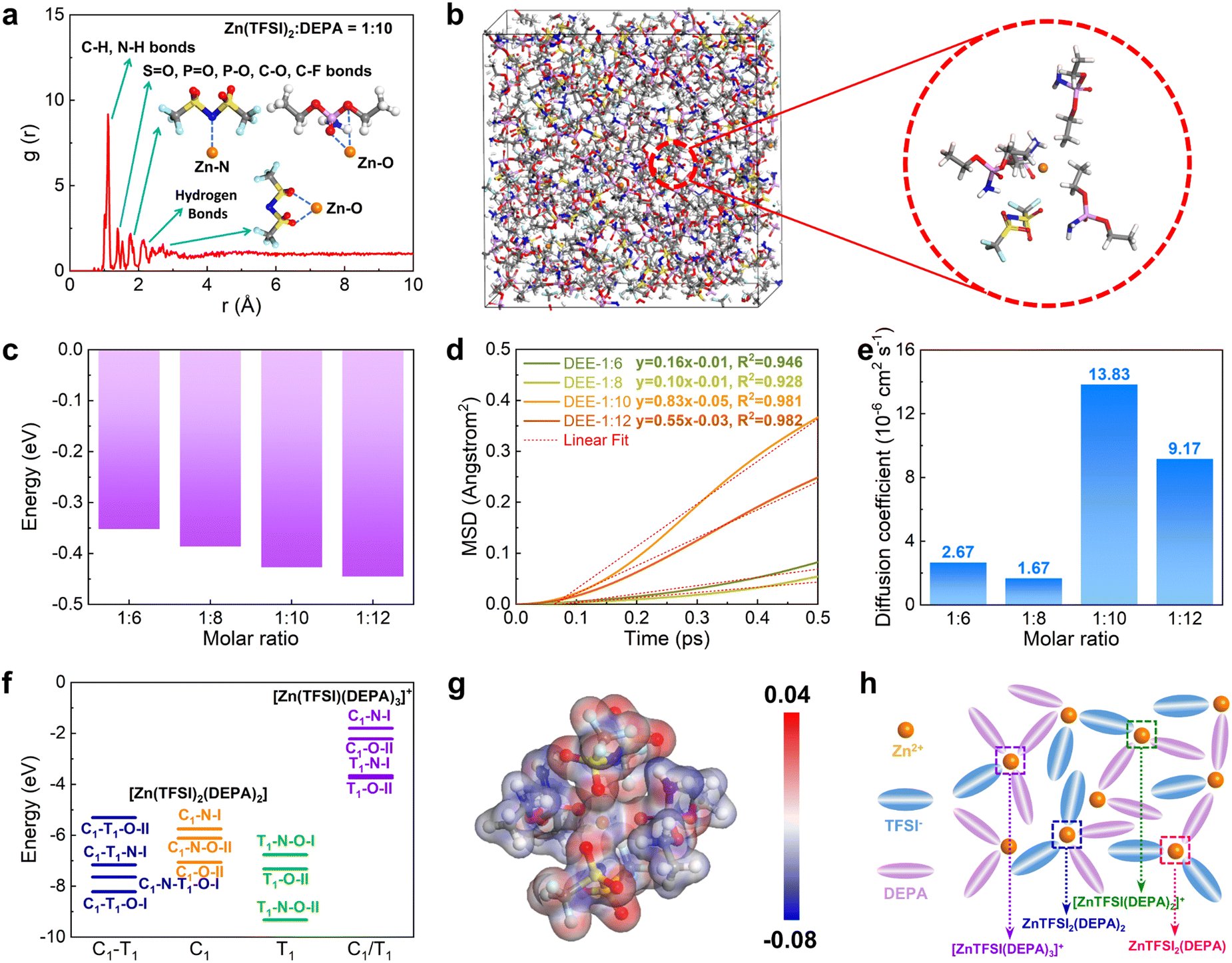
Then, DFT calculations and molecular dynamic (MD) simulations were further introduced to investigate the formation of DEEs. We constructed four different DEEs, i.e. DEE-1:6, 1:8, 1::10, and 1:12, respectively. Based on the radial distribution function (RDF), it is noted that all DEEs show similar peak distributions (Fig. 2(a) and Fig. S7, ESI†). There is an evident peak near 1.1 Å, which corresponds to a large amount of C–H and N–H bonds in DEEs. The second peak appears near 1.4 Å, which is attributed to the bonding with oxygen by different atoms including S, P, and C in both TFSI− and DEPA. For Zn2+, the closest coordination is formed within the distances near 1.8 Å, displaying the preferred coordination between Zn2+ and the PO group of DEPA. The hydrogen bonds between F, N, O, and H atoms are mostly located near 2.3 Å. For the interaction of Zn2+ with O from TFSI−, it exhibits a coordination distance near 2.3–2.6 Å. In the snapshot of DEE-1:10, it has been identified that Zn2+ is mostly preferred to locate near 1–2 TFSI− and there are usually 2–3 DEPA molecules in the coordination range (Fig. 2(b)). The increase in DEPA gradually modulates the coordination structure of Zn2+ (Fig. S8, ESI†). Notably, the interaction energies of DEEs gradually decrease as DEPA concentration increases, supporting that the introduction of DEPA facilitates the interaction with Zn2+ (Fig. 2(c)). To reveal the diffusion behavior of Zn2+, the mean square displacement (MSD) of different electrolytes was compared in the same period of 0.5 ps after 5000 MD simulation steps (Fig. 2(d)). All electrolytes show a relatively linear correlation of MSD with time, especially DEE-1:10 and DEE-1:12. It is noted that MSD displays a volcano trend. Based on the linear fit of MSD, the diffusion coefficients of Zn2+ are determined as 2.67 × 10⁻⁶, 1.67 × 10⁻⁶, 13.83 × 10⁻⁶, 9.17 × 10⁻⁶ cm2 s−1 for DEE-1:6, 1:8, 1:10, and 1:12, respectively (Fig. 2(e)). This indicates that DEEs are of the same order of magnitude overall, with DEE-1:10 supplying the most efficient Zn2+ migration. To further support this finding, we conducted electrochemical impedance spectroscopy (EIS) to assess the impedance characteristics of DEEs (Fig. S9, ESI†). The results indicate that although there are differences in the magnitude of diffusion coefficients obtained from EIS and theoretical calculations, the overall trend observed is consistent.
 |
| | Fig. 2 Theoretical calculation and Zn solvation structure in DEEs. (a) The RDF and (b) snapshot of DEE-1:10 after MD simulations. (c) Interaction energies of different DEEs. (d) MSD of Zn2+ and (e) diffusion coefficient comparisons in DEEs. (f) The stability comparisons of coordination configurations for [Zn(TFSI)2(DEPA)2] and [Zn(TFSI)(DEPA)3]+. C1 and T1 indicate the cisoid and transoid form of TFSI−, respectively. I: monodentate coordination of TFSI−. II: bidentate coordination of TFSI−. (g) Electron density difference demonstration of [Zn(TFSI)2(DEPA)2] (T1–N–O–II). (h) Schematic diagram of coordination structure in DEE. | |
To further understand the interaction between Zn2+ with TFSI− and DEPA, we have calculated their interaction energies in different geometry configurations, where both cisoid (C1) and transoid (T1) forms of TFSI− are considered with N and O as potential coordination sites for Zn2+ (Fig. 2(f) and Fig. S10, S11, ESI†).37–39 Since the electrolyte structures involve several layers around the cations, the calculations of different configurations are able to demonstrate the possible inner solvation structures near Zn2+ cations. For the coordination environments in [Zn(TFSI)2(DEPA)2] and [Zn(TFSI)(DEPA)3]+, it is found that the bidentate coordination of Zn2+ with T1-form TFSI− constitutes more energetically preferred configurations, among which [Zn(TFSI)2(DEPA)2] (T1–N–O–II) is the most stable one. Meantime, under the same coordination number (CN) of Zn2+, increasing the DEPA molecule numbers from 2 to 3 in the solvation structure significantly increases the overall interaction energies. Other possible solvation configurations with lower CN of Zn2+ have also been evaluated, such as [Zn(TFSI)2(DEPA)], [Zn(TFSI)(DEPA)2]+ and [Zn(TFSI)(DEPA)]+ (Fig. S12–S15, ESI†). By comparing the interaction energies of different coordination configurations, it is revealed that DEPA molecules and TFSI− anions both contribute to shaping the solvation structure, and a higher concentration of TFSI− facilitates the stabilization of Zn2+ coordination through the bidentate coordination. In the most stable [Zn(TFSI)2(DEPA)2] (T1–N–O–II), the nearby O and N sites point to Zn2+ with a distance around 1.8–2.3 Å, which is also consistent with the RDF results above. The electron density difference also indicates that the overall electron density is uniform among the whole T1–N–O–II configuration (Fig. 2(g)). Therefore, the solvation environment of Zn2+ in DEE is schematically illustrated in Fig. 2(h).
Uniform Zn nucleation and growth behavior guided by DEE
To systematically elucidate the advantages of DEE, the electrochemical window was measured using linear scanning voltammetry (LSV) tests (Fig. 3(a)). It is noted that the DEE-1:10 is selected as the optimum DEE for all the following electrochemical tests. The traditional ZnSO4 aqueous electrolyte shows a narrow electrochemical window due to the inevitable HER and oxygen evolution reaction (OER). Conversely, DEE simultaneously eliminates the effects of both HER and OER, demonstrating stability in a wide window of 3.00 V (vs. Zn/Zn2+). Tafel curves were measured using Zn foil as the working electrode to evaluate the self-corrosion behavior of Zn metal in two electrolytes (Fig. 3(b)). The smaller self-corrosion current and 96.5% corrosion-inhibition efficiency prove the robust corrosion resistance of Zn metal in DEE. To illustrate this corrosion inhibition effect more intuitively, pure Zn foils were soaked in two electrolytes for 10 days. Undesired (ZnSO4)(Zn(OH)2)3(H2O) byproducts are identified on the Zn surface in ZnSO4 aqueous electrolyte, but are absent on Zn soaked in DEE, confirming the improved self-corrosion resistance in eutectic electrolyte (Fig. S16, ESI†). Additionally, it can be found that the contact angle between DEE and Zn foil is 51°, significantly lower than the 88° observed between ZnSO4 electrolyte and Zn foil (Fig. S17, ESI†). As per the calculation formula, the reduced contact angle means a decrease in the interface free energy and an increase in the wetting degree of electrolyte on Zn electrode, thereby promoting the homogeneous distribution of Zn2+ flux and facilitating uniform Zn nucleation.40
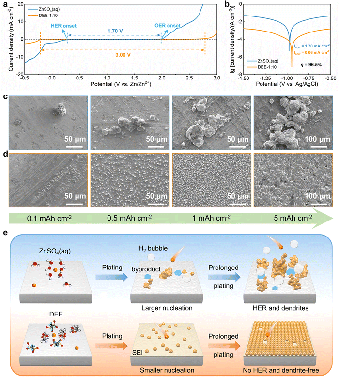 |
| | Fig. 3 Zn nucleation and growth behavior in electrolytes. (a) LSV curves of Zn–SS cells in DEE-1:10 and ZnSO4 aqueous electrolyte at 1 mV s−1. (b) Tafel curves of Zn foil tested in both electrolytes with a three-electrode system. SEM images of Zn nucleation and growth behavior at a current density of 2 mA cm−2 under different plating charge quantities (0.1–5 mA h cm−2) in (c) ZnSO4 aqueous electrolyte and (d) DEE-1:10. (e) Schematic diagram of Zn deposition in different electrolyte environments. | |
The nucleation and growth behavior of Zn in DEE was compared with that in traditional ZnSO4 aqueous electrolyte. Scanning electron microscopy (SEM) was used to characterize the morphological evolution of Zn deposits under different plating charge quantities (0.1–5 mA h cm−2) in two electrolytes. As depicted in Fig. 3(c), at a current density of 2 mA cm−2, Zn nuclei in aqueous electrolyte are relatively large, sparsely distributed, and irregular in shape. Even for a plating charge of 5 mA h cm−2, a complete film has not yet been formed. In contrast, Zn nuclei are small, compact, and evenly distributed in shape for DEE. As the nuclei grow, a dense Zn deposition layer eventually covers the substrate (Fig. 3(d)). Then, to comprehensively verify the positive effect of DEE on Zn electrocrystallization, Zn deposition morphology at a lower current rate of 0.1 mA cm−2 was investigated (Fig. S18, ESI†). It has been reported that side reactions, such as HER and self-corrosion, are more prominent at low current densities, thereby posing greater challenges to uniform and compact Zn nucleation behavior.41,42 This is confirmed by the more uneven Zn deposits in aqueous electrolyte at 0.1 mA cm−2; whereas, the Zn plating still maintains a uniform distribution and growth in DEE. According to the nucleation theory, the critical radius rc of a hexagonal nucleus can be obtained as43
| |  | (1) |
where
σ1 is the interfacial tension between the nucleus and electrolyte,
M is the relative atomic mass of Zn metal,
ρ is the density of Zn,
n is the number of electrons,
F is the Faraday constant, and
η is the overpotential. Therefore, a higher plating overpotential in DEE promotes finer and denser Zn nuclei (Fig. S19, ESI
†). Another reason is that the hydrogen gas evolution is suppressed and does not interfere Zn deposition. Therefore, Zn deposition behavior in two electrolytes can be schematically compared as
Fig. 3(e). The side reactions induced by water decomposition in aqueous electrolyte exacerbate its inherently uneven and rough nucleation behavior, ultimately leading to the notorious dendrites. Meantime, this HER side reaction also increases the local pH value, leading to the formation of byproducts ((ZnSO
4)(Zn(OH)
2)
3(H
2O),
etc.).
44 In contrast, DEE is not troubled by gas evolution and promotes the dense and uniform Zn deposition. Furthermore, this DEE could also lead to the formation of a protective SEI layer as will be discussed thereafter.
Interface chemistry induced by DEE
As is well known, the derived SEI layer plays a fundamental role in achieving stable and efficient lithium-ion batteries.45–47 Recently, it has been proven that the stability of ZMBs can be enhanced by introducing SEI layers on Zn electrode, which is mostly formed by the decomposition of anions or solvents.48,49 However, the direct reduction of free TFSI− shows a lower potential of −1.08 V (vs. Zn/Zn2+), indicating that it can hardly be decomposed before Zn2+ reduction (Fig. S20, ESI†). And the reduction potential of coordinated TFSI− with Zn2+ has been significantly increased to 0.39 V and 0.69 V (vs. Zn/Zn2+) for Zn(TFSI) and Zn(TFSI)2, respectively. As discussed above, TFSI− participates in the solvation structure of Zn2+ in DEE, so the preferential decomposition of solvated TFSI− can contribute to the SEI formation.
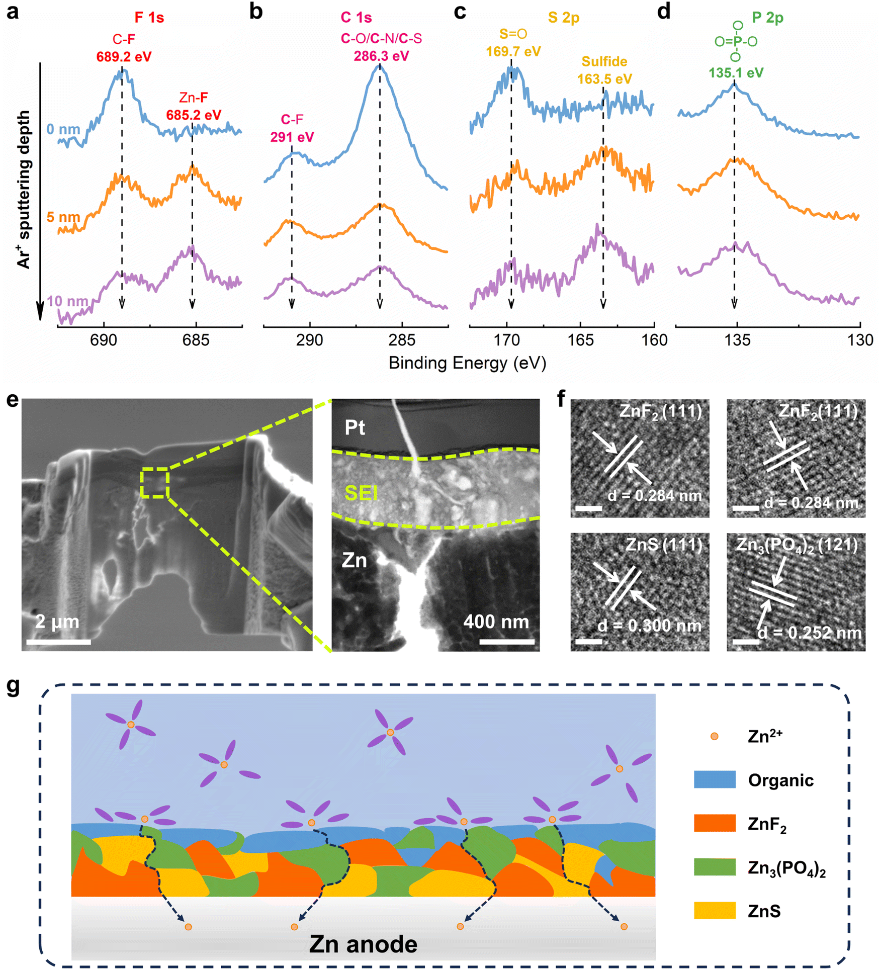
Then, Zn metal electrode was plated/stripped in DEE and dissembled for surface characterizations. Initially, in-depth X-ray photoelectron spectroscopy (XPS) combined with Ar+ sputtering was used to detect the Zn anode after cycling. High resolution spectra of multiple elements are obtained at different sputtering depths, confirming that the decomposition of DEE components forms a SEI layer on the electrode surface.50–52 In the F 1s spectrum, a signal at 689.2 eV corresponding to the C–F bond appears on Zn electrode surface, while the Zn–F bond at 685.2 eV under deep sputtering arises from the decomposition of TFSI−, indicating that the inner layer of SEI is rich in ZnF2 (Fig. 4(a)). The C 1s spectrum reveals peaks at 291 eV and 286.3 eV, attributed to C–F bond and C–O/C–/C–S bond, respectively (Fig. 4(b)). These peak signals weaken with increasing depth, suggesting that organic components dominate the outer layer of SEI. In the S 2p spectrum, a new peak at 163.5 eV assigned to sulfide is detected, where the peak signal further enhances with increasing depth, indicating that the SEI inner layer is abundant in inorganic sulfur (Fig. 4(c)). The P 2p spectrum exhibits a peak at 135.1 eV, corresponding to PO4 derived from the decomposition of DEPA (Fig. 4(d)). XPS analysis results have demonstrated that the electrolyte decomposes on electrode surface, forming a hybrid SEI with an inorganic-rich inner layer and an organic-rich outer layer.
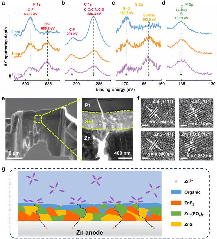 |
| | Fig. 4 Interface chemistry between the electrolyte and Zn anode. In-depth XPS spectra of (a) F 1s, (b) C 1s, (c) S 2p and (d) P 2p on Zn anode after 50 cycles in DEE-1:10. (e) FESEM and TEM images of Zn anode cycling in DEE-1:10 after FIB cutting. The Pt layer is used to shield SEI from damage by ion beam. (f) HRTEM images of Zn anode after cycling in DEE-1:10. Scale bar, 1 nm. (g) The organic–inorganic-coupled SEI induced by DEE system on Zn anode. | |
In addition, transmission electron microscopy (TEM) was used to observe Zn anode cycling in DEE after focused ion beam (FIB) cutting, identifying a distinct SEI layer at the top of Zn substrate (Fig. 4(e)). The high-resolution TEM (HRTEM) image of electrode cross-section directly reveals the SEI structure (Fig. S21, ESI†). The analysis in Fig. 4(f) confirms that the lattice fringes correspond to ZnF2, ZnS, and Zn3(PO4)2, respectively. As illustrated in Fig. 4(g), a schematic diagram outlines the composition of SEI layer. Moreover, the formation mechanism of the organic–inorganic-coupled SEI layer is reflected by chemical reaction eqn (2)–(8). When a complete SEI layer is generated, solvated Zn2+ diffuses from electrolyte to SEI surface and undergoes desolvation during plating. Subsequently, it permeates within SEI layer and ultimately reaches Zn anode to complete the deposition reaction. It is emphasized that this organic–inorganic-coupled SEI layer is robust and can prevent uncontrollable and continuous occurrence of side reactions, thereby improving Zn anode stability and guiding Zn plating/stripping reaction.
| | | NSO2CF32− + e− → NSO22− + CF3− | (2) |
| | | NSO22− + e− → S2− + NO2− | (3) |
| | | DEPA + 3e− → PO43− + organic | (5) |
| | | 3Zn2+ + 2PO43− → Zn3(PO4)2 | (8) |
Electrochemical performance of Zn anode enhanced by DEE
To explore the benefits of DEE on Zn anode stability, ZnSO4 aqueous electrolyte and DEE were compared in Zn–Zn symmetric cells. Firstly, considering the exacerbated side reactions under a very low current density, a testing condition of 0.1 mA cm−2 with 0.1 mA h cm−2 was adopted. The cell in ZnSO4 aqueous electrolyte displays a polarization voltage of 40 mV and a limited cycle life of only 245 h (Fig. 5(a)). However, the symmetric cell using DEE can operate stably for 12000 h (over one year). At a higher current density of 1 mA cm−2 and an areal capacity of 1 mA h cm−2, DEE can achieve a cycle life of 1200 h (Fig. 5(b)). Compared with published work on other electrolytes, this study is outstanding in the long-term cycling stability of symmetric cells (Table S2, ESI†).6,14,15,18,19,23,24,26–28 Additionally, cycling tests were conducted at current densities of 0.1–5 mA cm−2 to evaluate the rate performance of symmetric cells in both electrolytes. The cell in ZnSO4 electrolyte exhibits notable voltage fluctuations (Fig. S22, ESI†). On the contrary, DEE supports stable battery operation under both high and low current densities (Fig. 5(c)). Furthermore, the Zn plating/stripping coulombic efficiency and cycling life in Zn–Cu cells with DEE have also been demonstrated to be much superior over those with aqueous electrolyte (Fig. S23 and S24, ESI†). Subsequently, SEM was employed to characterize the morphological changes of Zn anode after cycling in two electrolytes (Fig. 5(d)). It can be observed that the electrode surface in ZnSO4 electrolyte is rough after 10 cycles, with uneven and dendritic Zn distribution. This phenomenon becomes more severe after 100 cycles, resulting in battery failure. In stark contrast, Zn electrode in DEE maintains a smooth surface after 10 and 100 cycles without harmful dendrites. The corresponding XRD patterns further confirm that HER-derived byproducts appear on Zn electrode in ZnSO4 electrolyte, but are absent on Zn electrode in DEE (Fig. S25, ESI†).
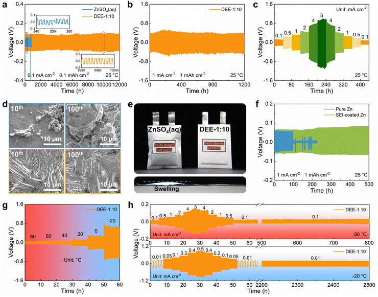 |
| | Fig. 5 The effects of DEE on electrochemical performance of Zn anode. Long-term cycling performance of Zn–Zn symmetric cells at (a) 0.1 mA cm−2 with 0.1 mA h cm−2 and (b) 1 mA cm−2 with 1 mA h cm−2. (c) Rate performance of symmetric cell in DEE-1:10 at current densities of 0.1–5 mA cm−2. (d) SEM images of Zn anode after 10 (left) and 100 (right) cycles in ZnSO4 aqueous electrolyte (up), DEE-1:10 (down). (e) Optical images of Zn–Zn pouch cells after cycling in two electrolytes. (f) Cycling performance of symmetric cells with pure Zn and SEI-coated Zn foil in ZnSO4 aqueous electrolyte at 1 mA cm−2. Voltage profiles of symmetric cells in DEE-1:10 with the temperature of (g) 80 °C to −20 °C and (h) 80 °C and −20 °C. | |
The hydrogen production in two different electrolytes could be compared more intuitively (Fig. 5(e)). As expected, when the cumulative capacity reaches 100 mA h cm−2, the pouch cell with ZnSO4 aqueous electrolyte generates a large amount of gas and exhibits accident-prone swelling. The pouch cell in DEE shows no signs of gas generation and remains in pristine condition. This phenomenon directly supports the suppressive effect of DEE on HER, which is consistent with previous research results. To confirm the robustness of SEI layer formed in situ by DEE, Zn electrode was first cycled in DEE, and then assembled in symmetric cells with ZnSO4 aqueous electrolyte (Fig. 5(f) and Fig. S26, ESI†). It is found that the Zn plating/stripping cycle life can still be significantly prolonged, comparing to that without the pre-treatment. Therefore, the organic–inorganic-coupled SEI layer is demonstrated to be robust even in the strong polar aqueous electrolyte and provide effective Zn2+ transport. The EIS results indicate that the cell with SEI layer exhibits lower impedance compared with the cell constructed with pure Zn (Fig. S27, ESI†). This once again confirms that the stable SEI layer can promote smooth ion transport at the interface and reduce the charge transfer resistance.
Given that DEE is stable in a wide temperature window, the Zn plating/stripping performance at high and low temperatures was evaluated. As illustrated in Fig. 5(g), the cell with DEE maintains a consistent voltage response in the wide temperature range of −20 °C to 80 °C. Meanwhile, the cell in DEE is stably cycled at 80 °C, displaying superior rate performance and cycling performance compared to ZnSO4 aqueous electrolyte (Fig. 5(h) and Fig. S28, ESI†). Similarly, at a low temperature of −20 °C, the cell in aqueous electrolyte experiences abnormal polarization and cannot even operate for 1 h, while DEE enables the cell to achieve a long cycle life of 2500 h (Fig. S29, ESI†). In short summary, the prolonged Zn plating/stripping cycle life is proven in DEE due to the avoided HER, robust SEI layer and compact Zn growth. The superior advantages of DEE over aqueous electrolyte in a wide temperature window have also been confirmed.
Cycling stability and practicality of ZMBs in DEE
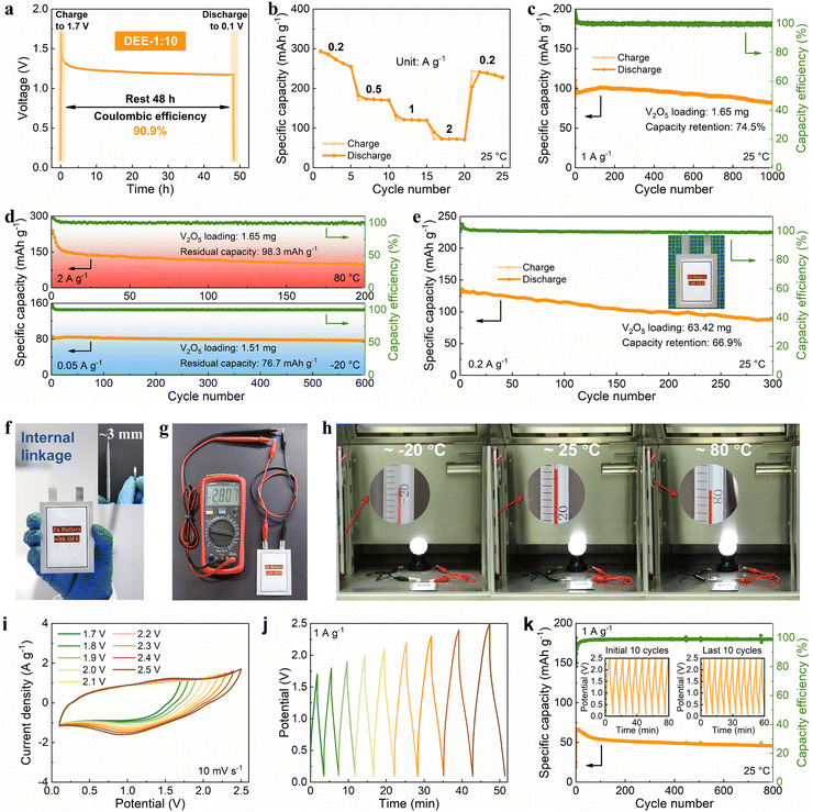
Then, the viability of DEE was evaluated in Zn–V2O5 full cells. Initially, the solid–liquid contact angle between V2O5 cathode and two electrolytes was tested. Notably, the contact angle between DEE and V2O5 cathode is only 24° (much lower than the 113° of ZnSO4 aqueous electrolyte), signifying excellent wettability of the cathode by DEE with a lower interface free energy (Fig. S30, ESI†).40 The superiority of DEE was further highlighted by comparing the self-discharge resistance of Zn–V2O5 full cells in two electrolytes. It can be observed that following a 48-hour standing period, the full cell in ZnSO4 electrolyte only retains 75.1% of its initial capacity, significantly lower than the 90.9% retention in DEE (Fig. 6(a) and Fig. S31, ESI†). Furthermore, the full cell in DEE was measured at 0.2, 0.5, 1, and 2 A g−1, yielding discharge capacities of 273.4, 172.0, 120.5, and 72.7 mA h g−1, respectively. Even when the current density returns to 0.2 A g−1, a capacity of 237.8 mA h g−1 can still be recovered, demonstrating excellent rate performance (Fig. 6(b)). The galvanostatic charge–discharge (GCD) curves at different current densities are presented in Fig. S32 (ESI†). At a current density of 1 A g−1, Zn–V2O5 full cell using DEE can operate stably for 1000 cycles (Fig. 6(c)). Considering the above-mentioned challenges at low current densities, an attempt was made to evaluate the effectiveness of DEE on Zn–V2O5 full cell under corresponding conditions. Remarkably, the full cell can still maintain a capacity of 170.4 mA h g−1 after 300 cycles at 0.2 A g−1 and a capacity retention rate of 78.0% after 300 cycles at 0.5 A g−1 (Fig. S33, ESI†). Simultaneously, the GCD curves under different cycles exhibits consistent charge–discharge platforms at high and low current densities (Fig. S34, ESI†). However, the capacity retention rate of Zn–V2O5 full cell in ZnSO4 aqueous electrolyte is only 10.8% after 300 cycles at 0.2 A g−1 (Fig. S35, ESI†). Although aqueous electrolyte includes additional H+ insertion process that is not present in DEE and exhibits higher initial capacity, the rapid decrease in stability as the reaction progresses offsets this advantage of aqueous electrolyte. Additionally, the CE in the aqueous electrolyte begins to fluctuate after 320 cycles at 1 A g−1, which may be caused by side reactions on the electrode side and uneven Zn deposition. To further demonstrate the application potential of DEE, the performance of Zn–V2O5 full cell with DEE was tested over a wide temperature range. When the temperature increases to 80 °C, an initial capacity decay is observed due to the accelerated chemical reactions induced by the elevated temperature.53–55 However, over time, the thermal stability of DEE contributes to the stable operation of Zn–V2O5 full cell at the high temperature (Fig. 6(d)). Furthermore, even when the temperature changes to −20 °C, the full cell in DEE can operate stably for 600 cycles with a residual capacity of 76.7 mA h g−1.
 |
| | Fig. 6 Cycling stability and practicality of the DEE-based energy storage. (a) Self-discharge resistance, (b) rate performance, and (c) cycling performance of Zn–V2O5 full cell. (d) Long-term cycling performance of Zn–V2O5 full cell with temperatures of 80 °C and −20 °C. (e) Cycling performance of Zn–V2O5 pouch cell at 0.2 A g−1. (f) Optical image of a pouch cell in internal linkage (with a thickness equivalent to that of a coin cell). (g) The voltage of 2.807 V provided by an internally series-connected pouch cell. (h) The series-connected pouch cell to drive a night light at temperatures of −20 °C, 25 °C, and 80 °C. (i) CV and (j) GCD curves of Zn-ion hybrid capacitor with different operating windows. (k) Long-term cycling performance of the capacitor with the operating window ranging from 0.1 V to 2.5 V. | |
Given the significant electrochemical performance endowed by DEE in coin cells, Zn–V2O5 pouch cells were further assembled. Notably, DEE can sustain the pouch cell to a long lifespan of 300 cycles, with a capacity of 130.1 mA h g−1 and a retention rate of 66.9% (Fig. 6(e)). To clarify safety, comprehensive safety tests were conducted on Zn–V2O5 pouch cell. Obviously, after being pricked and cut, the pouch cell can still power the calculator without any short circuit or combustion, underscoring the astonishing safety provided by this new electrolyte (Fig. S36, ESI†). As the operating voltage of ZMBs is lower than other metal batteries, a series connection is designed to obtain ZMBs that can participate in industrial competition.56,57 Unlike the series connection using external wires in other works, the internal linkage is employed to achieve more flexible and thinner pouch cells with a thickness equivalent to that of a coin cell (Fig. 6(f)). At the same time, this series-connected pouch cell can provide a stable voltage of 2.807 V (Fig. 6(g)). Surprisingly, owing to the excellent stability of DEE across a wide temperature range, the corresponding series-connected pouch cell can supply energy to a night light for more than 3 minutes at temperatures of −20 °C, 25 °C, and 80 °C, respectively (Fig. 6(h), Fig. S37 and Video S1, ESI†).
To fully demonstrate the high-voltage tolerance of DEE, Zn-ion hybrid capacitors were prepared using commercial activated carbon as cathode, Zn foil as anode, and DEE as electrolyte. The capacitors were firstly evaluated by cyclic voltammetry (CV) and GCD technique. As is shown in Fig. 6(i), the CV profiles present a quasi-rectangle shape without any polarization trend when the voltage window is extended to 2.5 V. Besides, when working voltage is set from 0.1 V to 2.5 V, the CV curves at a high scan rate to 100 mV s−1 can still retain a quasi-rectangular shape with little distortion (Fig. S38, ESI†). Similarly, the GCD curves for different operating voltage windows maintain an approximately triangular shape up to 0.1–2.5 V, and display no significant IR drop at the beginning of discharging (Fig. 6(j)). Such results demonstrate that an electrochemical system using DEE as electrolyte can be operated stably over at least 0.1 V to 2.5 V, which is significantly higher than that below 2 V with the aqueous electrolyte (Fig. S39, ESI†). Specifically, the long-term cycling performance of Zn-ion hybrid capacitors at 1 A g−1 over a wide operating voltage window (0.1–2.5 V) is shown in Fig. 6(k), which reveals 71.2% capacity retention after 800 cycles with high coulombic efficiency. The insets further provide the GCD of the first and the last ten cycles, showing small variations before and after long-term cycling. These results, combined with DEE's superb performance in ZMBs, confirm the wide temperature and electrochemical windows of DEE in the field of energy storage, exceeding most of currently reported electrolytes, particularly under harsh working conditions (Table S3, ESI†).6,14,15,18,19,28,53–55,58–61
Conclusions
In summary, we present a nonflammable eutectic electrolyte with combined advantages, including the wide electrochemical window of 3.0 V (vs. Zn/Zn2+), wide thermal-stability window (about −70 °C to 160 °C). The formation mechanism and solvation structure of DEE have been investigated experimentally and theoretically. Importantly, due to its excellent physicochemical properties, DEE has been demonstrated to eliminate hydrogen evolution, induce a robust organic–inorganic-coupled SEI layer, and promote compact Zn nucleation behavior, solving the corresponding issues in counterpart aqueous electrolyte. Impressively, the DEE also endows the stable Zn plating/stripping in Zn–Zn symmetric cells and Zn–V2O5 full cells over a wide temperature range of −20 °C to 80 °C. Furthermore, DEE enables an operating window of 0.1 V to 2.5 V for the Zn-ion capacitor. Our work presents a promising electrolyte for high-performance practical energy storage.
Author contributions
X. B. and X. P. designed this study. X. B. conducted characterization analysis and all electrochemical measurements. M. S. and B. H. performed DFT calculations and molecular dynamic simulations. J. Y. analyzed the spectra and TEM data. B. D. organized the capacitor testing. K. Y. synthesized the cathode material. X.B. wrote the manuscript with the assistance of X. P., W. H., M. S., and B. D.
Data availability
The data supporting this article have been included as part of the ESI.†
Conflicts of interest
The authors have a patent document to disclose. X. P. and X. B. are inventors of a CN patent application (no. CN116706210A) concerning the preparation and application of eutectic electrolytes for secondary batteries described herein.
Acknowledgements
This work was supported by the National Natural Science Foundation of China (grant no. 52173274, 52303367, 82201023, 52173298, 52192611, and 61904012), the National Key R&D Project from Minister of Science and Technology (2021YFA1201603, 2021YFA1501101), Beijing Natural Science Foundation (Z230024), and the Fundamental Research Funds for the Central Universities, Research Grant Council of Hong Kong (15304023), National Natural Science Foundation of China/Research Grant Council of Hong Kong Joint Research Scheme (N_PolyU502/21), National Natural Science Foundation of China/Research Grants Council of Hong Kong Collaborative Research Scheme (CRS_PolyU504/22). B. H. also thanks the support from Research Centre for Carbon-Strategic Catalysis (RC-CSC), Research Institute for Smart Energy (RISE), and Research Institute for Intelligent Wearable Systems (RI-IWEAR) of the Hong Kong Polytechnic University.
References
- M. Armand and J. M. Tarascon, Nature, 2008, 451, 652–657 CrossRef CAS PubMed.
- L. Shan, Y. Wang, S. Liang, B. Tang, Y. Yang, Z. Wang, B. Lu and J. Zhou, InfoMat, 2021, 3, 1028–1036 CrossRef CAS.
- C. Huang, X. Zhao, Y. Hao, Y. Yang, Y. Qian, G. Chang, Y. Zhang, Q. Tang, A. Hu and X. Chen, Energy Environ. Sci., 2023, 16, 1721–1731 RSC.
- M. Wu, G. Zhang, H. Yang, X. Liu, M. Dubois, M. A. Gauthier and S. Sun, InfoMat, 2022, 4, e12265 CrossRef CAS.
- Z. Chen, F. Mo, T. Wang, Q. Yang, Z. Huang, D. Wang, G. Liang, A. Chen, Q. Li, Y. Guo, X. Li, J. Fan and C. Zhi, Energy Environ. Sci., 2021, 14, 2441–2450 RSC.
- W. H. Yang, X. F. Du, J. W. Zhao, Z. Chen, J. J. Li, J. Xie, Y. J. Zhang, Z. L. Cui, Q. Y. Kong, Z. M. Zhao, C. G. Wang, Q. C. Zhang and G. L. Cui, Joule, 2020, 4, 1557–1574 CrossRef CAS.
- Q. Zhang, Y. Ma, Y. Lu, Y. Ni, L. Lin, Z. Hao, Z. Yan, Q. Zhao and J. Chen, J. Am. Chem. Soc., 2022, 144, 18435–18443 CrossRef CAS PubMed.
- C. J. Xu, B. H. Li, H. D. Du and F. Y. Kang, Angew. Chem., Int. Ed., 2012, 51, 933–935 CrossRef CAS PubMed.
- J. Meng, X. Yao, X. Hong, L. Zhu, Z. Xiao, Y. Jia, F. Liu, H. Song, Y. Zhao and Q. Pang, Nat. Commun., 2023, 14, 3909 CrossRef CAS PubMed.
- H. Xu, R. Hu, H. Yan, B. Li, Z. Cao, Z. Du, Y. Gong, S. Yang and B. Li, ACS Energy Lett., 2022, 7, 3761–3769 CrossRef CAS.
- C. Huang, X. Zhao, S. Liu, Y. Hao, Q. Tang, A. Hu, Z. Liu and X. Chen, Adv. Mater., 2021, 33, 2100445 CrossRef CAS PubMed.
- M. Song and C. L. Zhong, Rare Met., 2022, 41, 356–360 CrossRef CAS.
- S. Chen, D. Ji, Q. Chen, J. Ma, S. Hou and J. Zhang, Nat. Commun., 2023, 14, 3526 CrossRef CAS PubMed.
- Y. Wang, R. Zhao, M. Liu, J. Yang, A. Zhang, J. Yue, C. Wu and Y. Bai, Adv. Energy Mater., 2023, 13, 2302707 CrossRef CAS.
- M. M. Wu, X. C. Wang, F. Zhang, Q. Xiang, Y. Li and J. X. Guo, Energy Environ. Sci., 2024, 17, 619–629 RSC.
- F. Wang, O. Borodin, T. Gao, X. Fan, W. Sun, F. Han, A. Faraone, J. A. Dura, K. Xu and C. Wang, Nat. Mater., 2018, 17, 543–549 CrossRef CAS PubMed.
- S. Chen, R. Lan, J. Humphreys and S. Tao, Energy Storage Mater., 2020, 28, 205–215 CrossRef.
- C. Zhang, W. Shin, L. D. Zhu, C. Chen, J. C. Neuefeind, Y. K. Xu, S. I. Allec, C. Liu, Z. X. Wei, A. Daniyar, J. X. Jiang, C. Fang, P. A. Greaney and X. L. Ji, Carbon Energy, 2021, 3, 339–348 CrossRef CAS.
- B. W. Olbasa, C. J. Huang, F. W. Fenta, S. K. Jiang, S. A. Chala, H. C. Tao, Y. Nikodimos, C. C. Wang, H. S. Sheu, Y. W. Yang, T. L. Ma, S. H. Wu, W. N. Su, H. Dai and B. J. Hwang, Adv. Funct. Mater., 2022, 32, 2103959 CrossRef CAS.
- A. P. Abbott, G. Capper, D. L. Davies, R. K. Rasheed and V. Tambyrajah, Chem. Commun., 2003, 70–71 RSC.
- S. Wang, G. Liu, W. Wan, X. Li, J. Li and C. Wang, Adv. Mater., 2024, 36, 2306546 CrossRef CAS PubMed.
- J. Wang, H. Qiu, Q. Zhang, X. Ge, J. Zhao, J. Wang, Y. Ma, C. Fan, X. Wang, Z. Chen, G. Li and G. Cui, Energy Storage Mater., 2023, 58, 9–19 CrossRef.
- H. Qiu, X. Du, J. Zhao, Y. Wang, J. Ju, Z. Chen, Z. Hu, D. Yan, X. Zhou and G. Cui, Nat. Commun., 2019, 10, 5374 CrossRef PubMed.
- D. Han, C. Cui, K. Zhang, Z. Wang, J. Gao, Y. Guo, Z. Zhang, S. Wu, L. Yin, Z. Weng, F. Kang and Q. H. Yang, Nat. Sustain., 2022, 5, 205–213 CrossRef.
- J. Hao, L. Yuan, Y. Zhu, X. Bai, C. Ye, Y. Jiao and S. Z. Qiao, Angew. Chem., Int. Ed., 2023, 62, e202310284 CrossRef CAS PubMed.
- W. Li, W. Kong, W. Liu, S. Xu, H. Zhu, S. Liu, W. Yu and Z. Wen, Energy Storage Mater., 2024, 65, 103103 CrossRef.
- L. Geng, J. Meng, X. Wang, C. Han, K. Han, Z. Xiao, M. Huang, P. Xu, L. Zhang, L. Zhou and L. Mai, Angew. Chem., Int. Ed., 2022, 61, e202206717 CrossRef CAS PubMed.
- F. Ming, Y. Zhu, G. Huang, A. H. Emwas, H. Liang, Y. Cui and H. N. Alshareef, J. Am. Chem. Soc., 2022, 144, 7160–7170 CrossRef CAS PubMed.
- T. T. A. Dinh, T. T. K. Huynh, L. T. M. Le, T. T. T. Truong, O. H. Nguyen, K. T. T. Tran, M. V. Tran, P. H. Tran, W. Kaveevivitchai and P. M. L. Le, ACS Omega, 2020, 5, 23843–23853 CrossRef CAS PubMed.
- R. A. Silva, G. Goulart Silva, C. A. Furtado, R. L. Moreira and M. A. Pimenta, Electrochim. Acta, 2001, 46, 1493–1498 CrossRef CAS.
- Y. Hu, Z. Wang, H. Li, X. Huang and L. Chen, Spectrochim. Acta, Part A, 2005, 61, 403–411 CrossRef PubMed.
- C. F. Araujo, J. A. P. Coutinho, M. M. Nolasco, S. F. Parker, P. J. A. Ribeiro-Claro, S. Rudić, B. I. G. Soares and P. D. Vaz, Phys. Chem. Chem. Phys., 2017, 19, 17998–18009 RSC.
-
V. Rai, B. R. Sekhar, D. Phase and S. Deb, arXiv, preprint, 2014, arXiv:1406.4686 DOI:10.48550/arXiv.1406.4686.
- H. Liang, H. Li, Z. Wang, F. Wu, L. Chen and X. Huang, J. Phys. Chem. B, 2001, 105, 9966–9969 CrossRef CAS.
- A. Bakker, S. Gejji, J. Lindgren, K. Hermansson and M. M. Probst, Polymer, 1995, 36, 4371–4378 CrossRef CAS.
- L. N. Sim, R. Yahya and A. K. Arof, Opt. Mater., 2016, 56, 140–144 CrossRef CAS.
- Q. Zhou, P. D. Boyle, L. Malpezzi, A. Mele, J. H. Shin, S. Passerini and W. A. Henderson, Chem. Mater., 2011, 23, 4331–4337 CrossRef CAS.
- Y. Liu, L. Xu, Y. Yu, M. He, H. Zhang, Y. Tang, F. Xiong, S. Gao, A. Li, J. Wang, S. Xu, D. Aurbach, R. Zou and Q. Pang, Joule, 2023, 7, 2074–2091 CrossRef CAS.
- J. Song, Y. Si, W. Guo, D. Wang and Y. Fu, Angew. Chem., Int. Ed., 2021, 60, 9881–9885 CrossRef CAS PubMed.
- C. W. Extrand, Langmuir, 2003, 19, 646–649 CrossRef CAS.
- J. Zhao, J. Zhang, W. Yang, B. Chen, Z. Zhao, H. Qiu, S. Dong, X. Zhou, G. Cui and L. Chen, Nano Energy, 2019, 57, 625–634 CrossRef CAS.
- X. Xu, S. Li, H. Yan, J. Du, S. Yang and B. Li, Adv. Funct. Mater., 2024, 34, 2308661 CrossRef CAS.
- J. Zhang, W. Huang, L. Li, C. Chang, K. Yang, L. Gao and X. Pu, Adv. Mater., 2023, 35, 2300073 CrossRef CAS PubMed.
- Y. Lv, M. Zhao, Y. Du, Y. Kang, Y. Xiao and S. Chen, Energy Environ. Sci., 2022, 15, 4748–4760 RSC.
- L. Cheng, Y. Wang, J. Yang, M. Tang, C. Zhang, Q. Zhu, S. Wang, Y. Li, P. Hu and H. Wang, Adv. Funct. Mater., 2023, 33, 2212349 CrossRef CAS.
- J. Liu, B. Yuan, N. He, L. Dong, D. Chen, S. Zhong, Y. Ji, J. Han, C. Yang, Y. Liu and W. He, Energy Environ. Sci., 2023, 16, 1024–1034 RSC.
- Q. Wang, C. Zhao, J. Wang, Z. Yao, S. Wang, S. G. H. Kumar, S. Ganapathy, S. Eustace, X. Bai, B. Li and M. Wagemaker, Nat. Commun., 2023, 14, 440 CrossRef CAS PubMed.
- D. Wang, D. Lv, H. Peng, C. Wang, H. Liu, J. Yang and Y. Qian, Angew. Chem., Int. Ed., 2023, 62, e202310290 CrossRef CAS PubMed.
- C. Chang, S. Hu, T. Li, F. Zeng, D. Wang, S. Guo, M. Xu, G. Liang, Y. Tang, H. Li, C. Han and H. M. Cheng, Energy Environ. Sci., 2024, 17, 680–694 RSC.
- S. Liu, J. Mao, W. K. Pang, J. Vongsvivut, X. Zeng, L. Thomsen, Y. Wang, J. Liu, D. Li and Z. Guo, Adv. Funct. Mater., 2021, 31, 2104281 CrossRef CAS.
- J. Xu, X. Ji, J. Zhang, C. Yang, P. Wang, S. Liu, K. Ludwig, F. Chen, P. Kofinas and C. Wang, Nat. Energy, 2022, 7, 186–193 CrossRef CAS.
- Y. Dong, N. Zhang, Z. Wang, J. Li, Y. Ni, H. Hu and F. Cheng, J. Energy Chem., 2023, 83, 324–332 CrossRef CAS.
- C. Xie, S. Liu, W. Zhang, H. Ji, S. Chu, Q. Zhang, Y. Tang and H. Wang, Angew. Chem., Int. Ed., 2023, 62, e202304259 CrossRef CAS PubMed.
- J. Wan, R. Wang, Z. Liu, S. Zhang, J. Hao, J. Mao, H. Li, D. Chao, L. Zhang and C. Zhang, Adv. Mater., 2024, 36, 2310623 CrossRef CAS PubMed.
- X. Yun, Y. Chen, H. Gao, D. Lu, L. Zuo, P. Gao, G. Zhou, C. Zheng and P. Xiao, Adv. Energy Mater., 2024, 2304341 CrossRef CAS.
- W. Wang, S. Chen, X. Liao, R. Huang, F. Wang, J. Chen, Y. Wang, F. Wang and H. Wang, Nat. Commun., 2023, 14, 5443 CrossRef CAS PubMed.
- K. Zhang, Q. Yu, J. Sun, Z. Tie and Z. Jin, Adv. Mater., 2024, 36, 2309838 CrossRef CAS PubMed.
- N. Wang, X. Dong, B. Wang, Z. Guo, Z. Wang, R. Wang, X. Qiu and Y. Wang, Angew. Chem., Int. Ed., 2020, 59, 14577–14583 CrossRef CAS PubMed.
- R. Zhang, W. K. Pang, J. Vongsvivut, J. A. Yuwono, G. Li, Y. Lyu, Y. Fan, Y. Zhao, S. Zhang, J. Mao, Q. Cai, S. Liu and Z. Guo, Energy Environ. Sci., 2024, 17, 4569–4581 RSC.
- M. Zhong, Y. Wang, Y. Xie, S. Yuan, K. Ding, E. J. Begin, Y. Zhang, J. L. Bao and Y. Wang, Adv. Funct. Mater., 2024, 2316788 CrossRef CAS.
- X. Lin, G. Zhou, M. J. Robson, J. Yu, S. C. T. Kwok and F. Ciucci, Adv. Funct. Mater., 2022, 32, 2109322 CrossRef CAS.
|
| This journal is © The Royal Society of Chemistry 2024 |
Click here to see how this site uses Cookies. View our privacy policy here. 
 Open Access Article
 This Open Access Article is licensed under a Creative Commons Attribution-Non Commercial 3.0 Unported Licence
 c,
Jun
Yang
a,
Bijian
Deng
d,
Kai
Yang
a,
Bolong
Huang
c,
Jun
Yang
a,
Bijian
Deng
d,
Kai
Yang
a,
Bolong
Huang