
 Open Access Article
 This Open Access Article is licensed under a Creative Commons Attribution-Non Commercial 3.0 Unported Licence
The origins of critical deformations in cylindrical silicon based Li-ion batteries†
Erik
Lübke
 a,
Lukas
Helfen
*a,
Phil
Cook
b,
Marta
Mirolo
b,
Valentin
Vinci
b,
Ove
Korjus
ac,
Bernd
Fuchsbichler
d,
Stefan
Koller
d,
Roland
Brunner
e,
Jakub
Drnec
*b and
Sandrine
Lyonnard
*c
a,
Lukas
Helfen
*a,
Phil
Cook
b,
Marta
Mirolo
b,
Valentin
Vinci
b,
Ove
Korjus
ac,
Bernd
Fuchsbichler
d,
Stefan
Koller
d,
Roland
Brunner
e,
Jakub
Drnec
*b and
Sandrine
Lyonnard
*c
aInstitut Laue-Langevin, Grenoble, Auvergne-Rhône-Alpes, France. E-mail: helfenl@ill.fr
bEuropean Synchrotron Radiation Facility, Grenoble, Auvergne-Rhône-Alpes, France. E-mail: jakub.drnec@esrf.fr
cUniv. Grenoble Alpes, CEA, CNRS, IRIG-SyMMES, Grenoble, Auvergne-Rhône-Alpes, France. E-mail: sandrine.lyonnard@cea.fr
dVARTA Innovation GmbH, Graz, Styria, Austria
eMaterials Center Leoben Forschung GmbH, Leoben, Styria, Austria
First published on 14th May 2024
Abstract
A manifold of degradation mechanisms causes premature capacity fade of Li-ion batteries. To understand their origin, we need a detailed diagnosis of battery (mal-)function over time. Here we employ correlative neutron and X-ray imaging to observe microstructural changes over time inside high energy density cylindrical cells and focus on unraveling the causes of localized defects where the silicon–graphite anode becomes damaged. We discover that these defects are due to local silicon enrichments occurring during electrode wet process manufacturing. We identify a threshold defect size beyond which internal cell structure and functioning is compromised, indicating the need for rigorous electrode-slurry quality control to avoid agglomerations above 50 microns. Our study elucidates defect genesis and their criticality, providing opportunities to better predict and mitigate unwanted aging and failure modes.
Broader contextLi-ion batteries lose performance over time depending on the chemistry and materials employed in a given application. Resolving the origins of cell aging is necessary to develop mitigation strategies and increase lifetime and stability. Aging is especially pronounced in cells employing alloying materials like silicon, which are imperative to meet the ever-increasing demands for high energy density. To optimize resources and methods employed in the battery manufacturing chain, it is key to understand the defects compromising the battery life cycle. Here, we apply correlative imaging to analyze industry-grade Li-ion cells containing a silicon–graphite anode. Deformations are found to originate from silicon agglomerations, a consequence of slurry heterogeneities during wet electrode processing. Above a certain size threshold, irreversible cell damage may occur. These findings suggest that appropriate slurry homogenization is vital to improve cell lifetime and resource efficiency. |
Introduction
Lithium-ion batteries (LIBs) presently are the ubiquitous source of electrical energy in mobile devices, and key technologies for e-mobility as well as stationary energy storage.1,2 The figure of merit of a rechargeable battery depends on its targeted application: usually, the cell chemistry, format, manufacturing process and pack design are optimized to meet specific requirements for energy density, power, cost, safety and other parameters.3,4 New criteria such as second life usage, recycling and sustainability are also becoming increasingly important.5,6 Commercial batteries in the transport industry are employing carbonate-based liquids as electrolytes, Ni-rich transition metal oxides or lithium iron phosphate as cathodes,7 and graphite or silicon–graphite as commercial anodes.8 However, they are approaching their theoretical performance limits and other technologies are also contemplated as alternatives.9Massive interdisciplinary research efforts are underway to accelerate the discovery and production of better batteries.10 One key challenge to develop higher performing, safer, more durable, long-lasting, and cost-effective devices is the accurate prediction of LIBs degradation and failure mechanisms.11 Typically, opening Li-ion battery cells at their end-of-life may reveal large scale delamination, corrosion, deformation, or chemical attacks visible by eye, which are potentially responsible for capacity loss by disconnecting components or making them inefficient in transporting ions and electrons.12,13 However, post-mortem inspection of a battery device and its components is limited and destructive, sometimes without clear interpretation.14 When and why massive defects and failure modes appear in commercial cells remains mostly unknown. This lack of knowledge impedes mitigation solutions to be designed beyond the usual trial-and-error methods. Therefore, non-intrusive techniques, optimally operando, are critical to determine the origins and causes of aging mechanisms.
The complexity of electrochemical storage systems entails many chemical and physical degradation processes within the components and at their interfaces, intertwined across extended time and space scales.13,15 Different types of characterization and modelling tools must be applied to monitor and predict the state-of-charge (SoC) and state-of-health (SoH) of a battery over time.11,12,16 Advanced techniques at synchrotron X-ray or neutron sources are interesting to capture the dynamics of degradation across unprecedented time and spatial dimensions.17–20 Particularly, the possibility of characterizing relatively large devices in operando mode is unique. For instance, absorption-based radiography and tomography techniques are efficient to non-destructively visualize components and materials.21 In contrast, X-ray microdiffraction,22–24 X-ray diffraction computed tomography (XRDCT),25–27 and small/wide angle X-ray scattering computed tomography (SWAXS-CT)28,29 can spatially resolve structural properties at atomic and nanoscopic levels, directly inside the components. Using in situ X-ray microdiffraction, Finegan et al.23 were able to quantify the onset of lithium plating and stripping, while Heenan et al.25 were able to map the internal cell temperature at different charge rates with XRD-CT. These techniques have proven to be key to understand reaction mechanisms in conversion, intercalation, or alloying materials, where lithium loss, heterogeneities or thermomechanical aging may depend on chemistry, cell format and charging rates.
However, scale-bridging and results correlation remain a clear bottleneck towards a more holistic understanding of battery behavior.19,30 The diagnosis of a full commercial-grade battery must be empowered by methods that allow one to zoom into materials at ultimate scales, while providing a sufficiently large field of view to yield statistically relevant insights from the interior of a real working cell. Typically, this requires the coupling or combination of probes and techniques,12,20,27,31–36 and the analysis of full cells working in standardized, e.g. representative, electrochemical conditions.30 However, correlative battery characterization is still in its infancy, with one major challenge being to correlate heterogeneous datasets and produce sharable knowledge for evaluating commercial-grade devices and seek for microscopic scale real-world performance indicators.
This work is intended to bridge this gap by integrating multiple tomography-based imaging methods to access the interior of small industry-grade cylindrical LIBs non-destructively. We examine both freshly formed and long-term aged cells containing a Si-based composite anode material. We gather a unique set of both attenuation and scattering data taken on the same cells in the same conditions to probe the same SoC and SoH. Full-field 3D transmission tomography enables us to inspect a sufficiently large volume containing a representative number of defect features that were afterwards more closely investigated at selected cross-sectional 2D slices by scattering tomography. Using correlative multimodal data analysis techniques, we reveal the topology and dynamics of the observed macroscale defects that are already present after the formation cycle. Stemming from Si agglomerates that are encoded into the electrode during the production step, these defects expand and, depending on their size, turn out unfavorable for the future battery formation and operation. The size of Si agglomerates, which influences the failure mode of the battery, is the key factor determining the criticality of the compressive stress exerted on neighboring cell components.
Results and discussion
Multimodal 3D correlative visualization
The LIB cells investigated in this work are small industry-grade Li-ion research cylindrical cells with 30 mA h nominal capacity, containing a Ni-rich transition metal oxide cathode (NMC622, Li1−xNi0.6Mn0.2Co0.2O2) and a high energy density nanostructured composite anode made of amorphous silicon, crystalline FeSi2 to buffer the volume expansion, and graphite.20,36–38 Details on materials composition and loadings, cell characteristics and cycling conditions are provided in the methods section. The cylindrical cell format was chosen as it is both commercially and technologically relevant with its constrained space conditions and maximized volumetric energy density. Moreover, it is well suited for tomography analysis which requires a specific sample transmissivity towards the targeted radiation type in order to reach optimal image contrast.39 The multimodal characterization was applied to a cell that underwent only the formation program (henceforth labeled as fresh cell), and a cell cycled over 700 times with roughly 50% remaining capacity (henceforth labeled as aged cell). Both cells are imaged in their discharged and charged states, as well as in operando conditions during one charge/discharge cycle.To reveal the component-level structure and local material transformations developing during (dis-)charging, we apply a multimodal approach shown schematically in Fig. 1. 3D full-field high resolution neutron computed tomography is coupled with X-ray computed tomography (NXCT, Fig. 1a) to image the entire cell, which is then registered and combined to create a simultaneous view of both modalities (Fig. 1b). Neutrons and photons have distinct interaction mechanisms with matter: neutron imaging techniques are particularly sensitive to the presence of certain light elements (e.g. lithium) and X-ray imaging techniques to heavy elements (e.g. transition metal). In the combined NXCT data, the copper current collector is easily seen as a red line (Fig. 1b, insert in Fig. 1e), while Li-rich (cyan) or Li-depleted (black) regions are highlighted in the various components. The anode and cathode layers, which are double-sided coated on the metal foils, are also visible (insert in Fig. 1e). They exhibit specific cyanish-colored levels depending on the SoC (charged) and SoH (aged). This blotchy structure relates to local lithiation variations, as they are not present in the non-activated cell (Fig. S9, ESI†).
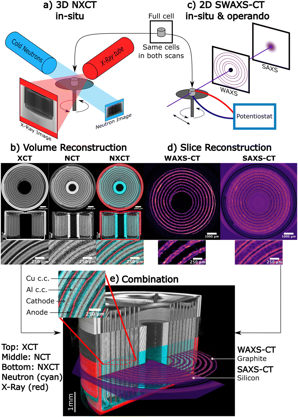 | ||
| Fig. 1 Methodology for the multimodal 3D correlative visualization. (a) Schematic of the neutron and X-ray computed tomography (NXCT) set-up for in situ measurement. NCT and XCT scans were done sequentially. (b) Slices through the reconstructed tomography volumes of the cell. The left part shows XCT data, the middle part shows the NCT data in the identical position and the right part shows the combined NXCT images in false color, with the red component corresponding to X-ray attenuation and the cyan component corresponding to neutron attenuation. Top row: Horizontal slices through the 3D volume. Middle row: vertical slices providing a complementary side view of the internal structure and casing. Bottom rows: Detailed view of the rolled electrode structure. (c) Schematic of the small angle and wide angle scattering computed tomography (SWAXS-CT) measurement setup. (d) Reconstructed 2D SWAXS-CT slices. Left part: Integrated graphite intensity between q = 1.82–1.92 Å−1. Right part: Integrated SAXS intensity between q = 0.025–0.1 Å−1. Bottom: Detailed view showing the anode layers as purple-enhanced regions. (e) Multimodal correlative data and 3D rendering of the cell. Top part: X-ray CT data. Middle part: neutron CT data. Bottom part: Combined NXCT data in false color. A 2D SWAXS CT slice is also shown in the measured position. Right: Integrated graphite intensity. Left: Integrated SAXS intensity. The insert highlights the various components and internal cell damage as observed with NXCT. | ||
Complementary 2D small/wide angle X-ray scattering computed tomography (SWAXS-CT, Fig. 1c) using a focused pencil beam is performed on selected cross-sectional slices in the very same cells. The direct comparison of the former attenuation data, e.g. via color level mappings, with the latter spatially-resolved scattering data (Fig. 1d), e.g. containing pixel-localized individual SWAXS patterns, is advantageous to connect the observed concentration-dependent density variations to crystalline and nanostructured phases in various components. WAXS is sensitive to the change of crystallographic parameters (e.g. graphite and NMC) during (de)lithiation, while SAXS is sensitive to the change of lithiation state of the amorphous nanosized silicon domains.37 Therefore, by selecting a given Bragg peak in the WAXS patterns, a 2D distribution of the associated phase can be obtained in the cell for the selected cross section (for instance, the graphite phase is shown in Fig. 1d, left slice), while integrating SAXS intensity provides a 2D-map of silicon localization and state (Fig. 1d, right slice). More details on the data acquisition, processing and interpretation are available in the Notes S1–S21 (ESI†). The X-rays/neutron correlated view of the aged cell is shown in Fig. 1e. As expected from industry-grade manufacturing, the vast majority of the electrode structure seems rather homogeneous, especially in the 3D attenuation data. There are however some rather distinct inhomogeneities distributed inside the silicon–graphite anode component, visible in all modalities – for instance, some brighter spots are present in the SWAXS 2D integrated intensity maps, while lithium-rich and lithium-poor zones coexist in the NXCT data. These spots and variations are signatures of local structural and/or compositional heterogeneities at the material scale. Moreover, a few macroscale defective regions are evidenced, as seen on the insert in Fig. 1e, showing a zone where the current collector is bent and heavily deformed.
Localizing and exploring cell damage
Spatially resolved measurements in the fully charged and discharged states allow us to better track the local changes during the aging and to gain further understanding of the influence of the rolled cell geometry. Fig. 2 shows the results for the virtually unrolled aged cell after 700 cycles. The fresh cell is shown in Fig. S22 (ESI†). Due to size limitations, only cutouts of the electrode assemblies are depicted with the full-sized images shown in Fig. S24–S31 (ESI†) and the electrochemical data in Fig. S43 and S44 (ESI†).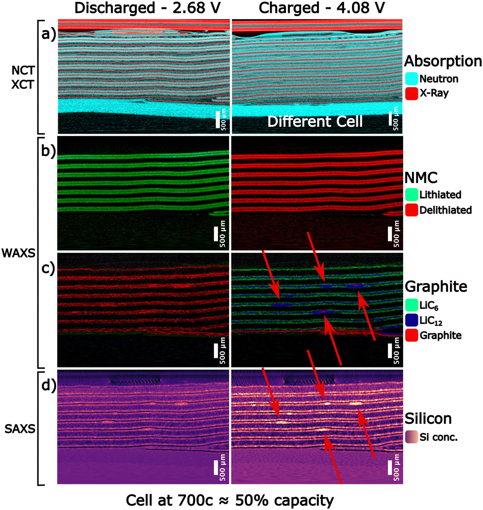 | ||
| Fig. 2 Localization of macroscale deformations and heterogeneities in an aged cell after 700 cycles. SoC: discharged (left) and charged (right). The virtually unrolled tomography slices show the same position in the cell but obtained from the different imaging modalities. (a) Color composite image showing the correlated NXCT tomography, which is sensitive to the lithium distribution due to the neutron attenuation contrast. Note that the charged state shows a slice taken from a different cell than the other images. (b) Color composite image showing the distribution of lithiated NMC (green) and delithiated NMC (red). (c) Color composite image showing the distribution of LiC6 (green), LiC12 (blue) and graphite with poorly lithiated phases (LixC6 with x < 0.2, red). (d) SAXS intensity integrated from q = 0.025–0.1 Å−1, which correlates with the concentration and degree of lithiation of the nanostructured silicon phase. | ||
The unrolled cell representation at 700 cycles reveals several typical features. In the discharged state, the NMC is fully lithiated (green colored), while the graphite in the anode is fully delithiated (red colored), with no obvious inhomogeneities to be observed at this scale. This reverses in the charged state, as expected, where the NMC cathode delithiates homogeneously. This analysis does not explicitly rule out ageing effects in the NMC material, as fatigued phases40 could be present and cause local heterogeneities at a smaller scale. For the anode, however, pronounced inhomogeneities in the lithiation states of graphite can be observed. We observe fully lithiated (LiC6) and partially lithiated states (LiC12) distributed in most parts of the aged cell. Comparing this with the fresh cell in Fig. S22 (ESI†), the loss of lithium inventory becomes clear, as in the fresh cell mostly LiC6 can be observed, while the aged cell shows LiC12 being present in almost all parts of the cell. Therefore, the composite anodes do not reach their fully lithiated state everywhere as a consequence of aging.
Moreover, some large defective zones exhibit even lower lithiation states, as indicated by arrows in Fig. 2. In the very same regions, we also observe SAXS intensity bright spots (Fig. 2d) indicating different behaviors of silicon, as well as massive deformations of the copper current collector. Extended unlithiated/poorly lithiated (LixC6 with x < 0.2, red) and/or partially lithiated (LiC12, blue) graphite zones (Fig. 2c) are only observed in these deformed areas. Zones like this are also present in the fresh cell, but to a lesser extent (Fig. S22, ESI†).
The abnormal behavior in these areas is also confirmed by the correlated NXCT data in Fig. 2a, where the cyan component representing neutron attenuation depicts the movement of lithium. There is an overall intensity change corresponding to the charge and discharge of the anode and cathode respectively, as well as clear heterogeneities of the anode charge state. Voids and lithium-rich zones are found throughout the graphite–silicon layers, on both sides of the current collector, and are spread over the whole cell. Details of the local distribution of lithium are shown in Fig. S23 (ESI†), where a zoom into a small section is pictured. This indicates that the most prominent degradations inside the cells happen in the composite anode, where long-term cycling induces lithium loss and lithium trapping. These phenomena probably correlate to well-known processes in silicon domains36,38,41 due to repeated volume changes and continuous SEI growth during cycling, while the NMC cathode is, as expected, less degraded. This agrees with observations of Visti Graae et al.,34 who have shown that capacity fade in silicon–graphite based cells is predominately caused by lithium inventory loss to silicon, while NMC continues to function normally.
Globally, from Fig. 2, it is evident that besides the general heterogeneities present throughout the entire cell caused by expected ageing effects of the anode, strongly pronounced inhomogeneities in lithium concentration, graphite lithiation, and silicon lithiation occur in the same regions as the deformed copper current collector. Consequently, these features are likely coupled and arise from the same aging mechanism. However, the deformed seed spots observed in Fig. 2 are not the result of cumulative aging processes, as they appear after the formation cycle and are found in all states of charge and aging investigated. Moreover, reference cells without the addition of the electrolyte, and therefore no (electro)chemical activation, do not exhibit these deformations, see Fig. S9 (ESI†). Hence, the deformations are not a consequence of mechanical deformation during cell manufacturing but are rather caused by the electrochemical processes.
Origin and characteristics of macroscale deformations
We use high-resolution synchrotron XCT to further zoom onto one of the large defects (Fig. 3a), directly revealing the pronounced internal damage in this area, while most of the remaining anode appears homogenous down to the particle scale. Particularly, it can be seen that the anode microstructure is dramatically altered around the bent collector. The anode material is compacted, suggesting that the porous microstructure of the anode has collapsed on both sides of the deformed copper foil.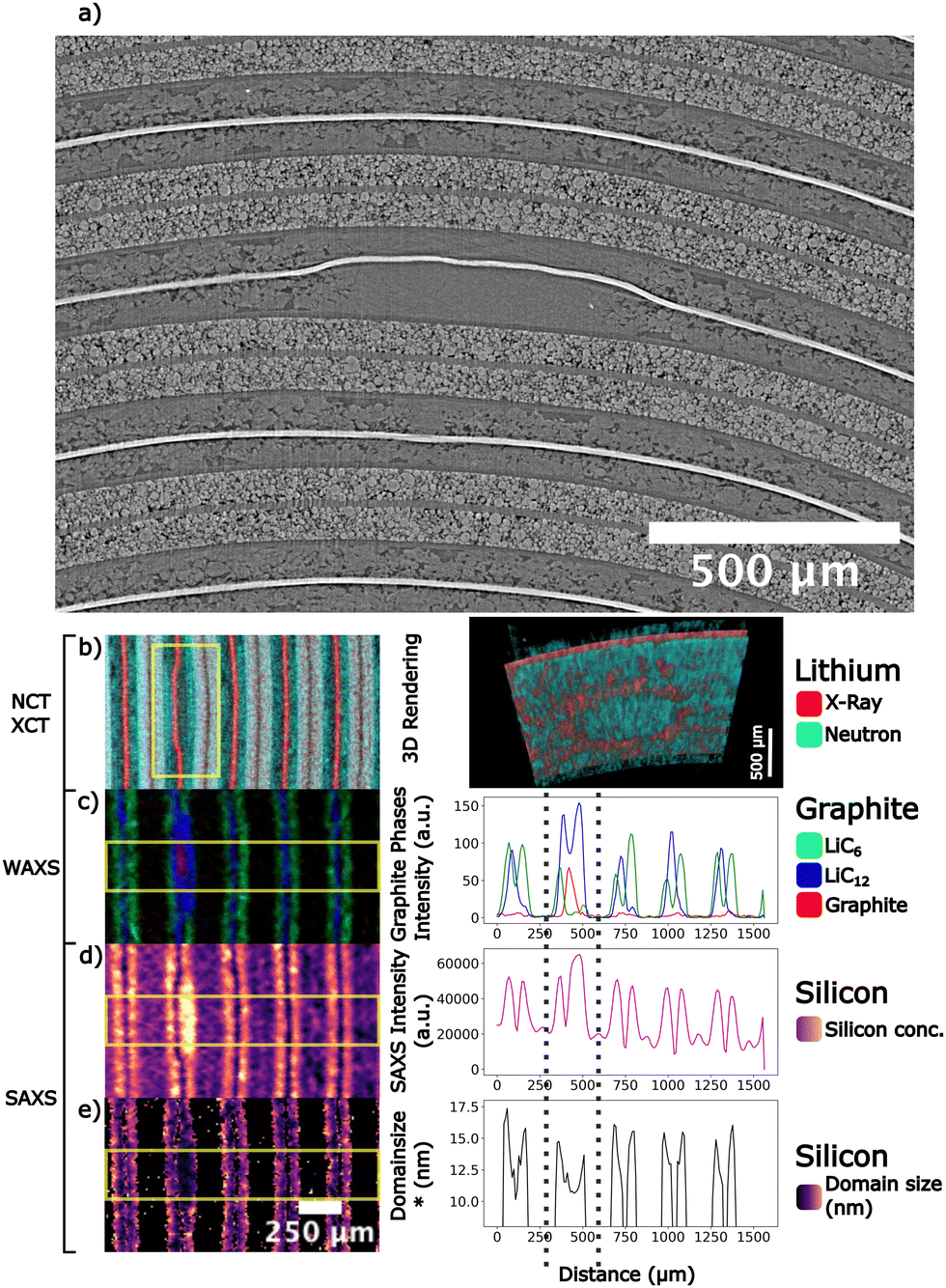 | ||
| Fig. 3 Internal characteristics of a macro-scale defect in the aged cell. (a) High resolution synchrotron tomography slice of a heavily deformed area with (b)–(e) cutouts of the unrolled slices measured with the different modalities (left) and associated image profiles (right). (b) Correlated NXCT tomography (left) and (right) a 3D rendering of this area in the discharged state showing a bend viewed from below, treated with thresholding to highlight the current collector (red) and highly lithiated anode (cyan). (c) Composite image showing the distribution of LiC6 (green), LiC12 (blue) and graphite plus poorly lithiated phases (red). (d) Integrated SAXS intensity, which correlates with concentrations of the nanostructured Si-domains. (e) Calculated d*, a characteristic value to describe the size distribution of the nanostructured Si-domains.37 250 μm scale bar for (b)–(e). | ||
To access more information on the nature and characteristics of this defect, we perform radial profiling of the multimodal data across the very same zone. Fig. 3b–e show zoomed views onto the unrolled bent area pictured in panel (a). The deformed area is pronounced in the images as well as in the profiles. The correlation of the effects becomes well observable: In the raw NXCT data (Fig. 3 panel (b)) the deformed current collector is starkly pronounced, with a lithium accumulation visible close to the interface to the separator. Rendering this part in 3D reveals an elliptical shape to this lithium accumulation inside the defective zone. Moreover, the region seems partially disconnected from the rest of the anode. The information gained from the WAXS-CT (Fig. 3 panel (c)) shows that this area is not charging correctly. Here, only the LiC12 charge state was reached, with the center of the deformation being LixC6 with x < 0.2. The almost non-lithiated central part of the defect lies in the most expanded damaged area, in the inner anode layer and in contact with the collector.
Additional information on the heart of this area arises from the SAXS-CT data analysis, that reveal both intensity and shape variations correlated to heterogeneities in the silicon phase. In Fig. 4, we summarize the principle of the correlation between SAXS features and silicon phase nanostructure. The detailed concept of our qualitative SAXS analysis is given in the methods and ESI,† and representative SAXS datasets are shown and described in detail in Fig. S46–S50 (ESI†). Fig. 4a shows a schematic of the nanoscale organization of amorphous Si domains embedding crystalline FeSi2 particles,38 together with archetypal SAXS intensity profiles obtained in regular regions on Fig. 4b (formed and aged cells, both in charge and discharged states). Usually, characteristic sizes or distances in a two-phase system are detected through the shape and features of the SAXS profile. Here we observe noticeable variations in the mid-q region that corresponds to domain sizes, d = 2π/q, in the range of 6 to 25 nm (blue circle in Fig. 4). These changes develop when silicon expands on charging.37 A practical, model-free measure of the characteristic silicon domain extension can be obtained by extracting the d* value that corresponds to 2π/q*, where q* represents the departure from the high-Q Porod's behavior (see methods and ESI† for further details). The distribution of d* across the cell is indicative of the level of heterogeneities in swelling of silicon, which is related to the lithiation degree. Typically, in regular regions of the formed cell in discharged state, the SAXS is an unfeatured decaying intensity (Fig. 4b, left, red curve) that evolves to the mid q-shaped signal (blue curve) on charging, with an averaged d* of 11.8 nm. In the aged cell the discharged state is already characterized by a d* due to ageing effects, resulting from the incomplete contraction of the silicon phase, and remaining irreversible degree of swelling after long-term cycling (e.g. in this example d* = 12.8 nm). Charging this particular region (i.e. specific voxel of this dataset) results in a subsequent increase up to 14.1 nm for the example shown in Fig. 4b. The d* metric is therefore interesting to compare “regular” and “bent” regions of the battery. As seen in Fig. 3e, the d* varies in the range 10–15 nm, with disrupted behavior coinciding with the damaged area. More precisely, the area associated with the bend shows a smaller mean size of the silicon nanodomains, ca. 11 nm, against 13 to 15 nm in other neighboring intra- or inter-layer regions. Hence, in the bent region, silicon reaches a less lithiated state than elsewhere in the cell, on average.37 This observation is consistent with the presence of an almost inactive graphite part, indicating that the deformed area is probably not significantly contributing to cell charging and discharging anymore, causing a local loss in capacity.
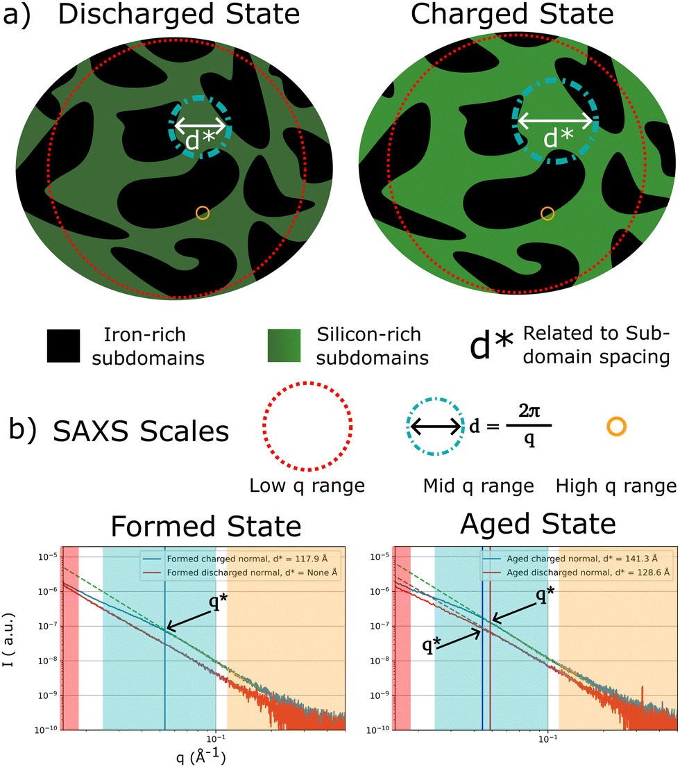 | ||
| Fig. 4 Concept of SAXS-Analysis of nanostructured material. (a) Shows a stylized depiction of the nanostructure of the Si–FeSi2 composite material. (b) Shows two averaged raw SAXS profiles extracted in regular areas for the formed and aged cells respectively, with one curve for the charged state and one curve for the discharged state to highlight the differences in shape caused by the expanding nanostructure. | ||
In addition to the analysis of the SAXS profile shapes through the d* metric, we can also consider the information carried by the total integrated SAXS intensity. In a two-phase system, the intensity I(q) is not only modulated by the form factor of particles (phase A, here silicon) in the surrounding medium (phase B, here FeSi2), but it is also proportional to other terms, namely the volume fraction of phase A and the contrast term that depends on lithium content. As seen in Fig. 3d it is clear that a higher value of the SAXS integrated intensity is observed concomitantly with the reduced expansion (Fig. 3e). The center of the damaged area appears as a bright extended spot in the image. As the volume expansion is low in the very same region, corresponding to a low degree of lithiation and therefore reduced contrast term, the only possibility to account for the extra SAXS intensity is to conclude that there is an abnormally elevated silicon concentration in this area of the cell. Fig. S48 (ESI†) shows more examples of SAXS intensity comparisons in charged and discharged states, in fresh and aged cells, to further evidence the link between local concentration and lithiation degree of silicon. This observation is key because it links the defective area not only to an altered microstructure, limited lithiation ability, and lithium trapping – typical features of microporous anodes aging, but also to a localized defect in composition of the anode.
To conclude, the variations in SAXS features at the micro-scale (Fig. 3d and e) largely deviate from the regular average state, indicating a specific behavior of the Si phase in the bend region, and confirming that the heart of this defective area is mostly inactive. Note that we have analyzed other defects visible from the data and found similar behaviors, with an example of a bent part as observed in the fresh cell shown in Fig. S33 (ESI†).
More information about the lithiation dynamics of these defects was gathered by acquiring the WAXS-CT data during the charging process in an operando experiment. The aged battery was cycled between 2.68 and 4.2 V (Fig. S44, ESI†). We reconstructed the separate slices as described in Methods and highlighted the same area in each snapshot, as shown in Fig. 5. The graphite phases are again depicted in false color, with half of the field of view displayed in the top row and a zoom on the highlighted area in the bottom row. The full images are available in Fig. S34–S42 (ESI†). We can clearly follow the dynamics of the staging process in graphite, starting from delithiated graphite (red) and progressing towards the partially and fully lithiated states, LiC12 (blue) and LiC6 (green), respectively. From the zoomed images, it can be seen that in the deformed area, the lithium diffusion is blocked on the direct interface between the cathode and anode, as there is no lithiation front visible in the form of a gradual change from red to blue/green in this area. Instead, the lithiation of the deformed region is coming from the neighboring anode areas and only starts once these have been mostly lithiated, resulting in an elliptically shaped area of barely lithiated graphite that slowly shrinks during the charge. Even when most of the cell is already fully charged, these areas still exhibit mostly unlithiated graphite at the center. This is consistent with the high-resolution X-ray computed tomography measurements of the deformed area, where no remaining porosity is visible. The tortuosity of these areas is heavily increased, leading to massively extended diffusion paths, poor electrolyte wetting, and, consequently, impeding electrochemical reactions to take place in the inner part of the damaged zone.
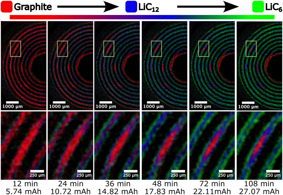 | ||
| Fig. 5 Dynamics of graphite lithiation in large defective zones by operando WAXS-CT. LiC6 is depicted as green, LiC12 as blue, and poorly-lithiated graphite (LixC6 with x < 0.2) as red. Top row: An overview of the aged cell. Bottom row: Zoom on the selected bent area. An elliptically shaped area of graphite can be observed, which slowly shrinks during the charge, lagging behind the rest of the cell. | ||
Correlating defect size and local performance
The massive, deformed areas in Fig. 3 and 5 correspond to high silicon concentration regions, easily localized on the 2D-SAXS integrated intensity maps as bright excess intensity spots. Interestingly, there are also numerous additional bright spots that are smaller in size, and generally do not face any bent current collector (Fig. 6). These smaller clusters of silicon also represent accumulations of the silicon material in the anode, which are a known consequence of agglomeration occurring during the electrode fabrication process.42 This is especially pronounced in the present material, probably because of the complex composite nature of the silicon phase that incorporates crystalline FeSi2 buffering particles. We find that small clusters and large bent areas are very similar regarding their initial silicon concentration and their long-term lithiation state and behavior. Indeed, the shapes and intensity levels of the SAXS profiles (Fig. S48–S50, ESI†) in both fresh and aged cells compare well between the archetypical agglomerate and the one measured in an archetypical bent zone. Nevertheless, at all SoC and SoH they significantly exceed the intensities measured in regular averaged silicon zones in the rest of the cell, confirming that bent areas and agglomerates contain a material much more loaded in silicon. Moreover, the formation cycle seems to have an irreversible impact on this excess silicon, as both agglomerate and bent regions do not recover a fully delithiated state after only one charge/discharge cycle. This is seen from the SAXS profiles in the discharged state that maintain a shaped curvature, typical of expanded nanoscale domains, while regular delithiated silicon data follow a typical q−α decaying intensity law. After aging, we also see that the two types of extra silicon-rich regions are almost not breathing (within fitting errors) during lithiation/delithiation, indicating that they barely work. Irreversible morphological changes are common to any silicon material, especially in the long-term, due to sequences of expansion/contraction and continuous SEI building. The mean size of silicon nanodomains, denoted as d*, was reported in the present amorphous–Si/FeSi2 composite material to extend from 9 to 12 nm in the first cycle on charging, irreversibly reducing to 10 nm on discharging, with little changes in these magnitudes after 300 cycles.37 Typical values of spatially-resolved d* inside the cylindrical cells are summarized in Table S1 (ESI†) and fall in the same range. Globally, d* is an interesting metric to quantify the restrained behavior of bent/agglomerate regions: it plateaus to 10 to 11 nm, while full lithiation induces larger swellings, ca. 15 nm, in regular zones across the cylindrical cells. Consequently, the excess zones are regions where silicon is almost unable to provide capacity to the system and remains stuck in a poorly active state, a phenomenon observed since the formation cycle. Hence, in these regions, SEI formation and initial nanoscale swelling are massive and irreversibly degrade the anode from the very first discharge.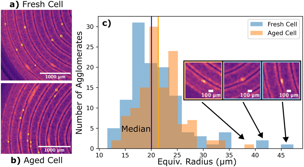 | ||
| Fig. 6 Size and shape of small silicon agglomerates defects. Visualization of small agglomerates in fresh (a) and (b) aged cells using the SAXS-CT integrated intensities. Agglomerates appear as bright spots of excess SAXS intensity and are marked by orange circles. (c) Histogram of the agglomerate size distribution, with inserts showing the largest agglomerates locations and shapes. | ||
The agglomerates were manually segmented in the SAXS-CT data, and their size distribution was analyzed, see Fig. 6. The median radius is 20 microns for the freshly formed cell, a value shifted by 1 μm in the aged cell, in agreement with local material-scale studies reporting silicon re-agglomeration after long-term cycling. Interestingly, a cutoff in the size distribution is observed as well, above which only a few large agglomerates are present. A selection of these is highlighted in the inset of the plot, where one agglomerate seems to slightly distort the current collector. This implies that the agglomerates larger than ca. 50 microns present in the anode slurry and coated onto the copper current collector were responsible for the mechanical deformations observed inside the cell. Additionally, cells that were closed without the addition of an electrolyte do not exhibit any current collector deformations. This shows that the presence of agglomerates during the coating and subsequent calendering steps do not cause the deformed areas, ruling out mechanical deformation during manufacturing. The damage therefore must have happened during the formation cycle since the deformed areas can already be observed inside the fresh cell, which has not been aged. The agglomerates are therefore not causing any physical damage until the first electrochemical cycle. There is, consequently, a critical threshold value above which silicon-rich agglomerates defects cause permanent cell deformations and result in large capacity loss before the cell ever goes into operation (Fig. 7). However, if the agglomerate is small enough the anode microstructure is not irreversibly compressed and lithium ions can still partially reach the graphite phase, enabling it to (de)lithiate during charging and discharging.
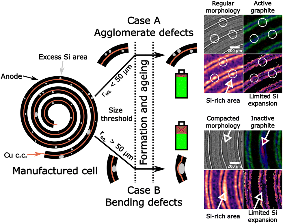 | ||
| Fig. 7 Classification of defects by their impact on local lithiation states and cell integrity. Schematic cross-section (not to scale) of the cell showing the double-sided coated anode (black) and the copper current collector (brown), with regions of excess silicon concentration presented as grey spots. After the formation and aging of the battery, different types of defects are created depending on the size of the excess silicon patches: case A (agglomerates below 50 μm, top) and case B (above 50 μm, bottom). Case A corresponds to a mild alteration of the battery function with reduced silicon activity in the agglomerated zones, while case B leads to macroscale current collector bends and extended damaged anode regions. The latter is prone to compromise the anode integrity and performance. Scale bar for all images 200 μm. | ||
With these results, we address the paramount importance of the composite anode manufacturing process and its direct consequence on cell performance. Homogenization of the slurry holds the key to controlling the number and size of silicon-agglomerated patches dispersed randomly within the rolled geometry of the cell. Large, deformed areas can be considered as pre-weakened regions that may compromise cyclability and lifetime. We may note that these defects account for less than 10% of the volume of the active material in the anode and therefore cannot be responsible for the 50% capacity fade after 700 cycles, which is mostly caused by known degradation mechanisms in silicon-based materials, e.g. SEI formation, particle pulverization, disconnection, Li-trapping, etc. Nevertheless, avoiding localized defects caused by silicon accumulation in the early stages of cell conception and production would reduce failure risks already encoded in the components if they are not checked appropriately. These problems become especially apparent in cylindrical rolled cell geometries with their restricted space conditions but may also affect other geometries providing high energy densities. Correlations between material heterogeneities and deformations have also been observed in cathode materials by Zan et al.,12 further emphasizing the detrimental effects of pre-existing defective areas on the long-term cell stability and safety.
The sizes, shapes, and impact of the cell-level defects might depend on several parameters specific to a chosen material and electrode manufacturing process. Nevertheless, the observations we report here are likely to hold for a range of materials, more particularly complex composite electrodes manufactured employing the usual wet process, as this technique is known to induce materials agglomeration and microstructural defects due to slurry processing and solvent drying steps.43 The herein observed macroscale deformations and defects should be accounted for to optimize electrode manufacturing processes and predict cell lifetime using validated data-driven models.44 For instance, as pre-ageing is activated by the formation cycles, the cell formation protocols must be optimized beyond usual trial-and-error practices.45
We can expect that localized abnormal function not only reduces the overall cell performance but weakens its integrity and endangers its prolonged use. Therefore, establishing the causal link between slurry properties and cell function is an asset to ensure better quality control in the battery manufacturing value chain, as other processing steps like calendaring are also strongly affected.46 This link requires a complex methodology to map key properties such as element, phase, and component distributions concomitantly. Cross-correlation and spatial alignment of atomic-scale information to nano-, micro- and macro-scales characteristics allows one to realize the full integration of knowledge across distinct phases and components, even in a real commercial-grade battery cell cycled and controlled according to realistic industry-grade criteria. The standardization of such advanced multimodal correlative characterization opens the route to qualify many types of cell chemistries and formats in a diversity of charge and health states.
Conclusions
Multiple tomography techniques were applied to industry grade silicon-based lithium-ion battery cells at different states of charge and states of health, which were aligned and correlated to gain multidimensional information on the components and elements inside the working cells. There, macroscopic deformations of the wound structure of the copper current collector were discovered, which already exist in fresh cells that only went through the initial formation cycle. These deformed areas exhibit close to no remaining microporosity and are not charging normally, with the diffusion paths of lithium being significantly disturbed. Further investigations reveal accumulations of silicon in these zones, with lithium accumulations close to the separator-anode interface also being present.Due to these observations, one may draw the conclusion that these defective zones were caused by agglomerates of silicon material that were introduced during the electrode production. Upon the first lithiation, the largest agglomerates expand heavily, which leads to indentations of the current collector, wasting capacity before the cell ever went into use. However, below a certain agglomerate size threshold, in the case of this material around 50 μm equivalent diameter, the anode keeps its integrity and does not cause mechanical cell damage. In this study the raw material that turns unusable from this effect is less than 10% of the total capacity. However, for future high-capacity anode materials including high amounts of silicon this can be expected to cause more significant problems. It is therefore advisable to put special attention towards preventing large agglomerates in the anode slurry before coating to prevent this type of internal damage, which results in wasted capacity, resources, and is potentially responsible for a share of cell failures during the formation cycle.
Experimental procedures
Materials and cell components
The negative electrode used in the coin cells is composed of 25% L20772 powder (20% graphite, 25% a-Si, 55% c-FeSi2), 65% graphite (BTR918), 3% carbon black (super C65) as a conductive agent and 7% LiPAA as a binder, coated with an areal capacity of 2.9 mA h cm−2. In this composite anode the silicon is present as nanosized domains buffered by almost inactive crystalline FeSi2 particles. The cathode is based on 622 nickel–manganese–cobalt oxide (NMC), coated to 2.6 mA h cm−2. The negative electrode therefore has ∼10% excess capacity, which corresponds to usual cell balancing with an increased anode loading to ensure safety. The electrolyte is composed of FEC/EMC 3![[thin space (1/6-em)]](https://www.rsc.org/images/entities/char_2009.gif) :7 (v:v), 1M LiPF6 + 2 wt% VC with a polyolefin based separator.
:7 (v:v), 1M LiPF6 + 2 wt% VC with a polyolefin based separator.
Cell characteristics
The cells are manufactured according to industry standards to keep the industrial relevance, as cells of this format are in active commercial use, e.g. CoinPower CP1054 cells. Applications for these cells include small electronic devices like medical sensors, headphones, and smart devices. However, the size was reduced with respect to CP1054 cells for a better compatibility with the experimental requirements. Particularly the diameter of 8 mm was chosen to ensure sufficient transmission (>10%) for neutron tomography. This miniaturized cylindrical format is well suited to obtain neutron transmissivity in the optimal range for all measurement angles. In fact, other designs based on electrode sheets with large surface area such as pouch cells and prismatic cells contain flat layers, which have extremely low or extremely high neutron/X-ray transmission depending on the measured angle, potentially leading to mediocre reconstruction results.39The cylindrical geometry itself resembles the geometry of 18650 cells with the shared spiral construction. However, due to the nature of small prototype series, the cells were wound by hand instead of using automatized machines. This results a less packed cell, with some additional space above and below the jelly roll. Nevertheless, the cell represents high quality manufacturing and can be used to investigate the behaviors of cylindrical cells.
Electrochemical cycling
The cell formation program applied at VARTA is a standard industrial-grade procedure used for silicon-based batteries, implying several formation cycles at moderate C-rates in the usual potential range of up to 4 V. The cycling program used to age the cell was 2C charge until 4 V, 1C charge until 4.1 V, 0.5C charge until 4.2 V, followed by 2C discharge until 2.8 V. This protocol is applied to age the cells quickly. It lowers the C-rates at high voltages instead of keeping a constant (high) C-rate followed by a CV step. This accelerated program could be less aggressive in terms of degradation of the electrolyte, as it spends less time in unfavorable conditions at 4.2 V. The program was stopped after 700 cycles and the cells were delivered for analysis at SoC 30%.Neutron/X-ray CT (NXCT)
The high-resolution neutron tomography scans were carried out at the NeXT instrument47 of the Institut Laue-Langevin (ILL, Grenoble, France), using a polychromatic cold neutron beam collimated by a 15 mm pinhole over a distance of 10 m. The projections were recorded using a 3 μm thick 157Gd enriched scintillator screen, using a 1.5 times optical magnification onto a scientific CMOS camera sensor for a voxel size of 4.2 μm and a FOV of 8.6 by 8.6 mm. The X-ray computed tomography (XCT) scans were also carried out at the NeXT instrument, using a polychromatic microfocus X-ray source (Hamatsu L12161-07) with 140 kV acceleration voltage and a tungsten target. Details on the data processing and reconstruction are available in the ESI.†Synchrotron X-ray CT (XCT)
High resolution X-ray tomography scans were measured at BM05 of the European Synchrotron Radiation Facility (ESRF, Grenoble, France) using a filtered white beam with 110 keV average energy and a voxel size of 726 nm. Detection was performed with an Optique Peter TwinMic optic with a 10× Mitutoyo long-working-distance objective and a 23 μm lutetium oxyorthosilicate scintillator coupled to a PCO Edge 4.2 CLHS camera. Details on the data processing and reconstruction are available in the ESI.†The cells were contained in PFA tubing between two aluminum plungers to prevent contamination of the beamline in case of catastrophic cell failure induced by accumulated beam damage. The electrical connection was ensured by inserting a small spring between the top plunger and the cell.
Small and wide-angle X-ray computed tomography (SWAXS-CT)
SWAXS-CT measurements were performed at the ID31 beamline of the European Synchrotron Radiation Facility (ESRF, Grenoble, France) using a monochromatic 77 keV X-ray beam, focused to a spot size of ∼5 × 20 μm (vertical × horizontal). 2D diffraction/scattering patterns were acquired with a Pilatus3 X CdTe 2M detector mounted on a suspended rail, which allowed it to be moved automatically from the WAXS position to the SAXS position. The distance of the detector to the sample was roughly 15 cm in the WAXS setup, which allowed a q-range up to ∼10 Å−1 to be measured. A 6-meter flytube under vacuum was inserted in the beam path after the sample to reduce the scattering from the air between the cell and detector in the SAXS position, which was roughly 7.5 meters in total.The same sample holder as with the synchrotron X-ray CT scans was reused for these measurements. This assembly was mounted on a rotatable hexapod sample stage, which in turn was mounted on top of a translation stage.
The SWAXS-CT scans were performed with a series of line scans with 12 ms exposure time, followed by a rotation step. In each line, 1024 translation steps were made for the high-resolution scans and a reduced step count of 512 in the operando data. To minimize risks of data loss, an interlaced approach was used, where three separate subsets with 100 projections between 0–180° were measured, each using the same angular step size, but an offset starting angle. The operando scans acquired 50 angles per interlace step instead.
The cells were charged/discharged in the aligned position at the beamline using a BioLogic SP-50 potentiostat with a current rate of 1C, followed by a constant-voltage step until the current stabilized and finished by letting the cell relax until the voltage stabilized. The raw data is plotted in Fig. S43 and S44 (ESI†).
The 2D diffraction/scattering data was calibrated using a CeO2 standard for WAXS and a Silver Behenate standard for SAXS and azimuthally integrated using pyFAI48 and scripts developed inhouse. The reconstruction was done using the SART algorithm implemented in astra-toolbox.49,50
Table 1 shows the used integration range to evaluate the WAXS-CT data, with the corresponding lithiation grades in graphite taken from Tardif et al.51 Regarding NMC, we chose the 113 and 110 Bragg reflections to identify the state of lithiation, as depicted in Fig. S45 (ESI†). By integrating the corresponding peak in the selected regions we are able to label the NMC as delithiated or lithiated without the need for refinement. Note that lattice parameter variations could exist as a consequence of fatigued NMC phases, but their observation would require high resolution diffractograms and corresponding refinement methods, which is outside of the scope of this study.
| Component | q (Å−1) | x in LixC6 |
|---|---|---|
| Lithiated NMC622 | 4.57–4.62 | — |
| Delithiated NMC622 | 4.45–4.50 | — |
| LiC6 | 1.67–1.73 | 1 |
| LiC12 | 1.78–1.82 | 0.2–0.5 |
| (Poorly lithiated) graphite LixC6 with x < 0.2 and graphite | 1.82–1.90 | 0–0.2 |
Multimodal datasets alignments
By measuring the same cell with multiple techniques, complementary datasets were obtained. However, these datasets need to be aligned as it is nearly impossible to mount the cells in the exact same orientation multiple times on different instruments. To achieve this, specialized registration algorithms are necessary, namely a modified digital volume correlation algorithm known as multimodal registration,52 which is implemented in the open-source software package Spam.53 This technique produces transformation tensors that describe the transformation required to align the volumes.This algorithm requires two volumes of identical size. To achieve this, the XCT scans measured on NeXT were scaled up from 1024 × 1024 to 2048 × 2048 pixels using Fiji54 with linear interpolation. The XCT/NCT scans are first pre-aligned by eye in the interactive eye registration tool included in spam, and then aligned fully using the modified digital volume correlation algorithm for multimodal registration. The transformed volumes are then combined into a single dataset by encoding the different modalities as color channels in a RGB image. This combination is always depicted with the red color component of the image representing X-ray attenuation and cyan color component representing neutron attenuation. This combined view helps differentiating between the components and allows for simple segmentation of the components by setting appropriate threshold values.
The position of the SWAXS-CT scans inside the cells was determined by matching the positions and size of deformations observed in the XCT data taken on NeXT with the attenuation data obtained in the SAXS-CT measurements roughly by eye, and then applying the DVC algorithm to obtain exact rotations and translations. The deformed attenuation slice was then compared against every slice in the cell to obtain the correct height from the minimal difference between the two images.
Virtual unrolling of the cell
With the circular geometry being impractical for many analyses, a virtual unrolling script was applied to straighten the electrode assemblies. The implementation is based on the scripts available in the software package openCV.55 The script to unroll the cells first identifies the center and radius of the cell using the Hough transformation function to detect the outside casing and then applies a polar transformation based on these parameters. Conveniently, some component of the cell housing produces a diffraction maximum showing two clean circles when integrated in the WAXS-CT analysis (S21), which was used to determine the parameters for the virtual unrolling.SAXS analysis and silicon nanodomain characteristics
The SAXS 1D profiles show a decaying intensity as a function of the momentum transfer q, which is changing depending on the lithiation degree of silicon, both in intensity and shape. It is difficult to quantitatively model this data as they are quite unshaped due to the hierarchy of scales and large polydispersity present in the anode material. In a previous work,37 we evaluated the growing/shrinking of silicon nanodomains during lithium uptake/release by introducing SAXS intensity integration methods enabling global intensity variations monitoring, together with a simple, model-independent metric, determined as d* = 2π/q*, where q* is a typical value where an inflexion appears in the I(q) profiles. We adapted this method to the SAXS-CT data analysis (more details are given in the ESI†). The d* value for each SAXS pattern was determined using a departure from q−x method. The raw SAXS data (with a random example shown in Fig. S46, ESI†) was pre-treated by removing all points with an intensity lower than 10−9 a.u. and then selecting the longest remaining continuous segment at high q for the analysis. A q−x function was then fitted into the datapoints in the high-q region, skipping the starting 30% and skipping the last 20% to avoid fitting into the expected feature as well as noisy areas. The q value where the data deviates more than 3% from the fit was set as the q* value. This point in q was then transformed into real space and saved as d*. An exemplary evaluation is depicted in Fig. S47 (ESI†). By running this on all points and saving the departure values in an array, the entire dataset is processed into the d* analysis. To prevent noise and false values all cut lines shorter than 150 entries were discarded. All fits with a slope higher than 4.3 (unphysical) or lower than 2.5 (inconsistent with previous SAXS data in the same material37) were also discarded. Truly delithiated states turn out impossible to fit because the I(q) is practically unshaped in that case, and only decays with a unique slope, such that defining the departure value is either impossible or leads to meaningless values.Data and code availability
The data supporting the findings are available within the main text and ESI.† More detailed data, as well as the code to process the raw data can be made available upon request.Author contributions
SL, LH, RB, JD, and SK conceptualized this project and acquired external funding. EL, SL, LH, and JD developed the correlative multimodal characterization experiments and the large-scale facility workflow. SL, LH, RB and JD supervised the PhD of EL in collaboration with SK and BF. EL, LH and SL performed the NeXT experiments. EL, JD, LH performed the ID31 Experiments with the help of MM, VV, and OK. EL and PC performed the BM05 Experiments. SK and BF were responsible for cell preparation and aging. EL processed, visualized, and analyzed the data, with help of LH, JD, and SL. EL, LH, RB, BF, SK, JD, and SL discussed the results and prepared the manuscript. All authors contributed to review and editing.Conflicts of interest
There are no conflicts to declare.Acknowledgements
We acknowledge financial support from the European Union's Horizon 2020 research and Innovation programs No. 875514 (ECO2LIB) as well as No. 847439 (InnovaXN) under the Marie Skłodowska-Curie grant agreement. The SWAXS-CT synchrotron data has been acquired and analyzed in the frame of MA-4929 (Battery Pilot Hub at ESRF on “Multi-scale Multi-techniques investigations of Li-ion batteries: towards a European Battery Hub”), IH-CH-1604 and IH-CH-1611. Beamtime at BM05 at ESRF has been acquired in IH-CH-1700. Neutron beamtime for this study was provided by the Institut Laue Langevin on NeXT (1-05-13, INTER-467 and -487, LTP-1-4). We thank Kalvin Buckley for technical support, as well as Alessandro Tengattini, Olga Stamati, Thomas Vorauer, Samuel Tardif and Isaac Martens for the fruitful discussions. We also thank the Institut Laue-Langevin and European Synchrotron Radiation Facility for the allocated beamtime and availability of equipment.References
- Z. P. Cano, D. Banham, S. Ye, A. Hintennach, J. Lu, M. Fowler and Z. Chen, Nat. Energy, 2018, 3, 279–289 Search PubMed.
- Y. Ding, Z. P. Cano, A. Yu, J. Lu and Z. Chen, Electrochem. Energy Rev., 2019, 2, 1–28 CrossRef CAS.
- M. Li, J. Lu, Z. Chen and K. Amine, Adv. Mater., 2018, 30, 1800561 CrossRef PubMed.
- J. T. Frith, M. J. Lacey and U. Ulissi, Nat. Commun., 2023, 14, 420 CrossRef CAS PubMed.
- M. Titirici, Adv. Energy Mater., 2021, 11, 2003700 CrossRef CAS.
- G. Harper, R. Sommerville, E. Kendrick, L. Driscoll, P. Slater, R. Stolkin, A. Walton, P. Christensen, O. Heidrich, S. Lambert, A. Abbott, K. Ryder, L. Gaines and P. Anderson, Nature, 2019, 575, 75–86 Search PubMed.
- P. Rozier and J. M. Tarascon, J. Electrochem. Soc., 2015, 162, A2490–A2499 CrossRef CAS.
- L. Zhang, C. Zhu, S. Yu, D. Ge and H. Zhou, J. Energy Chem., 2022, 66, 260–294 Search PubMed.
- Y. Lu, X. Rong, Y.-S. Hu, L. Chen and H. Li, Energy Storage Mater., 2019, 23, 144–153 CrossRef.
- J. Amici, P. Asinari, E. Ayerbe, P. Barboux, P. Bayle-Guillemaud, R. J. Behm, M. Berecibar, E. Berg, A. Bhowmik, S. Bodoardo, I. E. Castelli, I. Cekic-Laskovic, R. Christensen, S. Clark, R. Diehm, R. Dominko, M. Fichtner, A. A. Franco, A. Grimaud, N. Guillet, M. Hahlin, S. Hartmann, V. Heiries, K. Hermansson, A. Heuer, S. Jana, L. Jabbour, J. Kallo, A. Latz, H. Lorrmann, O. M. Løvvik, S. Lyonnard, M. Meeus, E. Paillard, S. Perraud, T. Placke, C. Punckt, O. Raccurt, J. Ruhland, E. Sheridan, H. Stein, J. Tarascon, V. Trapp, T. Vegge, M. Weil, W. Wenzel, M. Winter, A. Wolf and K. Edström, Adv. Energy Mater., 2022, 12, 2102785 Search PubMed.
- T. Vegge, J. Tarascon and K. Edström, Adv. Energy Mater., 2021, 11, 2100362 CrossRef CAS.
- G. Zan, J. Zhang, F. Monaco, S. Gul, G. Qian, J. Li, D. J. Vine, P. Cloetens, W. Yun, P. Pianetta and Y. Liu, J. Mater. Chem. A, 2021, 9, 19886–19893 RSC.
- J. S. Edge, S. O’Kane, R. Prosser, N. D. Kirkaldy, A. N. Patel, A. Hales, A. Ghosh, W. Ai, J. Chen, J. Yang, S. Li, M.-C. Pang, L. Bravo Diaz, A. Tomaszewska, M. W. Marzook, K. N. Radhakrishnan, H. Wang, Y. Patel, B. Wu and G. J. Offer, Phys. Chem. Chem. Phys., 2021, 23, 8200–8221 RSC.
- C. Uhlmann, J. Illig, M. Ender, R. Schuster and E. Ivers-Tiffée, J. Power Sources, 2015, 279, 428–438 CrossRef CAS.
- C. R. Birkl, M. R. Roberts, E. McTurk, P. G. Bruce and D. A. Howey, J. Power Sources, 2017, 341, 373–386 CrossRef CAS.
- A. A. Franco, A. Rucci, D. Brandell, C. Frayret, M. Gaberscek, P. Jankowski and P. Johansson, Chem. Rev., 2019, 119, 4569–4627 CrossRef CAS PubMed.
- R. F. Ziesche, N. Kardjilov, W. Kockelmann, D. J. L. Brett and P. R. Shearing, Joule, 2022, 6, 35–52 CrossRef CAS.
- A. P. Black, A. Sorrentino, F. Fauth, I. Yousef, L. Simonelli, C. Frontera, A. Ponrouch, D. Tonti and M. R. Palacín, Chem. Sci., 2023, 14, 1641–1665 RSC.
- J. Scharf, M. Chouchane, D. P. Finegan, B. Lu, C. Redquest, M. Kim, W. Yao, A. A. Franco, D. Gostovic, Z. Liu, M. Riccio, F. Zelenka, J.-M. Doux and Y. S. Meng, Nat. Nanotechnol., 2022, 17, 446–459 CrossRef CAS PubMed.
- T. Vorauer, P. Kumar, C. L. Berhaut, F. F. Chamasemani, P.-H. Jouneau, D. Aradilla, S. Tardif, S. Pouget, B. Fuchsbichler, L. Helfen, S. Atalay, W. D. Widanage, S. Koller, S. Lyonnard and R. Brunner, Commun. Chem., 2020, 3, 141 CrossRef CAS PubMed.
- D. P. Finegan, M. Scheel, J. B. Robinson, B. Tjaden, M. Di Michiel, G. Hinds, D. J. L. Brett and P. R. Shearing, Phys. Chem. Chem. Phys., 2016, 18, 30912–30919 RSC.
- K. P. C. Yao, J. S. Okasinski, K. Kalaga, I. A. Shkrob and D. P. Abraham, Energy Environ. Sci., 2019, 12, 656–665 RSC.
- D. P. Finegan, A. Quinn, D. S. Wragg, A. M. Colclasure, X. Lu, C. Tan, T. M. M. Heenan, R. Jervis, D. J. L. Brett, S. Das, T. Gao, D. A. Cogswell, M. Z. Bazant, M. Di Michiel, S. Checchia, P. R. Shearing and K. Smith, Energy Environ. Sci., 2020, 13, 2570–2584 RSC.
- S. Tardif, N. Dufour, J.-F. Colin, G. Gébel, M. Burghammer, A. Johannes, S. Lyonnard and M. Chandesris, J. Mater. Chem. A, 2021, 9, 4281–4290 RSC.
- T. M. M. Heenan, I. Mombrini, A. Llewellyn, S. Checchia, C. Tan, M. J. Johnson, A. Jnawali, G. Garbarino, R. Jervis, D. J. L. Brett, M. Di Michiel and P. R. Shearing, Nature, 2023, 617, 507–512 CrossRef CAS PubMed.
- D. Matras, T. E. Ashton, H. Dong, M. Mirolo, I. Martens, J. Drnec, J. A. Darr, P. D. Quinn, S. D. M. Jacques, A. M. Beale and A. Vamvakeros, J. Power Sources, 2022, 539, 231589 CrossRef CAS.
- D. Petz, M. J. Mühlbauer, V. Baran, A. Schökel, V. Kochetov, M. Hofmann, V. Dyadkin, P. Staron, G. Vaughan, U. Lienert, P. Müller-Buschbaum and A. Senyshyn, Energy Storage Mater., 2021, 41, 546–553 CrossRef.
- I. Martens, A. Vamvakeros, N. Martinez, R. Chattot, J. Pusa, M. V. Blanco, E. A. Fisher, T. Asset, S. Escribano, F. Micoud, T. Starr, A. Coelho, V. Honkimäki, D. Bizzotto, D. P. Wilkinson, S. D. M. Jacques, F. Maillard, L. Dubau, S. Lyonnard, A. Morin and J. Drnec, ACS Energy Lett., 2021, 6, 2742–2749 CrossRef CAS.
- C. L. Berhaut, M. Mirolo, D. Z. Dominguez, I. Martens, S. Pouget, N. Herlin-Boime, M. Chandesris, S. Tardif, J. Drnec and S. Lyonnard, Adv Energy Mater., 2023, 13, 2301874 CrossRef CAS.
- D. Atkins, E. Capria, K. Edström, T. Famprikis, A. Grimaud, Q. Jacquet, M. Johnson, A. Matic, P. Norby, H. Reichert, J. Rueff, C. Villevieille, M. Wagemaker and S. Lyonnard, Adv. Energy Mater., 2022, 12, 2102694 CrossRef CAS.
- P. Pietsch, M. Hess, W. Ludwig, J. Eller and V. Wood, Sci. Rep., 2016, 6, 27994 CrossRef CAS PubMed.
- M. Yusuf, J. M. LaManna, P. P. Paul, D. N. Agyeman-Budu, C. Cao, A. R. Dunlop, A. N. Jansen, B. J. Polzin, S. E. Trask, T. R. Tanim, E. J. Dufek, V. Thampy, H.-G. Steinrück, M. F. Toney and J. Nelson Weker, Cell Rep. Phys. Sci., 2022, 3, 101145 CrossRef CAS.
- R. F. Ziesche, T. Arlt, D. P. Finegan, T. M. M. Heenan, A. Tengattini, D. Baum, N. Kardjilov, H. Markötter, I. Manke, W. Kockelmann, D. J. L. Brett and P. R. Shearing, Nat. Commun., 2020, 11, 777 CrossRef CAS PubMed.
- K. V. Graae, X. Li, D. R. Sørensen, E. Ayerbe, I. Boyano, D. Sheptyakov, M. R. V. Jørgensen and P. Norby, J. Power Sources, 2023, 570, 232993 CrossRef CAS.
- J. Gelb, D. P. Finegan, D. J. L. Brett and P. R. Shearing, J. Power Sources, 2017, 357, 77–86 CrossRef CAS.
- T. Vorauer, J. Schöggl, S. G. Sanadhya, M. Poluektov, W. D. Widanage, L. Figiel, S. Schädler, B. Tordoff, B. Fuchsbichler, S. Koller and R. Brunner, Commun. Mater., 2023, 4, 44 CrossRef CAS.
- C. L. Berhaut, D. Z. Dominguez, P. Kumar, P.-H. Jouneau, W. Porcher, D. Aradilla, S. Tardif, S. Pouget and S. Lyonnard, ACS Nano, 2019, 13, 11538–11551 CrossRef CAS PubMed.
- P. Kumar, C. L. Berhaut, D. Zapata Dominguez, E. De Vito, S. Tardif, S. Pouget, S. Lyonnard and P. Jouneau, Small, 2020, 16, 1906812 CrossRef CAS PubMed.
- T. M. M. Heenan, C. Tan, A. J. Wade, R. Jervis, D. J. L. Brett and P. R. Shearing, Mater. Des., 2020, 191, 108585 CrossRef CAS.
- A. S. Leach, A. V. Llewellyn, C. Xu, C. Tan, T. M. M. Heenan, A. Dimitrijevic, K. Kleiner, C. P. Grey, D. J. L. Brett, C. C. Tang, P. R. Shearing and R. Jervis, Front. Chem. Eng., 2022, 3, 794194 CrossRef.
- H. Wang, S.-H. Lu, X. Wang, S. Xia and H. Beng Chew, J. Phys. Appl. Phys., 2022, 55, 063001 CrossRef CAS.
- A. du Baret de Limé, T. Lein, S. Maletti, K. Schmal, S. Reuber, C. Heubner and A. Michaelis, Batteries Supercaps, 2022, 5, e202200239 CrossRef.
- W. B. Hawley and J. Li, J. Energy Storage, 2019, 25, 100862 CrossRef.
- P. S. Grant, D. Greenwood, K. Pardikar, R. Smith, T. Entwistle, L. A. Middlemiss, G. Murray, S. A. Cussen, M. J. Lain, M. J. Capener, M. Copley, C. D. Reynolds, S. D. Hare, M. J. H. Simmons, E. Kendrick, S. P. Zankowski, S. Wheeler, P. Zhu, P. R. Slater, Y. S. Zhang, A. R. T. Morrison, W. Dawson, J. Li, P. R. Shearing, D. J. L. Brett, G. Matthews, R. Ge, R. Drummond, E. C. Tredenick, C. Cheng, S. R. Duncan, A. M. Boyce, M. Faraji-Niri, J. Marco, L. A. Roman-Ramirez, C. Harper, P. Blackmore, T. Shelley, A. Mohsseni and D. J. Cumming, J. Phys. Energy, 2022, 4, 042006 CrossRef CAS.
- A. Weng, P. Mohtat, P. M. Attia, V. Sulzer, S. Lee, G. Less and A. Stefanopoulou, Joule, 2021, 5, 2971–2992 CrossRef CAS.
- X. Lu, S. R. Daemi, A. Bertei, M. D. R. Kok, K. B. O’Regan, L. Rasha, J. Park, G. Hinds, E. Kendrick, D. J. L. Brett and P. R. Shearing, Joule, 2020, 4, 2746–2768 CrossRef CAS.
- A. Tengattini, N. Lenoir, E. Andò, B. Giroud, D. Atkins, J. Beaucour and G. Viggiani, Nucl. Instrum. Methods Phys. Res., Sect. A, 2020, 968, 163939 CrossRef CAS.
- J. Kieffer and D. Karkoulis, J. Phys. Conf. Ser., 2013, 425, 202012 CrossRef.
- W. Van Aarle, W. J. Palenstijn, J. De Beenhouwer, T. Altantzis, S. Bals, K. J. Batenburg and J. Sijbers, Ultramicroscopy, 2015, 157, 35–47 CrossRef CAS PubMed.
- W. Van Aarle, W. J. Palenstijn, J. Cant, E. Janssens, F. Bleichrodt, A. Dabravolski, J. De Beenhouwer, K. Joost Batenburg and J. Sijbers, Opt. Express, 2016, 24, 25129 CrossRef PubMed.
- S. Tardif, N. Dufour, J.-F. Colin, G. Gébel, M. Burghammer, A. Johannes, S. Lyonnard and M. Chandesris, J. Mater. Chem. A, 2021, 9, 4281–4290 RSC.
- E. Tudisco, C. Jailin, A. Mendoza, A. Tengattini, E. Andò, S. A. Hall, G. Viggiani, F. Hild and S. Roux, Meas. Sci. Technol., 2017, 28, 095401 CrossRef.
- O. Stamati, E. Andò, E. Roubin, R. Cailletaud, M. Wiebicke, G. Pinzon, C. Couture, R. Hurley, R. Caulk, D. Caillerie, T. Matsushima, P. Bésuelle, F. Bertoni, T. Arnaud, A. Laborin, R. Rorato, Y. Sun, A. Tengattini, O. Okubadejo, J.-B. Colliat, M. Saadatfar, F. Garcia, C. Papazoglou, I. Vego, S. Brisard, J. Dijkstra and G. Birmpilis, J. Open Source Software, 2020, 5, 2286 CrossRef.
- J. Schindelin, I. Arganda-Carreras, E. Frise, V. Kaynig, M. Longair, T. Pietzsch, S. Preibisch, C. Rueden, S. Saalfeld, B. Schmid, J.-Y. Tinevez, D. J. White, V. Hartenstein, K. Eliceiri, P. Tomancak and A. Cardona, Nat. Methods, 2012, 9, 676–682 CrossRef CAS PubMed.
- G. R. Bradski and A. Kaehler, Learning OpenCV: computer vision with the OpenCV library, O’Reilly, Beijing, 1. edn, 2011 Search PubMed.
Footnote |
| † Electronic supplementary information (ESI) available. See DOI: https://doi.org/10.1039/d4ee00590b |
| This journal is © The Royal Society of Chemistry 2024 |