 Open Access Article
Numerical one-dimensional investigations on a multi-cylinder spark ignition engine using hydrogen/ethanol, hydrogen/methanol and gasoline in dual fuel mode
Ufaith
Qadiri
 *
*
Faculty of Engineering, Department of Mechanical Engineering, Sreenidhi Institute of Science and Technology, Ghatkesar, Hyderabad, Telangana, India 501301. E-mail: ufaith.q@sreenidhi.edu.in; ufaith.qadri@gmail.com; Tel: +917006417826
First published on 19th December 2023
Abstract
This study enhances the application of alternative fuels—specifically hydrogen, methanol, and ethanol—in a multi-cylinder gasoline engine. Using the one-dimensional simulation software AVL Boost, the study aims to predict the performance and emission characteristics of two distinct blends: hydrogen (10%) blended with methanol (90%) and hydrogen (10%) blended with ethanol (90%), in comparison to the baseline of 100% gasoline. The multi-cylinder spark ignition engine operates at variable speed under constant load conditions. The analysis of combustion characteristics involves monitoring pressure at different crank angles for all fuels. The anticipated performance parameters include power, torque, brake specific fuel consumption (BSFC), and brake mean effective pressure (BMEP). Notably, among the blended fuels, the hydrogen/ethanol blend exhibited superior efficiency, with a 20% increase in power compared to the hydrogen/methanol blend. The 90% ethanol with 10% hydrogen blend and the 90% methanol with 10% hydrogen blend both showed improved performance and contributed to reduced emissions compared to the 100% gasoline fuel. Favourable results were observed for CO, HC, and NOx emissions. While hydrogen combustion is carbon-free, the addition of ethanol and methanol led to slight carbon-based emissions, with a marginal increase in NOx for the hydrogen/methanol blend compared to the 100% gasoline fuel.
Environmental significanceThe manuscript entitled, Numerical One-dimensional Investigations on a Multi-cylinder Spark Ignition Engine using Hydrogen/Ethanol, Hydrogen/Methanol and Gasoline in Dual Fuel mode. Is an original research paper that has not been published and is not in consideration in any other journal. This is a computational-based work performed on AVL Boost Simulation Software to predict the performance and emission characteristics of an MPFI Engine fueled with various alternative fuels. This work has great significance in Environmental Science. It will help in improving the environmental air quality by reducing emissions from internal combustion engines in vehicles. Increasing pollutants in the atmosphere increase the overall atmospheric temperature, which in turn is responsible for the global warming and disturbance of the ecosystem, creating an imbalance in human growth. Thus, this work will also have a great impact on reducing global warming and mitigating the negative effects of pollution. In summary, this study mostly focuses on reducing the emissions from IC engines, trying to meet the future emission norms, and creating a global atmosphere that is pollution-free. |
Introduction
The current approach to fulfilling our energy requirements, largely dependent on fossil fuels, is increasingly unsustainable. Traditional energy sources, once overlooked, are now clearly finite. Fossil fuel prices have experienced significant fluctuations, initially influenced by economic growth, particularly in Asian nations, and later affected by a global recession.1 Relying on fossil fuels for future energy needs is not a viable long-term solution and entails higher expenditure. Transitioning to alternative energy sources can eliminate or reduce global emissions, fostering a more stable world. While the use of biofuels is a method to decrease greenhouse gas emissions, it comes with adverse effects such as deforestation, pesticide pollution, and carbon storage depletion.2 Fuel cells have been under extensive research, yielding highly promising results. However, they have several drawbacks, including high cost, added bulk, and reduced efficiency at full load. In response to these challenges, a hydrogen-fuelled gasoline alternative is emerging. The prospect of powering vehicles with hydrogen in the near future presents a cost-effective alternative to fuel cell technology. The operational concept of a hydrogen-fuelled gasoline engine mirrors that of a conventional gasoline engine. Consequently, it becomes feasible to develop an engine that can run on both gasoline and hydrogen, a crucial factor for the widespread adoption of hydrogen production. The hydrogen internal combustion engine generates only NOx as the sole harmful pollutant.3 Scientists have shown significant interest in alternative fuels, such as hydrogen, LPG, LNG, biogas, and ethanol. Hydrogen, in particular, stands out as a carbon-free renewable source that generates only water after combustion.4 Integrating hydrogen into gasoline engines serves as a bridge between conventionally powered hydrocarbon vehicles and those using alternative fuels. On a related note, natural gas emerges as the most proximate sustainable alternative energy source to hydrogen owing to its low hydrogen/carbon ratio.5 Hydrogen can be produced through the conversion of fossil fuels or biomass, electrolysis, or direct thermoelectric solar transformation.6 Moreover, since hydrogen gas is produced from alternative energy sources, it is a very clean and eco-friendly fuel, and it may be utilized as a transporter of secondary energy like electric power. Although some investigators have employed hydrogen in homogeneous charged compression ignition engines (HCCI), its widespread use is unlikely in the coming years due to challenges coordinating the beginning of combustion and its limited operational capabilities.7 For a 4-stroke diesel engine, Liew et al.8 investigated the influence of hydrogen enriching on ignition parameters based on the braking engine thrust and hydrogen enrichment amount. The ignition time value was reduced and the highest process of heat generation value was reduced under increasing engine loading and high hydrogen levels. At varied engine loads, Bari and Esmail9 studied the effects of various quantities of a hydrogen/oxygen gas combination produced by an alkaline water electrolyzer as a supplementary fuel in a four-stroke, direct-injection diesel engine. Although the injection of the hydrogen/oxygen combination increased the brake thermal efficiency and emissions (hydro carbon, carbon monoxide, & carbon dioxide), the increase in nitrogen oxides could not be avoided. Miyamoto et al.10 conducted research on a four-stroke common-rail compression ignition engine. The inlet valve was sprayed with hydrogen, and the combustion chamber was filled with diesel fuel. The usage of low-temperature ignition (varying fuel spray time) and EGR NOx emissions were also regulated. Xiao et al. investigated the vehicle emission and performance in a 4-stroke, compression ignition at a constant engine speed with various amount of methane gas.11 When compared to diesel fuel, adding biogas with the same energy content reduced NOx emissions. Aydin et al.12 published the findings on a CI engine (engine capacity 296 cm3 & 5.59 kW) driven by two fuel types (diesel and liquefied petroleum in various ratios). They demonstrated that using LPG infused in the liquid state to the fuel can reduce HC and CO emissions by 20–30%, while increasing NOx emissions by 6%. Various studies have indicated that using edible and non-edible vegetable oil, animal fat, and waste oil as a renewable fuel in diesel engines reduces CO, HC, NOx, smoke, and soot generation. Numerous scientists have used different mixtures of diesel-biodiesel and additives in a diesel engine to conduct experiments. Abdurrahman et al.13 found that using 5% & 20% water plus 3% Triton X-100 stirred at 3000 rpm over 20 minutes gave the best stabilization over 60 days. Abdurrahman et al.13 discovered that when the H2O percentage in the emulsified mixture grows, the vehicle torque, power, and braking efficiency improve, while the CO percentage decreases. According to Dubey et al.,14 the highest Brake thermal efficiency arises when the emulsion contains 30% water. The emulsion has a one-week stability with 10% water and a four-week stability with 30% water. Patil et al.15 discovered that biodiesel with 5% water and 3% surfactant concentration has the best stability. They also found that when the water proportion increased, the emulsion's stability decreased, leading to an increase in the brake thermal efficiency and a drop in nitrogen oxides. This research aims to advance the utilization of LPG, hydrogen, and emulsion fuel in a gasoline direct ignition engine operating in dual fuel mode. While numerous researchers have individually explored emulsion fuel, LPG, and hydrogen in compression ignition engines, there has been no concurrent investigation involving LPG, hydrogen, and water-based emulsion fuel in a gasoline direct injection engine. This study will assess the collective impact of these fuels on the overall performance, emissions, and combustion characteristics in dual fuel mode. The blended fuel, now containing both hydrogen and ethanol, is used as a fuel source in the engine.During combustion, hydrogen has a high flame speed and can enhance the overall combustion process, potentially leading to improved efficiency and reduced emissions. Considerable commendation is due for extensive research to be conducted on diverse alternative fuels, displaying potential reductions in emissions, addressing the global energy demand through decreased reliance on conventional fuels, and increased use of alternative options. This particular study focuses on exploring the effectiveness of hydrogen/ethanol and hydrogen/methanol blends for combustion in spark ignition engines. While much of the existing research has concentrated on hydrogen fuel as a standalone entity, there has been limited work focused on blending two alternative fuels to enhance the engine performance and mitigate carbon-based harmful emissions. Furthermore, the potential future applications of this research involve the integration of the findings into internal combustion engines to enhance performance and minimize detrimental emissions. However, achieving commercial viability requires additional research efforts. One of the primary challenges in this endeavor lies in effectively storing hydrogen fuel, known for its volatility and high flammability, posing potential knocking issues. Nevertheless, this obstacle can be addressed by incorporating blended fuels to stabilize combustion and diminish the tendency for knocking. Table 1 provides a comprehensive overview of the properties of various alternative fuels and conventional gasoline fuel.
| Properties | Hydrogen | Gasoline | Ethanol | Methanol |
|---|---|---|---|---|
| Chemical formula | H2 | C8H18 | C2H6O | CH3OH |
| Stoichiometric air/fuel ratio | 34.3![[thin space (1/6-em)]](https://www.rsc.org/images/entities/char_2009.gif) : :![[thin space (1/6-em)]](https://www.rsc.org/images/entities/char_2009.gif) 1 1 |
14.7![[thin space (1/6-em)]](https://www.rsc.org/images/entities/char_2009.gif) : :![[thin space (1/6-em)]](https://www.rsc.org/images/entities/char_2009.gif) 1 1 |
9![[thin space (1/6-em)]](https://www.rsc.org/images/entities/char_2009.gif) : :![[thin space (1/6-em)]](https://www.rsc.org/images/entities/char_2009.gif) 1 1 |
6![[thin space (1/6-em)]](https://www.rsc.org/images/entities/char_2009.gif) : :![[thin space (1/6-em)]](https://www.rsc.org/images/entities/char_2009.gif) 5 5 |
| Temperatures for auto ignition, °C | 585 °C | 300 °C | 365 °C | 500 °C |
| Temperature at which water boils | −252.8 °C | 25–215 °C | 78.37 °C | 65 °C |
| Density, kg m−3 | 837 kg m−3 | 751 kg m−3 | 789 kg m−3 | 794 kg m−3 |
| Lower heating value, MJ kg−1 | 120 | 45 | 26.9 | 20.26 |
| Octane no | >130 | 90 | 106 | 110 |
2 Methodology
The methodology employed in this study revolves around the specific compositional blending of hydrogen fuel with two alternative fuels. To assess the engine performance and emissions of this blend in comparison to pure gasoline, hydrogen/ethanol and hydrogen/methanol were utilized in a multi-cylinder spark ignition engine. Fig. 1 provides a comprehensive overview of the entire investigation conducted. The entire study was carried out numerically using the one-dimensional AVL Boost Simulation Program, eliminating the need for the setups typically required in experimental procedures. Due to budget constraints at the institute, conducting experiments for this study was not only challenging but also impractical. The engine speed, a global parameter ranging from 1500 to 5000 rpm in this study, was maintained at a constant percentage load. All other engine parameters, including a fixed compression ratio of 11![[thin space (1/6-em)]](https://www.rsc.org/images/entities/char_2009.gif) :
:![[thin space (1/6-em)]](https://www.rsc.org/images/entities/char_2009.gif) 1, a range of inlet valve openings (25 to 75 ATDC and 44 to 64 BTDC, respectively), and a range of exhaust valve closures (44 to 64 BTDC), remained unchanged for the existing laboratory engine. The other geometric characteristics of the engine were retained, and multi-point fuel injection was employed for fuel delivery. Table 2 provides a detailed description of the engine specifications.
1, a range of inlet valve openings (25 to 75 ATDC and 44 to 64 BTDC, respectively), and a range of exhaust valve closures (44 to 64 BTDC), remained unchanged for the existing laboratory engine. The other geometric characteristics of the engine were retained, and multi-point fuel injection was employed for fuel delivery. Table 2 provides a detailed description of the engine specifications.
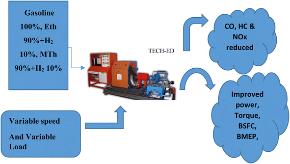 | ||
| Fig. 1 A diagram showing the multi-cylinder spark ignition engine fuelled with blended hydrogen with ethanol and blended hydrogen with methanol. | ||
| Engine | 3-Cylinder, 4-stroke gasoline engine with water cooling |
|---|---|
| Manufacturer | Marti Suzuki |
| Bore | 68.5 mm |
| Stroke size | 72 mm |
| Ratio of compression | 8.5![[thin space (1/6-em)]](https://www.rsc.org/images/entities/char_2009.gif) : :![[thin space (1/6-em)]](https://www.rsc.org/images/entities/char_2009.gif) 1 1 |
| Displacement | 796 cc |
| Ignition | Self-start |
| Ignition method | Spark ignition |
| Diameter of Orifice | 20 mm |
| Power rating | 12 kW |
| Speed | 2500 rpm |
2.1 Simulation setup
By joining multiple engine links, such as pipes, connections, resistances, catalytic converters, plenums, and air cleaners with multi-cylinder engines, the layout has been created using the one-dimensional simulation software AVL Boost to predict all of the performance parameters, combustion parameters, and emission characteristics, using simulation analysis according to future emissions requirements. Fig. 2 gives the overall modeling details of the multi-cylinder spark ignition engine using various connections for performing the simulation with various input parameters.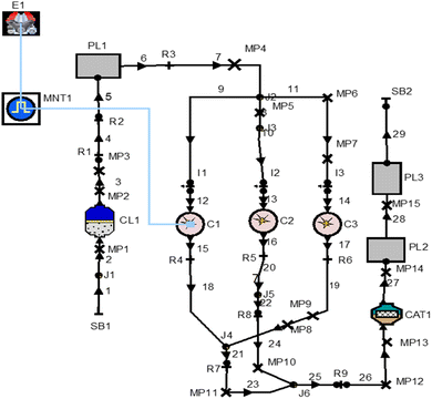 | ||
| Fig. 2 AVL Boost software's model of a one-dimensional, multi-cylinder spark-ignition engine diagram. | ||
3 Mathematical model
To produce complex dynamic interaction and interdependence among system variables, the internal combustion engine is a complicated mechanical process that integrates thermodynamics, chemical kinetics, heat transfer, transport phenomena, and fluid mechanics. It is challenging to understand complex connections and gain a deeper understanding of how these systems behave through simple laboratory experiments. One tool that has been used in the forefront in addressing this problem is the mathematical model for internal combustion engines. Since the advent of high-speed digital computers, numerical simulation of internal combustion engine operations has become increasingly crucial. The model's specifics influence whether the results are accurate. Large-scale models can consume many computer resources. As a result, it is necessary to choose between precision and computation time. Computer models correctly predict the behavior of the engine. This makes it simple for designers to alter the design and operational parameters on the computer, enabling them to analyze how the entire engine system will behave in a range of operating conditions. This kind of technique will lead to simpler optimization and less work during manufacture, which will reduce the scope of the inquiry, as well as shorten and lower the cost of engine testing.104 Combustion data
Three distinct combustion models exist for spark ignition engines: (1) the defined pattern to reflect the apparent rate of heat release (ROHR); (2) the single zone model; and (3) the multi-zone model. For a spark-ignition (SI) engine, combustion data typically include parameters like ignition timing, air–fuel ratio, combustion duration, and peak pressure. A brief overview is presented in the following section.Ignition timing: this is the crankshaft angle at which the spark plug fires. It is usually expressed in degrees before the piston reaches the top dead center (BTDC). The optimum ignition timing depends on factors like the engine speed, load, and fuel quality.
Air-fuel ratio (AFR): the AFR represents the mass ratio of air to fuel in the combustion mixture. For gasoline engines, a stoichiometric AFR is around 14.7![[thin space (1/6-em)]](https://www.rsc.org/images/entities/char_2009.gif) :
:![[thin space (1/6-em)]](https://www.rsc.org/images/entities/char_2009.gif) 1, but this can vary based on engine requirements and conditions.
1, but this can vary based on engine requirements and conditions.
Combustion duration: this is the time taken for the air-fuel mixture to burn completely. It is influenced by factors like the fuel properties, ignition timing, and turbulence in the combustion chamber.
Peak pressure: the maximum pressure reached during combustion. It is an essential parameter for assessing the engine performance and efficiency.
Burn rate: this refers to how quickly the air-fuel mixture burns after ignition. It can be influenced by factors like the turbulence, compression ratio, and fuel properties.
Heat release rate: this is the rate at which heat is released during combustion, and is often graphed over the crank angle. It provides insights into the combustion process.
These parameters can be influenced by factors like the engine design, fuel quality, and operational conditions. It is crucial to note that the combustion data are often experimentally determined through tests on engine dynamometers or simulations using computational models.
4.1 The specified heat release pattern
A simple heat release pattern was created,| m = mu + mb | (1) |
| dm/dθ = dmu/dθ + dmb/dθ = −dmu,CR/dθ – dmb,CR/dθ | (2) |
| V = Vu + Vb | (3) |
| PVu = mu + Ru + Tu | (4) |
| PVb = mb + Rb + Tb | (5) |
 | (6) |
 | (7) |
4.2 Single zone combustion models
The mixture in a single-zone combustion model is uniform and devoid of pressure or temperature gradients. The presumption is more in line with settings for high-speed engines, where swirl is anticipated to evenly combine the contents of the cylinders. A correlation involving direct injection and the degree of heat release has been found for direct injection engines.12,13 The process of fuel injection can be divided into a few straightforward steps. An elementary mathematical formula is used to prepare and burn the fuel that is injected at one of these processes.4.3 Multi-zone models
Although composition gradients and temperature were not taken into account, single-zone models still had issues with accurately predicting performance. Many two-zone and multi-zone models14 were produced as a result.Straightforward two-zone models presuppose that at all times during the burning process, the cylinder has a flaming zone and an incomplete combustion zone. The unburned zone is made up of the surrounding air, whereas the burning zone is composed of the fuel, combustion products, and air. Multi-zone variations divide the gasoline spray into a number of zones. Rates of preparation and burning for each zone were continuously observed.
Index b designates the burned area, whereas index u designates the unburned area. The flow of enthalpy is referred to as hudmb/d.
 | (8) |
Particularly at lower engine speeds, heat transfer during gas exchange in engines has a substantial impact on volumetric efficiency. Based on AVL experience and studies carried out at the Graz Technical University, the heat transmission model—particularly the Woschni model—has been modified to take this influence into account. The heat transfer coefficient is calculated from the following equation:16
| α = Max[αWoschini, 0.013d − 0.2P0.8T−0.53{C4(dind/)2|vin|}0.8] | (9) |
The atmosphere contains both nitrogen and oxygen, with a mole nitrogen content of 78% and an oxygen content of 21%. Eqn (7) describes the combustion of isooctane with air. The chemical formula for six-atom oxygen is C2H5OH, and it reacts with 3O2 to generate the ethanol that C2H5OH describes. 2CO2 and 3H2O are created when energy is given to the process in the form of a spark or heat. In this process, energy is also released. An illustration of the ethanol combustion process can be found below.
| C2H5OH + 3O2 = 2CO2 + 3H2O | (10) |
| C8H18 + 12.5O2 = 8CO2 + 9H2O | (11) |
| C8H18 + 12.5O2 + 12.5(3.76)N2 = 8CO2 + 9H2O + 12.5(3.76)N2 | (12) |
5 Results and discussion
Fig. 3 illustrates the power variations for blended methanol and ethanol with hydrogen fuel, comparing them with 100% gasoline. The highest power is observed in the case of 90% ethanol blended with 10% hydrogen and 90% methanol blended with 10% hydrogen, surpassing the power generated by 100% gasoline. Pure gasoline fuel consistently exhibits the lowest power across all engine speeds, followed by 90% methanol with 10% hydrogen fuel, and lastly, 90% ethanol blended with 10% hydrogen fuel. This trend is attributed to ethanol's higher oxygen content and superior combustion characteristics, resulting in increased power at higher blending ratios compared to methanol-blended fuel. The engine speed varies from 1500 to 5000 rpm, while maintaining a constant load of 100%. The escalation in engine speed enhances the air/fuel mixture in the combustion chamber, contributing to a higher number of cycles per unit time and subsequently generating more power at elevated speeds for all fuels. Notably, the 90% ethanol blended with 10% hydrogen fuel exhibits 16.6% more power than 100% gasoline and 11.11% higher power than methanol blended with hydrogen. Previous findings have also indicated that the addition of 10% hydrogen in methanol and ethanol results in a 3.49% and 5.02% increase in brake power at 1500 rpm, respectively.19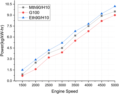 | ||
| Fig. 3 Effect of varying speeds on power using hydrogen-blended methanol and ethanol alternative fuels, with gasoline 100%. | ||
In Fig. 4, torque variations with engine speed are elucidated for 90% ethanol blended with 10% hydrogen, 90% methanol blended with 10% hydrogen, and 100% gasoline fuel. Torque represents the power plant's ability to generate power, and the discernible variations in this trend are noteworthy. The higher oxygen content in both ethanol and methanol enhances their combustion characteristics, contributing to improved torque output. The addition of 10% hydrogen plays a crucial role in augmenting the calorific value of the alcohol fuels, ultimately elevating the torque output of the blended fuel. Notably, 90% ethanol blended with 10% hydrogen fuel exhibits superior torque production. Specifically, the torque generated by the 90% ethanol and 10% hydrogen blend surpasses that of 100% gasoline fuel by 12.5% and exceeds methanol's 90% blended with 10% hydrogen fuel by approximately 6%. Previous findings have indicated that brake torque experienced a 7.77% and 16.73% increase with the addition of 10% hydrogen at 2000 rpm.20
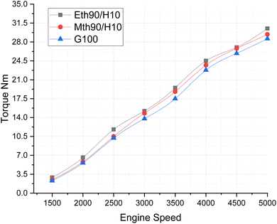 | ||
| Fig. 4 Effect of varying speeds on torque using hydrogen-blended methanol and ethanol alternative fuels, with gasoline 100%. | ||
In Fig. 5, the Brake Mean Effective Pressure (BMEP) illustrates variations for blended fuels—specifically, methanol 90% blended with 10% hydrogen, ethanol 90% blended with 10% hydrogen fuel and 100% gasoline—at different speeds of the multi-cylinder spark ignition engine. The notable observation is that BMEP attains its highest value for the 90% ethanol blended with 10% hydrogen fuel, followed by the 90% methanol blended with 10% hydrogen fuel. In contrast, 100% gasoline fuel exhibits a gradual increase in BMEP with the rise in engine speed. This pattern is attributed to the fact that the average BMEP value is highest for the ethanol 90% blended with 10% hydrogen fuel. Given that blended ethanol fuel also produces more power, this underscores its capacity to generate higher-pressure values. Consistent with previously published results, the addition of more hydrogen to methanol and ethanol has been shown to increase the BMEP of the engine, aligning with our findings.21
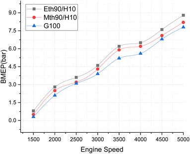 | ||
| Fig. 5 Effect of varying speeds on BMEP using hydrogen blended methanol and ethanol alternative fuels, with gasoline 100%. | ||
Fig. 6 illustrates the continuous decrease in the Brake Specific Fuel Consumption (BSFC) values for all fuel blends as the engine speeds increase. This acceleration in speed moves the mixture towards stoichiometric values, and then further towards the leaner side. Among the fuel blends, the lowest decrease in BSFC values is observed for 100% gasoline, followed by ethanol blended with hydrogen fuel, and then methanol with 90% hydrogen and 10% fuel. The elevated BSFC value for methanol blended with hydrogen fuel can be attributed to the fact that the blending of alcohol fuel with gaseous hydrogen slightly diminishes its heating value, contributing to the highest BSFC value at lower engine speeds. This is because engines using blended fuel require more fuel supply at the start of the engine, especially during the initial load, where a richer mixture is needed. Ethanol and methanol blended with hydrogen fuel combust rapidly at the beginning, leading to increased fuel consumption. The blend shifts towards a leaner composition, leading to a reduction in fuel supply.
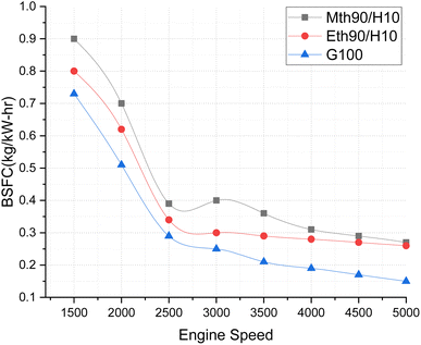 | ||
| Fig. 6 Effect of varying speeds on BSFC using hydrogen-blended methanol and ethanol alternative fuels, with gasoline 100%. | ||
At 1500 rpm, methanol with 90% and hydrogen with 10% exhibited a 12.5% higher BSFC than ethanol with 90% and hydrogen with 10%. A study by Zhi Tian et al. (2021)22 reported a reduction in BSFC by 31.51% and 24.6% at 1500 rpm for adding 10% hydrogen to methanol and ethanol, respectively. The greater decrease in BSFC values in the literature may be attributed to the investigation being conducted on a 4-cylinder engine, whereas the present study focuses on a 3-cylinder SI engine.23
6 Emissions
Fig. 7 compares the CO emissions from blended fuels and 100% gasoline at various speeds. The graph illustrates the variation for hydrogen 10% blended with 90% methanol and 90% ethanol fuels. The carbon monoxide emissions visibly increase with the rise in engine speed, ranging from 1500 to 5000 rpm. This elevation in CO-based emissions is a consequence of incomplete combustion at higher speeds.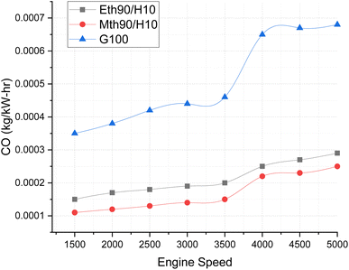 | ||
| Fig. 7 Effect of varying speeds on CO emissions using hydrogen-blended methanol and ethanol alternative fuels, with gasoline 100%. | ||
Notably, CO emissions are highest for gasoline fuel, surpassing those of blended fuels by approximately 12% to 13% at engine speeds between 3000 and 3500 rpm. Furthermore, the CO emissions for gasoline fuel escalate even more at higher speeds, reaching levels around 20% to 25% higher than those for ethanol 90% blended with 10% hydrogen fuel and methanol 90% blended with 10% hydrogen at 5000 rpm. Both ethanol and methanol blended with hydrogen fuel exhibit lower carbon-based emission values. This can be attributed to the molecular composition of ethanol and methanol, containing two and one carbon atoms, respectively, contributing to the decrease in CO emissions.24
Fig. 8 elucidates the hydrocarbon-based emissions across varying engine speeds. The graphic representation highlights that hydrocarbon emissions are more pronounced at lower speeds, and exhibit a continuous decrease with the augmentation of engine speeds. The maximum hydrocarbon emissions are recorded for 100% gasoline. Both alternative fuels exhibit significantly lower hydrocarbon-based emissions, approximately 66% lower at 1500 rpm for ethanol blended with hydrogen fuel compared to 100% gasoline, and around 70% lower for methanol blended with hydrogen fuel in comparison to 100% gasoline. Additionally, there is a continual reduction in hydrocarbon emissions as the engine speeds increase. This phenomenon can be attributed to the rapid combustion of fuel at higher engine speeds, leading to less fuel entering crevices and resulting in lower hydrocarbon emissions. Furthermore, at higher engine speeds, complete combustion is facilitated by an adequate supply of oxygen, as the mixture leans towards the more oxygen-rich side of the composition.25
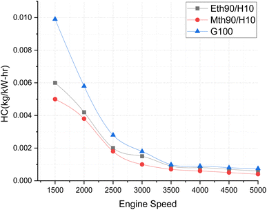 | ||
| Fig. 8 Effect of varying speeds on hydrogen emissions using hydrogen-blended methanol and ethanol alternative fuels, with gasoline 100%. | ||
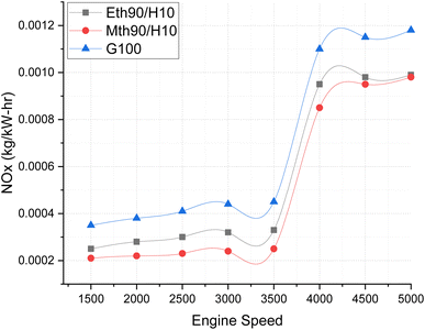
Fig. 9 illustrates the NOx emissions, providing a clear depiction of how NOx variation occurs across varying engine speeds. Almost all fuels exhibit a similar trend, with the highest NOx emissions observed for 100% gasoline. The increase in engine speed correlates with elevated NOx emissions.
 | ||
| Fig. 9 Effect of varying speeds on NOx emissions using hydrogen-blended methanol and ethanol alternative fuels, with gasoline 100%. | ||
Notably, up to 3500 rpm, the NOx emission values maintain a consistent trend, hovering around 0.0002 kg kW−1 h−1. However, beyond 3500 rpm, a drastic increase in NOx values is evident. This surge could be attributed to the escalating temperature within the combustion chamber at higher engine speeds. At elevated engine speeds, the air/fuel mixture combusts rapidly, and the addition of hydrogen fuel accelerates the combustion process even further due to its higher auto-ignition value. This heightened combustion raises the temperature, resulting in increased NOx formation.26
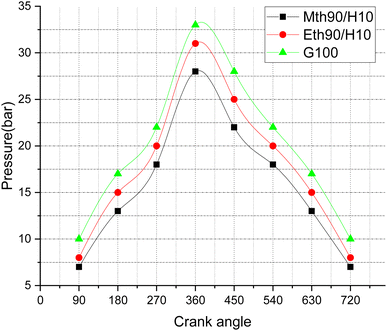
Fig. 10 illustrates pressure variations with respect to the crank angle, depicting the combustion pressure's fluctuations during the engine cycle. The peak pressure values exhibit an increase at different crank angle rotations. The highest peak pressure, reaching around 33 bar, is observed for 100% gasoline fuel. Following closely is 90% ethanol blended with 10% hydrogen, with pressure values in the range of approximately 31 bar, and finally, the blend of 90% methanol with 10% hydrogen displays peak pressure values around 27 bar. This trend can be attributed to the fact that conventional gasoline, with its higher heating values, generates more peak pressure compared to blended fuels, which slightly diminish their heating values, resulting in lower pressure values. The addition of 90% ethanol with 10% hydrogen fuel shows a 18.51% increase in pressure near the Top Dead Centre (TDC) compared to methanol blended with 10% hydrogen fuel. Additionally, gasoline exhibits 10% more peak pressure than ethanol blended with 10% hydrogen fuel. The maximum peak pressure for gasoline fuel is around 34 bar, close to TDC, while for ethanol and methanol blended with 10% hydrogen fuel, it is around 32 and 27 bar, respectively.
 | ||
| Fig. 10 Effect of varying speeds on pressure vs. crank angle using hydrogen-blended methanol and ethanol alternative fuels, with gasoline 100%. | ||
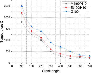
Fig. 11 depicts the temperature variations for 90% ethanol blended with 10% hydrogen fuel, 90% methanol blended with 10% hydrogen fuel, and 100% gasoline fuel. The observed trend can be attributed to the phenomenon that, at higher crank angles, the temperature experiences a decrease. During the initial stages of combustion, the mixture combusts more frequently and rapidly, leading to elevated temperatures of the combustion products. Consequently, the temperature values for the corresponding fuels are in the range of 2500 °C, 2200 °C, and 1800 °C.
 | ||
| Fig. 11 Effect of varying speeds on temperature using hydrogen-blended methanol and ethanol alternative fuels, with gasoline 100%. | ||
Conclusions
This research was conducted on a multi-cylinder spark ignition engine utilizing AVL Boost Software. It involved evaluating the performance and emission characteristics of two blends: 90% ethanol and 10% hydrogen, as well as 90% methanol and 10% hydrogen. Systematic comparisons were made with the performance and emissions of 100% gasoline fuel. The entire investigation utilized one-dimensional simulation software. Operating conditions included varying the engine speed while maintaining a constant load. Performance curves and emission formations were examined by adjusting the speed from 1500 to 5000 rpm, with the engine load consistently set at 100%. The results obtained led to the following conclusions.• A fuel blend of 90% ethanol and 10% hydrogen has demonstrated remarkable efficiency in both performance and emission control. This blend exhibited a 20% increase in power compared to pure gasoline and a 25% reduction in carbon monoxide (CO) emissions compared to a 100% gasoline fuel composition.
• A blend of 90% methanol and 10% hydrogen exhibited superior performance and emissions compared to 100% gasoline fuel. This combination demonstrated approximately 15% more power than a pure gasoline fuel composition.
• In the case of both ethanol and methanol blended fuels, the production of carbon monoxide (CO) and hydrocarbons (HC) is significantly lower compared to 100% gasoline fuel. Specifically, the CO emission levels for the 90% ethanol blended with 10% hydrogen demonstrated a reduction ranging from 10% to 20%, while the 90% methanol blended with 10% hydrogen exhibited a 25% decrease in CO emissions, particularly at lower loads.
• Likewise, in terms of hydrocarbon (HC) formations, the emissions displayed significantly lower values for both ethanol and methanol when blended with 10% hydrogen fuel. The levels of hydrocarbon formations were 70% less than those of 100% gasoline for ethanol blended with hydrogen fuel, and 75% less than gasoline for methanol blended with hydrogen fuel.
• NOx emissions were notably lower for methanol blended with 10% hydrogen fuel, especially at lower speeds. Similarly, ethanol blended with hydrogen fuel also exhibited significantly reduced NOx formations at lower engine speeds.
Abbreviations
| d in | Pipe diameter |
| v in | Port velocity coefficient |
| d | Cylinder diameter (m) |
| T | Cylinder temperature (K) |
| D/d | Diameter ratio (−) |
| mu | Unburned mass |
| L | Height of the cylinder (m) |
| L/D | Aspect ratio (−) |
| P | Dimensionless pressure (−) |
| α | Heat transfer coefficient (−) |
| m b | Burned mass |
| V | Free stream velocity (m s−1) |
| h u | Unburned enthalpy |
| h b | Burned enthalpy |
| C1 | Cylinder 1 |
| Mp1 | Measuring point 1 (−) |
| PL1 | Plenum 1 |
| CL1 | Cleaner 1 |
| CAT1 | Catalytic convertor 1 |
Data availability
This work was performed on AVL Boost Simulation software. The license for the software is brought by the National Institute of Technology Srinagar India. This work is purely based on one-dimensional simulation software works. The simulations were performed, and the results generated are reflected in the form of Plots. In addition, all other details are the part of the literature survey. Software details were collected from its manual, and the theory part is known through its theory detailed copy. For Mathematical modeling, the literature survey was conducted to understand how an engine works in open and closed systems using the First Law of Thermodynamics and continuity equations. All are mentioned in the references, and are cited in the corresponding Paper.Conflicts of interest
The Submission entitled “Numerical One-Dimensional Investigations on a Multi-cylinder Spark Ignition Engine using Hydrogen/Ethanol, Hydrogen/Methanol and Gasoline in Dual Fuel mode.” has no conflict of interest, and is entirely our original work performed in the laboratory.Acknowledgements
The author is grateful to the Sreenidhi Institute of Science and Technology, Department of Mechanical Engineering, that provided us with the laboratory facilities and encouraged us to perform research work based on our expertise. Our sincere thanks to AVL Austria Head Office and the branch office in India for providing the facility of AVL Boost Simulation Software. The author is also thankful to the National Institute of Technology Srinagar, which helped during the author's doctoral studies for doing innovative research work.References
- A. Yilancia, I. Dincer and H. K. Ozturk, A review on solar-hydrogen/fuel cell hybrid energy systems for stationary applications, Prog. Energy Combust. Sci., 2009, 35, 231–244 CrossRef.
- P. Karthik Selvan, M. M. Ajaylal, N. G. Maheshwaran and B. Sudharsan, Int. J. Eng. Res. Technol., 2018, 7(3), 362–365 Search PubMed , http://www.ijert.org. Theoretical Investigation on Ammonia as a Secondary fuel for IC Engines..
- V. Stefaan, S. Roger and V. Sebastian, Technical paper for students and young engineer's fisita world automotive congress, Barcelona. A High-Speed Single Cylinder Hydrogen Fuelled Internal Combustion Engine, 2004 Search PubMed.
- M. Kosar, B. Ozdalyan and M. B. Celik, The usage of hydrogen for improving emissions and fuel consumption in a small gasoline engine, J. Therm. Sci. Technol., 2011, 31, 101e8 Search PubMed.
- R. C. Green, L. Wang and M. Alam, The impact of plug-in hybrid electric vehicles on distribution networks: a review and outlook, Renew. Sustain. Energy Rev., 2011, 15, 544e53 CrossRef.
- P. K. Bose and D. Maji, An experimental investigation on engine performance and emissions of a single cylinder diesel engine using hydrogen as inducted fuel and diesel as injected fuel with exhaust gas recirculation, Int. J. Hydrogen Energy, 2009, 34, 4847e54 CrossRef.
- J. M. Gomes-Antunes, R. Mikalsen and A. P. Roskilly, An experimental study of a direct injection compression ignition hydrogen engine, Int. J. Hydrogen Energy, 2009, 34, 6516e22 CrossRef.
- C. Liew, H. Li, J. Nuszkowski, S. Liu, T. Gatts and R. Atkinson, et al., An experimental investigation of the combustion process of a heavy-duty diesel engine enriched with H2, Int. J. Hydrogen Energy, 2010, 35, 11357e65 CrossRef.
- S. Bari and M. M. Esmaeil, Effect of H2/O2 addition in increasing the thermal efficiency of a diesel engine, Fuel, 2010, 89, 378e83 CrossRef.
- T. Miyamoto, H. Hasegawa, M. Mikami, N. Kojima, H. Kabashima and Y. Urata, Effect of hydrogen addition to intake gas on combustion and exhaust emission characteristics of a diesel engine, Int. J. Hydrogen Energy, 2011, 36, 13138e49 Search PubMed.
- F. Xiao, A. Sohrabi and G. A. Karim, Effects of small amounts of fugitive methane in the air on diesel engine performance and its combustion characteristics, Int. J. Hydrogen Energy, 2008, 5, 334e45 Search PubMed.
- M. Aydin, A. Irgin and M. B. Çelik, The Impact of Diesel/LPG Dual Fuel on Performance and Emissions in a Single Cylinder Diesel Generator, Appl. Sci., 2018, 8, 825 CrossRef.
- N. H. Abdurahman, Y. M. Rosli, N. H. Azhari and A. A. Adam, The potential of a water-in-diesel emulsion for increased engine performance and as an environmentally friendly fuel, MATEC Web Conf., 2016, 70, 01003 CrossRef.
- M. Dubey and V. Saxena, Impact of emulsified water/diesel mixture on engine performance and environment, Int. J. Eng. Trends Technol., 2016, 36(9), 461–466 CrossRef.
- H. Patil and J. Waghmare, Biodiesel-water emulsions: an alternative approach for conventional fuels, Int. Res. J. Eng. Technol., 2017, 4(7), 1200–1204 Search PubMed.
- B. Zhang, C. Ji and S. Wang, Investigation on the lean combustion performance of a hydrogen enriched n-butanol engine, Energy Convers. Manage., 2017, 136, 36–43 CrossRef CAS.
- S. Raviteja and G. N. Kumar, Effect of hydrogen addition on the performance and emission parameters of an SI engine fuelled with butanol blends at stoichiometric conditions, Int. J. Hydrogen Energy, 2015, 40(30), 9563–9569 CrossRef CAS.
- S. Yousufuddin and M. Masood, Effect of ignition timing and compression ratio on the performance of a hydrogen-ethanol fuelled engine, Int. J. Hydrogen Energy, 2009, 34, 6945–6950 CrossRef CAS.
- T. Su, C. Ji, S. Wang, X. Cong and L. Shi, Research on performance of a hydrogen/n-butanol rotary engine at idling and varied excess air ratios, Energy Convers. Manage., 2018, 162, 132–138 CrossRef CAS.
- T. Su, C. Ji, S. Wang, L. Shi and X. Cong, Effect of ignition timing on performance of a hydrogen-enriched n-butanol rotary engine at lean condition, Energy Convers. Manage., 2018, 161, 27–34 CrossRef CAS.
- F. Meng, X. Yu, L. He, Y. Liu and Ye Wang, Study on combustion and emission characteristics of a n-butanol engine with hydrogen direct injection under lean burn conditions, Int. J. Hydrogen Energy, 2018, 43(15), 7550–7561 CrossRef CAS.
- X. Zhen, Z. Tian, Y. Wang, D. Liu and X. Li, A model to determine the effects of low proportion of hydrogen and the flame kernel radius on combustion and emission performance of direct injection spark ignition engine, Process Saf. Environ. Prot., 2021, 147, 1110–1124 CrossRef CAS.
- Bo Zhang, C. Ji and S. Wang, Investigation on the lean combustion performance of a hydrogen enriched n-butanol engine, Energy Convers. Manage., 2017, 136, 36–43 CrossRef CAS.
- P. Chitragar, K. Shiva Prasad and G. Kumar, Experimental Analysis of Four Cylinder 4-Stroke Gasoline Engine Using Hydrogen Fractions for Performance and Emission Parameters, SAE Technical Paper 2017-26-0063, 2017, DOI:10.4271/2017-26-0063.
- S. P. K. Vijayalakshmi, P. R. Chitragar and K. G. Narayanappa, Effect of hydrogen addition on combustion and emissions performance of a high-speed spark ignited engine at idle condition, Therm. Sci., 2018, 22(3), 1405–1413 CrossRef.
- L. P. Oommen, K. G. Narayanappa and S. K. Vijayalakshmi, Experimental Analysis of Synergetic Effect of Part-Cooled Exhaust Gas Recirculation on Magnetic Field-Assisted Combustion of Liquefied Petroleum Gas, Arab. J. Sci. Eng., 2020, 45, 9187–9196, DOI:10.1007/s13369-020-04696-z.
| This journal is © The Royal Society of Chemistry 2024 |
