 Open Access Article
Barium titanate photocatalysts with silver–manganese dual cocatalyst for carbon dioxide reduction with water†
Shuwei
Liu
 ,
Hongxuan
Qiu
 ,
Akira
Yamamoto
 and
Hisao
Yoshida
 *
*
Graduate School of Human and Environmental Studies, Kyoto University, Yoshida-nihonmatsu-cho, Sakyo-ku, Kyoto 606-8501, Japan. E-mail: yoshida.hisao.2a@kyoto-u.ac.jp
First published on 31st May 2024
Abstract
Titanate photocatalysts with suitable cocatalysts are promising candidates for photocatalytic CO2 reduction, with the use of water as an electron donor. Here, several barium titanates with various compositions were examined, and BaTi4O9 (BT4) was found to be the best photocatalyst with the assistance of an Ag cocatalyst for photocatalytic CO2 reduction to form CO. The photocatalytic activity was further enhanced by the use of MnOx as an additional cocatalyst to construct an Ag-MnOx/BT4 photocatalyst, where Ag and MnOx were selectively deposited at different facets on BT4 crystal and functioned as active sites for CO2 reduction and water oxidation, respectively. As for the oxidative products from water, molecular oxygen (O2) and hydrogen peroxide (H2O2) were obtained.
1. Introduction
Excess consumption of natural fossil resources has led to an increase in atmospheric greenhouse gases. Particularly, the high concentration of carbon dioxide (CO2) causing climate change has become a global issue,1 requiring the development of new technology to convert CO2 to valuable compounds without using fossil fuels.2 Artificial photosynthesis using water as a reductant is one such methodology to provide a sustainable global carbon cycle, where CO2 can be converted with solar energy into basic chemicals such as carbon monoxide (CO), formaldehyde, methanol, and methane.3,4 Among these possible products, CO is a useful compound because it is easily separated from the aqueous reaction solution, and it is well known as a component of the synthesis gas valuably utilized for the Fischer–Tropsch reaction.5,6 However, the efficiency of the energy conversion in photocatalysis remains far from satisfactory.In this photocatalytic reaction, CO2 is reduced through a reaction with protons and electrons to form CO (eqn (1)), which is competitive with hydrogen (H2) formation (eqn (2)). Water is oxidized to O2 (eqn (3)) or H2O2 (eqn (4)) and reproduced in the reductive reaction (eqn (1)).
| CO2 + 2H+ + 2e− → CO + H2O (−0.52 V vs. NHE, pH = 7.0) | (1) |
| 2H+ + 2e− → H2 (−0.41 V vs. NHE, pH = 7.0) | (2) |
| H2O + 2h+ → ½O2 + 2H+ (+0.81 V vs. NHE, pH = 7.0) | (3) |
| 2H2O + 2h+ → H2O2 + 2H+ (+1.35 V vs. NHE, pH = 7.0) | (4) |
Because the redox potential of H+/H2 is more positive than that of CO/CO2,7 it is difficult to selectively activate CO2 molecules in aqueous reaction conditions. Kudo and coworkers8 reported that CO2 can be predominantly reduced into CO even in water when silver nanoparticles (Ag NPs) serve as an efficient cocatalyst on the BaLa4Ti4O15 photocatalyst in the photocatalytic reduction of CO2, with water as an electron donor. Following this, many photocatalysts have been investigated, such as Ag/La2Ti2O7,9 Ag/Sr2KTa5O15,10 Ag/KCaSrTa5O15,11 Ag/ZnGa2O4,12 Ag/Ga2O3,13 Ag/ZnTa2O6,14 Ag/CaTiO3,15 and Ag/K2Ti6O13.16 However, it is imperative to develop new photocatalysts with higher energy conversion efficiency and reaction selectivity.
Plentiful works demonstrate that barium titanate materials, which are ferroelectric, inexpensive, and environmentally friendly,17 are promising candidates for the photodegradation of organic compounds,18–20 N2 reduction,21 and water splitting.22–24 It has been reported that BaTiO3 is an efficient photocatalyst for the CO2 photoreduction of CH4 and CO.25 Thus, other barium titanates with different compositions are also attractive to be examined for this photocatalytic reaction. Among these barium titanates, BaTi4O9 (BT4) with a pentagonal-prism tunnel structure, which brings out a significantly moderate distortion of TiO6 octahedra possibly leading to enhancement of the field polarization and efficient production of photoexcited charges,26,27 is a satisfactory photocatalyst for CO2 reduction.28 Thus, other barium titanates with different compositions may also be well-suited for this photocatalytic reaction.
Charge separation in photocatalyst crystals covered with facets is a beneficial and crucial method to increase the photocatalytic activity with less electron–hole recombination because photogenerated electrons and holes can migrate to respective facets to promote the reductive and oxidative reactions on the separated surface.29 For instance, Li et al. demonstrated that (010) facets prefer a reductive reaction, whereas (110) facets favour an oxidative reaction by loading metals (Au, Ag, Pt) and metal oxides (MnOx, PbO2), respectively, on the surface of monoclinic BiVO4 under light irradiation.30 It was verified that a cocatalyst deposited on reductive or oxidative facets selectively results in higher catalytic activity than a randomly dispersed cocatalyst.31 Our previous studies revealed that a combination of Ag-MnOx cocatalysts selectively loaded on a hexagonal rod-like K2Ti6O13 crystal photocatalyst with clear facets showed a high and selective activity for CO2 reduction,32 while the same dual cocatalyst loaded on a CaTiO3 photocatalyst converted CO2 and H2O to CO and H2O2,33 showing that the reaction selectivity depends on the combination of photocatalyst and cocatalyst.
In the present work, a series of barium titanates with different compositions was synthesized and loaded with Ag NP cocatalyst for subsequent examination of photocatalytic CO2 reduction with water. A higher CO formation rate with greater selectivity was obtained with an Ag/BT4 sample as compared to others. Thus, the preparation conditions for the BT4 photocatalyst were optimized, and an Ag-MnO2 dual cocatalyst was tested for BT4, which further enhanced the photocatalytic activity two-fold.
2. Experimental section
2.1 Preparation of samples
BT4 was fabricated by a solid-state reaction method according to a previous report.28 Briefly, BaCO3 (Rare Metallic Co., Ltd) and TiO2 (rutile, Kojundo Chemical Lab. Co., Ltd) were mixed with a molar ratio of Ba![[thin space (1/6-em)]](https://www.rsc.org/images/entities/char_2009.gif) :
:![[thin space (1/6-em)]](https://www.rsc.org/images/entities/char_2009.gif) Ti = 1
Ti = 1![[thin space (1/6-em)]](https://www.rsc.org/images/entities/char_2009.gif) :
:![[thin space (1/6-em)]](https://www.rsc.org/images/entities/char_2009.gif) 4 for 20 min in an alumina mortar in the presence of ethanol. The obtained powder was placed into an alumina crucible and heated in a muffle furnace, where the temperature was increased by a rate of 10 K min−1 from room temperature to 1173 K, 1273 K, or 1373 K (typically 1273 K) and maintained for 5, 10, 20, or 50 hours (typically 20 h), followed by cooling to room temperature. The BT4 samples calcined for x h at y K are referred to as BT4(x,y).
4 for 20 min in an alumina mortar in the presence of ethanol. The obtained powder was placed into an alumina crucible and heated in a muffle furnace, where the temperature was increased by a rate of 10 K min−1 from room temperature to 1173 K, 1273 K, or 1373 K (typically 1273 K) and maintained for 5, 10, 20, or 50 hours (typically 20 h), followed by cooling to room temperature. The BT4 samples calcined for x h at y K are referred to as BT4(x,y).
BaTinO2n+1 (n = 1, 5) and Ba2(n−1)Ti4n+1O10n (n = 2, 3, 4) were prepared by a solid state reaction method,24,34,35 while BaTi2O5 was synthesized by a flux method,36 as described in the ESI.†
The Ag cocatalyst was loaded on these barium titanate photocatalysts by a photodeposition (PD) method. The single Ag and single MnOx cocatalyst, or Ag and MnOx dual cocatalyst, were employed to modify the surface of the as-prepared BT4 by the PD or a simultaneous photodeposition (SPD) method, respectively. In these photodeposition methods, 2 g of BT4 sample was dispersed in 750 mL of ion-exchange water in an inner-irradiation reactor (Fig. S1†), and a certain amount of aqueous solution of Ag(NO3)3 (0.5 M), Mn(NO3)2 (0.1 M), or Ag(NO3)3 (0.5 M) and Mn(NO3)2 (0.1 M) was solely or simultaneously added to the suspension. After subjection to flowing argon with bubbling at a rate of 30 mL min−1 for 1.5 h in dark, the suspension was photoirradiated for 3 h using a high-pressure 100 W Hg lamp with Ar bubbling, where the lamp in a quartz cooling jacket connected to a water-cooling system was located at the centre of the reactor (Fig. S1†). Subsequently, the powder in the solution was filtered with suction and dried in an oven at 353 K overnight. An impregnation method (IMP) was also employed for Ag deposition, as shown in the ESI.†
2.2 Characterization
The crystal structure of each sample was determined by X-ray diffraction (XRD) with a Lab X XRD-6000 diffractometer (Shimadzu). Scanning electron microscopy (SEM) images were recorded by a field-emission scanning electron microscope (SU-8220, Hitachi, Japan), where elemental mappings were obtained by energy-dispersive X-ray spectroscopy (EDX, 15.0 kV). Diffuse reflectance (DR) UV–Vis spectroscopy of the prepared samples was performed using a V-570 (JASCO) instrument at room temperature with BaSO4 as a reference. The compositions of cocatalysts in the samples were evaluated by X-ray fluorescence (XRF) analysis with an EDX-8000 spectrometer (Shimadzu) in accordance with each calibration curve obtained by reference samples prepared by an impregnation method. The Brunauer–Emmett–Teller (BET) specific area was evaluated with a Monosorb (Quantachrome) at 77 K. Ag and Mn K-edge X-ray absorption spectra (XAS) were recorded at NW-10A in transmission mode and BL-9A in fluorescence mode of the Photon Factory (KEK, Tsukuba, Japan), respectively.2.3 Photocatalytic reaction
Photocatalytic reaction tests were carried out in the inner-irradiation vessel (Fig. S1†). The photocatalyst of 1.0 g was placed into the reactor with 750 mL ion-exchanged water containing 0.5 M NaHCO3 as a buffer, and the solution was magnetically stirred without irradiation under a CO2 flow with a flow rate of 30 mL min−1 for 1.5 h to purge the reactor. After initiating the photoirradiation with a 100 W Hg lamp (approximately 8.2 mW cm−2 measured at 360 ± 10 nm in wavelength) located at the centre of the reactor, the temperature was maintained at 283 K in the reactor with a flow of cool water. The products in the outflowing gas from the reactor were sampled at each scheduled time and analysed by online gas chromatography (Shimadzu, GC-8A, TCD, Shincarbon ST column, argon carrier). Typically, the data recorded after 3 h from the start of photoirradiation were employed for discussion. The primary gaseous products were limited to H2, O2 and CO, while the compound analysed from the liquid phase was limitted to H2O2.Because there is no other reductive product in the present work, the selectivity toward CO evolution, SCO was calculated by eqn (5). The ratio of consumed electrons and holes, R(e−/h+), in the process of CO2 photoreduction is defined by eqn (6).
| SCO(%) = 100 × RCO/(RH2 + RCO) | (5) |
| R(e−/h+) = (RCO + RH2)/(2RO2 + RH2O2) | (6) |
The formation rates of CO, H2, O2, and H2O2 are referred to as RCO, RH2, RO2, and RH2O2, respectively. It is worthy to know that the value of R(e−/h+) should be unity because of the same amount of photogenerated electrons and holes.
3. Results and discussion
3.1. Various barium titanates
Fig. S2† shows the XRD patterns of the barium titanate samples, BaTinO2n+1 (n = 1, 2, 4, and 5) and Ba2(n−1)Ti4n+1O10n (n = 2, 3, and 4). According to previous studies, most of these barium titanates including BaTiO3 (BT), Ba6Ti17O40 (B6T17), Ba4Ti13O30 (B4T13), and Ba2Ti9O20 (B2T9) can be successfully synthesized without an impurity phase,24,28,34 except for BaTi4O9 (BT4), BaTi2O5 (BT2), and BaTi5O11 (BT5). It was also noted that there was a tiny impurity phase of BaTiO3 in the BT4 sample. The prepared BT2 sample included a certain amount of BaTiO3 phase as an impurity.In the phase diagram, the BaTi2O5 phase can be found in a very narrow temperature window, which demonstrates its thermodynamically stability between 1220 and 1230 °C (1493–1503 K).37 This indicates the requirement for further precise control of conditions to yield the pure BT2 phase due to the limited thermodynamic stability. Under the present conditions, the BT5 sample could not be successfully synthesized, and the obtained material was a mixture of the BaTi4O9 phase and others, such as a trace amount of BaTiO3 phase. A possible reason for this may be inhomogeneous mixing or uneven diffusion of the elements in the solid-state reaction due to insufficient heating time.38
Fig. 1 shows the DR UV–Vis spectra of the prepared barium titanate samples, which provides evidence that these materials can be excited by UV light.
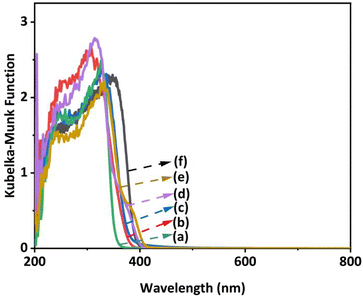 | ||
| Fig. 1 DR UV–Vis spectra of the prepared samples: (a) B4T13, (b) BT2, (c) B6T17, (d) BT4, (e) B2T9, and (f) BT. | ||
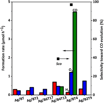
After loading Ag cocatalyst of 1 wt% on these samples (except for the BT5 sample), their performances for the photocatalytic conversion of CO2 with water were evaluated. Fig. 2 shows the formation rates of H2, O2, and CO and selectivity for CO (SCO) for the prepared photocatalysts. The BT, BT2, B6T17, and B2T9 samples loaded with the Ag cocatalyst showed trace amounts of H2 and O2 evolution. There was CO formation with low CO selectivity (SCO = 39%) for the Ag/B4T13 sample. Ag/BT4 showed a prominent CO production rate of 4.5 μmol h−1 among these Ag-loaded samples. This is the first report examining these six types of barium titanates for photocatalytic CO2 reduction with water, and only the Ag/BT4 sample exhibited selective photocatalytic activity for CO2 reduction to CO, with high selectivity of SCO = 97%.
The origin of the high photocatalytic performance of the Ag/BT4 sample is discussed here. From the DR UV-Vis spectra of the bare barium titanate samples (except for BT5) (Fig. 1), the bandgap was estimated using a Tauc plot39 for each sample, as shown in Fig. S3† and listed in Table S1.† Assuming the tops of the valence bands of these barium titanates are near to each other,40 the bottom of the conduction band was tentatively estimated (Table S1†). When compared to the redox potential of CO2/CO (Fig. S4†), the photoexcited electrons in the valence band of the BT4 and B4T13 samples were expected to be able to reduce CO2 to CO, and the activity of the BT4 photocatalyst was expected to be higher than that of B4T13, due to the greater negative potential of the excited electrons, which was consistent with the results (Fig. 2).
From a structural point of view, the structure of BT4 is unique, consisting of a pentagonal prism tunnel with structural distortion that provides a unique internal electric field that might reduce the recombination of the photoexcited electrons and holes.24 Lin et al. proposed a correlation between the packing factor (PF) and photocatalytic activity among antimonate photocatalysts,41i.e., the crystal of lower PF provides higher photocatalytic activity. The lowest PF among these six barium titanates is for BT4 (Table S2†), which exhibited the highest activity. At present, the origin of the high photocatalytic activity of the Ag/BT4 photocatalyst is unknown, and requires further detailed study.
Because the BT4 sample showed the highest photocatalytic activity among these obtained barium titanate photocatalysts, the study was continued with BT4. This does not preclude the possibility that the remaining barium titanates with other compositions may exhibit a high photocatalytic activity for CO2 reduction after further optimization.
3.2. Preparation conditions for BaTi4O9
The optimization of BT4 was conducted by altering the calcination conditions. Fig. S5† shows the XRD patterns of the prepared BT4(x,1273) samples under different holding times of 5–50 h, at 1273 K. The primary diffractions of the prepared samples are identical to that of the BaTi4O9 phase (ICSD #49575), and the diffraction intensities were similar to each other, which indicates that no difference was found according to XRD. It is noted that a trace amount of BaTiO3 as an impurity phase was detected in all the BT4(x,1273) samples. A possible reason for this phenomenon may be the different melting temperatures, i.e., the mixture of BaO + TiO2 melts more easily than that of BaO + 4TiO2 during calcination.42 In addition, most of the samples showed tiny diffractions from rutile TiO2, an impurity phase, while no diffractions from BaCO3 were found, meaning that unreacted TiO2 remained as a crystallite, while unreacted Ba species possibly existed as BaCO3 with very small crystallites or an amorphous phase.Fig. 3 shows SEM images of the BT4(x,1273) samples prepared with different holding times. When the holding times were short, such as 5 h and 10 h, irregularly shaped BT4 particles agglomerated, and the characteristic polyhedral morphology could not form because of the insufficient calcination time. With increasing holding time such as 20 h and 50 h, the edge of the polyhedral BT4 crystal became clearer, suggesting that the facet junctions of BT4 clearly appeared, and the crystal sizes were larger by the order of several hundreds of nanometres.
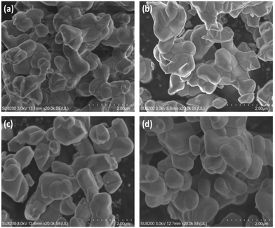 | ||
| Fig. 3 SEM images of the BT4(x,1273) samples prepared by different holding times (x) of (a) 5, (b) 10, (c) 20, and (d) 50 h. Calcination was carried out at 1273 K. | ||
Fig. S6† presents the XRD patterns of the BT4(20,y) samples prepared at different temperatures under the same holding time of 20 h. The diffraction peaks of all the samples are consistent with the BaTi4O9 phase, although the calcination temperature is different. However, the impurity phase of BaTiO3 did not disappear, and thus, the parameters of holding time or calcination temperature are not crucial for removing the impurity phase in the BT4(20,y) samples. The BT4(20,1173) sample showed diffractions with relatively low intensity compared with other BT4(20,y) samples calcined at higher temperatures. As shown in the SEM image (Fig. S7†), the BT4(20,1173) sample contained some smaller particles that might be incompletely crystallised. With increasing calcination temperature, the size of the BT4 particles increased from a hundred nanometres to one micrometre, and the shape became more regular.
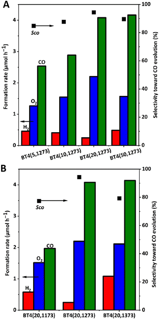
Fig. 4 shows the results of the photocatalytic reaction tests for these BT4(x,y) samples with 1 wt% of Ag cocatalyst. Among the BT4(x,1273) samples prepared at 1273 K with different holding times (Fig. 4A), a relatively high CO formation rate was obtained for the BT4(20,1273) sample, with the highest selectivity for CO compared with the samples calcined under other holding times. Particularly, the photocatalytic performance was enhanced 1.6 times for the BT4(20,1273) sample compared with the BT4(5,1273) sample. Among the BT4(20,y) samples calcined at various temperatures for 20 h, the BT4(20,1273) sample exhibited the highest formation rate with the highest selectivity for CO evolution of 94.3% (Fig. 4B). Therefore, the optimum synthesis conditions were determined to be 1273 K for 20 h, and further study was conducted with the BT4 sample synthesized under these conditions, i.e., the BT4(20,1273) sample.
In many cases, specific surface area (SSA) is an important factor that affects the quantity of catalytic active sites on the surface of a photocatalyst, leading to different photocatalytic activities. The SSAs of these BT4(x,y) samples are listed in Table S3.† The results suggest that there is higher photocatalytic activity for the BT4 samples with smaller specific surface areas, such as Ag/BT4(20,1273) and Ag/BT4(50,1273) (Table S3,† entries 3 and 4), which is in agreement with the case of K2Ti6O13, as reported in our previous work.43–45 Larger particles with less SSA would have the advantage of a large cross-sectional area for photoabsorption, and would exhibit higher photocatalytic activity in photocatalysis using multielectrons such as CO2 reduction with water oxidation (eqn (1) and (3)).43 The other possible reasons for the difference in photocatalytic activity would be the high crystallinity and clear morphology with facets, as supported by XRD and SEM images, which will be discussed later. However, the BT4(20,1373) sample with the smallest SSA exhibited low photocatalytic activity (Table S3,† entry 6), which showed that the SSA is not the sufficient condition, but one of the requirements.
3.3. Dual cocatalyst for BaTi4O9
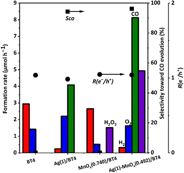
Photocatalytic reaction tests were performed over the BT4 samples with different cocatalysts Ag, MnOx, and Ag-MnOx, as shown in Fig. 5. Bare BT4 was confirmed as a satisfactory photocatalyst for water splitting, with stoichiometric evolution of H2 and O2.23 As expected, it was confirmed that the Ag/BT4(20,1273) sample produced CO and O2 with a high formation rate and high CO selectivity of 94%.28 It was found that the MnOx/BT4(20,1273) sample exhibited a similar H2 formation rate, but less O2 formation compared with bare BT4(20,1273). Thus, the resulting solution was filtered after the photocatalytic reaction, and was then used for the detection of H2O2 formation by potassium permanganate titration, which is a conventional method for testing H2O2 formation.33From the results shown in Fig. S8,† H2O2 was proved as a possible oxidative product. This confirmed that the MnOx cocatalyst contributed to H2O2 formation (eqn (4)), and indicated that the MnOx cocatalyst on BT4 can function as a cocatalyst for water oxidation with holes. The formation of hydrogen peroxide has also been reported for Ag-MnOx/CaTiO3![[thin space (1/6-em)]](https://www.rsc.org/images/entities/char_2009.gif) 33 and Ag-CoOx/CaTiO3
33 and Ag-CoOx/CaTiO3![[thin space (1/6-em)]](https://www.rsc.org/images/entities/char_2009.gif) 46 in photocatalytic CO2 reduction with water in aqueous solution of NaHCO3. The CO formation rate for the Ag-MnOx/BT4(20,1273) sample was 2 times higher than that of the Ag/BT4(20,1273) sample. The O2 production rate was less than half of the CO formation rate, and production of H2O2 was found. In the calculation with formed H2O2, the R(e−/h+) value was nearly unity (Fig. 5). In a long-time reaction test with the Ag-MnOx/BT4(20,1273) sample (Fig. S9†), after the initial period of 3.5 h, the formation rates for the products became constant, which indicated the stability of the photocatalyst.
46 in photocatalytic CO2 reduction with water in aqueous solution of NaHCO3. The CO formation rate for the Ag-MnOx/BT4(20,1273) sample was 2 times higher than that of the Ag/BT4(20,1273) sample. The O2 production rate was less than half of the CO formation rate, and production of H2O2 was found. In the calculation with formed H2O2, the R(e−/h+) value was nearly unity (Fig. 5). In a long-time reaction test with the Ag-MnOx/BT4(20,1273) sample (Fig. S9†), after the initial period of 3.5 h, the formation rates for the products became constant, which indicated the stability of the photocatalyst.
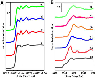
The chemical states of the dual cocatalyst of Ag and Mn species were investigated by X-ray adsorption spectroscopy (XAS). Fig. 6A shows the Ag K-edge X-ray absorption near edge structure (XANES) of the prepared samples and corresponding references, Ag foil, and Ag2O. The shape and intensity of XANES with the first peak at 25![[thin space (1/6-em)]](https://www.rsc.org/images/entities/char_2009.gif) 526 eV for the samples were in good agreement with that of Ag foil, but were clearly distinguished from that of Ag2O (Fig. 6A and S10†), revealing that the Ag cocatalyst existed in the form of metallic Ag in the Ag(1)/BT4(20,1273) and Ag(1)-MnOx(0.492)/BT4(20,1273) samples. This suggests that the simultaneous deposition of Mn species would not influence the metallic state of the Ag cocatalyst.
526 eV for the samples were in good agreement with that of Ag foil, but were clearly distinguished from that of Ag2O (Fig. 6A and S10†), revealing that the Ag cocatalyst existed in the form of metallic Ag in the Ag(1)/BT4(20,1273) and Ag(1)-MnOx(0.492)/BT4(20,1273) samples. This suggests that the simultaneous deposition of Mn species would not influence the metallic state of the Ag cocatalyst.
As for the Mn species deposited on the prepared samples (Fig. 6Be and f), the spectra shapes were not strictly consistent with Mn foil or any state of typical manganese oxides including MnO, Mn2O3, and MnO2 (Fig. 6Ba–d). In detail, the main peak at 6559 eV was similar to that for MnO2 (Fig. 6Bd), while the edge at 6543 eV was likely that for Mn2O3 (Fig. 6Bc), meaning that the Mn2+ precursor was likely oxidized to a mixture of Mn3+ and Mn4+. It was noted that the XANES of MnOx(0.580)/BT4(20,1273) and Ag(1)-MnOx(0.492)/BT4(20,1273) were similar to each other, indicating that the addition of silver will not greatly affect the chemical state of the MnOx species. Thus, the MnOx species deposited on the surface of BT4 by the photodeposition (PD and SPD) method exhibited a unique feature and local structure that was different from those of typical manganese oxides used as references regardless of the photodeposition of Ag species.
The location of photodeposited metal and metal oxide species assist in understanding the function of the facets of the photocatalyst crystals, as mentioned above.47 The morphology of the BT4(20,1273) crystal was typically that of rectangular or cylindrical crystals (Fig. 7, S7 and S11†), and it was not well controlled at present. When the Ag cocatalyst was photodeposited on the cylindrical BT4(20,1273) crystal (Fig. 7a), Ag NPs were formed on the sides of the cylindrical BT4 crystals. Namely, photogenerated electrons migrated to these facets, and the reduction of Ag+ cations preferentially took place on these facets to form metallic Ag nanoparticles, while the photogenerated holes oxidized water, as described by eqn (7) and (8):
| Ag+ + e− → Ag | (7) |
| 2H2O + 4h+ → O2 + 4H+ | (8) |
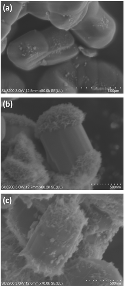 | ||
| Fig. 7 SEM images of the samples: (a) Ag(1)/BT4, (b) MnOx(2.4)/BT4, and (c) Ag(1.499)-MnOx(0.523)/BT4. The BT4 sample used was BT4(20,1273). | ||
When the MnOx cocatalyst was photodeposited with sodium iodoxide (NaIO3) as a sacrificial reagent (electron acceptor), petal-like MnOx species were selectively formed on the top and bottom of the cylindrical BT4 crystal (Fig. 7b), and the places and morphology were clearly different from those of photodeposited Ag NPs (Fig. 7a). The MnOx cocatalyst was deposited through oxidation of Mn(II) cations with positive holes on the oxidative facets (eqn (9) and (10)), where MnO2 is representatively used in the equation instead of MnOx:
| Mn2+ + 2h+ + 2H2O → MnO2 + 4H+ | (9) |
| IO3− + 6e− + 6H+ → I− + 3H2O | (10) |
When these Ag and MnOx cocatalysts were deposited as a dual cocatalyst using the SPD method (Fig. 7c), the side and top/bottom were selectively decorated with Ag NPs and MnOx species, respectively, resulting in full coverage of the cylindrical BT4 crystal. Thus, we can recognize the position of the reductive and oxidative facets according to the position of the Ag NPs and MnOx species, as shown in Fig. 7. This indicates that the photoexcited electrons can preferentially migrate to the Ag NPs, and the photoformed holes can dominantly move to the MnOx species. The photocatalytic activity was actually enhanced by the selectively photodeposited Ag and MnOx cocatalysts (Fig. 5). Therefore, we can draw the conclusion that the charge transfer to certain facets promotes the reaction, as shown in Fig. 8.
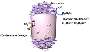 | ||
| Fig. 8 Schematic drawing of photocatalytic CO2 reduction with water as an electron donor on the Ag-MnOx/BT4 crystal photocatalyst. | ||
These observations revealed that the side and top/bottom of the cylindrical BT4 crystal are the reductive and oxidative facets, respectively. This fact was further confirmed on the rectangular-shaped BT4(20,1273) crystals by photodeposition of Pt4+ and Pb2+, as shown in Fig. S11.†
It was reported that although the interaction between Ag and Mn species will disturb CO2 photoreduction with H2O, the facet-selective photodeposition of Ag and Mn species prevented the interaction between Ag and Mn species, which led to the high photocatalytic performance.46 Because the photocatalytic activity was enhanced (Fig. 5), it could be considered that the Ag nanoparticles on the reductive facets and the MnOx on the oxidative facets play important roles in the photocatalytic performance. The selective photodeposition of the Ag-MnOx dual cocatalyst on the present BT4 crystals greatly improved the photocatalytic activity, and the property of the MnOx species changed the selectivity for the oxidation with holes to form H2O2.
3.4. Proposed mechanism
As mentioned above, in the photodeposition of the cocatalysts on the BT4 crystal, Ag+ cations are reduced by the photoexcited electrons and then deposited as Ag NPs on the reductive facet of the BT4 crystal, while Mn2+ cations are oxidized by the holes to form petal-like MnOx species on the oxidative facets. Thus, in the photocatalytic reaction with the Ag-MnOx/BT4 photocatalyst, the photoexcited electrons will reach the Ag NPs, and holes will go to the MnOx species to promote the reductive and oxidative reactions, respectively. Ag selectively promotes CO2 photoreduction to CO (eqn (1)), while MnOx promotes the oxidation of water to O2 or H2O2 (eqn (3) and (4)). Thus, the Ag and MnOx species can individually participate in CO2 photoreduction and water oxidation, as illustrated in Fig. 8. The efficient consumption of electrons and holes reduces recombination, resulting in high photocatalytic performance.4. Conclusions
Several barium titanate compounds with different compositions were prepared for examination. BaTinO2n+1 (n = 1, 4) and Ba2(n−1)Ti4n+1O10n (n = 2, 3, 4) were prepared by a solid-state reaction method, and BaTi2O5 was prepared by a flux method, while pure BaTi5O11 was not obtained under the present conditions. Among the prepared barium titanates, it was demonstrated that BaTi4O9 (BT4) was a satisfactory photocatalyst for CO2 reduction with water. The formation of clear reductive and oxdiative facets on the cylindrical (or rectangular) BT4 crystals was realized by optimization of preparation conditions for BT4.When an Ag-MnOx dual cocatalyst is loaded by the photodeposition method, Ag NPs and petal-like MnOx species are separately loaded on the reductive and oxidative facets, respectively. Such prepared Ag-MnOx/BT4 crystal photocatalysts can exhibit excellent photocatalytic activity for CO2 reduction with water, where CO is formed as a reduction product, and O2 and H2O2 are formed as oxidation products.
This work demonstrates the potential of BaTi4O9 crystal to act as a photocatalyst, and the efficient property of the Ag-MnOx dual cocatalyst for the BT4 photocatalyst, which will contribute to the further development of photocatalysts for CO2 reduction with water to obtain CO as a valuable intermediate for industrial chemistry by utilization of solar energy.
Author contributions
Shuwei Liu: conceptualization, investigation, writing – original draft. Hongxuan Qiu: conceptualization, investigation, methodology. Akira Yamamoto: investigation, methodology, funding acquisition. Hisao Yoshida: conceptualization, funding acquisition, project administration, supervision, writing – review and editing.Conflicts of interest
There are no conflicts to declare.Acknowledgements
The XAFS spectra of the samples were measured at the NW10A and BL-9A of the Photon Factory (PF) with the approval of the Photon Factory Program Advisory Committee (proposal number 2022G549). This study was financially supported by the Joint Usage/Research Center for Catalysis (23DS0423) and a Grant-in-Aid for Scientific Research (B) (21H01975) from the Japan Society for the Promotion of Science (JSPS).References
- G. A. Florides and P. Christodoulides, Environ. Int., 2009, 35, 390–401 CrossRef CAS PubMed.
- J. Zhao, X. Wang, Z. Xu and J. S. C. Loo, J. Mater. Chem. A, 2014, 2, 15228–15233 RSC.
- H. Huang, J. Zhao, B. Weng, F. Lai, M. Zhang, J. Hofkens, M. B. J. Roeffaers, J. A. Steele and J. Long, Angew. Chem., Int. Ed., 2022, 61, e202204563 CrossRef CAS PubMed.
- S. Wang, X. Han, Y. Zhang, N. Tian, T. Ma and H. Huang, Small Struct., 2020, 2, 2000061 CrossRef.
- S. Abello and D. Montane, ChemSusChem, 2011, 4, 1538–1556 CrossRef CAS PubMed.
- D. K. Chauhan, N. Sharma and K. Kailasam, Mater. Adv., 2022, 3, 5274–5298 RSC.
- R. Pang, K. Teramura, H. Tatsumi, H. Asakura, S. Hosokawa and T. Tanaka, Chem. Commun., 2018, 54, 1053–1056 RSC.
- K. Iizuka, T. Wato, Y. Miseki, K. Saito and A. Kudo, J. Am. Chem. Soc., 2011, 133, 20863–20868 CrossRef CAS PubMed.
- Z. Wang, K. Teramura, S. Hosokawa and T. Tanaka, Appl. Catal., B, 2015, 163, 241–247 CrossRef CAS.
- Z. Huang, K. Teramura, S. Hosokawa and T. Tanaka, Appl. Catal., B, 2016, 199, 272–281 CrossRef CAS.
- T. Takayama, A. Iwase and A. Kudo, Bull. Chem. Soc. Jpn., 2015, 88, 538–543 CrossRef CAS.
- Z. Wang, K. Teramura, S. Hosokawa and T. Tanaka, J. Mater. Chem. A, 2015, 3, 11313–11319 RSC.
- M. Yamamoto, T. Yoshida, N. Yamamoto, T. Nomoto, Y. Yamamoto, S. Yagi and H. Yoshida, J. Mater. Chem. A, 2015, 3, 16810–16816 RSC.
- S. Iguchi, K. Teramura, S. Hosokawa and T. Tanaka, Catal. Sci. Technol., 2016, 6, 4978–4985 RSC.
- A. Anzai, N. Fukuo, A. Yamamoto and H. Yoshida, Catal. Commun., 2017, 100, 134–138 CrossRef CAS.
- X. Zhu, A. Yamamoto and H. Yoshida, Dalton Trans., 2021, 50, 7976–7983 RSC.
- G. Panthi and M. Park, J. Energy Chem., 2022, 73, 160–188 CrossRef CAS.
- X. Zhang, X. Wang, J. Chai, S. Xue, R. Wang, L. Jiang, J. Wang, Z. Zhang and D. D. Dionysiou, Appl. Catal., B, 2020, 272, 119017 CrossRef CAS.
- Y. Cui, J. Briscoe, Y. Wang, N. V. Tarakina and S. Dunn, ACS Appl. Mater. Interfaces, 2017, 9, 24518–24526 CrossRef CAS PubMed.
- H. Fan, H. Li, B. Liu, Y. Lu, T. Xie and D. Wang, ACS Appl. Mater. Interfaces, 2012, 4, 4853–4857 CrossRef CAS PubMed.
- Z. Zhao, D. Wang, R. Gao, G. Wen, M. Feng, G. Song, J. Zhu, D. Luo, H. Tan, X. Ge, W. Zhang, Y. Zhang, L. Zheng, H. Li and Z. Chen, Angew. Chem., Int. Ed., 2021, 60, 11910–11918 CrossRef CAS PubMed.
- Y. Yamashita, M. Tada, M. Kakihana, M. Osada and K. Yoshida, J. Mater. Chem., 2002, 12, 1782–1786 RSC.
- Y. Hiramachi, H. Fujimori, A. Yamakata and Y. Sakata, ChemCatChem, 2019, 11, 6213–6217 CrossRef CAS.
- M. Kohno, T. Kaneko, S. Ogura, K. Sato and Y. Inoue, J. Chem. Soc., Faraday Trans., 1998, 94, 89–94 RSC.
- G. Yang, J. Xiong, M. Lu, W. Wang, W. Li, Z. Wen, S. Li, W. Li, R. Chen and G. Cheng, J. Colloid Interface Sci., 2022, 624, 348–361 CrossRef CAS PubMed.
- M. Kohno, S. Ogura and Y. Inoue, J. Mater. Chem., 1996, 6, 1921–1924 RSC.
- Y. Inoue, T. Niiyama, Y. Asai and K. Sato, J. Chem. Soc., Chem. Commun., 1992, 579–580 RSC.
- A. Anzai, A. Yamamoto and H. Yoshida, Catal. Lett., 2021, 152, 2498–2506 CrossRef.
- T. Ohno, K. Sarukawa and M. Matsumura, New J. Chem., 2002, 26, 1167–1170 RSC.
- R. Li, F. Zhang, D. Wang, J. Yang, M. Li, J. Zhu, X. Zhou, H. Han and C. Li, Nat. Commun., 2013, 4, 1432 CrossRef PubMed.
- J. Zhu, F. Fan, R. Chen, H. An, Z. Feng and C. Li, Angew. Chem., Int. Ed., 2015, 54, 9111–9114 CrossRef CAS PubMed.
- X. Zhu, A. Yamamoto, S. Imai, A. Tanaka, H. Kominami and H. Yoshida, Chem. Commun., 2019, 55, 13514–13517 RSC.
- T. Soltani, A. Yamamoto, S. P. Singh, A. Anzai, E. Fudo, A. Tanaka, H. Kominami and H. Yoshida, ACS Appl. Energy Mater., 2021, 4, 6500–6510 CrossRef CAS.
- E. Song, D. H. Kim, E. J. Jeong, M. Choi, Y. Kim, H. J. Jung and M. Y. Choi, Environ. Res., 2021, 202, 111668 CrossRef CAS PubMed.
- S. Zhu, Y. Dai and X. Pei, J. Mater. Sci.: Mater. Electron., 2022, 33, 16406–16413 CrossRef CAS.
- J. Fu, Y. Hou, M. Zheng and M. Zhu, CrystEngComm, 2017, 19, 1115–1122 RSC.
- H. Zhou, H. Wang, Y. Chen, K. Li and X. Yao, J. Am. Ceram. Soc., 2008, 91, 3444–3447 CrossRef CAS.
- Y. Miseki and A. Kudo, ChemSusChem, 2010, 4, 245–251 CrossRef PubMed.
- J. Tauc, R. Grigorovici and A. Vancu, Phys. Status Solidi, 1966, 15, 627–637 CrossRef CAS.
- D. E. Scaife, Sol. Energy, 1980, 25, 41–54 CrossRef CAS.
- X. Lin, J. Wu, X. Lu, Z. Shan, W. Wang and F. Huang, Phys. Chem. Chem. Phys., 2009, 11, 10047–10052 RSC.
- D. E. Rase and R. Roy, J. Am. Ceram. Soc., 2006, 38, 102–113 CrossRef.
- T. Ishii, R. Takioka, H. Yasumura, A. Yamamoto and H. Yoshida, Catal. Today, 2024, 429, 114476 CrossRef CAS.
- H. Yoshida, L. Zhang, M. Sato, T. Morikawa, T. Kajino, T. Sekito, S. Matsumoto and H. Hirata, Catal. Today, 2015, 251, 132–139 CrossRef CAS.
- H. Yoshida, M. Sato, N. Fukuo, L. Zhang, T. Yoshida, Y. Yamamoto, T. Morikawa, T. Kajino, M. Sakano, T. Sekito, S. Matsumoto and H. Hirata, Catal. Today, 2018, 303, 296–304 CrossRef CAS.
- H. Qiu, A. Yamamoto, E. Fudo, A. Tanaka, H. Kominami and H. Yoshida, ACS Appl. Energy Mater., 2023, 6, 11592–11601 CrossRef CAS.
- X. Zhu, A. Yamamoto, S. Imai, A. Tanaka, H. Kominami and H. Yoshida, Appl. Catal., B, 2020, 274, 119085 CrossRef CAS.
Footnote |
| † Electronic supplementary information (ESI) available. See DOI: https://doi.org/10.1039/d4dt01147c |
| This journal is © The Royal Society of Chemistry 2024 |

