
 Open Access Article
 This Open Access Article is licensed under a
 Creative Commons Attribution 3.0 Unported Licence
Ag-based coordination polymer-enhanced photocatalytic degradation of ciprofloxacin and nitrophenol†
Zhihu
Ma
a,
Xiaoming
Song
a,
Zhaoyu
Li
a,
Yixia
Ren
*a,
Jijiang
Wang
 a and
Yucang
Liang
*b
a and
Yucang
Liang
*b
aLaboratory of New Energy and New Function Materials, Shaanxi Key Laboratory of Chemical Reaction Engineering, College of Chemistry and Chemical Engineering, Yan'an University, Yan'an 716000, China. E-mail: renyx@yau.edu.cn
bInstitut für Anorganische Chemie, Eberhard Karls Universität Tübingen, Auf der Morgenstelle 18, 72076 Tübingen, Germany. E-mail: yucang.liang@uni-tuebingen.de
First published on 19th January 2024
Abstract
Transition-metal coordination complexes have attracted wide attention in molecular chemistry, but their applications still confront a tremendous challenge. Herein, a novel silver coordination polymer with a formula of {[Ag9(TIPA)6](NO3)9·12H2O}n (Ag-TIPA) was prepared by a solvothermal reaction of silver nitrate with triangular tris(4-imidazolylphenyl)amine (TIPA). The crystalline molecular structure was determined by single-crystal X-ray diffraction, which showed that each Ag(I) was coordinated with two nitrogen atoms of TIPA ligands. Such Ag-TIPA was used as a catalyst for the photodegradation of ciprofloxacin and 4-nitrophenol under UV-visible light irradiation. The results exhibited excellent photocatalytic performance and reusability due to high structure stability in an acidic, neutral and alkaline environment. The experimental findings and density functional theory calculations revealed that metal–ligand charge transfer in Ag-TIPA extended the absorption range of light and improved the charge transfer properties of TIPA. To further understand the photodegradation process, the intermediates were predicted and analysed through electrostatic potential, orbital weighted dual descriptor, and liquid chromatography-mass spectrometry techniques. Based on these findings, a possible degradation mechanism was proposed. This study provides new insights into the design and synthesis of Ag-based coordination polymers with novel structures, excellent catalytic activity, and good durability.
1. Introduction
Ciprofloxacin (CIP) is a third-generation quinolone antibiotic with a wide range of antibacterial activities. Due to its excellent antimicrobial properties, CIP is widely used in treating humans and domestic animals.1 4-Nitrophenol (PNP) as a commercial chemical reagent is extensively used in pharmaceuticals, pesticides, dyes, herbicides, detergents, and plastics.2 In recent years, these overuse discharges have led to water pollution, seriously affecting the stability and health of aquatic life and ecosystems. Therefore, the demand for rapid and effective technologies to completely remove CIP and PNP from wastewater has become urgent. Several techniques have been proposed for pollutant removal, including physical adsorption, advanced oxidation processes (AOPs),3,4 and biodegradation. Among them, photocatalysis is an AOP technology that has been widely used for pollutant removal in recent years.5Metal coordination polymers (MCPs) as homogeneous catalysts with high catalytic efficiency have attracted increasing attention.6–8 Adjusting the coordination mode of the metal centre to different organic ligands can efficiently improve the (photo)catalytic activity of MCPs.9 Meanwhile, well-determined active sites in MCPs are beneficial for not only the deduction of the reaction mechanism accompanied by theoretical calculations, but also the rational design of catalysts,6 and therefore exhibit great potential in the field of heterogeneous catalysis, especially in photocatalysis. It is well known that the performance of semiconductor-based photocatalytic systems is mainly determined by the energy band structure, charge dynamics, and surface structure of the photocatalysts.10 Introducing metal ions into semiconductors through coordination can increase active sites for activating reactants and improve the charge separation and transfer efficiency by regulating charge-transfer transitions.11,12 Note that charge-transfer transitions in the coordination structure include metal–ligand charge transfer (MLCT),13 ligand–metal charge transfer (LMCT),14,15 ligand–ligand charge transfer (LLCT),15 and metal–metal charge transfer (MMCT).16 These charge-transfer transitions can not only carry out the intrinsic interband transitions, but also capture light. As a result, the charge-transfer transitions would lead to complementary light absorption to the interband transitions, enabling broadband light harvesting.6
In recent years, atomically dispersed noble metal catalysts have been extensively explored to reduce the use of noble metals (Pt, Pd, Au, Ag, etc.), while maintaining high catalytic activity, especially the relatively cheap Ag-based catalysts.17–19 Note that most investigations were mainly concentrated on Ag-based nanoparticles/nanocrystals and the corresponding silver oxide and inorganic silver salts with enhanced photocatalytic activity,20 and Ag–organic ligand coordination compounds are almost neglected.21–24 In fact, the interactions between metals and ligands in Ag-based coordination compounds are very important to influence charge redistribution for an enhanced photocatalytic performance.
Tris(4-imidazole phenyl) amine (TIPA) is a promising metal-free polycyclic aromatic amine photocatalyst. The molecular electrostatic potential analysis reveals that the N atoms in the TIPA molecule have a negative electrostatic potential of about −49.32 kJ mol−1 (Fig. S1, ESI†) and can easily coordinate with positively charged metal ions. Such a triangular structure can be used to fabricate metal–organic frameworks,25 but a single-crystal Ag–TIPA complex was not reported. Herein, a silver coordination polymer {[Ag9(TIPA)6](NO3)9·12H2O}n (Ag-TIPA) was prepared by a simple solvothermal technique and used as a photocatalyst for the degradation of CIP and PNP. The single-crystal structure was determined by X-ray single-crystal diffraction analysis. Powder X-ray diffraction, X-ray photoelectron spectroscopy (XPS) and Fourier-Transform Infrared (FTIR) spectroscopy were used to characterize the crystallinity, chemical state and composition. The Ag-TIPA-catalyzed photodegradation process of CIP and PNP was monitored using a UV-visible spectrophotometer and the products were analyzed by liquid chromatography-mass spectrometry (LC-MS). Based on the density functional theory (DFT) calculations of TIPA and Ag-TIPA models, free radical trapping experiments, electron spin resonance (ESR) spectroscopy, the electrostatic potential (ESP) of molecules, and orbital-weighted double descriptor (OWDD), a charge transfer mechanism—metal–ligand charge transfer (MLCT) mechanism and active species in Ag-TIPA were suggested to explain the improvement of the separation efficiency of photogenerated carriers and the photocatalytic activity compared to the single organic ligand TIPA.
2. Results and discussion
2.1. Characterization of Ag-TIPA
 | ||
| Fig. 1 (a) The coordination structure of Ag1 as a representative. (b) The coordination mode of TIPA. (c) Two-dimensional mesh structure. (d) Two-dimensional micropore structure with two-fold interpenetration. | ||
![[double bond, length as m-dash]](https://www.rsc.org/images/entities/char_e001.gif) N and N–C bonds in the pyrazine ring,28 and the Ag–N bond from Ag-TIPA, respectively. These findings further corroborated the successful coordination of the Ag–N bond (Fig. 2c)28 compared to the single ligand TIPA (N 1s: 398.74 eV and 400.66 eV). In particular, the high-resolution Ag 3d XPS spectrum in Fig. 2d shows two peaks at 368.11 and 374.20 eV, which are assigned to Ag 3d3/2 and 3d5/2, respectively, clearly confirming the presence of Ag+.29 This result is well consistent with the result of the single-crystal X-ray diffraction analysis. Based on the N 1s XPS spectra from ligands TIPA and Ag-TIPA, it is obvious to find that the binding energy of N 1s in Ag-TIPA increased in comparison to that of TIPA. This implies the alteration of the environment of the nitrogen atom of TIPA after it coordinated with the Ag ion, due to lone-pair electrons from the nitrogen atom of TIPA entering the vacant orbital of the silver ion to form the Ag–N bond.30
N and N–C bonds in the pyrazine ring,28 and the Ag–N bond from Ag-TIPA, respectively. These findings further corroborated the successful coordination of the Ag–N bond (Fig. 2c)28 compared to the single ligand TIPA (N 1s: 398.74 eV and 400.66 eV). In particular, the high-resolution Ag 3d XPS spectrum in Fig. 2d shows two peaks at 368.11 and 374.20 eV, which are assigned to Ag 3d3/2 and 3d5/2, respectively, clearly confirming the presence of Ag+.29 This result is well consistent with the result of the single-crystal X-ray diffraction analysis. Based on the N 1s XPS spectra from ligands TIPA and Ag-TIPA, it is obvious to find that the binding energy of N 1s in Ag-TIPA increased in comparison to that of TIPA. This implies the alteration of the environment of the nitrogen atom of TIPA after it coordinated with the Ag ion, due to lone-pair electrons from the nitrogen atom of TIPA entering the vacant orbital of the silver ion to form the Ag–N bond.30
 | ||
| Fig. 2 (High-resolution) XPS spectra of Ag-TIPA. (a) Survey spectrum, (b) C 1s, (c) N 1s, and (d) Ag 3d. | ||
Finally, to investigate the thermal stability of Ag-TIPA, thermogravimetric analysis was carried out in the range of 30 °C to 800 °C under air conditions. As shown in Fig. S3,† the weight loss of about 5.45% occurred before 267 °C, which corresponded to the removal of free water from the structure (calculated value of 5.15%). Afterwards, the structure framework of Ag-TIPA started to decompose in the range of 267–600 °C, and finally maintained almost constant weight percentage (32%, it is higher than the calculated value of metal Ag: 23.2%, Ag2O: 24.9% after complete decomposition according to the molecular weight of Ag-TIPA) over 600 °C to probably form a mixture of Ag, Ag2O and carbon (the final residue after TGA was not further characterized.).
2.2. Characterization of the photocatalytic performance
 | ||
| Fig. 3 The variation in the absorption spectra of photodegraded CIP (a) and PNP (b) with increasing UV-visible light irradiation time over the Ag-TIPA photocatalyst. (c) The plots of C/C0versus irradiation time using photocatalyst Ag-TIPA or TIPA. (d) The fitted reaction kinetics curves of –ln(C/C0) versus irradiation time. (e) Rate constants of the photodegradation of CIP and PNP using photocatalyst Ag-TIPA or TIPA. (f) Trapping experiments of active species for Ag-TIPA-catalyzed photodegradation of CIP. | ||
 | ||
| Fig. 4 (a) Dosage effects of the photocatalyst. (b) Concentration effect of pollutant concentration. (c) pH effect. (d) The influence of various sodium salts for the photocatalytic degradation of CIP on catalyst Ag-TIPA. | ||
Note that the pH of the reaction solution often strongly affects the degradation efficiency of the photocatalyst and even changes the catalytic mechanism. As shown in Fig. 4c, pH was adjusted to 5, 7, 9 and 11 in the aqueous solution of CIP, and the photocatalytic performance of Ag-TIPA for the degradation of CIP did not indicate significant changes, implying the high stability and immunity of the Ag-TIPA photocatalyst towards acidic, neutral and alkaline environments. This result further implies that Ag-TIPA can be applied to various environments for the treatment of contaminants.
Natural water often contains different inorganic salts, which primarily exist in the form of sodium salts (Na2CO3, NaCl, NaNO3, and Na2SO4) and affect the catalytic activity of catalysts. Herein, the sodium salt effect for the influence of the photodegradation efficiency of CIP catalyzed by Ag-TIPA was also investigated in the presence of sodium salts including Na2CO3, NaCl, NaNO3, and Na2SO4. Fig. 4d illustrates the degradation efficiency of CIP by Ag-TIPA in the aqueous solution containing sodium salts with a concentration of 10 mM. The experimental results demonstrated that the presence of sodium salts did not have a discernible effect on photocatalytic degradation efficiency, revealing that the photodegradation of CIP over Ag-TIPA is relatively independent of the presence of sodium salts.
In addition to the high degradation efficiency, the reusability and stability of catalysts are essential for practical application. After TIPA and Ag-TIPA catalyzed the degradation of CIP, they were collected and used for the next run. As shown in Fig. S4a and 4b,† the results demonstrated that the degradation efficiency of CIP catalyzed by TIPA decreased from 71.5% for the first time to 50% for the fifth run, and the catalytic activity decreased by 21.5%, indicating a rapid decline of the catalytic activity of TIPA. However, Ag-TIPA-photocatalyzed the degradation of CIP still maintained 87% for the fifth run. Compared to the initial 94%, only 7% catalytic activity was decreased during the consecutive 5 cycles, indicating a good reusability and high superiority of Ag-TIPA compared to the ligand TIPA. Hence, Ag-TIPA is a more effective and stable catalyst for the photocatalytic degradation of CIP than TIPA. In addition, to verify the stability of the structure of the catalyst, Ag-TIPA was collected after every run and the PXRD pattern was obtained. As can be seen in Fig. S2 and S5,† the resulting PXRD patterns did not show any significant variation after degrading CIP and PNP in comparison with the simulated one, directly confirming the high stability of the Ag-TIPA structure. Note that with increasing recycling times, the intensity of the diffraction peak at 2θ about 25.2° indexed as the (157) plane slightly changed. By carefully comparing the position of all diffraction peaks in Fig. S5† and calculating the lattice spacing based on XRD data by Bragg's law dhkl = λ/(2sinθ) (λ is the X-ray wavelength (λ = 1.5406 Å), d is the spacing of the diffracting planes, and θ is the angle between the incident rays and the diffracting planes), no any significant change in lattice spacing can be found, further confirming the stability of the crystal structure of Ag-TIPA after photocatalysis. In general, the intensity of diffraction peaks in crystal materials is influenced by several factors, such as the crystal structure, crystallite size, defects and dislocations, atomic scattering factors, wavelength of incident radiation, instrumental factors, and so on. Moreover, it is well known that the catalyst actually participated in the catalytic reaction and had the same structure before and after the catalytic reaction. This process results in the alterations in the crystalline size and surface morphology such as the formation of defects and dislocations. Hence, the slight change of intensity of diffraction peaks in the present case was probably caused by the formation of defects and dislocations in materials and slight change of crystalline size during the photocatalytic process. In addition, FTIR spectra shown in Fig. S6† also corroborated the high stability of Ag-TIPA on composition before and after photocatalysis. Furthermore, to further monitor the Ag content in reaction solution, the coupled plasma-optical emission spectroscopy (ICP-OES) was used to detect the amount of Ag in the solution after 5 cycles (Table S3†). The results showed that Ag content was zero in the solution, indicating that Ag-TIPA still maintained a stable structure and Ag was not etched during the photocatalytic degradation. As a comparison, the photocatalytic activity of the present Ag-TIPA photocatalyst for the degradation of CIP and PNP is superior to that of most of the previously reported composite materials (Table S4†).
2.3 Investigations on the electronic structures and optical properties of Ag-TIPA
The separation efficiency of the photogenerated electron–hole carriers has been extensively used to characterize electron excitation.33,34 Fig. S7† illustrates the electron–hole density functional theory (DFT) calculation model of TIPA and Ag-TIPA. The hole–electron separation process of TIPA and Ag-TIPA from the ground state (S0) to the excited state (S1, S2, S3) was analysed. Fig. 5(a–c) represents the hole–electron distribution of TIPA with holes (purple) and electrons (green) and Fig. 5(d–f) for Ag-TIPA. The D index represents the centroid distance between the hole and the electron, indicating the degree of separation of the hole–electron, the T index is the degree of separation between the hole and the electron, and the S index represents the degree of overlap between electron and hole distributions. The small D index, the large Sr index, the negative T index and the small Δσ index in Table S5† indicate that the ligand TIPA is involved in a local excitation process. In contrast, for the Ag-TIPA polymer, holes are mainly distributed on metals and a small part is distributed on the ligand, and electrons are prominently concentrated on the ligand, and therefore show larger D, T and Δσ indices and a smaller Sr index. These disparities between TIPA and Ag-TIPA mean that Ag-TIPA exhibits a higher degree of hole–electron separation than TIPA, and this enhanced charge separation is beneficial for photocatalysis. | ||
| Fig. 5 Schematic diagram of the hole (purple)-electron (green) distribution for (a–c) TIPA (S0 → S1, S0 → S2, S0 → S3) and (d–f) Ag-TIPA (S0 → S1, S0 → S2, S0 → S3). (g) TDOS of Ag-TIPA, PDOS of Ag, TIPA, and PTP, and charge densities of the VBM and CBM of Ag-TIPA. | ||
Under ultraviolet-visible light irradiation, the metal (Ag) electrons are excited and transferred to the ligand (TIPA), following the MLCT mechanism. The excitation of electrons from the metal to the ligand is crucial to initiate photocatalytic reactions. The high separation efficiency of hole–electron carriers in Ag-TIPA (S0 → S1, S0 → S2, and S0 → S3) facilitates efficient charge transfer and promotes the photocatalytic activity of the material. Herein, frontier molecular orbitals were utilized to further understand the excellent properties of Ag-TIPA. In TIPA, the HOMO (Fig. S8a†) and LUMO (Fig. S8b†) electron clouds are predominantly distributed on the ligand, indicating that this TIPA is locally excited. However, in Ag-TIPA, the HOMO (Fig. S8c†) electron cloud is predominantly distributed on metals, and the LUMO (Fig. S8d†) orbital is distributed on organic ligands.
In addition, the density functional theory (DFT) calculations were conducted on the original cells of Ag-TIPA using the VASP. Fig. 5g shows the total electronic density of states (TDOS) of Ag-TIPA (black) as well as the partial electronic density of states (PDOS) of Ag (red) and TIPA (blue). To better understand the charge-transfer process, the charge densities of the valence band maximum (VBM) and the conduction band minimum (CBM) of Ag-TIPA are included in their respective positions. The VBM represents the highest occupied electronic states, while the CBM represents the lowest unoccupied electronic states. The VBM was mainly contributed by Ag, while the CBM was primarily composed of TIPA, which further validates the MLCT mechanism of Ag-TIPA. Based on these findings, the high photocatalytic performance of Ag-TIPA for CIP degradation compared to TIPA under ultraviolet-visible light irradiation is readily acceptable and understandable.
It is well known that the transfers and migration efficiency of electron–hole charge carriers play a crucial role in photocatalytic applications.35 The separation and migration of photogenerated carriers in different catalysts can also be confirmed by transient photocurrent analysis and electrochemical impedance spectroscopy (EIS). As shown in Fig. 6a, Ag-TIPA indicated a strong photocurrent response compared to the TIPA organic ligand under UV-visible light irradiation. The radius of the arc of Ag-TIPA in the EIS (Fig. 6b) is much smaller than that of TIPA. This represents that the interface layer resistance occurred on the surface of electrode Ag-TIPA is smaller than TIPA, implying the higher charge transfer efficiency for the separation and transfer of photogenerated electron–hole pairs on Ag-TIPA. As a result, Ag-TIPA showed a high photocatalytic degradation efficiency for CIP. In addition, as shown in Fig. 6c and d, the weak luminescence intensity and average short fluorescence lifetime (0.735 ns) of Ag-TIPA also verify a lower recombination rate of photogenerated electrons and holes and a better photocatalytic activity under UV-visible light irradiation in comparison with that of the TIPA organic ligand (the average fluorescence lifetime is 1.269 ns).36,37
 | ||
| Fig. 6 (a) Photocurrent response. (b) EIS spectra. (c) PL spectra. (d) Time-resolved fluorescence decay spectra of TIPA and Ag-TIPA. | ||
To gain a deeper understanding of the photocatalytic mechanism, the UV-visible diffuse reflectance spectrum of Ag-TIPA was measured and shown in Fig. 7a.33 The absorption spectrum of Ag-TIPA exhibits a red-shift phenomenon compared to that of the TIPA organic ligand, implying electron transfer taking place at a low energy band. The plot of (αhν)2versus (hν) (Fig. 7b) can well deduct the band gap energy (Eg) of the sample from the UV-vis absorption spectrum calculated using the Kubelka–Munk formula with αhν = (hν − Eg)1/2.37 By extrapolating the linear part of the absorption curves for TIPA and Ag-TIPA, the estimated energy band gaps (Eg) were determined to be 2.96 and 2.81 eV, respectively, indicating its potential semiconducting properties.38 Under UV-visible light irradiation, the coordination of Ag leads to the transfer of electrons from the metal to the ligand, promoting the charge separation process. It enables energy transfer and enhances the absorption of light by the semiconductor. This produces more active free radicals to oxidize pollutants, and thereby improving the photocatalytic degradation performance. Specific characterization studies were conducted to analyze the energy band structure of the catalyst. XPS was used to obtain valence band (VB) spectra, allowing for the determination of the catalyst's band structure. The intersection of a fitted tangent line with (hν) as the horizontal axis typically determines the VB edge of a semiconductor. In this case, the VB values of TIPA and Ag-TIPA were determined to be 3.31 eV and 2.78 eV, respectively (Fig. 7c). Since the valence band potential of Ag-TIPA is higher than the standard redox potential of H2O/˙OH (2.38 eV vs. NHE), it is theoretically possible to produce ˙OH under light.39,40 This value represents the energy level of the valence band. Furthermore, the conduction band (CB) energy (ECB) was calculated using the equation ECB = EVB − Eg (Fig. 7d). The ECB was calculated to be 0.17 eV for TIPA and −0.03 eV for Ag-TIPA. When Ag+ is coordinated with the N atom of TIPA, the valence band (VB) of Ag-TIPA is increased by 0.35 eV compared to pure TIPA. At the same time, the CB increased by 0.2 eV. The energy gap of Ag-TIPA is 2.81 eV and can absorb photons with energies higher than 2.81 eV. Since the CB potential of the Ag-TIPA catalyst is lower than that of O2/H2O2 (0.68 eV vs. NHE)41 and higher than that of O2/˙O2− (−0.33 eV vs. NHE),39 theoretically it should be able to produce H2O2 in the presence of light, but not ˙O2−. This result will be further confirmed by the findings from the trapping experiments of active species and the electron spin resonance (ESR).
 | ||
| Fig. 7 (a) UV-vis diffuse reflection spectra of TIPA and Ag-TIPA. (b) Optical bandgap energy of TIPA and Ag-TIPA photocatalysts. (c) XPS valence band spectra of TIPA and Ag-TIPA samples. (d) Schematics of the bandgap of TIPA and Ag-TIPA. | ||
2.4. Photocatalytic degradation mechanism
To investigate the role of reactive species such as holes (h+), hydroxyl radicals (˙OH) and superoxide radical anions (˙O2−), disodium ethylenediaminetetraacetic acid (EDTA-2Na), tert-butanol (TBA) and benzoquinone (BQ) were used as scavengers for h+, ˙OH and ˙O2−, respectively. The trapping experiments of active species for the photocatalytic degradation of CIP over the Ag-TIPA catalyst were conducted and the results are shown in Fig. 3f. After adding EDTA-2Na to the reaction solution, the degradation rate of CIP declined from 93% to 59%, implying the decrease of active species h+. Similarly, addition of TBA and BQ reduced the degradation efficiency of CIP from 93% to 72% and 90%, respectively. This result demonstrates that positive holes h+ and hydroxyl radicals ˙OH are the main active species playing pivotal roles in the CIP photodegradation process, and the influence of ˙O2− is negligible. Based on the free radical trapping test, ESR was employed to confirm the reacting species involved. In general, TEMPO and DMPO are used to capture holes (h+) and hydroxyl free radicals (˙OH) and superoxide (O2−), respectively. Fig. 8 shows the ESR spectra of TEMPO-h+ (Fig. 8a) and DMPO-˙OH (Fig. 8b) in Ag-TIPA under darkness and UV-vis light irradiation. Note that TEMPO-h+ showed a strong signal in the dark and the intensity of signals gradually decreased with increasing UV-vis light irradiation time. This result implies that the photogenerated holes (h+) were consumed by other species with increasing illumination time, which reduced the opportunity of TEMPO capturing h+, and thereby decreasing the intensity of TEMPO-h+ signals (Fig. 8a).27 This observed phenomenon clearly confirmed the formation of photogenerated holes on the photocatalyst Ag-TIPA. Similarly, DMPO was used as a spin-trapping agent in the filtrate sample of Ag-TIPA to capture hydroxyl free radicals by forming 5,5-dimethyl-2-oxo-pyrroline-1-oxyl (DMPOX)42 stemming from the oxidation of DMPO by two ˙OH radicals.43 The result showed a typical sevenfold signal peak (1![[thin space (1/6-em)]](https://www.rsc.org/images/entities/char_2009.gif) :2:1:2:1:2:1) (Fig. 8b). However, the DMPO-˙O2− ESR spectrum in Ag-TIPA did not show any signals in the dark and under UV-visible light irradiation (Fig. S9†), revealing the absence of superoxide radicals ˙O2− in the solution of Ag-TIPA with DMPO. Additionally, to verify the above-mentioned formation of H2O2 in the presence of Ag-TIPA under light irradiation, the photolysis of water was carried out in air and under argon protection after vacuum (marked as argon protection) and H2O2 production was monitored by reacting with Ce(SO4)2 (H2O2 + 2Ce(SO4)2 = Ce2(SO4)3 + H2SO4 + O2).41 The variation of the concentration of the Ce(IV) ion in reaction solution was measured by the change of the UV-vis absorption spectrum of Ce(IV) at 320 nm with increasing light irradiation time. As shown in Fig. S10a,† with increasing light irradiation time, it is clear to find that the concentration of the Ce(IV) ion gradually decreased until completely disappeared. Under argon protection, the intensity of adsorption peaks of the Ce(IV) ion did not show any significant change (Fig. S10b†), implying no H2O2 production and indirectly demonstrating that H2O2 was produced by two-electron reduction of oxygen (O2 + 2H+ + 2e− → H2O2).41 All experimental results further verified the generation of h+, ˙OH and H2O2 and their pivotal role as main active species during the photodegradation of CIP and PNP on catalyst Ag-TIPA. This confirmation further supports the previous findings (Fig. 3f) regarding the involvement of ˙OH and h+ as the primary active species in the photocatalytic mechanism of Ag-TIPA. Furthermore, based on the result from the above-mentioned BQ captured ˙O2− in Fig. 3f, it is necessary to note that the superoxide radical (˙O2−) did not form. Hence, the electrons in the CB of Ag-TIPA interact with the dissolved O2 to form H2O2 (O2 + 2H+ + 2e− → H2O2), and H2O2 with e− further converts into ˙OH and OH− (H2O2 + e− → ˙OH + OH−), the latter OH− interacts with h+ to generate ˙OH radicals (OH− + h+ → ˙OH). This is in good agreement with the decrease of the intensity of TEMPO + h+ signals and the increase of intensity of DMPO-˙OH signals with increasing time of light irradiation (Fig. 8). On the other hand, the electrons of the VBM in Ag-TIPA under light irradiation were transferred from the CBM of the metal to the ligand, which also realized the separation of e− and h+. Obviously, H2O2 formed also accelerated oxidation of the pollutant and partial photoexcited h+ directly oxidized the pollutants, and the hydroxyl radicals ˙OH stemmed from the combination of OH− with h+ and interaction of H2O2 with e− further oxidized the pollutants and realized photocatalytic degradation (Fig. 9).
:2:1:2:1:2:1) (Fig. 8b). However, the DMPO-˙O2− ESR spectrum in Ag-TIPA did not show any signals in the dark and under UV-visible light irradiation (Fig. S9†), revealing the absence of superoxide radicals ˙O2− in the solution of Ag-TIPA with DMPO. Additionally, to verify the above-mentioned formation of H2O2 in the presence of Ag-TIPA under light irradiation, the photolysis of water was carried out in air and under argon protection after vacuum (marked as argon protection) and H2O2 production was monitored by reacting with Ce(SO4)2 (H2O2 + 2Ce(SO4)2 = Ce2(SO4)3 + H2SO4 + O2).41 The variation of the concentration of the Ce(IV) ion in reaction solution was measured by the change of the UV-vis absorption spectrum of Ce(IV) at 320 nm with increasing light irradiation time. As shown in Fig. S10a,† with increasing light irradiation time, it is clear to find that the concentration of the Ce(IV) ion gradually decreased until completely disappeared. Under argon protection, the intensity of adsorption peaks of the Ce(IV) ion did not show any significant change (Fig. S10b†), implying no H2O2 production and indirectly demonstrating that H2O2 was produced by two-electron reduction of oxygen (O2 + 2H+ + 2e− → H2O2).41 All experimental results further verified the generation of h+, ˙OH and H2O2 and their pivotal role as main active species during the photodegradation of CIP and PNP on catalyst Ag-TIPA. This confirmation further supports the previous findings (Fig. 3f) regarding the involvement of ˙OH and h+ as the primary active species in the photocatalytic mechanism of Ag-TIPA. Furthermore, based on the result from the above-mentioned BQ captured ˙O2− in Fig. 3f, it is necessary to note that the superoxide radical (˙O2−) did not form. Hence, the electrons in the CB of Ag-TIPA interact with the dissolved O2 to form H2O2 (O2 + 2H+ + 2e− → H2O2), and H2O2 with e− further converts into ˙OH and OH− (H2O2 + e− → ˙OH + OH−), the latter OH− interacts with h+ to generate ˙OH radicals (OH− + h+ → ˙OH). This is in good agreement with the decrease of the intensity of TEMPO + h+ signals and the increase of intensity of DMPO-˙OH signals with increasing time of light irradiation (Fig. 8). On the other hand, the electrons of the VBM in Ag-TIPA under light irradiation were transferred from the CBM of the metal to the ligand, which also realized the separation of e− and h+. Obviously, H2O2 formed also accelerated oxidation of the pollutant and partial photoexcited h+ directly oxidized the pollutants, and the hydroxyl radicals ˙OH stemmed from the combination of OH− with h+ and interaction of H2O2 with e− further oxidized the pollutants and realized photocatalytic degradation (Fig. 9).
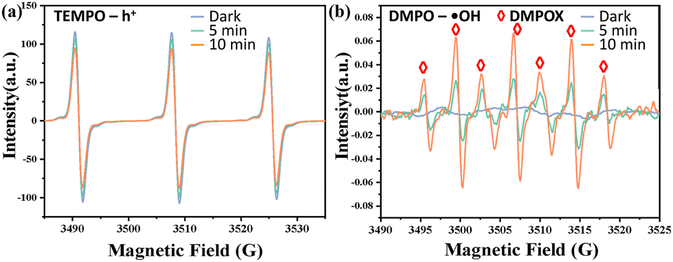 | ||
| Fig. 8 ESR spectra of Ag-TIPA for (a) TEMPO-h+; (b) DMPO-˙OH in the dark and under UV-visible light irradiation. | ||
 | ||
| Fig. 9 Mechanism of photocatalytic degradation of pollutants. | ||
2.5. Possible decomposition pathway of CIP and PNP
Based on the optimized structure of PNP and CIP and the calculated electrostatic potential and frontier molecular orbital analysis, Fig. 10a and d illustrate the electrostatic potential distribution of CIP and PNP, respectively, where the blue area represents the electron-rich area with electrophilic characteristics. In contrast, red regions represent the areas that lack electrons and have nucleophilic properties.40 The frontier molecular orbitals of PNP and CIP are shown in Fig. S11a–d,† indicating that the π-bonding orbitals are mainly located in the benzene and hydroxyl rings (PNP) as well as the quinoline ring (CIP).44 According to the theory of frontier orbitals, ˙OH is more likely to attack positions with higher electron density in the frontier orbitals. The Fukui index and Orbital-Weighted Dual Descriptor (OWDD) theory (Tables S5 and S6†) can also predict the most reactive sites susceptible to free radical attacks. The negative values of the OWDD in the blue regions (Fig. 10b and e) suggest a higher susceptibility to free radicals.44 Taking into account the theoretical analysis and LC-MS measurement (Fig. S9†) identification (Table S8†), the degradation pathway of CIP is described below (Fig. 10c). For pathway I, the piperazine ring of CIP (m/z = 322) undergoes cleavage and is oxidized by ˙OH and H2O2 to form two amide derivatives, P1 (m/z = 334) and P2 (m/z = 334). With further oxidation of P1 and P2, the fluorine element is replaced by the hydroxyl group, a decarboxylation reaction occurs, and the CC bond is oxidized and broken by the hydroxyl radical, yielding P3 (m/z = 308) and P4 (m/z = 308). The tertiary amine group adjacent to the carboxyl group in P3 is oxidized and delocalized to form P5 (m/z = 225). The secondary amine group adjacent to the hydroxyl group and the tertiary amine group adjacent to the carboxyl group are oxidized and delocalized in P4. The benzyl ring reacts electrophilically with ˙OH, and the carboxylic acid group undergoes reduction to an aldehyde group, forming P6 (m/z = 155). In pathway II, the piperazine ring is completely destroyed and converted to the product P8 (m/z = 262), where the fluorine element is replaced by the hydroxyl group and ˙OH attacks the quinoline ring to produce P9 (m/z = 199). In pathway III, the CIP molecule undergoes decarboxylation, and the double bond is oxidized and the ring is opened under the oxidation of ˙OH and H2O2 to produce P10 (m/z = 308). As the aldehyde group on the amide group on P10 is oxidized to a carboxyl group, it is removed to generate P11 (m/z = 298). Piperazine is oxidatively removed to give P12 (m/z = 228), which undergoes decarboxylative oxidation to generate P13 (m/z = 101). Ultimately, these products are mineralized into small molecules, CO2 and H2O.45–49
 | ||
| Fig. 10 Minimum and maximum electrostatic potential (ESP) values for (a) CIP and (d) PNP. OWDD (Δƒw) isosurface (value = 0.001) of (b) CIP and (e) PNP, blue/green (positive/negative values) represents electrophilic/nucleophilic attack susceptibility. The proposed scheme degradation pathways for (c) CIP and (f) PNP. | ||
Similarly, based on the theoretical analysis and LC-MS identification, a degradation pathway for PNP in the photocatalytic system is proposed (Fig. 10f). Additionally, possible intermediates are identified using mass spectra (Table S9†). Under light conditions, nitrophenol is oxidized to phenoxy radicals. The phenoxy radical then undergoes electrophilic substitution and rearrangement reactions with hydroxyl radicals. The oxygen radical binds to PNP, causing the release of OH− and NO2− from the benzene ring, forming part of the phenoxy radical as well as hydroxyl and nitro groups, resulting in intermediates such as nitrobenzene and p-phenol. As the reaction progresses, the radicals continue to oxidize p-nitrophenol and the intermediates, eventually forming compounds such as benzoquinone. Subsequently, the benzene ring is rapidly opened, generating products like trans-(cis-) butanediol acid, oxalic acid, and formic acid, which are ultimately mineralized into CO2 and H2O.
3. Experimental section
Details of the chemical reagents and characterization techniques used in this study are provided in the ESI.†3.1. Synthesis of {[Ag9(TIPA)6](NO3)9·12H2O}n (Ag-TIPA)
AgNO3 (0.0169 g, 0.1 mmol), tris(4-imidazolyl phenyl)amine (TIPA) (0.022 g, 0.05 mmol), 1 mL of N,N-dimethylformamide (DMA), 3 mL of isopropanol, and 20 μL of HNO3 (6 mol L−1) were added to a high-temperature-resistant glass vial. The mixture was placed into a stainless-steel high-pressure reactor with a PTFE liner and screw cap. The reaction was performed in an oven and the reaction temperature gradually increased to 95 °C and this temperature was maintained for 72 h, then naturally cooled to room temperature, filtered, washed, and dried at room temperature to obtain the black lumpy compound Ag-TIPA. FTIR (KBr, cm−1): 3441(m), 3126(m), 1637(m), 1516(s), 1316(s), 1128(m), 1062(s), 962(m), 835(s), and 654(m) (Fig. S5†).3.2. Photocatalytic experimental section
| H2O2 + 2Ce(SO4)2 = Ce2(SO4)3 + H2SO4 + O2 |
The quantitative calculation of H2O2 was determined by measuring the absorption reduction values of UV-vis spectra between 200 and 600 nm.
3.3. Computational details
To analyze the electron cloud distribution of crystalline Ag-TIPA, the Vienna ab initio Simulation Package (VASP)50 was utilized to perform the periodic density functional calculations. A Γ-centered 1 × 1 × 1 Monkhorst–Pack k-point mesh was employed. The convergence threshold for the self-consistent field iteration was set to 10−4 eV, the cutoff energy was 400 eV, and the optimization termination was found to occur when the force acting on each atom was smaller than 0.05 eV Å−1. The optimized periodic structure includes 3 metal Ag atoms, 42 N, 162 C, and 126 H. By completely relaxing the lattice constant, the periodic experimental structure of Ag-TIPA was optimized. The valence and conduction bands of crystalline Ag-TIPA were visualized using VESTA.A cluster model of representative Ag-TIPA was intercepted using an optimized periodic structure containing three metal Ag ions and one TIPA organic ligand. For the Ag-TIPA and TIPA cluster models, the ground state and excited state were calculated using the B3LYP/6-31g51 level, the metal ions were performed using the Stuttgart–Dresden–Dunning (SDD)52 pseudopotential. The restriction optimization was used, and all non-H atomic coordinates were frozen. All cluster structure calculations were done using Gaussian16,53 wavefunction analysis was performed in Multiwfn,54 and molecular frontier orbitals, electrostatic potentials, etc., were visualized using VMD.55
4. Conclusions
In summary, a novel Ag-TIPA two-folded interpenetrated porous coordination polymer was successfully prepared by a solvothermal reaction and its single structure was determined while the chemical state and composition were characterized by XPS. Such a Ag-TIPA coordination polymer exhibited excellent photocatalytic degradation performance for CIP and PNP under UV-visible light irradiation due to the metal–ligand charge transfer promoting the efficient separation of photogenerated electron–hole carriers. Additionally, such Ag-TIPA also indicated high reusability owing to the high stability of the crystal structure in different acidic, neutral and alkaline environments and even in the presence of various sodium salts. In addition, dosage/pollutant concentration/pH/sodium salt effects for the influence of photodegradation of CIP and PNP were investigated in detail. Finally, theoretical calculation and trapping experiment as well as the investigation of electrochemical properties further reveal the intrinsic features of Ag-TIPA and active species under UV-visible light irradiation for CIP and PNP degradation in comparison with the single organic ligand TIPA. A metal–ligand charge transfer mechanism is proposed and the corresponding photodegradation products of CIP and PNP were identified. This work provides a potential strategy for exploring the application of transition metal coordination polymers in photocatalysis, especially in the photodegradation of contaminants, antibiotics and environmental remediation.Author contributions
Zhihu Ma designed and performed experiments and wrote the original draft; Xiaoming Song used software to complete experimental theoretical calculations; Zhaoyu Li helped with the experiment and carried out formal analysis; Yixia Ren directed the conceptualization of this project, provided resources and financial support, and supervised all experimental work; Jijiang Wang provided the methodology and managed the project; Yucang Liang conceptualized and supervised this project and reviewed, revised and edited this manuscript from the first and final version. All authors have read and agreed to the published version of the manuscript.Data availability
CCDC 2294662 contains the supplementary crystallographic data for the coordination polymer Ag-TIPA discussed in this paper.†Conflicts of interest
The authors declare that there is no conflict of interest regarding the publication of this paper.Acknowledgements
This work was supported by the National Natural Science Foundation of China (No. 22063010), the Youth Innovation Team of Shaanxi Universities and the National Undergraduate Training Programs of Innovation and Entrepreneurship (No. 202310719051).References
- C. Zhao, Y. Li, H. Chu, X. Pan, L. Ling, P. Wang, H. Fu, C.-C. Wang and Z. Wang, J. Hazard. Mater., 2021, 419, 126466 CrossRef CAS PubMed.
- S. Kumar, R. D. Kaushik and L. P. Purohit, Sep. Purif. Technol., 2021, 275, 119219 CrossRef CAS.
- X. Di, F. Guo, Z. Zhu, Z. Xu, Z. Qian and Q. Zhang, RSC Adv., 2019, 9, 41209–41217 RSC.
- S. Kumar, R. D. Kaushik and L. P. Purohit, J. Mol. Liq., 2021, 327, 114814 CrossRef CAS.
- M. Preeyanghaa, E. S. Erakulan, R. Thapa, M. Ashokkumar and B. Neppolian, Chem. Eng. J., 2023, 452, 139437 CrossRef CAS.
- C. Gao, J. Wang, H. Xu and Y. Xiong, Chem. Soc. Rev., 2017, 46, 2799–2823 RSC.
- T. Y. Ma, S. Dai, M. Jaroniec and S. Z. Qiao, J. Am. Chem. Soc., 2014, 136, 13925–13931 CrossRef CAS PubMed.
- D. H. Busch, Chem. Rev., 1993, 93, 847–860 CrossRef CAS.
- W. Liu, Y. Chen, H. Qi, L. Zhang, W. Yan, X. Liu, X. Yang, S. Miao, W. Wang, C. Liu, A. Wang, J. Li and T. Zhang, Angew. Chem., Int. Ed., 2018, 57, 7071–7075 CrossRef CAS PubMed.
- M. Mateen, W.-C. Cheong, C. Zheng, S. H. Talib, J. Zhang, X. Zhang, S. Liu, C. Chen and Y. Li, Chem. Eng. J., 2023, 451, 138305 CrossRef CAS.
- Y. Liu, Z. Liu, D. Huang, M. Cheng, G. Zeng, C. Lai, C. Zhang, C. Zhou, W. Wang, D. Jiang, H. Wang and B. Shao, Coord. Chem. Rev., 2019, 388, 63–78 CrossRef CAS.
- S. Berardi, S. Drouet, L. Francàs, C. Gimbert-Suriñach, M. Guttentag, C. Richmond, T. Stoll and A. Llobet, Chem. Soc. Rev., 2014, 43, 7501–7519 RSC.
- S. Wang, C. Shen, Y. Xu, Y. Zhong, C. Wang, S. Yang and G. Wang, ChemSusChem, 2019, 12, 4221–4228 CrossRef CAS PubMed.
- L. Xia, W. Zhou, Y. Xu, Z. Xia, X. Wang, Q. Yang, G. Xie, S. Chen and S. Gao, Chem. Eng. J., 2023, 451, 138747 CrossRef CAS.
- X.-P. Wu, L. Gagliardi and D. G. Truhlar, J. Am. Chem. Soc., 2018, 140, 7904–7912 CrossRef CAS PubMed.
- S.-D. Su, Y.-H. Wen, X.-T. Wu and T.-L. Sheng, Dalton Trans., 2022, 51, 10047–10054 RSC.
- X.-H. Jiang, L.-S. Zhang, H.-Y. Liu, D.-S. Wu, F.-Y. Wu, L. Tian, L.-L. Liu, J.-P. Zou, S.-L. Luo and B.-B. Chen, Angew. Chem., Int. Ed., 2020, 59, 23112–23116 CrossRef CAS PubMed.
- Y. Chen, X. Ren, X. Wang, Z. Tian, X. Yang, J. Lu, H. Bai, T. Jiao, H. Huang and J. Hu, J. Hydrogen Energy, 2022, 47, 250–263 CrossRef CAS.
- Y. Wang, G. Hong, Y. Zhang, Y. Liu, W. Cen, L. Wang and Z. Wu, Angew. Chem., Int. Ed., 2023, 62, e202310525 CrossRef CAS PubMed.
- K. Huang, C. Li, Y. Zheng, L. Wang, W. Wang and X. Meng, Sep. Purif. Technol., 2022, 283, 120194 CrossRef CAS.
- P. Ristić, N. Filipović, V. Blagojević, J. Ćirković, B. B. Holló, V. R. Đokić, M. Donnard, M. Gulea, I. Marjanović, O. R. Klisuriće and T. R. Todorović, CrystEngComm, 2021, 23, 4799–4815 RSC.
- J.-F. Wang, S.-Y. Liu, C.-Y. Liu, Z.-G. Ren and J.-P. Lang, Dalton Trans., 2016, 45, 9294–9306 RSC.
- L.-Y. Xu, W. Yang, C.-F. Liu, Z.-J. Ren and J.-P. Lang, CrystEngComm, 2018, 20, 4049–4057 RSC.
- C.-F. Liu, C.-Y. Liu, Z.-G. Ren and J.-P. Lang, Eur. J. Inorg. Chem., 2019, 1816–1824 CrossRef CAS.
- H. Fu, Y. Jiang, F. Wang and J. Zhang, Nanomaterials, 2021, 11, 2791 CrossRef CAS PubMed.
- F. Zhang, Y.-H. Li, M.-Y. Qi, Z.-R. Tang and Y.-J. Xu, Appl. Catal., B, 2020, 268, 118380 CrossRef CAS.
- F. Zhao, X. Li, T. Xiong, M. Zuo, L. Luo, P. Qin, M. Lei, Y. Liang, X. Gong, D. Zou and Z. Wu, Sep. Purif. Technol., 2023, 314, 123533 CrossRef CAS.
- S. Zhang, Z. Mo, J. Wang, H. Liu, P. Liu, D. Hu, T. Tan and C. Wang, Electrochim. Acta, 2021, 390, 138831 CrossRef CAS.
- H. Feng, C. Zhang, Z. Liu, J. Sang, S. Xue and P. K. Chu, Chem. Eng. J., 2022, 434, 134650 CrossRef CAS.
- M. Pejman, M. D. Firouzjaei, S. A. Aktij, P. Das, E. Zolghadr, H. Jafarian, A. A. Shamsabadi, M. Elliott, M. Sadrzadeh, M. Sangermano, A. Rahimpour and A. Tiraferri, ACS Appl. Mater. Interfaces, 2020, 12, 36287–36300 CrossRef CAS PubMed.
- M. Xu, C. Sun, X. Zhao, H. Jiang, H. Wang and P. Huo, Appl. Surf. Sci., 2022, 576, 151792 CrossRef CAS.
- D. Kanakaraju, J. Kockler, C. A. Motti, B. D. Glass and M. Oelgemöller, Appl. Catal., B, 2015, 166–167, 45–55 CrossRef CAS.
- W. Xing, W. Tu, Z. Han, Y. Hu, Q. Meng and G. Chen, ACS Energy Lett., 2018, 3, 514–519 CrossRef CAS.
- M. Gao, W. Li, X. Su, Z. Li, X. Ding, X. Du, Y. Ren, H. Zhang, J. Feng and T. Wei, Sep. Purif. Technol., 2023, 313, 123447 CrossRef CAS.
- Y. Cui, G. Zhang, Z. Lin and X. Wang, Appl. Catal., B, 2016, 181, 413–419 CrossRef CAS.
- S. Guo, Z. Deng, M. Li, B. Jiang, C. Tian, Q. Pan and H. Fu, Angew. Chem., Int. Ed., 2016, 55, 1830–1834 CrossRef CAS PubMed.
- D. Roy, S. Neogi and S. De, Chem. Eng. J., 2022, 428, 131028 CrossRef CAS.
- Y. Li, R. Jin, Y. Xing, J. Li, S. Song, X. Liu, M. Li and R. Jin, Adv. Energy Mater., 2016, 6, 1601273 CrossRef.
- D. Yu, L. Li, M. Wu and J. C. Crittenden, Appl. Catal., B, 2019, 251, 66–75 CrossRef CAS.
- W. Liu, Y. Li, F. Liu, W. Jiang, D. Zhang and J. Liang, Water Res., 2019, 151, 8–19 CrossRef CAS PubMed.
- J. Yuan, H. Li, G. Wang, C. Zhang, Y. Wang, L. Yang, M. Li and J. Lu, Appl. Catal., B, 2022, 303, 120892 CrossRef CAS.
- G. Zhang, X. Yang, Z. Wu, W. D. Wu, X. Wang, X. D. Chen and S.-P. Sun, ACS ES&T Water, 2022, 2, 1234–1246 Search PubMed.
- H. Huang, S. Tu, C. Zeng, T. Zhang, A. H. Reshak and Y. Zhang, Angew. Chem., Int. Ed., 2017, 56, 11860–11864 CrossRef CAS PubMed.
- J. Zhu, H. Wang, A. Duan and Y. Wang, J. Hazard. Mater., 2023, 446, 130676 CrossRef CAS PubMed.
- X. Wang, Z. Liu, X. Yan, T. Lu, H. Wang, W. Xiong and M. Zhao, Phys. Chem. Chem. Phys., 2022, 24, 7466–7473 RSC.
- K. Yun, K. Saravanakumar, G. Jagan, Y. Yea, Y. Yoon and C. M. Park, Chem. Eng. J., 2023, 468, 143491 CrossRef CAS.
- C. Hu, M. Chen, L. Wang, Y. Ding, Q. Li, X. Li and J. Deng, Chemosphere, 2023, 336, 139202 CrossRef CAS PubMed.
- X. Qian, Y. Ma, M. Arif, J. Xia, G. He and H. Chen, Sep. Purif. Technol., 2023, 316, 123794 CrossRef CAS.
- J. Shang, T. Zhang, X. Li, Y. Luo, D. Feng and X. Cheng, Sep. Purif. Technol., 2023, 311, 123342 CrossRef CAS.
- G. Kresse and J. Furthmüller, Phys. Rev. B: Condens. Matter Mater. Phys., 1996, 54, 11169–11186 CrossRef CAS PubMed.
- R. Pino-Rios, D. Inostroza, G. Cárdenas-Jirón and W. Tiznado, J. Phys. Chem. A, 2019, 123, 10556–10562 CrossRef CAS PubMed.
- D. Andrae, U. Häußermann, M. Dolg, H. Stoll and H. Preuß, Theor. Chim. Acta, 1990, 77, 123–141 CrossRef CAS.
- Z. He, Y. Wu, N. Li, H. Lai, B. Liu and T. Jin, J. Alloys Compd., 2023, 960, 170335 CrossRef CAS.
- T. Lu and F. Chen, J. Comput. Chem., 2012, 33, 580–592 CrossRef CAS PubMed.
- W. Humphrey, A. Dalke and K. Schulten, J. Mol. Graphics, 1996, 14, 33–38 CrossRef CAS PubMed.
Footnote |
| † Electronic supplementary information (ESI) available. CCDC 2294662. For ESI and crystallographic data in CIF or other electronic format see DOI: https://doi.org/10.1039/d3dt03727d |
| This journal is © The Royal Society of Chemistry 2024 |