
 Open Access Article
 This Open Access Article is licensed under a Creative Commons Attribution-Non Commercial 3.0 Unported Licence
Enhancing coking resistance of nickel-based catalysts for dry reforming of methane via nitric oxide abatement: a support study†
Beatrice
Senoner
 *a,
Andrea
Osti
a and
Antonella
Glisenti
ab
*a,
Andrea
Osti
a and
Antonella
Glisenti
ab
aDipartimento di Scienze Chimiche, Università degli Studi di Padova, Via F. Marzolo, 1, 35131, Padova, Italy. E-mail: beatrice.senoner@phd.unipd.it
bICMATE – CNR c/o Dipartimento, Italy
First published on 16th October 2024
Abstract
Coking poses a significant challenge to the longevity and efficacy of catalysts in dry reforming of methane (DRM), particularly for nickel-based catalysts, which are widely used for their affordability and high catalytic activity. This study explores a recent approach integrating DRM with NO reduction to address coking-related deactivation, aiming to gasify carbon deposits and reduce NO simultaneously. Therefore, herein, NO conversion is achieved using the carbon undesired by-product of the DRM reaction, avoiding the use of valuable resources for NO conversion (such as NH3), via an approach “from waste to value” that enhances the sustainability of the process. Four nickel-impregnated oxide supports (γ-Al2O3, MgAl2O4 coated γ-Al2O3, CaZrO3, and LaFeO3) were compared to understand the key properties of catalyst design. The best performances were obtained for supports with a high surface area and high interaction with metal particles (95% reactant conversion for Ni/γ-Al2O3) as they allowed stable activity and protection from NO oxidation. Supports with a lower surface area suffered from coke blockage of active sites, whereas no protection from oxidation led to complete deactivation of the active phase. The LaFeO3 support stood out for its ability to protect Ni from NO oxidation by reducing NO. Overall, this study showed the importance of balancing NO oxidative power and coking issues, emphasizing the relevance of catalyst design in both protecting Ni from NO oxidation and avoiding coke blockage of the active sites via high surface area supports.
1. Introduction
Dry reforming of methane (DRM) is a dream reaction that allows the conversion of two pollutants/greenhouse gases into a highly energetic gas mixture: syngas. One of the most commonly used active metals is nickel, which provides comparable activity to noble metals, without the heavy cost and availability problems of the latter.1,2 However, nickel catalysts are sensitive to deactivation by coking and sintering; thus, to develop catalysts with industrial applicability, extending their lifetime is one of the key requirements.3–5 In this project, catalysts were studied for a process in which dry reforming of methane and nitric oxide reduction reactions are involved. The reactions involved in the process are presented below:| CH4 (g) + CO2 (g) → 2CO (g) + 2H2 (g) | (1) |
| CO2 (g) + H2 (g) → CO (g) + H2O (g) | (2) |
| CH4 (g) → 2C (s) + 2H2 (g) | (3) |
| C (s) + CO2 (g) → 2CO (g) | (4) |
 | (5) |
In this work, we prepared and investigated the activity in the DRM–NO reduction process of four supported catalysts, with the support being the oxides described above, and the active metal being Ni. The 13 wt% Ni impregnation has been chosen as a value inside the standard percentage range of 10–15% for industrial application of DRM, as reported in the literature.29–31 The physical and chemical properties of the catalysts were analyzed by N2-physisorption, H2-temperature programmed reduction (H2-TPR), H2-pulsed chemisorption, X-ray diffraction (XRD), XPS (X-ray photoelectron spectroscopy), and SEM-EDX (scanning electron microscopy-energy dispersive X-ray) to gain insight into the catalyst's properties. With the analysis above, the relationship between catalytic activity and structure was established. Furthermore, O2-temperature programmed oxidation (O2-TPO), XRD and XPS techniques were applied to post-reaction catalysts to examine the change in the catalysts induced by the process.
2. Experimental
2.1. Synthesis of catalysts
Catalysts were prepared via wet-chemical environmentally friendly synthesis using water as solvent. In the first step, the support was obtained (around 3 g); then, nickel oxide nanoparticles were deposited in the second step. To obtain the active form of the catalyst, a 5% H2 treatment was needed to reduce nickel oxide and obtain metallic nickel.Supports were obtained with a yield of around 80–90%.
2.2. Characterization of catalysts
All catalysts were characterized using the following techniques. The chemical composition and crystalline phases of the samples were studied via X-ray diffraction (XRD) using a Bruker D8 Advance diffractometer with Bragg–Brentano geometry using Cu Kα radiation (40 kV, 40 mA, λ = 0.154 nm). Phase structures were assigned based on search-match software utilizing the COD-Inorg REV189751 database. X-ray photoelectron spectroscopy (XPS) analysis was performed to study the composition and phases of the surface of the samples via a Thermo Scientific ESCALAB QXi spectrometer, employing a monochromatized Al Kα source (hν = 1486.68 eV) and a charge compensation gun. Survey spectra were acquired at pass energy 100 eV, resolution 0.5 eV per step, and dwell time 25 ms per step. Elemental quantification was carried out by the integration of photopeaks after Shirley-type background subtraction,34 and the atomic percentage was evaluated using Thermo Scientific sensitivity factors.35 For the correct interpretation of XPS spectra, the NIST XPS database was employed (version 4.1).36 Energy-dispersive X-ray analysis (EDX) was obtained to gain information about the composition of the samples with a Zeiss SUPRA 40 V P microscope at 20 kV electron acceleration voltage, probing a large area of the sample (rectangle of hundreds of μm each side). N2 physisorption analysis was conducted using a Micromeritics ASAP2020 analyser to gain information about the specific surface area (SSA) and porosity of the samples via BET analysis. Around 50 mg of the sample was degassed at 300 °C for 6 h under reduced pressure (around 0.013 mbar) before adsorption occurred. The analysis was conducted at −196 °C, collecting 80 points between p/p0 = 0.002 and p/p0 = 1. H2-temperature programmed reduction (H2-TPR, AutoChem II 2920) experiments were performed to determine the sample reducibility. Experiments were carried out in a U-shaped quartz reactor using 50 mg of sample and heating from RT to 900 °C or 600 °C at 10 °C min−1 under a constant flow of H2 5% in Ar (50 ml min−1). The same instrument was used to determine Ni dispersion via H2-pulsed chemisorption. After reduction, the catalysts were cooled to 40 °C in the same environment, and H2 was repeatedly pulsed 20 times at the same temperature. Finally, SEM-EDX maps were obtained with JEOL JEM-F200 TEM (200 kV).2.3. Catalytic tests
Dry reforming of methane coupled with nitric oxide reduction was performed on the four samples in a quartz tube fix bed reactor (ID 6 mm) loaded with about 50 mg of catalyst sandwiched between two quartz wools, with a thermocouple mounted upstream of the bed. Two reaction mixtures were studied, composed of 5 CH4, 5 CO2, 1% NO and 25% CH4, 25% CO2, and 1% NO, using Ar as a balance for a total flow rate of 100 mL min−1 and a WHSV of about 120 L g−1 h−1. Before the catalytic experiments, a reductive treatment was performed to obtain the active form of the catalysts using a 5% H2 flow in Ar and increasing the temperature to 900 ° C for Al2O3-based samples and 600 °C for perovskite samples, as suggested by TPR measurements, with a ramp of 10 °C min−1. Then, catalytic measurements were conducted at 750 °C. The reaction mixture was analyzed using an on-line Agilent Technologies 7890A gas-chromatograph, equipped with a TCD detector. A condenser to trap the generated water was employed between the reactor and GC.2.4. Characterization of post-reaction catalysts
Catalysts were evaluated after the process with XRD and XPS analyses to appreciate the changes after the process. Raman spectroscopy was used to study the coke deposition on a Thermo Scientific DXR Raman Microscope, with the excitation line λ = 532 nm. O2-TPO (temperature-programmed oxidation) experiments were conducted to examine the quantity and type of coke deposited onto the catalyst during the catalytic tests. Around 20 mg of post-reaction catalysts were loaded between two quartz wools into a quartz tube reactor coupled with a thermocouple for the catalytic tests. Then, 25% air in Ar (5% O2), for a total flow rate of 100 ml min−1 and a WHSV of about 240 L g−1 h−1, was used to carry out the TPO measurements, while the temperature increased from room temperature to 900 °C (ramp of 2 °C min−1). The reaction mixture was analyzed with an online Agilent Technologies 7890A gas chromatograph (GC), equipped with a TCD detector; a condenser was used to trap the generated water between the reactor and GC.3. Results and discussion
3.1. Catalyst characterization: XRD, N2 physisorption, H2-TPR and XPS techniques
 | ||
| Fig. 1 XRD pattern of Al2O3 (a), MgAl2O4–Al2O3 (b), CaZrO3 (c) and LaFeO3 (d) synthetized supports after calcination and of the respective 13 wt% Ni impregnated catalysts. | ||
The four supports showed the correct synthesis of the supports, with only CaZrO3 having traces of ZrO2 impurities, due to unreacted ZrO2 (Fig. 1(c)).37 After impregnation, the catalysts showed the correct deposition of NiO. Moreover, in the alumina-based samples (Fig. 1(a) and (b)), the formation of NiAl2O4 spinel is possible due to nickel entering the alumina structure, as reported in the literature. However, its reflections could not be clearly detected as they are partially hindered by the alumina. For the NiO/MgAl2O4–Al2O3 sample (Fig. 1(b)), an additional contribution to the broad reflection at 2θ = 66° could be observed on the left side of the reflection after NiO impregnation, which could be because the NiAl2O4 phase overlapped with the Al2O3 and MgAl2O4 phases. Therefore, XPS analysis was performed to gain more information (subsubsection 3.1.4.).
| Sample | BET surface area (m2 g−1) |
|---|---|
| NiO/Al2O3 | 105 |
| NiO/MgAl2O4 | 62 |
| NiO/CaZrO3 | 3 |
| NiO/LaFeO3 | 6 |
Samples show different values of surface area based on the properties of the material and synthesis conditions (Table 1). As NiO deposition was done using the same synthesis conditions (13 wt%, 650 °C, 6 h), the catalyst differences between the supports caused a difference in the values of the surface area. Commercial Al2O3 support showed a higher surface area (104.7 m2 g−1) that diminished to approximately half its value when coated with MgAl2O4 (61.5 m2 g−1), which required an additional calcination treatment at 900 °C, with consequent sintering. Perovskite samples showed lower values of surface area, as expected for the intrinsic characteristics of these oxides.25 Moreover, CaZrO3 perovskite needed a high calcination temperature (1400 °C) to obtain low amounts of ZrO2 impurities, so its surface area is the lowest (3.0 m2 g−1) due to sintering of the support. LaFeO3 perovskite, however, was obtained as a pure crystalline phase using a calcination temperature of 900 °C, which allowed us to obtain higher surface areas (6.4 m2 g−1, double with respect to CaZrO3). Finally, the desorption isotherms were allowed to conduct a BJH analysis to determine the pore size distribution (Fig. S1 in ESI†). BJH (Barrett, Joyner, and Halenda) analysis showed pores mainly distributed for NiO/Al2O3 and NiO/MgAl2O4–Al2O3 in the range of 3–9 nm, which accounts for the mesoporosity of alumina-based samples. Perovskite samples, however, have larger and fewer pores than alumina-based samples and, overall, less porosity. The NiO/LaFeO3 catalyst has a pore size distribution mainly after 10 nm of pore width, and its pore volume doubles that of NiO/CaZrO3, in accordance with their surface area values.
 | ||
| Fig. 2 H2-TPR experiment on NiO/Al2O3 (a), NiO/MgAl2O4–Al2O3 (b), NiO/CaZrO3 (c) and NiO/LaFeO3 (d, black) and LaFeO3 support (d, red) (from room temperature to 900 °C) (H2 quantification in ESI†). | ||
 | ||
| Fig. 3 Detailed XPS spectra of Fe 2p photopeak for Ni/LaFeO3 catalyst (after H2-TPR from room temperature to 600 °C). | ||
NiO/γ-Al2O3 exhibited 2 reduction peaks at 400 °C and 700 °C (Fig. 2(a)). The first reduction peak is attributed to NiO weakly interacting with γ-Al2O3, while the second peak at higher temperatures is attributed to a strong interaction between nickel and alumina.39 The latter has a shoulder above 700 °C probably due to NiAl2O4 spinel, as reported in the literature.19,40,41 Therefore, γ-Al2O3 is prone to the formation of the nickel spinel, as at high calcination temperatures, nickel ions gain sufficient energy to integrate into the alumina lattice to produce the spinel.19
For NiO/MgAl2O4–Al2O3 (Fig. 2(b)), a first peak was detected at around 400 °C due to surface NiO weakly interacting with MgAl2O4 for the previous catalyst. The second and third peaks were detected at 700 °C and 800 °C, respectively. The second peak is broad and has a left shoulder above 600 °C and a right shoulder around 746 °C, suggesting different strengths of interaction. High reduction temperatures are usually attributed to spinel strongly interacting with nickel particles, so most probably at 800 °C, nickel enters the magnesium aluminum spinel to form the nickel aluminum spinel.42,43 To investigate this possibility, the XRD of the reduced sample was analyzed, as shown in Fig. 3(b). Perovskite samples showed reducibility at low temperatures (400 °C), corresponding to NiO weakly interacting with the perovskite support (Fig. 2(c) and (d)). In NiO/LaFeO3 (Fig. 2(d)), an additional peak was observed from 750 °C, which accounts for perovskite reduction, as confirmed by the literature and XRD analysis (Fig. 3(d)).44 To verify whether LaFeO3 reduction occurred in correspondence with NiO reduction, an additional H2-TPR experiment was performed on the perovskite support (Fig. 2(d)); this allowed us to verify the reduction of perovskite at 750 °C and to appreciate the reduction process at 400–600 °C, giving iron sub-stoichiometric perovskites, as reported in the literature.45
XRD patterns of the reduced catalysts were collected and are shown in ESI† (Fig. S3). Complete reduction of NiO to Ni0 was observed for all catalysts. For alumina-based catalysts, however, NiII present as NiAl2O4 could be reduced to Ni0. No information could be retrieved about the presence or reduction of NiAl2O4 spinel in NiO/Al2O3 (Fig. S3(a)†) due to the overlap of its peak with Ni, NiO and Al2O3 peaks; therefore, further analysis was performed (see XPS analysis, subsubsection 3.1.4.). However, the XRD pattern of the post-calcination and post-reduction NiO/MgAl2O4–Al2O3 catalyst (Fig. S3(b)†) showed differences in the peak at 2θ = 66°. The broad peak is symmetric in NiO/MgAl2O4–Al2O3, with contributions of MgAl2O4, Al2O3 and possibly NiAl2O4 reflections. When the catalyst is reduced, a significant change in the shape of the peak can be observed, which accounts for the loss of a contribution to its left shoulder. At this 2θ, the latter contribution is most probably due to the presence of the spinel, which can be reduced (totally or partially) during reductive treatment to gain the active metallic phase of the catalyst. The spinel peaks overlap with MgAl2O4 and Al2O3 peaks; therefore, XPS analysis was performed to verify this hypothesis (subsubsection 3.1.4.). Besides, XRD analysis shows a complete reduction of crystalline NiO to Ni. XRD of post-reduction perovskite samples showed the complete reduction of NiO as in the previous samples (Fig. S3(c) and (d)†). NiO/LaFeO3 showed La2O3 and metallic Fe formation due to perovskite reduction, as expected from the literature (Fig. S3(d)†).45
Moreover, an additional H2-TPR treatment from room temperature to 600 °C of NiO/LaFeO3 was done to verify the complete reduction of NiO. XRD analysis allowed us to observe the complete reduction of NiO to its active form (Fig. S3(e)†), while the presence of Fe0 given by the formation of iron sub-stoichiometric perovskites was confirmed by XPS analysis, where Fe0 presence is evidenced by a contribution at 707 eV to LaFeO3 2p3/2 (Fig. 3).36,46
H2-pulsed chemisorption was conducted on all catalysts to determine nickel dispersion after reduction, using Bartholomew approximation.47 Ni dispersion (reported in ESI†) was approximately 0.3% for all samples except for Ni/CaZrO3, for which the value of 1.66% could not be rationalized with the other characterization results (H2-TPR, XRD, XPS and TEM data), thereby implying a mismatch with the reference model assumptions (such as having spherical particles, having 1 hydrogen atom adsorbed by each nickel atom and having only hydrogen chemisorption due to the nickel present in the samples). The dispersion was correlated with the strength of the interaction of Ni particles with the support (see H2-TPR above). For Ni/MgAl2O4–Al2O3 characterized by the strongest interaction with Ni, a higher dispersion value was found (0.36%), while Ni/LaFeO3 had the lowest dispersion (0.26%) due to the low interaction of Ni with the support. Ni dispersion was further analyzed using TEM (Fig. S4†), which showed for alumina-based samples similar Ni distribution, with particle dimensions in the range of 15–20 nm. Perovskite samples showed less dispersed Ni due to their low surface area (see Table 1). On Ni/CaZrO3, a very large conglomerate and inhomogeneous Ni distribution for Ni/LaFeO3, an intricate pattern was found, which revealed the presence of Ni particles with dimensions around 8–16 nm at the edges of the fragments, while at the core of the fragments, conglomeration of the latter nanoparticles was expected due to the lower interaction with the support and the lowest Ni dispersion (see above). Therefore, TEM allowed us to conclude that while alumina-based catalysts had a good distribution of Ni particles, perovskite's low area caused the formation of agglomerations of Ni nanoparticles, especially for Ni/CaZrO3.
 | ||
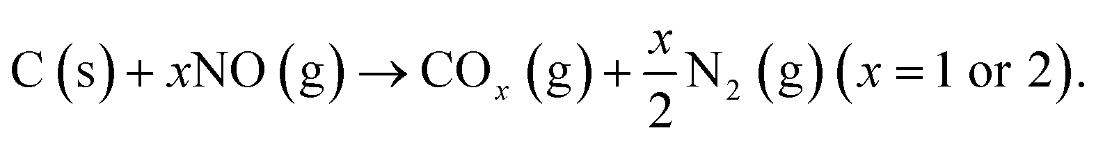
| Fig. 4 Detailed XPS spectra of Ni 2p photopeak for Ni/Al2O3 (a) and Ni/MgAl2O4–Al2O3 (b) samples (post H2-TPR) and reference spectra of Ni, Ni(OH)2 and NiO taken from the literature (c).48 Ni 2p fit is available in ESI.† | ||
From the Ni 2p photopeak, it is possible to observe the presence of two contributions: Ni0 at 852.9 eV, as expected after the reduction treatment, and a NiII species contribution at 855.3 eV. The latter species was attributed to nickel hydroxide, as expected for impregnated nickel nanoparticles exposed to air after reduction.49 The presence of this species is probably due to metallic nickel that is superficially oxidized when placed in contact with air; this explains why Ni(OH)2 is visible in XPS spectra (Fig. 4) and not in XRD measurements (Fig. S3†), as only the most superficial layers of Ni0 are oxidized. However, this phenomenon does not affect the catalytic activity of the samples, as catalysts are reduced and then directly tested for catalytic activity using the same apparatus, thereby avoiding the oxygen-containing atmosphere of the air.
By comparing the Ni photopeak of alumina-based catalysts (Fig. 4(a) and (b)) with the reference peak (Fig. 4(c)), an added contribution can be observed in the spectra. This contribution can be centered around 858.1 eV, and it accounts for the presence of a NiII species different from Ni(OH)2, which is in agreement with what is expected for this element in NiAl2O4 spinel. To verify this hypothesis, Al 2p photopeaks were acquired and revealed the presence of the spinel (Fig. 5(a) and (b)).
 | ||
| Fig. 5 Detailed XPS spectra of Al 2p photopeak for Ni/Al2O3 (a) and Ni/MgAl2O4–Al2O3 (b) catalysts (post H2-TPR) and their fit. | ||
Spinel's contribution can be easily observed in the NiO/Al2O3 sample (Fig. 5(a)) owing to the shoulder at 74.7 eV, which accounts for NiAl2O4 presence in addition to the 74.0 eV peak of Al2O3.50 In NiO/MgAl2O4–Al2O3, a broad peak was detected due to three contributions (Fig. 5(b)): MgAl2O4 on the left shoulder (75.3 eV), Al2O3 on the right side of the peak (74.0 eV) and a last contribution on the left of the peak at 74.7 eV attributed to NiAl2O4 spinel.36,51 To gain more information about the species present in the sample, a Mg 1s photopeak was acquired (Fig. 6).
 | ||
| Fig. 6 Detailed XPS spectra of Mg 1s photopeak for Ni/MgAl2O4–Al2O3 catalyst (post H2-TPR) and its fit. | ||
MgAl2O4 was present at 1305.5 eV, and another contribution at 1303 eV was attributed to Mg0. This species could form due to the entry of Ni into the MgAl2O4 structure, causing the formation of the spinel NiAl2O4 and the reduction of Mg2+ that was in the spinel structure to Mg0. This has been previously observed in the literature for catalysts with high nickel loadings.52
3.2. Catalytic performance: impact of the support
 | ||
| Fig. 7 CO2 and CH4 conversions for 5% CH4, 5% CO2, 1% NO gas mixture for NiO/Al2O3, NiO/MgAl2O4–Al2O3, NiO/CaZrO3 and NiO/LaFeO3 catalysts. | ||
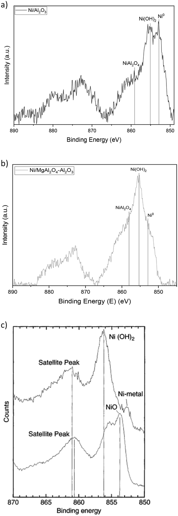
The first tests were conducted with a 5% CH4, 5% CO2, and 1% NO gas mixture (Fig. 7). All catalysts except NiO/LaFeO3 encountered rapid deactivation in the first 400 minutes of the reaction. Alumina-based catalysts showed high initial conversions, which rapidly went from around 80% and 40% for NiO/Al2O3 and NiO/MgAl2O4–Al2O3, respectively, to no catalytic activity after 500 minutes. XRD analysis was performed to understand the cause of deactivation (Fig. 8). No carbon was shown by XRD analysis due to the low concentration of reactants and to the high NO concentration, which enhanced the oxidative properties of the reaction mixture.7 Moreover, from the XRD patterns of the post-reaction catalysts (Fig. 8), it was possible to observe the strong oxidation of Ni from its active metal form to its inactive oxide form. Nickel conversion to NiO is believed to be a reaction that causes fast catalyst deactivation.7 Comparing the activity of the alumina-based catalysts, the NiO/Al2O3 catalyst showed the highest CO2 and CH4 conversions (around 70% in the first 200 minutes of reaction), which decreased by 20% for over 200 minutes, while NiO/MgAl2O4–Al2O3's conversions were lower (around 40%) but remained constant simultaneously. This might be due to the better stability of Ni particles due to their interaction with MgAl2O4–Al2O3 support, as suggested by H2-TPR studies (subsubsection 3.2.3.). Perovskite catalysts were tested, showing different behaviors from each other. Although NiO/CaZrO3 had almost no catalytic activity (maximum conversion of 10% for both reactants), NiO/LaFeO3 showed the highest and most stable activity, with CO2 and CH4 conversions around 90% during all the reaction times. The latter catalyst showed comparable CO2 and CH4 conversions that are influenced by a change in NO behavior, while for the other catalysts, NO reacted with Ni until complete NiO oxidation and catalytic activity were retained throughout all 15 hours. This means that NO must react with either CH4 or another reducing gas produced by dry reforming of methane, such as CO or H2, to ensure complete NO reduction to N2, as was observed during the process. Because NiO/CaZrO3's poor interaction with nickel particles determines its fast deactivation due to NO oxidation, NiO/LaFeO3 was able to protect the particles from NO, and perovskite was able to reduce NO and therefore preserve the nickel particles in their metal form. Overall, LaFeO3 was the best support for these reactant concentrations, providing high catalytic activity (90% CO2 and CH4 conversions) throughout the 900 minutes tested. The XRD pattern of post reaction NiO/LaFeO3 (Fig. 8(d)) showed NiO presence. However, nickel in its active metal form must be present to ensure the high and constant catalytic activity obtained; thus, Ni0 would most probably be present as an amorphous or highly dispersed form in the sample.
 | ||
| Fig. 8 XRD pattern of post-reaction catalytic experiment on NiO/Al2O3 (a), NiO/MgAl2O4–Al2O3 (b), NiO/CaZrO3 (c) and NiO/LaFeO3 (d) catalysts (5% CH4, 5% CO2, and 1% NO gas mixture). | ||
As the first tests showed deactivation problems due to nickel oxidation by NO, further tests were performed to achieve a less oxidative environment using a 25% CH4, 25% CO2, and 1% NO gas mixture, aiming to balance NO oxidative power with a higher concentration of CH4 reactant and CO and H2 produced by DRM reaction (1) (Fig. 9).
 | ||
| Fig. 9 CO2 and CH4 conversions for 25% CH4, 25% CO2, and 1% NO gas mixture for NiO/Al2O3, NiO/MgAl2O4–Al2O3, NiO/CaZrO3 and NiO/LaFeO3 catalysts. | ||
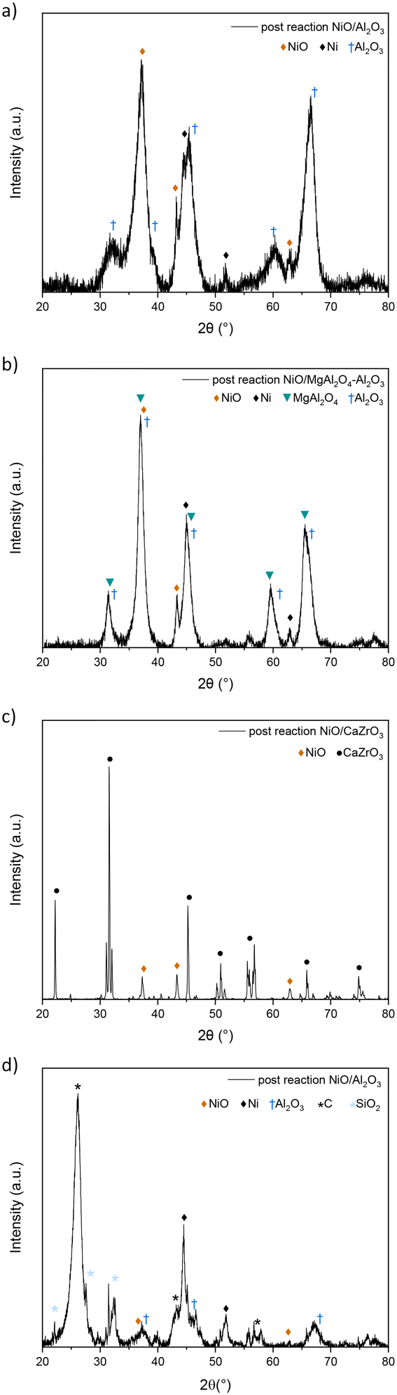
High and stable conversions were obtained for NiO/Al2O3, which were around 93% for CO2 and 94% for CH4. At the beginning of the experiment, high CO2 conversions were immediately achieved for NiO/Al2O3, while CH4 reached its maximum activity after 200 minutes of reaction probably due to the presence of nickel in a non-active form, such as NiAl2O4 or Ni, strongly interacting with the support, as previously observed in H2-TPR studies (subsubsection 3.1.3.). During the reaction, as H2 develops from the DRM reaction (1), nickel can be reduced in its active metal form. CO2 conversions, however, slightly decreased until 200 minutes of reaction, passing from around 96% to 93%; this could be explained by a contribution to CO2 concentrations due to the nitric oxide reaction with coke (reaction (5)), which gives CO2 as a product, therefore causing higher CO2 concentrations in the reaction mixture. The XRD pattern of the spent catalyst (Fig. 10(a)) showed a relevant carbon deposition in the form of graphite. Ni is present in its active metallic form. Little NiO is present in the pattern although it does not cause problems to the catalytic activity, as can be deduced from the stability of the conversions. γ-Al2O3 support was not modified during the reaction; NiAl2O4 spinel was not detected by XRD analysis probably because during the reaction, part of H2 can reduce NiII of NiAl2O4 to its metallic form.53
 | ||
| Fig. 10 XRD pattern of post-reaction experiment on NiO/Al2O3 (a), NiO/MgAl2O4–Al2O3 (b), NiO/CaZrO3 (c) and NiO/LaFeO3 (d) catalysts (25% CH4, 25% CO2, and 1% NO gas mixture). | ||
NiO/MgAl2O4–Al2O3 showed high CO2 and CH4 conversions (97% and around 85% respectively), with CO2 conversion higher than CH4 probably due to the basicity of the support that enhances CO2 adsorption, therefore leading to the reverse water gas shift reaction (2).54,55 CO2 conversions were stable; however, CH4 conversion decreased slightly in 15 hours, decreasing from around 88% to 82%. This might be due to deactivation that occurs during the reaction as a result of sintering and coking, which could diminish the number of active sites in the samples, which affects NiO/MgAl2O4–Al2O3 and not NiO/Al2O3 due to the different surface area values (see Table 1). The XRD pattern (Fig. 10(b)) revealed the presence of graphitic carbon as in the previous sample; nickel was present in its metallic form, and no nickel oxide was detected probably because of the high interaction between the support and Ni particles previously determined by H2-TPR (subsubsection 3.1.3.). No nickel spinel was detected, which was probably reduced by H2 produced in the process as for NiO/Al2O3, while the support remained unchanged for the rest.
NiO/CaZrO3 showed no catalytic activity (Fig. 9), and post-reaction XRD showed complete nickel oxidation (Fig. 10(c)). This is likely due to the perovskite support, with its low interaction with Ni particles, as observed in H2-TPR (subsubsection 3.1.3.), could not protect the Ni particles from NO oxidation, and Ni agglomeration occurred because of the low surface area (see Table 1 and SEM-EDX maps). Therefore, no carbon was deposited during the process, as nickel was deactivated by oxidation before carbon deposition occurred (Fig. 10(c)).
NiO/LaFeO3 sample showed high CO2 conversion (around 91%) at the beginning of the reaction, which then diminished until 83% at the end of the process (Fig. 9). CH4 conversions started at 55% and then decreased to 44% (Fig. 9). For this catalyst, it is interesting to compare the conversions between the 5% CO2, 5% CH4, and 1% NO (Fig. 7) as well as the 25% CO2, 25% CH4, and 1% NO tests (Fig. 9). Comparing the activity recorded in this test and the one with 1/5 of CO2 and CH4 reactant, it appears that the catalyst does not have the same stability of conversions in the range of time as in the previous test. Conversions slowly decreased over time probably owing to the weaker interaction of nickel particles with the perovskite support (see subsubsection 3.1.3.), which caused Ni particles to be more sensitive to sintering and coking during the reaction, leading therefore to a slow deactivation.56 It is also important to remember that perovskite-based catalysts are characterized by low surface area values (1 order of magnitude difference from alumina-based samples (see section 3.1.2.)) that can have an impact on the catalytic behaviour of the sample. In 5% CO2, 5% CH4 and 1% NO tests (Fig. 7), the conversions were constant in the reaction time because no coke was deposited, therefore limiting the deactivation due to coke deposition, and the properties of the supports allowed the particles to be protected from NO oxidation, as observed before.18 Post-reaction XRD (Fig. 10(d)) showed the presence of graphitic carbon and partial nickel oxidation to NiO as in the other samples; the support remained unchanged during the 15 hour process.
Finally, TOF values were calculated for both CO2 and CH4 to compare catalyst reactivity under the two different conditions (see ESI†).57 However, we consider that both CO2 and CH4 are involved in side reactions (see the Introduction). Therefore, CO2 and CH4 conversions employed for TOF calculations contribute owing not only to the dry reforming of methane but also to carbon deposition, its gasification with CO2, and RWGS. TOF values followed the trend of reactant conversions and increased by 1 order of magnitude for 25% CO2/CH4 tests due to the increased quantity of fluxed reactants and the higher conversions obtained owing to the more balanced reducing/oxidative gas mixture.
| Support | Post-reduction C atomic surface composition (at%) | Post-reaction C atomic surface composition (at%) |
|---|---|---|
| Al2O3 | 26.0 | 89.3 |
| MgAl2O4–Al2O3 | 8.6 | 85.9 |
| CaZrO3 | 28.9 | 15.1 |
| LaFeO3 | 31.4 | 82.9 |
As expected, carbon atomic percentage drastically increases after catalysis for all samples except NiO/CaZrO3, which had no catalytic activity (Fig. 9 and 10) and in which the carbon amount decreases presumably as a consequence of thermal treatment. Regarding alumina-based catalysts, post-reaction catalysts have a higher carbon surface composition for acidic supported catalyst NiO/Al2O3 than for basic catalyst NiO/MgAl2O4–Al2O3, as expected for the improved CO2 chemisorption enhancement typical of basic supports.12 Moreover, post-reaction NiO/LaFeO3 shows the lowest concentration of carbon on its surface better than NiO/MgAl2O4–Al2O3; this could be related to its ability to interact with NO molecules and therefore facilitate the NO gasification of coke.28
To better understand the coking phenomena, detailed C1s XPS spectra of the post-reaction catalysts were acquired, as shown in Fig. 11.
 | ||
| Fig. 11 XPS spectra for C 1s of post-reaction samples (25% CH4, 25% CO2, and 1% NO gas mixture) for NiO/Al2O3 (a), NiO/MgAl2O4–Al2O3 (b), NiO/CaZrO3 (c) and NiO/LaFeO3 (d) catalysts. | ||
C1s photopeaks of CaZrO3 showed typical features of adventitious carbon C–C peak at 284.8 eV, and at higher binding energies typical C–O–C (286 eV) and O–C![[double bond, length as m-dash]](https://www.rsc.org/images/entities/char_e001.gif) O (288.5 eV) contributions were observed. Carbonate species were also present on the NiO/MgAl2O4–Al2O3 catalyst, which is consistent with the mentioned hypothesis of enhanced capability of interaction with CO2 and consequent lower coke poisoning. For NiO/Al2O3, NiO/MgAl2O4–Al2O3 and NiO/LaFeO3 catalysts, the peak was centered at 284.5 eV, a typical value for the C–C bond of the graphitic carbon. A tail can be observed around 285–286 eV, which accounts for satellites of C1s.36,58 Moreover, in NiO/MgAl2O4–Al2O3, it is possible to appreciate an additional contribution at around 286 eV due to oxygenating species that are present together with the adventitious carbon peak.59 Therefore, XPS results confirm the presence of graphitic carbon obtained through XRD experiments (Fig. 10).
O (288.5 eV) contributions were observed. Carbonate species were also present on the NiO/MgAl2O4–Al2O3 catalyst, which is consistent with the mentioned hypothesis of enhanced capability of interaction with CO2 and consequent lower coke poisoning. For NiO/Al2O3, NiO/MgAl2O4–Al2O3 and NiO/LaFeO3 catalysts, the peak was centered at 284.5 eV, a typical value for the C–C bond of the graphitic carbon. A tail can be observed around 285–286 eV, which accounts for satellites of C1s.36,58 Moreover, in NiO/MgAl2O4–Al2O3, it is possible to appreciate an additional contribution at around 286 eV due to oxygenating species that are present together with the adventitious carbon peak.59 Therefore, XPS results confirm the presence of graphitic carbon obtained through XRD experiments (Fig. 10).
Raman spectroscopy (Fig. S7†) was then performed, and the XPS results were confirmed. Both catalysts showed typical D and G vibration bands of carbon materials linked to defects or the disordered carbon (D-band, 1350 cm−1) and to CC stretching vibration of sp2 of the graphitic carbon (G-band 1580 cm−1). Combination bands (D + G and 2D) can also be observed in the second part of the spectrum.18,60
Finally, post-reaction catalysts undergo O2-TPO to determine the type of carbon deposited during the catalytic reaction (Fig. 12). As observed by various authors, the temperature at which coke reacts with oxygen and the quantity of carbon dioxide produced can provide useful information about the type and amount of deposited carbon.30,61–63
 | ||
| Fig. 12 CO2 conversions vs. temperature results for O2-TPO experiments conducted on post-reaction samples: NiO/Al2O3, NiO/MgAl2O4–Al2O3 and NiO/LaFeO3 catalysts. | ||
A 5% O2 gas stream was fed onto the post-reaction catalysts, heated from around room temperature (25 °C) until 900 °C, resulting in the gasification of coke starting above 400 °C, with CO2 developed from the coke reaction with oxygen.64 Coke was gasified between 450 °C and 700 °C, which is the temperature range corresponding to the gasification of graphitic carbon, as expected from XRD (Fig. 10) and XPS results (Fig. 11).64 When comparing the temperature range where CO2 was detected (Fig. 12), it can be observed that NiO/Al2O3 developed CO2 mainly after 625 °C, therefore at higher temperatures compared to the basic catalyst NiO/MgAl2O4–Al2O3, with CO2 peak centred around 580 °C. Indeed, a trend between the basicity of the support and the reactivity of the deposited carbon can be observed, as expected from the literature, due to the interaction between the support and CO2 acidic molecule.65 NiO/LaFeO3 showed the lowest gasification temperatures, allowing the majority of carbon to be gasified at around 530 °C; this could be due to a difference in carbon reactivity favoured by the better interaction between NO and the catalyst favoured by LaFeO3 support, as later explained (Fig. 13).18,64 Additionally, the amount of CO2 developed on the different catalysts in O2-TPO tests was compared, as presented in Table 3.
 | ||
| Fig. 13 Graphical scheme to represent the impact of the properties of the support in coke deposition and gasification during the course of the process (DRM coupled with NO reduction, shown in the upper part) and during O2-TPO experiments (study on coke's reactivity, shown in the lower part). In particular, the effect of having Lewis basicity is shown on the left of the figure owing to the MgAl2O4 coating, while NO adsorption ability is shown on the right owing to the LaFeO3 support. | ||
| Support | O2-TPO gasified coke (wt%) | XPS analyzed (at%) | XPS analyzed coke (wt%) |
|---|---|---|---|
| Al2O3 | 57.2 | 89.3 | 0.8 |
| MgAl2O4–Al2O3 | 61.1 | 85.9 | 0.7 |
| LaFeO3 | 41.1 | 82.9 | 0.5 |
It can be observed that the amount of CO2 produced, i.e. of carbon gasified, does not follow the same trend as the quantity of carbon determined by XPS analysis on post-reaction catalysts (Table 3). This can be explained by the difference in reactivity due to the support, which can influence the interaction of carbon species with the gases of the mixture; the acidic/basic properties of the support can influence CO2 interaction with the surface and therefore coke gasification, as well as NO that can differently impact the catalysts based on the support choice, as has been observed for nickel particles oxidized in the catalytic experiments, which strongly depended on the support interaction with NO (subsubsection 3.1.5.).66,67 The effects of these properties on the catalytic activity and O2-TPO experiments are depicted in Fig. 12. Supports with Lewis basicity or NO conversion ability tend to have less coke because during the reaction, coke can be gasified by interacting with either the adsorbed CO2via the reverse Boudouard reaction (4) or by reacting with NO (reaction (5)), therefore explaining the lower quantities of carbon detected by XPS analysis (MgAl2O4–Al2O3 85.9 at%, LaFeO3 82.9 at% < Al2O3 89.3 at%). In O2-TPO experiments, the wt% of gasified coke was influenced not only by the overall quantity of coke present on the catalysts (i.e. XPS results) but also by the reactivity of the carbon deposited during the process, which affects the ability of the support to interact with the different gases of the mixture. This could explain why Al2O3 showed more coke gasification than LaFeO3 (Al2O3 57.2 wt% > LaFeO3 41.1 wt%), being the support that allowed for the highest carbon deposition during the process (Al2O3 89.3 at%); however, the MgAl2O4–Al2O3-supported catalyst showed the highest amount of gasified carbon (MgAl2O4–Al2O3 61.1 wt%), which could be due to a more reactive carbon deposited during the process, given by the interaction of coke with the CO2 adsorbed by the Lewis basic sites.68
Conclusions
In this work, a recent strategy was studied in which DRM and nitric oxide reduction occurred simultaneously in the reactor, with the aim of addressing the carbon deposition problem and the consequent deactivation that is typical of Ni-based catalysts in DRM.In particular, this study effectively shows the role of the support in this process and how the support's properties deeply influence the catalytic activity and stability of the catalysts. Among the four different supports that were tested, high and stable catalytic activity was achieved when the support could help protect nickel nanoparticles from NO oxidation and, if coking occurred, when the support had enough surface area to avoid the blockage of the active sites. In the 5% CO2, 5% CH4, and 1% NO tests, the high relative NO content in the gas mixture caused the oxidation of nickel in its active metal form in all catalysts. Only NiO/LaFeO3 could have high and stable conversions of reactants (90%) due to its ability to convert NO reaching the catalyst surface, thereby protecting Ni particles from oxidation. NO oxidative properties were balanced in 25% CO2, 25% CH4, and 1% NO gas mixture, where the required properties of the support changed: the support here required both a high surface area to prevent coking phenomena to block the catalyst active sites, and a high interaction between the active phase and the support to prevent Ni oxidation.
Therefore, high and stable conversions were achieved in 900 minutes of flow for NiO/γ-Al2O3, which exhibited around 93% for CO2 conversions and 94% for CH4 conversions, owing to both its high specific surface area (104.7 m2 g−1) and the interaction between metal particles and the support, which allowed for good Ni dispersion (SEM-EDX maps). Complete NO conversion was effectively obtained under both tested conditions, therefore diminishing the amount of coke deposited and allowing for complete NO conversion without the use of valuable resources (such as NH3 in selective reduction of nitric oxide). Therefore, this process is an interesting solution for improving the energetic efficiency of pollutant conversions in post-production industrial plants, with the properties of the supports that need to be tuned based on the oxidative/reductive properties of the gas compositions.
Data availability
The data supporting this article have been included as part of the ESI.†Author contributions
Beatrice Senoner: conceptualization, investigation, methodology, validation, visualization, writing – original draft; Andrea Osti: investigation, methodology, project administration, supervision, writing – review and editing; Antonella Glisenti: investigation, funding acquisition, project administration, resources, supervision, writing – review and editing.Conflicts of interest
There are no conflicts to declare.Acknowledgements
The authors acknowledge the financial support of the European Union's KNOWSKITE-X project under grant agreement No. 101091534 for the provision of funding. The authors would also like to thank CNR (Consiglio Nazionale delle Ricerche) for the funding of XPS set-up funded by “Sviluppo delle infrastrutture e programma biennale degli interventi del Consiglio Nazionale delle Ricerche (2019)”.Notes and references
- Y. Lu, D. Guo, Y. Zhao, Y. Zhao, S. Wang and X. Ma, Appl. Catal., B, 2021, 291, 120075 CrossRef CAS.
- J. Deng, B. Yang, Y. Liu, X. Zhang, J. Zheng and D. Zhang, Appl. Catal., A, 2022, 642, 118706 CrossRef CAS.
- N. Hadian and M. Rezaei, Fuel, 2013, 113, 571–579 CrossRef CAS.
- I. V. Yentekakis, P. Panagiotopoulou and G. Artemakis, Appl. Catal., B, 2021, 296, 120210 CrossRef CAS.
- M. Tao, X. Meng, Y. Lv, Z. Bian and Z. Xin, Fuel, 2016, 165, 289–297 CrossRef CAS.
- T. Juzsakova, N. Al-Jammal, I. Cretescu, V. Sebestyén, C. Le Phuoc, E. Domokos, Á. Rédey and C. D. Stan, Minerals, 2018, 8, 462 CrossRef CAS.
- J. Hu, V. V. Galvita, H. Poelman, Z. Wang, G. B. Marin and S. Kawi, Appl. Catal., B, 2021, 297, 120472 CrossRef CAS.
- F. Gholami, M. Tomas, Z. Gholami and M. Vakili, Sci. Total Environ., 2020, 714, 136712 CrossRef CAS PubMed.
- T. Andana, K. G. Rappé, F. Gao, J. Szanyi, X. Pereira-Hernandez and Y. Wang, Appl. Catal., B, 2021, 291, 120054 CrossRef CAS.
- R. Mrad, A. Aissat, R. Cousin, D. Courcot and S. Siffert, Appl. Catal., A, 2015, 504, 542–548 CrossRef CAS.
- B. Guan, R. Zhan, H. Lin and Z. Huang, Appl. Therm. Eng., 2014, 66, 395–414 CrossRef CAS.
- A. Abdulrasheed, A. A. Jalil, Y. Gambo, M. Ibrahim, H. U. Hambali and M. Y. Shahul Hamid, Renewable Sustainable Energy Rev., 2019, 108, 175–193 CrossRef CAS.
- X.-H. Pham, U. P. M. Ashik, J.-I. Hayashi, A. Pérez Alonso, D. Pla, M. Gómez and D. Pham Minh, Appl. Catal., A, 2021, 623, 118286 CrossRef CAS.
- T. Wei, L. Jia, J.-L. Luo, B. Chi, J. Pu and J. Li, Appl. Surf. Sci., 2020, 506, 144699 CrossRef CAS.
- F. S. Al-Mubaddel, R. Kumar, M. L. Sofiu, F. Frusteri, A. A. Ibrahim, V. K. Srivastava, S. O. Kasim, A. H. Fakeeha, A. E. Abasaeed, A. I. Osman and A. S. Al-Fatesh, Int. J. Hydrogen Energy, 2021, 46, 14225–14235 CrossRef CAS.
- M. F. Zawrah, H. Hamaad and S. Meky, Ceram. Int., 2007, 33, 969–978 CrossRef CAS.
- S. Dama, S. R. Ghodke, R. Bobade, H. R. Gurav and S. Chilukuri, Appl. Catal., B, 2018, 224, 146–158 CrossRef CAS.
- M. Yang, Y. Wang, R. Zhang, T. Liu, L. Xia, Z. Chen, X. Fang, X. Xu, J. Xu and X. Wang, Catal. Surv. Asia, 2021, 25, 424–436 CrossRef CAS.
- L. Zhou, L. Li, N. Wei, J. Li and J.-M. Basset, ChemCatChem, 2015, 7, 2508–2516 CrossRef CAS.
- J. Guo, H. Lou, H. Zhao, D. Chai and X. Zheng, Appl. Catal., A, 2004, 273, 75–82 CrossRef CAS.
- P. J. Chupas, K. W. Chapman and G. J. Halder, J. Am. Chem. Soc., 2011, 133, 8522–8524 CrossRef CAS PubMed.
- M. Abbas, U. Sikander, M. T. Mehran and S. H. Kim, Catal. Today, 2022, 403, 74–85 CrossRef CAS.
- Y. Chen, M. Li, Z. Li, F. Liu, G. Song and S. Kawi, Energy Convers. Manage., 2022, 265, 115744 CrossRef CAS.
- M. A. Peña and J. L. G. Fierro, Chem. Rev., 2001, 101, 1981–2018 CrossRef PubMed.
- S. Bhattar, Md. A. Abedin, S. Kanitkar and J. J. Spivey, Catal. Today, 2021, 365, 2–23 CrossRef CAS.
- H. R. Radfarnia and M. C. Iliuta, Chem. Eng. Process.: Process Intesif., 2014, 86, 96–103 CrossRef CAS.
- E. P. Sari, K. Wijaya, W. Trisunaryanti, A. Syoufian, H. Hasanudin and W. D. Saputri, Int. J. Energy Environ. Eng., 2022, 13, 967–978 CrossRef CAS.
- J. Chen, M. Shen, X. Wang, J. Wang, Y. Su and Z. Zhao, Catal. Commun., 2013, 37, 105–108 CrossRef CAS.
- N. A. K. Aramouni, J. G. Touma, B. A. Tarboush, J. Zeaiter and M. N. Ahmad, Renewable Sustainable Energy Rev., 2018, 82, 2570–2585 CrossRef CAS.
- Z. Alipour, M. Rezaei and F. Meshkani, J. Energy Chem., 2014, 23, 633–638 CrossRef.
- F. Meshkani, M. Rezaei and M. Andache, J. Ind. Eng. Chem., 2014, 20, 1251–1260 CrossRef CAS.
- A. Osti, L. Rizzato, J. Cavazzani and A. Glisenti, Catalysts, 2023, 13, 1177 CrossRef CAS.
- L. Rizzato, J. Cavazzani, A. Osti, M. Scavini and A. Glisenti, Catalysts, 2023, 13, 1377 CrossRef CAS.
- D. A. Shirley, Phys. Rev. B: Solid State, 1972, 5, 4709–4714 CrossRef.
- J. F. Moulder, W. F. Stickle, P. E. Sobol and K. D. Bomben, Handbook of X-ray Photoelectron Spectroscopy, Physical Electronic Division, 1992 Search PubMed.
- NIST X-ray Photoelectron Spectroscopy Database, NIST Standard Reference Database Number 20, National Institute of Standards and Technology, Gaithersburg MD, 20899, 2000, DOI:10.18434/T4T88K.
- V. Singh, S. Watanabe, T. K. Gundu Rao, K. Al-Shamery, M. Haase and Y.-D. Jho, J. Lumin., 2012, 132, 2036–2042 CrossRef CAS.
- M. Thommes, K. Kaneko, A. V. Neimark, J. P. Olivier, F. Rodriguez-Reinoso, J. Rouquerol and K. S. W. Sing, Pure Appl. Chem., 2015, 87, 1051–1069 CrossRef CAS.
- N. F. P. Ribeiro, R. C. R. Neto, S. F. Moya, M. M. V. M. Souza and M. Schmal, Int. J. Hydrogen Energy, 2010, 35, 11725–11732 CrossRef CAS.
- G. Li, L. Hu and J. M. Hill, Appl. Catal., A, 2006, 301, 16–24 CrossRef CAS.
- G. Wang, F. Luo, K. Cao, Y. Zhang, J. Li, F. Zhao, R. Chen and J. Hong, Energy Technol., 2019, 7, 1800359 CrossRef.
- P. K. Chaudhary, N. Koshta and G. Deo, Int. J. Hydrogen Energy, 2020, 45, 4490–4500 CrossRef CAS.
- L. Azancot, L. F. Bobadilla, M. A. Centeno and J. A. Odriozola, J. CO2 Util., 2021, 52, 101681 CrossRef CAS.
- M. Mokhtar, A. Medkhali, K. Narasimharao and S. Basahel, J. Membr. Sep. Technol., 2014, 3, 206–212 CrossRef.
- A. Schön, C. Dujardin, J.-P. Dacquin and P. Granger, Catal. Today, 2015, 258, 543–548 CrossRef.
- S. Wu, Y. Lin, C. Yang, C. Du, Q. Teng, Y. Ma, D. Zhang, L. Nie and Y. Zhong, Chemosphere, 2019, 237, 124478 CrossRef CAS PubMed.
- C. H. Bartholomew and R. B. Pannell, J. Catal., 1980, 65, 390–401 CrossRef CAS.
- H. W. Nesbitt, D. Legrand and G. M. Bancroft, Phys. Chem. Miner., 2000, 27, 357–366 CrossRef CAS.
- J. K. Kesavan, I. Luisetto, S. Tuti, C. Meneghini, G. Iucci, C. Battocchio, S. Mobilio, S. Casciardi and R. Sisto, J. CO2 Util., 2018, 23, 200–211 CrossRef CAS.
- N. F. Sulaiman, W. A. Wan Abu Bakar, S. Toemen, N. M. Kamal and R. Nadarajan, Renewable Energy, 2019, 135, 408–416 CrossRef CAS.
- M. Han, Z. Wang, Y. Xu, R. Wu, S. Jiao, Y. Chen and S. Feng, Mater. Chem. Phys., 2018, 215, 251–258 CrossRef CAS.
- N. Habibi, Y. Wang, H. Arandiyan and M. Rezaei, ChemCatChem, 2016, 8, 3600–3610 CrossRef CAS.
- S. Iglesias-Vázquez, J. Valecillos, A. Remiro, J. Bilbao and A. G. Gayubo, Catalysts, 2022, 12, 550 CrossRef.
- B. M. Al-Swai, N. B. Osman, A. Ramli, B. Abdullah, A. S. Farooqi, B. V. Ayodele and D. O. Patrick, Int. J. Hydrogen Energy, 2021, 46, 24768–24780 CrossRef CAS.
- R. Kumari and S. Sengupta, Int. J. Hydrogen Energy, 2020, 45, 22775–22787 CrossRef CAS.
- Q. Zhang, X. Feng, J. Liu, L. Zhao, X. Song, P. Zhang and L. Gao, Int. J. Hydrogen Energy, 2018, 43, 11056–11068 CrossRef CAS.
- R. Zhao, K. Cao, R. Ye, Y. Tang, C. Du, F. Liu, Y. Zhao, R. Chen and B. Shan, Chem. Eng. J., 2024, 491, 151966 CrossRef CAS.
- F. Schrenk, L. Lindenthal, H. Drexler, G. Urban, R. Rameshan, H. Summerer, T. Berger, T. Ruh, A. K. Opitz and C. Rameshan, Appl. Catal., B, 2022, 318, 121886 CrossRef CAS.
- E. Pawelczyk, I. Wysocka, T. Dymerski and J. Gębicki, Catal. Today, 2024, 427, 114414 CrossRef CAS.
- N. D. Charisiou, L. Tzounis, V. Sebastian, S. J. Hinder, M. A. Baker, K. Polychronopoulou and M. A. Goula, Appl. Surf. Sci., 2019, 474, 42–56 CrossRef CAS.
- F. Gholizadeh, A. Izadbakhsh, J. Huang and Y. Zi-Feng, Microporous Mesoporous Mater., 2021, 310, 110616 CrossRef CAS.
- A. S. Al-Fatesh, Y. Arafat, S. O. Kasim, A. A. Ibrahim, A. E. Abasaeed and A. H. Fakeeha, Appl. Catal., B, 2021, 280, 119445 CrossRef CAS.
- Z. Alipour, M. Rezaei and F. Meshkani, J. Ind. Eng. Chem., 2014, 20, 2858–2863 CrossRef CAS.
- K. Song, M. Lu, S. Xu, C. Chen, Y. Zhan, D. Li, C. Au, L. Jiang and K. Tomishige, Appl. Catal., B, 2018, 239, 324–333 CrossRef CAS.
- A. N. T. Cao, H. H. Nguyen, T.-P. T. Pham, L. K. H. Pham, D. Ha Le Phuong, N. A. Nguyen, D.-V. N. Vo and P. T. H. Pham, J. Energy Inst., 2023, 108, 101252 CrossRef.
- S. Das, M. Sengupta, J. Patel and A. Bordoloi, Appl. Catal., A, 2017, 545, 113–126 CrossRef CAS.
- B. Jin, S. Li and X. Liang, Fuel, 2021, 284, 119082 CrossRef CAS.
- P. Cao, H. Zhao, S. Adegbite, B. Yang, E. Lester and T. Wu, Fuel, 2021, 298, 120599 CrossRef CAS.
Footnote |
| † Electronic supplementary information (ESI) available. See DOI: https://doi.org/10.1039/d4cy00936c |
| This journal is © The Royal Society of Chemistry 2024 |