 Open Access Article
Highly durable spray-coated plate catalyst for the dehydrogenation of perhydro benzyltoluene†
Phillip
Nathrath
 a,
Yousuf
Raed Ramzi
 a,
Markus
Bierling
b,
Simon
Thiele
 bc,
Peter
Wasserscheid
abd and
Patrick
Schühle
 *a
*a
aInstitute of Chemical Reaction Engineering, Friedrich-Alexander-Universität Erlangen-Nürnberg, Egerlandstr. 3, 91058 Erlangen, Germany. E-mail: Patrick.Schuehle@fau.de
bForschungszentrum Jülich GmbH, Helmholtz Institute Erlangen-Nürnberg for Renewable Energy (IEK-11), Cauerstr. 1, 91058 Erlangen, Germany
cDepartment of Chemical and Biological Engineering, Friedrich-Alexander-Universität Erlangen-Nürnberg, Egerlandstr. 3, 91058 Erlangen, Germany
dForschungszentrum Jülich GmbH, Institute for Sustainable Hydrogen Economy (INW), Wilhelm-Johnen-Straße, 52428 Jülich, Germany
First published on 15th January 2024
Abstract
In this study, we introduce a new spray coating technique to produce porous catalytic layers for the dehydrogenation of hydrogen carriers. The composition of the sol–gel composite dispersion is adjusted by a design of experiments (DoE) approach in order to reach excellent spraying processability, high coating stability, and a high coating load. In this way, coatings with remarkably high thicknesses of up to 500 μm, good durability, and decent adherence on stainless steel substrates were achieved. Furthermore, the precise adjustment of the coating loads and thicknesses of the highly porous γ-alumina catalyst support coating is demonstrated using the developed approach. Coating of different line-of-sight geometries, e.g., corrugated plates, is also shown. The coated plates have been impregnated with platinum and tested in the highly endothermic dehydrogenation of perhydro benzyltoluene. Scanning electron microscopy with energy dispersive X-ray spectroscopy (SEM-EDX) revealed an increasing penetration depth of platinum into the coating layer with higher platinum loadings. For the dehydrogenation reaction, high surface related productivities of 0.8 mgH2 min−1 cm−2 using a platinum loading of 3.7 wt% were reached, and the coatings proved completely mechanically stable under these hydrogen release conditions.
Introduction
Hydrogen from water electrolysis is a versatile green energy carrier. Storage and transport of hydrogen, however, is problematic, due to the low volumetric energy density of gaseous elemental hydrogen. The liquid organic hydrogen carrier (LOHC) technology has recently gained attention as a versatile storage and transportation option for green hydrogen.1,2 Applying the LOHC technology, hydrogen is bound to an organic carrier molecule, for example, benzyltoluene, in an exothermic, catalytic hydrogenation reaction. Transport of the LOHCs can be carried out in the existing fuel infrastructure, e.g. using tank ships and tank farms. Hydrogen is released from the organic carrier molecule at times and locations of energy or hydrogen need by an endothermic, catalytic dehydrogenation reaction. This step is usually carried out in fixed bed reactors, suffering from bad radial heat transfer and a high pressure drop, thus hampering the dynamics and economic prospects of the hydrogen release step from LOHC systems.3–5 Therefore, new reactor concepts are pivotal to both improve heat transfer and to reduce the pressure drop while maintaining high volumetric power density of the release unit. This publication marks the first step towards the use of catalytic plate reactors (CPRs) for achieving more efficient hydrogen release from LOHC systems. In a CPR, the heat is directly introduced through heat conduction of a metal substrate to a catalyst coating layer rather than by heat convection of a fluid like in the fixed-bed reactor concept (see ESI† E.1). Consequently, the CPR concept offers a near gradient-free temperature profile over the whole reactor length6–8 and the absence of flow disturbing components results in a low pressure drop.9 In addition, the plate geometry of the dehydrogenation reactor offers very interesting options for the integration with fuel cell stack production and operation strategies. Therefore it could largely profit from the economy of scale-based cost drop anticipated for the fuel cell technology.10,11The main challenge for building a CPR-type LOHC dehydrogenation unit is the stable ceramic coating on the metallic heat conducting plate that supports the precious metal nanoparticle dehydrogenation catalyst. This coating must provide high surface area and porosity for good active metal dispersion and must at the same time withstand the turbulent flow regime resulting from the high gas evolution under dehydrogenation conditions. Note, that due to the compact design of a CPR, its coatable area is limited. To compensate for this, the coating must be thick enough to reach sufficient catalyst mass per plate area for high volumetric productivity.
The state-of-the-art catalyst for the dehydrogenation of the LOHC-molecule perhydro benzyltoluene is a pelletized aluminum oxide support carrying platinum nanoparticles with selective sulfur poisoning to increase the selectivity of the dehydrogenation reaction.12–16 The sulphur actively suppresses the formation of by-products like methylfluorenes, which are formed from adsorbed benzyltoluene species as a subsequent reaction after the dehydrogenation.17 For the catalyst preparation, support impregnation with platinum sulphite acid (PSA) offers the advantage of Pt and sulphur impregnation in a single process step compared to the also literature-known preparation using hexachloroplatinic acid.18,19
In this work, we describe a methodology to produce mechanically stable and thick γ-alumina coatings on stainless steel plates. For this purpose, a sol–gel composite approach is used, that uses sol–gel as an inorganic binder together with a filler component (here alumina powder). This approach helps to avoid crack formation by reducing the shrinkage of the coating during the calcination step, allowing higher coating thicknesses while maintaining good mechanical stability and high porosity of the coating.20–22 Solymosi et al. proved the suitability of this sol–gel-composite approach for dip coating and doctor-blading of stainless steel plates with alumina coatings.18 Compared to dip coating processes, spray coating offers the possibility for a faster and more flexible one-sided coating of large surfaces.23 The cheap and mostly inorganic materials with good availability used in the dispersions add to the scaling potential of the coating technology.
In this work we implement a spray coating process utilizing sol–gel composite dispersions to enable the coating of planar and even non-planar metal substrates for CPR-modules. A design of experiments (DoE) is carried out to adjust the properties of the sol–gel-composite dispersion to the spray coating process in order to produce homogeneous, thick, and durable alumina coatings. The addition of glycerine is evaluated to reduce the capillary forces generated in the drying process and further reduce crack formation in the aluminum-based gels.23–25
The performance of the coated metal plates is compared with reference dip-coated plates prepared according to Solymosi et al.18 Durability tests are carried out using ultrasonication. Furthermore, batch dehydrogenation experiments of perhydro benzyltoluene are performed for parameter optimization and for comparison. Moreover, the platinum penetration depth of the different coated plate catalysts is examined using Scanning electron microscopy with energy dispersive X-ray spectroscopy (SEM-EDX).
Experimental
Preparation of the coated plate catalysts
To prepare the dispersion for the coatings, first, a sol is prepared by dispersing the sol-precursor AlOOH/boehmite (Disperal, Sasol Germany) in a mixture of deionized water, nitric acid (69%, VWR Chemicals), and glycerine (K.D. Unipress). The detailed weight composition of the sol is summarized in Table 1. After vigorous stirring, the filler component (aluminium oxide powder) in the form of Puralox SCFa 140 (Sasol Germany, BET surface area 136 m2 g−1, d50 = 30 μm) or Catalox HTFa 150 (Sasol USA, BET surface area 160 m2 g−1, d50 = 7 μm) is added to the sol. The resulting mixture is aged for 4 to 16 h while stirred at 1000 rpm (Heidolph MR 3001 K stirrer, 25 × 8 mm stirrer bar). After an appropriate aging time, the viscosity of the dispersion is measured with a Brookfield DV-II+ Extra viscometer using a LV-4 or SC-27 spindle, depending on the viscosity range. The shear stress was increased by adjusting the spindle rotation speed in a range from 10 to 100 rpm.| Dispersion | Binder![[thin space (1/6-em)]](https://www.rsc.org/images/entities/char_2009.gif) : :![[thin space (1/6-em)]](https://www.rsc.org/images/entities/char_2009.gif) filler ratio filler ratio |
Solid-content | HNO3 content | Glycerine content | Aging time | Particle size filler |
|---|---|---|---|---|---|---|
| — | wt% | wt% | wt% | h | μm | |
| Spray coating | 0.100 | 26.40 | 2.58 | 0.6 | 6–16 | 7 |
| Dip coating | 0.125 | 18.24 | 3.58 | 0 | 4 | 30 |
The DOE literature suggests a number of possible strategies to combine the above mentioned factors, whereby the D-optimal plan proved to be the most suitable design for the optimization of the support layer.26,28 The D-optimal design offers the flexibility to exclude unrealistic combinations, e.g., non-sprayable dispersions. Furthermore, future experiments can be added to the design, and more than two-stage quantitative and qualitative factors can be combined simultaneously.28 This possibility drastically reduces the time and amount of experiments compared to optimizing one factor at a time. The full D-optimal experienced plan can be found in the ESI† E.5.
Test of mechanical coating stability
Ultrasonic treatment is a suitable way to characterize and compare the mechanical stability of alumina coatings and their adhesion to the metal substrate.20,29–32 In our case, the coated samples were submerged in petroleum (anhydrous, technical grade, VWR Chemicals) and loaded into an ultrasonic bath (USC-THD/HF, VWR Germany). Then, the plates were exposed to a frequency of 112 kHz at a power of 179 W at room temperature for up to 75 min. After different exposure times, the ultrasonication was stopped and the plates were dried with hot air to evaporate the petroleum solvent. The difference in plate weight before and after ultrasonication gives information about the amount of coating lost during the ultrasonication and, thus, about the coating durability and adhesion strength.Determination of textural properties
Nitrogen physisorption at 77 K was used to determine the textural properties of the alumina support with and without platinum/sulphur loading. A Quantachrome Quadrasorb SI instrument was employed for these measurements. The samples were pre-treated for 12 h at 523 K under vacuum to expel all adsorbed substances. To calculate the BET-surface area the relative pressure (ratio of measured pressure to saturation pressure) from 0.05–0.2 was used.Batch dehydrogenation of H12-BT
After impregnation and reduction, the plates were tested in a batch setup to determine their dehydrogenation performance. The detailed experimental setup is described in the ESI† (see ESI E.4). All dehydrogenation experiments took place at 250 °C and ambient pressure with a fixed feed weight of 15 g perhydro benzyltoluene (H12-BT, degree of hydrogenation 98%, Hydrogenious LOHC Technologies, Erlangen, Germany). The dehydrogenation reaction is illustrated in Scheme 1.To measure the reaction progress, liquid samples were taken and characterized with a refractometer (Krüss DR6300-T) and by gas chromatograph with flame ionization detector (GC-FID). The reaction progress is represented as the degree of dehydrogenation (DoDH) defined as the ratio of dehydrogenated BT-species present in the sample to the theoretical maximum amount of dehydrogenated BT. The used correlation for DoDH and refractometric index is found in the work of M. Geißelbrecht.33 The activity A related to the macroscopic area of the catalyst plates acoated is calculated with eqn (1), and the mean DoDH is calculated with eqn (2). Whereby tx and ty are representing two different sampling times (sample x before sample y) and nHx-BT,tx is the molar amount of benzyltoluene species in the reactor at time tx. Furthermore, ΔDoDH is defined as the difference between the measured DoDH of the sample DoDH and of the feedstock LOHC, see eqn (3). The productivity P based on the platinum mass present in the system can be derived from eqn (4).
 | (1) |
 | (2) |
| ΔDoDH = DoDHty − DoDHfeed | (3) |
 | (4) |
Determination of the active platinum surface
The active platinum surface of the catalyst plates was measured after the reaction via CO-pulse-chemisorption (Autochem II, micromeritics). Prior to the sorption measurement, the samples were treated at 250 °C in a helium atmosphere (5 K min−1, 30 min). Afterwards, a temperature programmed reduction in hydrogen at 440 °C was performed to ensure a complete reduction of the catalyst (5 K min−1, 60 min). The CO pulse chemisorption was then carried out at 40 °C.SEM-EDX sample preparation and measurements
Cross sections of the coated plates have been prepared by embedding the samples in a two-component epoxy resin (Epoclear, Schmitz Metallographie GmbH). Before curing the resin, the samples were exposed to three vacuum cycles to enable the porous coating layer to be penetrated. After 24 h curing time, the samples were ground and polished with SiC-polishing paper up to 2000 grid. Imaging and elemental analysis of the embedded samples were conducted with a Zeiss Crossbeam 540 focused ion beam scanning electron microscope (Gemini II column, Carl Zeiss AG) equipped with an EDX-detector (X-Max 150 silicon drift detector, Oxford Instruments; Software: Aztec Version 4.2, Oxford Instruments). The embedded samples were attached to aluminium SEM specimen stubs with double-sided adhesive copper tape. The conductivity of the samples was enhanced by sputter coating with palladium (108 Manual Sputter Coater, Cressington) and a conductive silver tape. The thickness of the porous layer was determined by taking images at three different locations in each sample with a four-quadrant backscattering detector in compositional mode. The imaging conditions were an acceleration voltage of 20 kV at 1 × 10⁻⁹ A. Energy-dispersive X-ray spectroscopy (EDX) measurements revealed the penetration depth of the platinum coating. Three EDX line scans with a step width of 0.5 μm for each sample were performed. Afterwards, the line scans were evaluated with a Matlab script (for further information see ESI† E.3).Results and discussion
Dispersion adjustment for spray coating operation
The applied design of experiment resulted in 33 different dispersions. These dispersions originated from different combinations of the factors binder to filler ratio, acid-, solid-, glycerine content, aging time, and filler particle size. The objective of the optimization was to reach a dispersion viscosity suitable for the intended spray coating process. Furthermore, the coated support mass and the mechanical stability of the obtained coating were objectives of the optimization.For the data evaluation of the DoE, the measured values for the viscosity at a shear rate of 50 s−1, the average support mass and the weight-loss values of the stability test were considered. The optimization calculations were conducted for each response parameter separately.
The viscosity of the dispersion was the first response to be evaluated. The detailed evaluation of the support mass and mechanical stability can be found in the ESI† E.6. The adjusted coefficient of determination Radj2 for the optimization of the viscosity was found to be 0.953, which means that the presented data fit the regression model well. The relative error of the evaluated data was between 3.7–22.3%. The values of Radj2 for the improvement of the support mass and mechanical stability were 0.776 (relative error 9.7–32.1%) and 0.816 (relative error 12.4–40%), which made the evaluation of the data rather unreliable. Fig. 2 shows the effect of the different factors on the viscosity of the dispersion. The largest effects are those of the solid content (range 18.2 to 38.4 wt%), binder![[thin space (1/6-em)]](https://www.rsc.org/images/entities/char_2009.gif) :
:![[thin space (1/6-em)]](https://www.rsc.org/images/entities/char_2009.gif) filler ratio (range 1
filler ratio (range 1![[thin space (1/6-em)]](https://www.rsc.org/images/entities/char_2009.gif) :
:![[thin space (1/6-em)]](https://www.rsc.org/images/entities/char_2009.gif) 3 to 1
3 to 1![[thin space (1/6-em)]](https://www.rsc.org/images/entities/char_2009.gif) :
:![[thin space (1/6-em)]](https://www.rsc.org/images/entities/char_2009.gif) 9), and acid content (range 1.79 to 3.58 wt%). The particle size (7 and 30 μm) and the aging time (range 4 to 16 h) both had a negative effect on the viscosity.
9), and acid content (range 1.79 to 3.58 wt%). The particle size (7 and 30 μm) and the aging time (range 4 to 16 h) both had a negative effect on the viscosity.
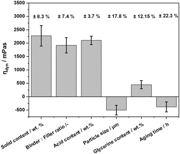 | ||
| Fig. 2 Effects of different factors of the DoE on the dispersion viscosity (standard deviation as error bars; relative error given on top). | ||
The solid content includes boehmite (Disperal) and aluminium oxide powder (Puralox SCFa 140 or Catalox HTFa 150). The DoE experiments showed a clear correlation between the amount of solid added and the viscosity with higher solid content in the dispersion leading to an increased viscosity. This observation is in-line with the literature.34 The binder![[thin space (1/6-em)]](https://www.rsc.org/images/entities/char_2009.gif) :
:![[thin space (1/6-em)]](https://www.rsc.org/images/entities/char_2009.gif) filler ratio influences the dispersion through the change in the amount of boehmite. Since boehmite is the binder material, it is responsible for the gel formation in the sol–gel-composite dispersion. A higher amount of the binder leads to the formation of a pronounced gel-network, which increases the viscosity of the dispersion.
filler ratio influences the dispersion through the change in the amount of boehmite. Since boehmite is the binder material, it is responsible for the gel formation in the sol–gel-composite dispersion. A higher amount of the binder leads to the formation of a pronounced gel-network, which increases the viscosity of the dispersion.
The acid, here HNO3, is responsible for the peptization of the boehmite particles to form a sol and is enhancing the condensation reaction converting the binder particles in the dispersion into a stable gel-network that can be packed more densely and subsequently increases the viscosity. Also, HNO3 increases the repulsive forces between the submerged particles and therefore stabilizes the dispersion. An insufficient amount of acid could lead to sedimentation of solid particles, hence affecting the viscosity negatively. The particle size shows a negative effect on the viscosity. The use of larger filler particles (Puralox SCFa 140, d50 = 30 μm) in this DoE in combination with other factors often led to sedimentation of the dispersion. By decreasing the size of the filler particles a higher surface-to-volume ratio is achieved favouring gel crosslinking of particles and thus increasing viscosity.
The addition of glycerine did not have a major positive effect on the viscosity of the dispersion. The increasing aging time, contrary to expectations, had a slightly negative effect on the viscosity. We hypothesize that there is an optimal aging time where the gel network would be completely formed, giving a viscosity profile with higher, more desired values. When this optimal duration is exceeded, the gel network collapses, and the particles entrapped within begin to sediment. On the other hand, if the aging time is shorter than the optimal duration, a certain amount of free water molecules would be present in the dispersion, leading to viscosity differences. This idea is supported by research reported by Cristiani et al.35
The evaluation of the DoE data resulted in an sol–gel dispersion recipe specifically tailored for the spray coating process, which is shown in Table 1 in comparison to the dip coating recipe, reported previously by Solymosi et al.18
Fig. 3 shows the viscosity as a function of the shear rate of the dip coating recipe and the spray coating recipe based on our DoE approach. All dispersions showed a shear thinning rheology, as expected from a boehmite sol–gel-composite.36 Since only a minor influence of aging time on the viscosity compared to other factors such as the binder![[thin space (1/6-em)]](https://www.rsc.org/images/entities/char_2009.gif) :
:![[thin space (1/6-em)]](https://www.rsc.org/images/entities/char_2009.gif) filler ratio and solid content can be derived from the DoE results (see Fig. 2) the aging times of the samples prepared according to the spray coating recipe were altered between 6 h and 16 h (see Fig. 3). Thus, a certain flexibility in the manufacturing process is offered. The small differences in viscosity between 6 and 16 h at shear rates of 20–40 s−1 are due to minor differences in the thixotropy of the samples. Moreover, the sol–gel composite dispersion obtained from the spray coating recipe showed higher viscosity values than those of the dip coating recipe (see Fig. 3), while still being easily sprayable. The increase in viscosity improved the homogeneity of the dispersion produced by the spray coating process. Germani et al. found a similar effect on the homogeneity of the coating thickness using dispersions with higher viscosity.30 In addition, the acid content could be decreased from 3.58 wt% to 2.58 wt%. This reduces the corrosion potential of the dispersion to the inner parts of the spraying gun and increases the spraying gun service time.
filler ratio and solid content can be derived from the DoE results (see Fig. 2) the aging times of the samples prepared according to the spray coating recipe were altered between 6 h and 16 h (see Fig. 3). Thus, a certain flexibility in the manufacturing process is offered. The small differences in viscosity between 6 and 16 h at shear rates of 20–40 s−1 are due to minor differences in the thixotropy of the samples. Moreover, the sol–gel composite dispersion obtained from the spray coating recipe showed higher viscosity values than those of the dip coating recipe (see Fig. 3), while still being easily sprayable. The increase in viscosity improved the homogeneity of the dispersion produced by the spray coating process. Germani et al. found a similar effect on the homogeneity of the coating thickness using dispersions with higher viscosity.30 In addition, the acid content could be decreased from 3.58 wt% to 2.58 wt%. This reduces the corrosion potential of the dispersion to the inner parts of the spraying gun and increases the spraying gun service time.
 | ||
| Fig. 3 Comparison of the viscosity of improved (6 and 16 h aging) and base sol–gel composite dispersions (4 h aging) at different shear rates. | ||
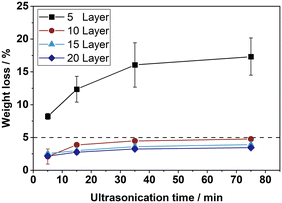
In order to compare the mechanical stability of the resulting coatings, two plates were spray-coated with dispersion manufactured according to the spray coating recipe. The metal plates were coated with 20 layers, which resulted in approx. 460 g m−2 of support coating. For comparison, two dip coated plates with about 320 g m−2 are prepared with five times dip cycles as described in the ESI† E.2 using the dip coating dispersion. The results of the stability test are shown in Fig. 4. Initial weight losses of 2.1% and 2.6% were recorded for the two spray-coated plates. These losses origin from loosely bound surface layers, which are removed immediately at the beginning of the ultrasonication test. Similar initial losses, though to a lesser extent, are found for the dip coated plates. Measurements over longer ultrasonication times show that the spray-coated layers withstand the mechanical stress for up to 75 min with only little further material losses. Overall, the ultrasonication treatment exposes the plates to a higher mechanical stress level than the conditions used during the dehydrogenation reactions. Consequently, the spray-coated plates offer a sufficient mechanical stability for our catalytic tests.
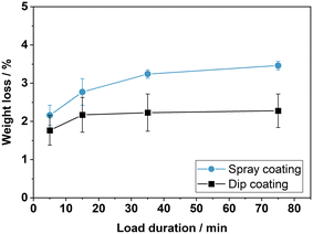 | ||
| Fig. 4 Relative loss of coating after ultrasonication of spray coated and dip coated plate catalysts. | ||
Using the spray coating process the dispersion can be evenly distributed on the plate surface. Additionally, the low binder to filler ratio in the spray coating dispersion reduces the risk of crack formation during calcination. In total this results in a robust and almost defect-free support layer (see Fig. 5(a)) produced by the spray coating process. Because the spray coating dispersion is structurally more viscous, it showed a better adherence to the metal substrate. This proved very beneficial for obtaining a homogeneous coating without any run or drop formation, especially important for the coating of non-planar geometries. For example corrugated plates as shown in Fig. 5(b) are successfully coated with the spray coating process. Moreover, the coated area was increased from 10 cm2 in the case of the planar plates to around 500 cm2 for the corrugated plates, demonstrating the scaling potential of the spray coating technology.
 | ||
| Fig. 5 Homogeneous spray-coated plates prepared with our improved sol–gel-composite dispersion (a) planar plate (b) corrugated plate. | ||
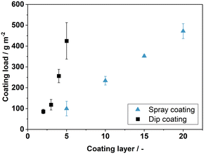
In a further series of experiments, we tried to adjust the coating thickness by variation of the number of coating steps for both the spray coating and the dip-coating process. The results are shown in Fig. 6. A linear correlation between the number of the coating cycles and the coated support mass can be derived for the spray-coated plates. The deviation shown in Fig. 6 is mainly attributed to the manual operation of the spray-gun. By doubling the number of coating layers, also the mass load of coating is doubled. For the dip coated plates, in contrast, the variation of the coating cycles leads to a clearly non-linear coating mass increase. The amount of coating that is applied per cycle is higher for the dip coating than for the spray coating, but it is highly dependent on the rheology of the dispersion. Minor differences in viscosity add up to higher variations of the coating load with an increasing number of coating cycles. Consequently, coating thickness and load could be tuned more precisely with the novel spray coating technique compared to the state-of-the-art dip coating process.
The relationship between coating load and thickness also follows a linear trend, as apparent in Fig. 7. The average relative error ![[small delta, Greek, macron]](https://www.rsc.org/images/entities/i_char_e0c5.gif) of the fit was calculated as 8.29%. Only at low coating loads a minor deviation from the linear trend is found. This implies an almost constant void fraction between the filler particles with no significant increase in bulk density at higher coating loads. As a result, we were able to precisely adjust the mass and thickness in relation to the number of coating cycles with the new spray coating technology, while maintaining a high porosity of the support coating. Additionally, the spray coatings are only applied to one side compared to the double-sided dip coating approach. This results in a more efficient use of the sol–gel composite dispersion and lower manufacturing effort, because no masking of the plate backside is required.
of the fit was calculated as 8.29%. Only at low coating loads a minor deviation from the linear trend is found. This implies an almost constant void fraction between the filler particles with no significant increase in bulk density at higher coating loads. As a result, we were able to precisely adjust the mass and thickness in relation to the number of coating cycles with the new spray coating technology, while maintaining a high porosity of the support coating. Additionally, the spray coatings are only applied to one side compared to the double-sided dip coating approach. This results in a more efficient use of the sol–gel composite dispersion and lower manufacturing effort, because no masking of the plate backside is required.
Note, that the here-described coating procedure allows preparation of coating thicknesses above 400 μm and coating loads close to 500 g m−2 while typical procedures in the literature describe only thicknesses below 100 μm and loads in the range of 1 to 100 g m−2.37–39 This increases the internal surface area of the porous layer per plate surface significantly and thereby allows the construction of higher efficient plate reactors, making CPR concept attractive for a wide range of chemical reactions. The results of the mechanical stability tests for the spray-coated plates with different coating thicknesses are shown in Fig. 8.
The metal substrates coated with 10 to 20 coating layers show a high mechanical stability, compared to the plates with only 5 coating layers. We hypothesize that the low stability of the thin layers is attributed to the internal stresses occurring during calcination. This is caused by the different heat extension coefficients of the metal substrate and the ceramic coating. To support our claim, we examined catalyst plates obtained by coatings with 5 and with 20 layers by SEM. Fig. 9 depicts the respective cross-sections. With the thinner coating, cracks, and cavities can be observed that have formed during the calcination process. Signs of partial delamination of the coated support layer from the metal substrate are seen. In contrast, no signs of delamination are found in the case of the thick coating (compare Fig. 9(a) and (b)).
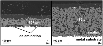 | ||
| Fig. 9 SEM cross section images of spray coated plates with different thicknesses (a) 5 layer coating (b) 20 layer coating. | ||
We conclude from these results, that our sol–gel-composite recipe and the here-selected spray coating approach are very promising to produce mechanically robust catalyst support layers, but a minimum number of at least 10 coating layers is necessary for the catalytic activation of spray-coated plates.
For introducing Pt nanoparticle onto the coated support layers, wet impregnation with a platinum sulphite acid solution (PSA) was applied. In a first set of experiments, all plates were prepared with 15 coating layers to provide equal coating loads and thicknesses. The platinum loading was varied at four levels (see ICP-AES results in Table 2) and the selected amount of platinum was always reached in one wet impregnation step. Note, that Pt loadings above 3.7 wt% could not be achieved in a one-step treatment with PSA. We attribute this fact to the maximum number of adsorption sites present in the applied support material after calcination.40
| Pt-loading | Penetration depth | Coating thickness | Coating load | BET-surface area | Average pore size | Active metal surface |
|---|---|---|---|---|---|---|
| wt% | μm | μm | g m−2 | m2 g−1 | nm | m2 gPt−1 |
| 1.0 | 64.3 ± 14.0 | 357 | 324 | 152.3 | 10.3 | 7.25 |
| 1.9 | 127.2 ± 4.0 | 354 | 345 | 153.2 | 11.4 | 47.54 |
| 2.7 | 183.3 ± 12.8 | 343 | 320 | 149.6 | 11.5 | 51.26 |
| 3.7 | 270.7 ± 15.5 | 338 | 326 | 147.4 | 11.7 | 57.38 |
The active metal surface of the plate catalysts was measured using CO-chemisorption. The results are presented in Table 2. For this set of measurements, we found that the platinum active metal surfaces of the catalyst plates increase with higher platinum loadings. This finding is counter-intuitive on the first view as many literature describes that higher Pt mass loadings lead to bigger Pt nanoparticles and thus smaller specific active metal surface.41 The unexpected behaviour of our coated samples, could be due to a higher PSA concentration in the impregnation solution, as all preparations were performed with the same amount of water as solvent. The increased PSA concentration gradient enables higher penetration depths of the Pt precursor into the support layer utilizing the full support coating thickness more efficiently. To determine the penetration depth of the platinum precursor in the wet impregnation process multiple SEM-EDX line scans of each plate cross-section were measured. Afterwards, the data was processed with a Matlab script. For the four different platinum loadings the results are listed in Table 2 and visualized in Fig. 10 in form of the average platinum EDX-signal.
 | ||
| Fig. 10 SEM-EDX signal of the platinum penetration depth for different platinum loadings on spray coated catalyst plates (average of three line-scans, standard deviation given as shaded areas). | ||
In the line scans a threshold of 200 cps was chosen as the minimum signal counted as adsorbed platinum species at one depth (dotted line in Fig. 10) to ensure a high enough noise-threshold. It is apparent that platinum is distributed deeper into the coating with higher platinum loadings instead being deposited at the outer layer. As a result, the intensity of the measurement signal does not increase with increasing platinum loading, but shows a higher cps count to greater depths. Accordingly, the absolute number of counts increases when integrating over the coating thickness, reflecting the overall increased platinum loading.
Dehydrogenation experiments with the spray-coated plate catalysts
The spray-coated and catalytically activated plates were subsequently tested in the dehydrogenation of perhydro benzyltoluene (H12-BT). The reaction progress as ΔDoDH over time is shown for the four different platinum loaded plate catalysts in Fig. 11(a). As expected for a constant feed of H12-BT, the DoDHs are increasing faster with higher platinum loadings because of the higher active metal content in the system. The plates with the highest platinum loading reached a DoDH > 80% after 6 h reaction time. Generally, only low amounts of by-products e.g. methylfluorene (<1.5%) could be detected after reaction via GC-FID (see ESI† E.8).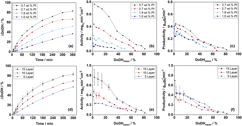 | ||
| Fig. 11 (a) Dehydrogenation progress over time (ΔDoDH), (b) activity over mean DoDH (c) productivity over mean DoDH of catalyst plates with different platinum loadings; (d) dehydrogenation progress over time (ΔDoDH), (e) activity over mean DoDH, (f) productivity over mean DoDH of catalyst plates with different coating thickness and constant Pt-loading; reaction conditions for all experiments: 250 °C; 1 atm.; 15 g H12-BT, catalyst masses and loadings see ESI† E.4. | ||
In Fig. 11(b) the activity is plotted over the mean DoDH. It is apparent that more than double the amount of hydrogen is released with the 3.7 wt% Pt compared to the 1.9 wt% Pt catalyst plate, although the amount of platinum in the system was less than doubled. This finding fits to the higher platinum active metal surface and deeper penetration depth for the coatings with higher platinum loadings (see Table 2). Also the productivity of the catalysts is increasing slightly with higher platinum loadings as depicted from Fig. 11(c). A higher hydrogen evolution rate will increase mixing in the system as well as the oscillation of gas and liquid in the pores of the catalyst and can therefore enhance the overall mass transport.42 A very attractive initial area-related activity of 0.8 mgH2 min−1 cm−2 was reached with the 3.7 wt% Pt plate catalyst, making it a suitable option for future applications in a CPR-based dehydrogenation reactor.
In Fig. 11(d) to (f), the dehydrogenation results for three different numbers of coating layers (5, 10 and 15 layers) with a platinum loading of approx. 3.7 wt% are shown. Doubling the coating layer number and, therefore, the coating thickness and load resulted in a nearly doubled activity. This indicates very effective use of the Pt loading also in the case of thicker coatings and no restriction of mass transport caused by the increasing coating thickness. The productivities shown in Fig. 11(f) support this finding, as coatings with 15 and 5 layers reached similar values. This might be attributed to the big macro pores or voids between the filler particles beneficial for the diffusion in and out of the catalyst coating (compare Fig. 9). From the tested plate catalysts the maximum coating load of the 15 layer sample introduced the greatest overall platinum quantity into the system. Consequently, the activity per macroscopic plate area is highest for this sample and is therefore of particular relevance for future CPR concepts. Even higher coating thicknesses should be targeted in further developments, if high mechanical durability and reproducibility in the manufacturing process can be maintained.
Conclusions
In summary, we have improved the recipe for manufacturing porous aluminium oxide catalyst support coatings on steel plates using spray coating of a sol–gel composite dispersion. The optimized coatings combine high alumina mass load, high thicknesses (above 400 μm), and good durability against mechanical stress. Furthermore, we adjusted the coating layer thickness precisely by varying the number of coating cycles. The proposed spray coating approach offers high flexibility in coating different line of sight geometries from small to large scale applications. In the dehydrogenation experiments, the manufactured catalyst plates showed high activities of around 0.8 mgH2 min−1 cm−2 in the dehydrogenation of H12-BT at platinum loadings of 3.7 wt% and 250 °C reaction temperature. High platinum loadings and thick coating layers proved beneficial as thicker coatings lead to higher productivities per surface area and high Pt loadings result in better utilization of the thick coating layers due to an increased penetration depth. The results obtained in this work offer a robust starting point for further upscaling of the CPR-concept for hydrogen release reactions towards larger geometries and continuous catalytic operation.Author contributions
Phillip Nathrath: methodology, investigation, validation, formal analysis, visualization, and writing of original draft; Yousuf Raed Ramzi: methodology, investigation, validation, formal analysis; Markus Bierling: investigation, proof-reading; Simon Thiele: proof-reading and supervision; Peter Wasserscheid: proof-reading, project administration and supervision; Patrick Schühle: conceptualization, proof-reading, project administration and supervision.Conflicts of interest
There are no conflicts to declare.Acknowledgements
The authors thank the German Federal Ministry for Economic Affairs and Climate Action for the financial support in the LOReley project (03EI3023F).Notes and references
- P. Preuster, C. Papp and P. Wasserscheid, Acc. Chem. Res., 2017, 50, 74–85 CrossRef CAS PubMed
.
- N. Brückner, K. Obesser, A. Bösmann, D. Teichmann, W. Arlt, J. Dungs and P. Wasserscheid, ChemSusChem, 2014, 7, 229–235 CrossRef PubMed
.
- A. Fikrt, R. Brehmer, V.-O. Milella, K. Müller, A. Bösmann, P. Preuster, N. Alt, E. Schlücker, P. Wasserscheid and W. Arlt, Appl. Energy, 2017, 194, 1–8 CrossRef CAS
.
- A. Karim, J. Bravo, D. Gorm, T. Conant and A. Datye, Catal. Today, 2005, 110, 86–91 CrossRef CAS
.
- M. F. P. Moreira, J. C. Thoméo and J. T. Freire, Ind. Eng. Chem. Res., 2005, 44, 4142–4146 CrossRef CAS
.
- A. K. Dalai and N. N. Bakhshi, Can. J. Chem. Eng., 1992, 70, 269–277 CrossRef CAS
.
- J. Kopyscinski, T. J. Schildhauer, F. Vogel, S. M. A. Biollaz and A. Wokaun, J. Catal., 2010, 271, 262–279 CrossRef CAS
.
- H. Redlingshöfer, O. Kröcher, W. Böck, K. Huthmacher and G. Emig, Ind. Eng. Chem. Res., 2002, 41, 1445–1453 CrossRef
.
- E. Tronconi and G. Groppi, Chem. Eng. Sci., 2000, 55, 6021–6036 CrossRef CAS
.
- A. Kampker, H. Heimes, M. Kehrer, S. Hagedorn, P. Reims and O. Kaul, Energy Rep., 2023, 9, 248–255 CrossRef
.
- V. Cigolotti, M. Genovese and P. Fragiacomo, Energies, 2021, 14, 4963 CrossRef CAS
.
- F. Auer, D. Blaumeiser, T. Bauer, A. Bösmann, N. Szesni, J. Libuda and P. Wasserscheid, Catal. Sci. Technol., 2019, 9, 3537–3547 RSC
.
- Clariant Ltd, EleMax® Series, https://www.clariant.com/en/Solutions/Products/2019/05/21/15/19/EleMax-Series, (accessed 24 March 2023).
- H. Jorschick, M. Geißelbrecht, M. Eßl, P. Preuster, A. Bösmann and P. Wasserscheid, Int. J. Hydrogen Energy, 2020, 45, 14897–14906 CrossRef CAS
.
- A. J. McCue and J. A. Anderson, Catal. Sci. Technol., 2014, 4, 272–294 RSC
.
- Y. Jo, T. Wan Kim, J. Oh, D. Kim and Y.-W. Suh, J. Catal., 2022, 413, 127–137 CrossRef CAS
.
- T. Rüde, S. Dürr, P. Preuster, M. Wolf and P. Wasserscheid, Sustainable Energy Fuels, 2022, 6, 1541–1553 RSC
.
- T. Solymosi, F. Auer, S. Dürr, P. Preuster and P. Wasserscheid, Int. J. Hydrogen Energy, 2021, 46, 34797–34806 CrossRef CAS
.
- J. R. Regalbuto, O. Ansel and J. T. Miller, Top. Catal., 2006, 39, 237–243 CrossRef CAS
.
- N. R. Peela, A. Mubayi and D. Kunzru, Catal. Today, 2009, 147, S17–S23 CrossRef CAS
.
-
Q. Yang, PhD thesis, University of British Columbia, 1999 Search PubMed
.
- D. A. Barrow, T. E. Petroff and M. Sayer, Surf. Coat. Technol., 1995, 76–77, 113–118 CrossRef CAS
.
- A. Montebelli, C. G. Visconti, G. Groppi, E. Tronconi, C. Cristiani, C. Ferreira and S. Kohler, Catal. Sci. Technol., 2014, 4, 2846–2870 RSC
.
-
C. J. Brinker and G. W. Scherer, Sol-Gel Science, Elsevier, 1990 Search PubMed
.
- J. J. Lannutti and D. E. Clark, MRS Online Proc. Libr., 1984, 32, 369 CrossRef CAS
.
-
Ž. R. Lazić, Design of Experiments in Chemical Engineering: A Practical Guide, Wiley, 1st edn, 2004 Search PubMed
.
-
D. Montgomery, S. Rigdon, R. Pan and L. Freeman, Design of Experiments for Reliability Achievement, Wiley, 1st edn, 2022 Search PubMed
.
-
W. Kleppmann, Versuchsplanung: Produkte und Prozesse optimieren, Carl Hanser Verlag GmbH & Co. KG, München, 10th edn, 2020 Search PubMed
.
- V. Meille, S. Pallier, G. Santa Cruz Bustamante, M. Roumanie and J. Reymond, Appl. Catal., A, 2005, 286, 232–238 CrossRef CAS
.
- G. Germani, A. Stefanescu, Y. Schuurman and A. C. van Veen, Chem. Eng. Sci., 2007, 62, 5084–5091 CrossRef CAS
.
- M. Valentini, G. Groppi, C. Cristiani, M. Levi, E. Tronconi and P. Forzatti, Catal. Today, 2001, 8 Search PubMed
.
- C. Cristiani, M. Valentini, M. Merazzi, S. Neglia and P. Forzatti, Catal. Today, 2005, 105, 492–498 CrossRef CAS
.
-
M. Geißelbrecht, Doctoral thesis, Friedrich-Alexander-Universität Erlangen-Nürnberg (FAU), 2021 Search PubMed
.
- C. R. Evanko, R. F. Delisio, D. A. Dzombak and J. W. Novak, Colloids Surf., A, 1997, 125, 95–107 CrossRef CAS
.
- C. Cristiani, M. Valentini, M. Merazzi, S. Neglia and P. Forzatti, Catal. Today, 2005, 105, 492–498 CrossRef CAS
.
- J. Bravo, A. Karim, T. Conant, G. P. Lopez and A. Datye, Chem. Eng. J., 2004, 101, 113–121 CrossRef CAS
.
- X. K. Phan, H. Bakhtiary-Davijany, R. Myrstad, P. Pfeifer, H. J. Venvik and A. Holmen, Appl. Catal., A, 2011, 405, 1–7 CrossRef CAS
.
- V. Meille, Appl. Catal., A, 2006, 315, 1–17 CrossRef CAS
.
- L. Giani, C. Cristiani, G. Groppi and E. Tronconi, Appl. Catal., B, 2006, 62, 121–131 CrossRef CAS
.
-
M. Che and C. O. Bennett, in Advances in Catalysis, Elsevier, 1989, vol. 36, pp. 55–172 Search PubMed
.
- S. Taylor, E. Fabbri, P. Levecque, T. J. Schmidt and O. Conrad, Electrocatalysis, 2016, 7, 287–296 CrossRef CAS
.
- T. Solymosi, M. Geißelbrecht, S. Mayer, M. Auer, P. Leicht, M. Terlinden, P. Malgaretti, A. Bösmann, P. Preuster, J. Harting, M. Thommes, N. Vogel and P. Wasserscheid, Sci. Adv., 2022, 8, ade3262 CrossRef PubMed
.
Footnote |
| † Electronic supplementary information (ESI) available. See DOI: https://doi.org/10.1039/d3cy01158e |
| This journal is © The Royal Society of Chemistry 2024 |

