
 Open Access Article
 This Open Access Article is licensed under a
 Creative Commons Attribution 3.0 Unported Licence
Empowering ultrathin polyamide membranes at the water–energy nexus: strategies, limitations, and future perspectives
Pulak
Sarkar
 a,
Chenyue
Wu
a,
Zhe
Yang
ab and
Chuyang Y.
Tang
*a
a,
Chenyue
Wu
a,
Zhe
Yang
ab and
Chuyang Y.
Tang
*a
aDepartment of Civil Engineering, The University of Hong Kong, Pokfulam, Hong Kong SAR, China. E-mail: tangc@hku.hk
bDow Centre for Sustainable Engineering Innovation, School of Chemical Engineering, The University of Queensland, Brisbane, QLD 4072, Australia
First published on 26th March 2024
Abstract
Membrane-based separation is one of the most energy-efficient methods to meet the growing need for a significant amount of fresh water. It is also well-known for its applications in water treatment, desalination, solvent recycling, and environmental remediation. Most typical membranes used for separation-based applications are thin-film composite membranes created using polymers, featuring a top selective layer generated by employing the interfacial polymerization technique at an aqueous–organic interface. In the last decade, various manufacturing techniques have been developed in order to create high-specification membranes. Among them, the creation of ultrathin polyamide membranes has shown enormous potential for achieving a significant increase in the water permeation rate, translating into major energy savings in various applications. However, this great potential of ultrathin membranes is greatly hindered by undesired transport phenomena such as the geometry-induced “funnel effect” arising from the substrate membrane, severely limiting the actual permeation rate. As a result, the separation capability of ultrathin membranes is still not fully unleashed or understood, and a critical assessment of their limitations and potential solutions for future studies is still lacking. Here, we provide a summary of the latest developments in the design of ultrathin polyamide membranes, which have been achieved by controlling the interfacial polymerization process and utilizing a number of novel manufacturing processes for ionic and molecular separations. Next, an overview of the in-depth assessment of their limitations resulting from the substrate membrane, along with potential solutions and future perspectives will be covered in this review.
 Pulak Sarkar | Pulak Sarkar is a postdoctoral fellow in environmental engineering working under guidance of Prof. Chuyang Tang at The University of Hong Kong (HKU). He received his BSc and MSc degrees from the University of Kalyani, and his PhD degree in chemical science from the Academy of Scientific and Innovative Research (AcSIR) under the supervision of Dr Santanu Karan in 2022. His research interests focus on the development of high-performance ultrathin reverse osmosis and nanofiltration membranes for ionic and molecular separations. |
 Chenyue Wu | Chenyue Wu is a PhD student in Environmental Engineering at The University of Hong Kong (HKU) under the supervision of Prof. Chuyang Tang. She received her master's degree in environmental engineering from The University of Hong Kong in 2021. Her current research interests focus on the transport behaviours of polyamide membranes and ion separations using nanofiltration membranes for water treatment. |
 Zhe Yang | Zhe Yang is an ARC DECRA fellow at the School of Chemical Engineering/Dow Centre for Sustainable Engineering Innovation at the University of Queensland, Brisbane, Australia. He was a Research Assistant Professor in the Department of Civil Engineering at HKU. He received his PhD degree in environmental engineering under the supervision of Prof. Chuyang Tang from HKU. He is recognized as a Top 1% Scholar worldwide ranked by Clarivate Analytics based on citations since 2023. His main research focuses on environment and sustainability using membrane technology in the context of desalination, water reuse, and water/wastewater treatment. |
 Chuyang Y. Tang | Chuyang Tang is a Chair Professor of Environmental Engineering at The University of Hong Kong. He received his BEng. and MEng. degrees from Nanyang Technological University and PhD degree from Stanford University. His research focuses on membrane synthesis and filter technology, desalination, water reuse, resource recovery, and water-energy nexus. Professor Tang is a Clarivate Highly Cited Researcher. He is a Fellow of the Royal Society of Chemistry and a Fellow of Institution of Civil Engineers. Until now, he has published over 300 refereed publications, with a total citation of more than 30 |
![[thin space (1/6-em)]](https://www.rsc.org/images/entities/char_2009.gif) 000 and an H-index of 99 (Web of Science).
000 and an H-index of 99 (Web of Science).1. Introduction
A fundamental need for living beings is freshwater. However, as a result of global population expansion, industrial development, and climate change, there is a growing shortage of freshwater all over the world.1–3 Therefore, an economical and highly energy-efficient water production technology is urgently required to address this shortage.4 Several distinct types of water purification techniques, like distillation5 and evaporation6 have been established for the production of fresh water.5 Among them, membrane-based water desalination is the most prominent growing technology currently on the market due to the low cost of operation and relatively low energy requirements for the production of freshwater.7,8Thin-film composite (TFC) membranes are the most well-known and widely used membrane categories for water desalination [e.g., reverse osmosis (RO) and nanofiltration (NF)].9 Generally, the TFC membrane possesses a composite structure, with a top layer that is created via interfacial polymerization (IP) on top of the porous ultrafiltration (UF) or microfiltration (MF) substrate, being mainly responsible for the permeation of water/solvents and separation of ions or solutes. Based on literature studies, significant work has been performed to create high-performance TFC membranes for RO or NF applications.10–12 For example, altering the interfacial kinetics,13,14 reducing the thickness of the selective layer,15 post-surface modification,16,17 introducing various sacrificial interlayers,18,19 and incorporating various nanostructures within the selective layer20–22 were all used to improve the membrane separation performance.
Over the past few decades, substantial advancements have been made in the development of a novel type of membrane – ultrathin, highly-permeable TFC membranes, which can significantly reduce energy costs and capital expenditures for water filtration.10,11,23,24 Among them, membrane thickness plays a crucial role in the transportation of water or solvents, as it is greatly affected by their permeation distance. Therefore, a very thin (or ultrathin) separation layer with a thickness of several nanometers (e.g., ∼ or <10 nm) is ideally perfect for creating a highly permeable TFC membrane while maintaining the separation performance. For example, defect-free polyamide TFC NF membranes with an ultrathin polyamide top layer of <10 nm in thickness, developed via the conventional IP method directly on top of a porous substrate, show excellent pure water permeance with a good salt rejection rate.15,25 A variety of novel fabrication techniques have also been used to create an ultrathin separation layer and its composite membranes. Notable fabrication techniques include controlling the monomer's diffusivity or reactivity at the aqueous–organic interface (e.g., support-free IP,26,27 vapor-phase IP,28,29 interlayered-based IP,30–36 additive-controlled IP,13,14,37,38etc.) and controlling the volume or concentration of the monomer to control the monomer mass during the IP process (e.g., layer-by-layer assembly,39–42 spin coating,43,44 electrospray,45–48 dual-layer slot coating,49,50 inkjet printing method,51–53etc.). These studies reveal how the amount of water transported through polyamide membranes has been significantly altered by an intrinsic or single wall thickness of the top polyamide selective layer.
Despite the potential of the ultrathin separation layer for achieving high water permeance and selective ion transport, its separation capability is yet not fully understood correctly. For instance, some experimental studies have demonstrated that the water permeance of the ultrathin membranes does not necessarily increase with the decrease in thickness of the polyamide separation layer.54 Indeed, in recent years, numerous studies have shown how the polyamide layer's properties of the composite structure are significantly influenced by the porous substrate, and how the substrate geometry limits the membrane water permeance.54,55 In addition, generating a defect-free, ultrathin polyamide separation layer on top of a porous substrate is highly challenging. The main drawback of many reported fabrication processes is their inability to produce composite membranes free of defects or pinholes, which, however, is necessary for effective salt sieving. Therefore, there is a critical gap between ultrathin membranes and high-performance membranes, and the challenge lies in achieving a thin polyamide selective layer with a defect-free and well-defined cross-linked structure in order to achieve the desired water permeance and salt rejection.
In this critical review, we highlight cutting-edge fabrication techniques for creating ultrathin polyamide membranes in order to achieve high water/solvent permeance and high salt rejection. We also discuss the limitations and future perspectives of ultrathin polyamide membranes used for ionic and molecular separation (Fig. 1). Although some recent review articles have provided a literature assessment on ultrathin membranes,56,57 the methods for creating ultrathin membranes have advanced quickly over the past years, so a critical assessment of their limitations and potential solutions for future study is still absent. Therefore, we first unlock the limitations of the ultrathin polyamide selective layer and then discuss some potential strategies to enhance the performance of ultrathin polyamide membranes. Various applications [e.g., organic solvent nanofiltration (OSN), gas separation, carbon capture, pervaporation for the separation of liquid–liquid mixtures, membrane contactors for wastewater treatment, salt–lithium separation, etc.] will be discussed to unleash the potential capability of ultrathin membranes. Finally, opportunities for other novel membrane materials (e.g., aquaporins, aligned carbon nanotubes, and graphene-based membranes) will also be highlighted.
 | ||
| Fig. 1 Illustration of the road map of ultrathin membranes that includes current fabrication strategies, limitations, and future outlooks. | ||
2. State-of-the-art strategies and approaches for creating ultrathin polyamide membranes
Interfacial polymerization is a widely recognized polymerization process employed for creating polyamide-based composite membranes. Basically, interfacial polymerization is a reaction–diffusion process that occurs mainly between two highly reactive multi-functional monomers based on the Schotten–Baumann reaction at the liquid–liquid interface between two immiscible solvents.58–60 The fundamental advantage of this method is that it enables precise control over the development of polymer films, capsules, or fibers for their use in various applications. Utilizing catalysts or initiators could sometimes accelerate the rate of a chemical reaction. The polymerization generally occurs predominantly at the interface between the activators (e.g., monomer A) and the locally available inhibitors (e.g., monomer B) in the organic phase due to the insolubility of inhibitors (e.g., monomer B) in the aqueous phase; as a result of rapid polymerization, a thin polymer film grows at the interface (Fig. 2a). Therefore, with increasing time, the reaction rate slows down and eventually stops due to the increase in the diffusion barrier or thickness of the developed polymer film as the diffusion of monomers in the organic phase is constrained by the polymer thin film that separates the two solutions and the monomers. This suggests that the film thickness created by interfacial polymerization is self-limiting as it grows very quickly at first before slowing down to reach a maximum after some time (Fig. 2a).61 The top selective layer of TFC membranes is primarily formed through an IP reaction between amine monomers [e.g., piperazine (PIP) for semi-aromatic polyamide structure and m-phenylenediamine (MPD) for fully-aromatic polyamide structure] and acyl chloride monomers [e.g., trimesoyl chloride (TMC)] at the aqueous–organic interface on top of a porous substrate [e.g., polyacrylonitrile (PAN), polysulfone (PSf), polyether sulfone (PES), etc.] (Fig. 2b).13,15 Since the IP reaction is a diffusion-limited process, highly reactive monomers initially form a dense thin layer that results in a thinner film compared to less reactive monomers. As an example, the MPD-TMC film (with an intrinsic thickness of ∼20 nm) is thinner than the PIP-TMC film (thickness of ∼100 nm) as MPD monomers are more reactive to TMC than PIP monomers.62 However, several parameters influence the morphology and thickness of the generated polymer films during the polymerization process such as solubility,63 concentration,64 reactivity,65 structure,66–69 and stoichiometry60,70,71 of the monomers, the solvent media and temperature,72,73 the diffusivity of the monomers,74 additives,75 post-treatment after IP,15etc. In the literature, a variety of fabrication techniques have been employed to develop high-performance ultrathin polyamide membranes by regulating these parameters. The following discussion covers the details of the state-of-the-art strategies for constructing ultrathin polyamide membranes.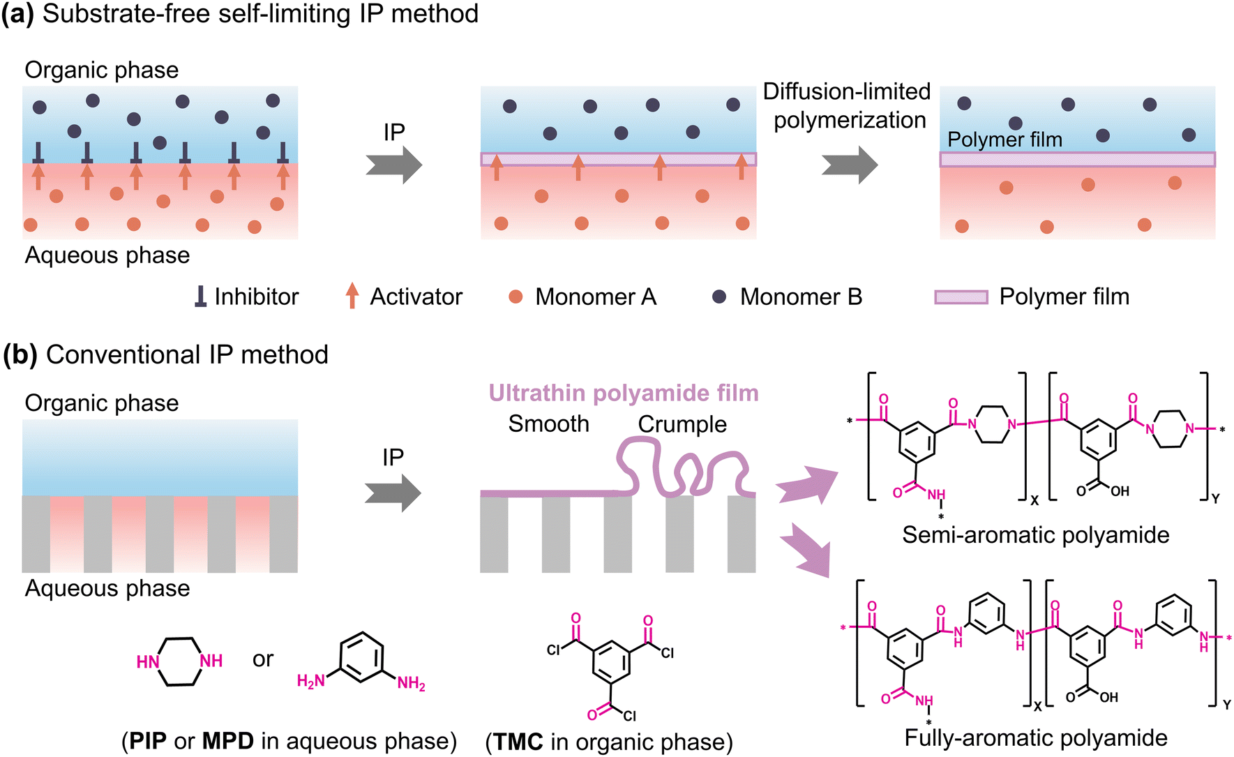 | ||
| Fig. 2 Schematic presentation of the (a) substrate-free interfacial polymerization (IP) method to form a self-limiting polymer film at the free aqueous–organic interface and (b) conventional interfacial polymerization (IP) method to fabricate polyamide TFC membranes. PIP: piperazine; MPD: m-phenylenediamine; and TMC: trimesoyl chloride. | ||
2.1. Regulation of volume or concentration of the monomers for fabricating ultrathin polyamide membranes
The concentration and volume or mass of the reacting monomers are the key factors in controlling the thickness of the top polyamide selective layer. In most fabrication techniques, the regulation of monomer concentration from low to high has been extensively used to create ultrathin membranes (Table 1).18,25 Since reducing the volume or mass of the monomers is crucial for cutting down the overall manufacturing cost for large-scale fabrication processes, recent studies concentrated on finding ways to regulate the volume or mass of the monomers used to create ultrathin membranes while maintaining the separation performance. In the following sections, some specific fabrication techniques utilized to regulate the volume or mass of the monomers for the fabrication of ultrathin membranes are covered.| Fabrication method | Membrane | Material used | Separation performance | PA layer thickness [nm] | Ref. | |
|---|---|---|---|---|---|---|
| Permeance [L m−2 h−1 bar−1] | Rejection [%] | |||||
| Nanofiltration (NF) membranes | ||||||
| Conventional IP | Ultrathin polyamide films | PIP/TMC | 46.6 for water | 98.1 for Na2SO4 | 8.5 | 25 |
| IP followed by post-treatment | Sub-5 nm polyamide nanofilms | PIP/TMC | 61.3 for water | 99.5 for Na2SO4 | 4.6 | 15 |
| Molecular layer-by-layer (mLbL) | Ultrathin films of organic networks | TPMC/TAPM | 17.8 for water | 87.4 for Na2SO4 | 16.6 | 39 |
| Ultrathin microporous polyamide films | TAPB/TMC | 8.4 for ethanol | 86.0 for methyl orange | 17 | 42 | |
| Spin coating | Spin-assisted GO–polyamide membranes | GO-PIP/TMC | 35.1 for water | 93.6 for Na2SO4 | 20 | 89 |
| Spin-coating assisted ultrathin membranes | PIP/TMC | 36.1 for water | 96.2 for Na2SO4 | 9.7 | 43 | |
| Electrospray | Ultrathin polyamide membranes | MPD/TMC | 11.1 for water | 57.0 for Na2SO4 | 10.8 | 45 |
| Polyamide membranes with hierarchical nanostructures | PEI/TMC | 23.7 for water | >95 for brilliant blue | 13.8 | 48 | |
| Support-free IP | Nanofilm composite membranes | PDA-PIP/TMC | 25.1 for water | 99.1 for Na2SO4 | 12 | 103 |
| Vacuum-assisted IP | Polyamide membranes via vacuum-assisted IP | PIP/TMC | 20 for water | 99.6 for Na2SO4 | 19.2 | 114 |
| Diffusion-controlled IP | Turing type polyamide membranes | PVA-PIP/TMC | 26.0 for water | 99.6 for Na2SO4 | ∼20 | 117 |
| Ultraselective polyamide membranes | SLS-PIP/TMC | 23.1 for water | 99.95 for Na2SO4 | ∼12 | 13 | |
| Ultra-permselective NF membranes | PCS-PIP/TMC | 44.7 for water | 98.0 for Na2SO4 | 14 | 37 | |
| MONs assisted NF membranes | MONs-PIP/TMC | 41.7 for water | 98.0 for Na2SO4 | 15 | 20 | |
| Interlayered IP | SWCNT film supported NF membranes | PD/SWCNTs-PIP/TMC | 32.0 for water | 95.9 for Na2SO4 | 12 | 30 |
| SWCNTs supported membranes | SWCNT-PIP/TMC | 40 for water | 96.5 for Na2SO4 | 15 | 34 | |
| COF supported polyamide membranes | COF-PIP/TMC | 31.1 for water | 95.0 for Na2SO4 | 20 | 36 | |
| Ultrathin TFC polyamide membranes | PVA-PIP/TMC | 31.4 for water | 99.4 for Na2SO4 | 9.6 | 133 | |
| In situ free IP | Ultrathin film composite membranes | PIP/TMC | 26.6 for water | 98.7 for Na2SO4 | 13.4 | 54 |
| Reverse osmosis (RO) membranes | ||||||
| Molecular layer-by-layer (mLbL) | TFC RO membranes | MPD/TMC | 1.4 for water | 95.7 for NaCl | 20 | 40 |
| Tailor-made polyamide membranes | PEI/PAA-MPD/TMC | 1.5 for water | 98.2 for NaCl | 25 | 41 | |
| Dual-layer slot coating | TFC RO membranes | MPD/TMC | 2.1 for water | 99.1 for NaCl | 8.8 | 49 |
| Interfacial adhesion tailored TFC RO membranes | PDA-MPD/TMC | 2.6 for water | 99.5 for NaCl | 7.2 | 50 | |
| Vapor phase IP | TFC membranes without using organic solvents | MPD/TMC | 3.3 for water | 94.3 for acridine orange | 12.4 | 28 |
| Support-free IP | TFC RO membranes via support-free IP | MPD/TMC | 0.9 for water | 99.0 for NaCl | 17.1 | 27 |
| Ultrathin polyamide nanofilms for RO | MPD/TMC | 2.69 for water | 96.0 for NaCl | 6.5 | 26 | |
| Vacuum-assisted IP | TFC RO membranes via vacuum-assisted MPD loading | MPD/TMC | 2.8 for water | 98.7 for NaCl | 16.6 | 115 |
| Interlayered IP | Sub-10 nm polyamide nanofilms | MPD/TMC | 3.1 for methanol | 99.7 for methyl orange | 8.4 | 18 |
| Dual-layer IP strategy | Asymmetrical ultrathin polyamide membranes | PIP/TMC – MPD/TMC | 2.86 for water | 97.3 for NaCl | 13 | 173 |
| In situ free IP | Ultrathin film composite membranes | MPD/TMC | 2.9 for water | 98.3 for NaCl | 6.7 | 54 |
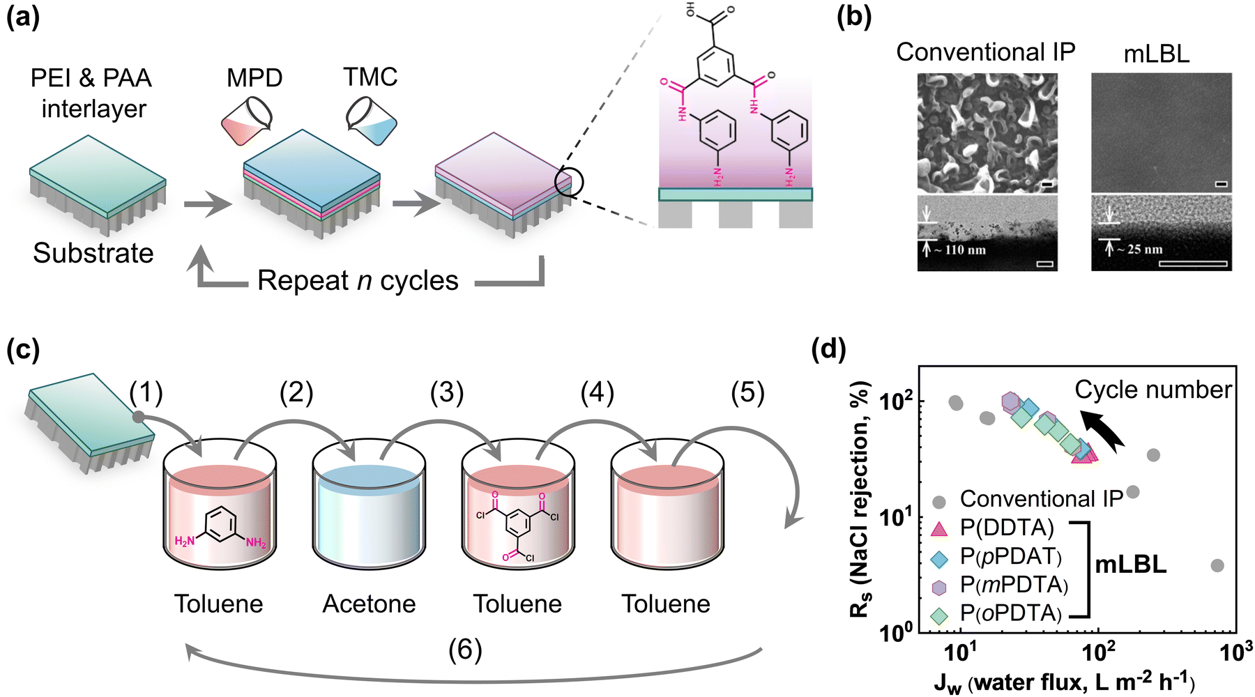 | ||
| Fig. 3 (a) Strategies for creating polyamide TFC membranes via mLbL assembly method, and (b) the control of surface morphology from crumpled to smooth with desired thickness using the mLbL assembly method (scale bar is 100 nm for all SEM and TEM images). Scanning electron microscopy and transmission electron microscopy images are reproduced with permission from ref. 40, Copyright 2013, WILEY-VCH. (c) Fabrication of polyamide TFC membranes using the mLbL method by dipping in various monomer solutions. (d) The figure presenting the NaCl rejection vs. water flux of the prepared TFC membranes. These values are adapted from ref. 41. | ||
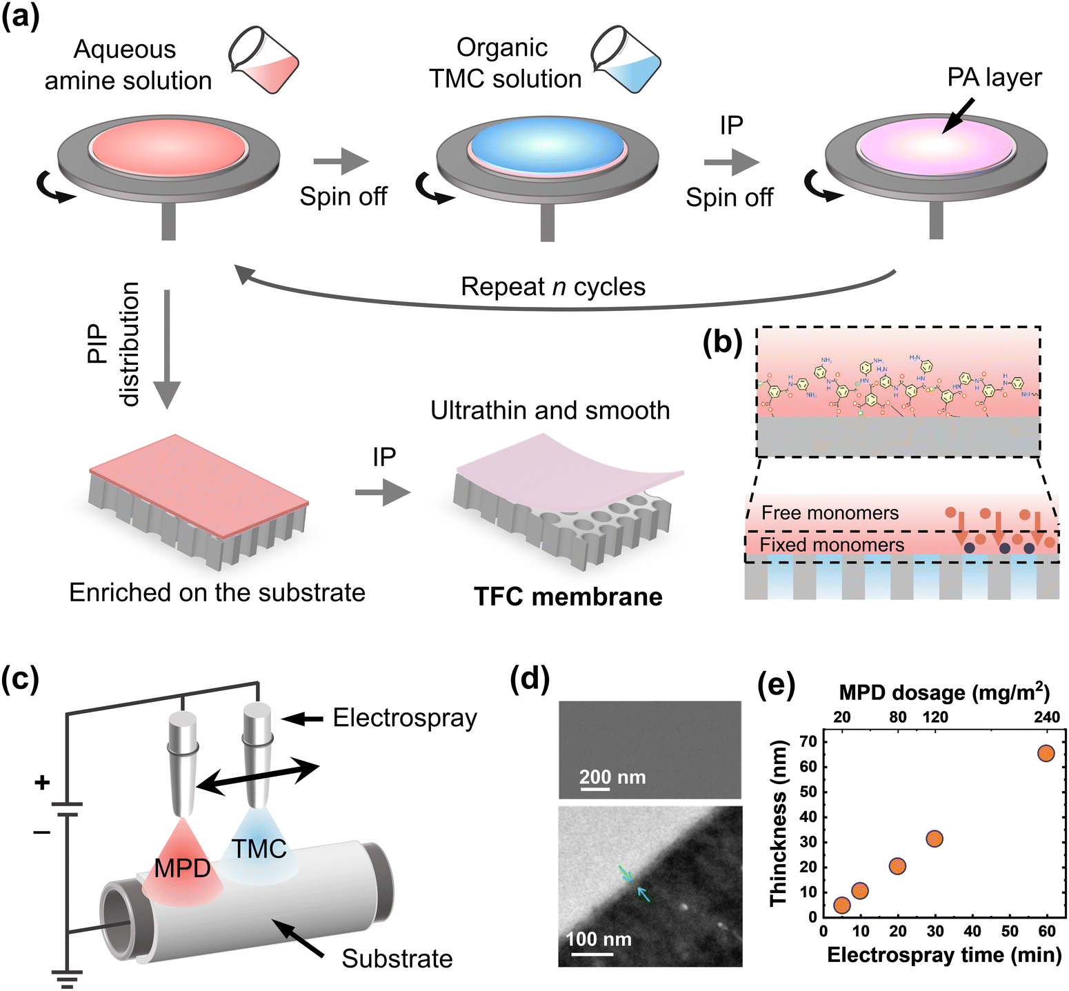 | ||
| Fig. 4 (a) Step-by-step fabrication of polyamide thin film composite membranes via the spin-coating assisted IP method on top of porous substrate. (b) A possible mechanism of how spin-coating helps in reducing the diffusion of the monomers and making a stable reaction zone during the film formation. (c) An illustration of the electrospray method from the side and from the top and (d) SEM and TEM images of the polyamide membranes. Scanning electron microscopy and transmission electron microscopy images are reproduced with permission from ref. 45, Copyright 2018, American Chemical Society. (e) Thickness variation of the fabricated polyamide membranes with different electrospraying times and MPD dosages. These values are adapted from ref. 45. | ||
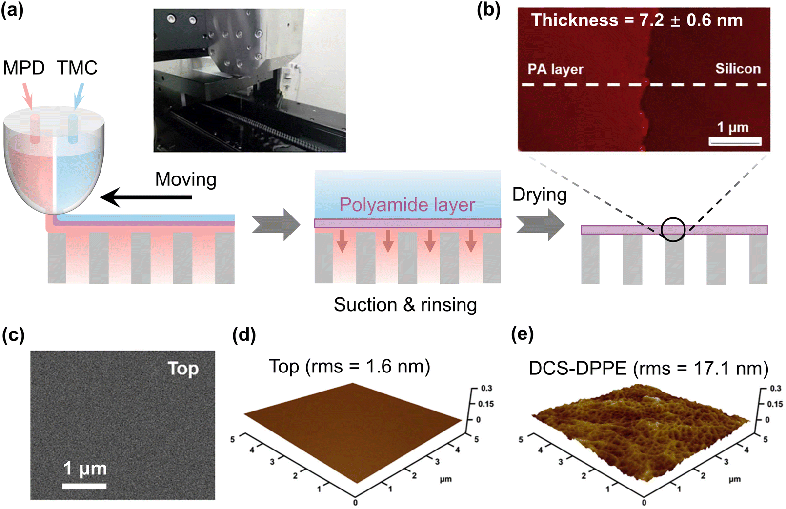 | ||
| Fig. 5 (a) Schematic view of the fabrication of polyamide membranes via the dual-layer slot coating method. (b) Cross-sectional AFM image of the polyamide layer on top of the silicon wafer surface. (c) SEM surface morphology, (d) AFM surface morphology, and (e) surface root-mean-square-roughness (rms) of the fabricated polyamide layer using the DSC method. Reproduced with permission from ref. 50, Copyright 2020, Elsevier B.V. | ||
Several different approaches for creating ultrathin membranes have been reported in the literature that are similar to the vapor phase IP method. For example, diamond-like carbon (DLC) membranes have been created using the chemical vapor deposition (CVD) process since the early 1990s.100,101 In 2012, a parallel-plate plasma-enhanced CVD reactor was employed to develop ultrathin freestanding DLC membranes.102 The fabricated membranes exhibit extremely high mechanical strength and excellent stability in organic solvents since sp3 carbon networks are present within the structure.102 As a result, the CVD approach provides an effective method for producing membranes with adjustable thickness. In the future, high-performance ultrathin membranes can be developed via the layer-by-layer (LbL) CVD process to tune the membrane properties for their use in ionic and molecular separation applications.
2.2. Controlling the diffusivity/reactivity of the monomers at the aqueous–organic interface
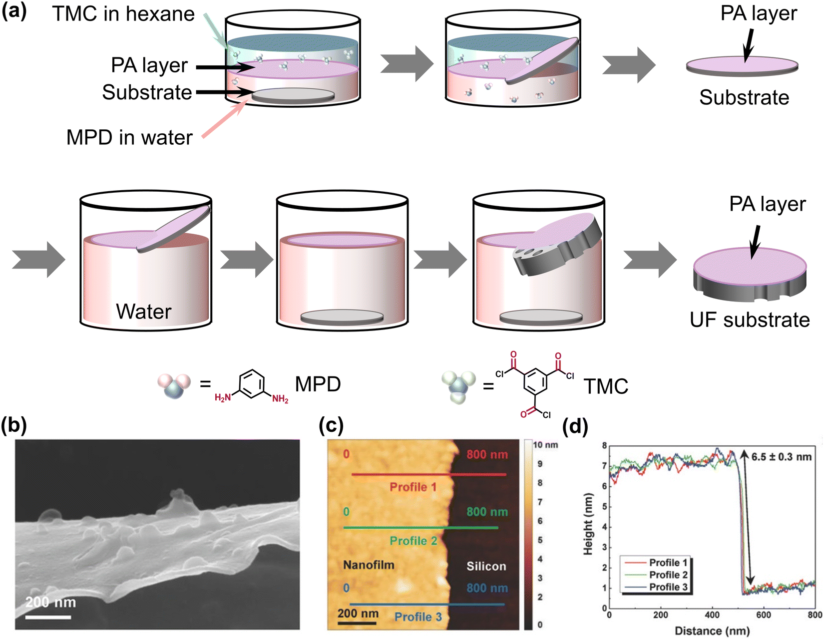 | ||
| Fig. 6 (a) Step-by-step schematic presentation of freestanding polyamide film created at the free aqueous–organic interface followed by transferring onto porous substrates. (b) SEM cross-sectional image of the freestanding polyamide film, and (c) and (d) cross-sectional AFM image along with the height profile of the polyamide film on top of the silicon wafer. Reproduced with permission from ref. 26, Copyright 2018, Wiley-VCH. | ||
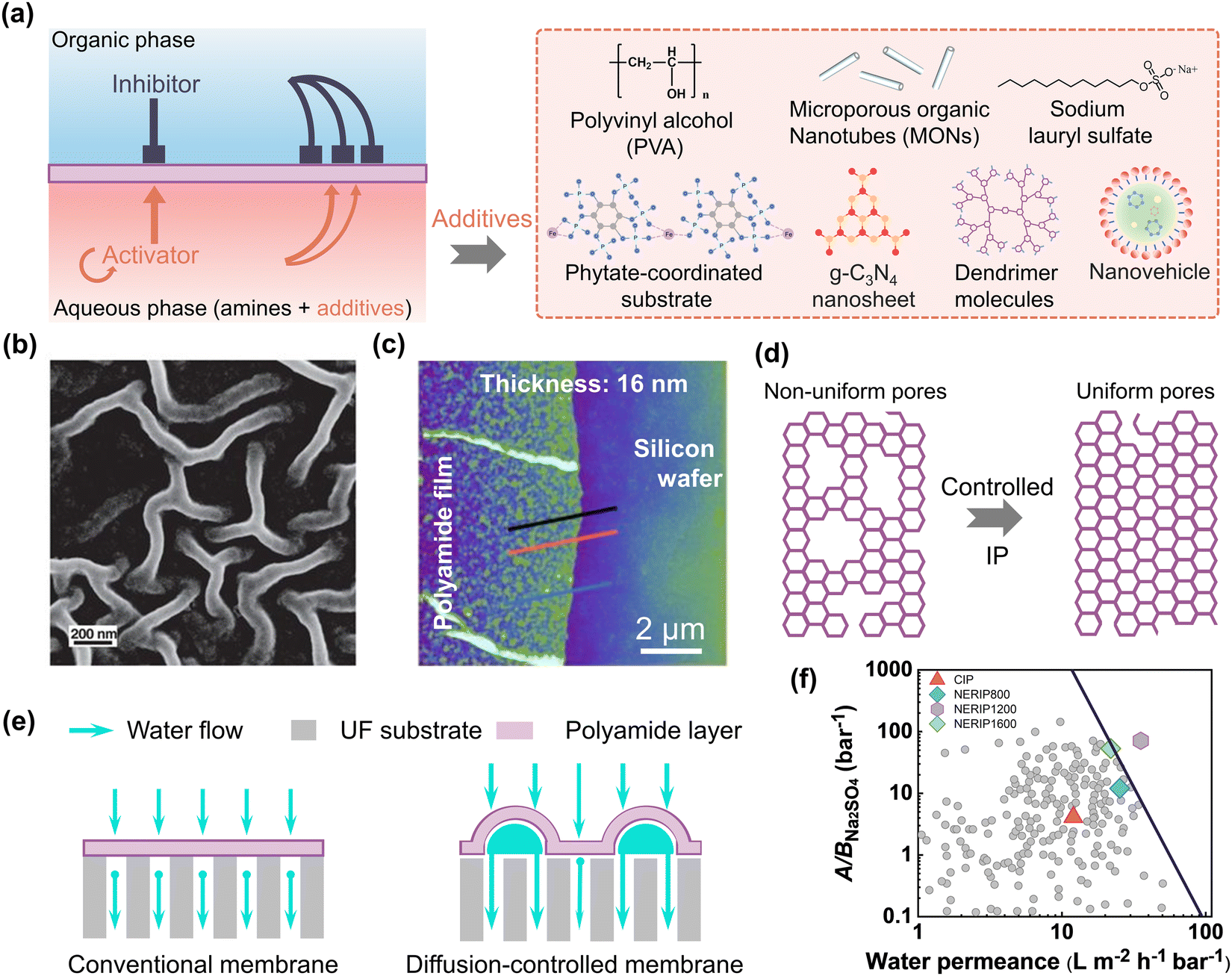 | ||
| Fig. 7 (a) A schematic representation of the diffusion-controlled IP method that uses different additives to produce polyamide membranes during IP. (b) SEM images of the crumpled membranes produced by the diffusion-controlled IP technique. Reproduced with permission from ref. 117, Copyright 2018, American Association for the Advancement of Science. (c) AFM cross-sectional images of the ultrathin polyamide nanofilms formed with diffusion-controlled IP method. Reproduced with permission from ref. 20, Copyright 2022, Springer Nature. (d) A schematic representation of the polyamide network structure showing the uniformly produced pore size distribution in the presence of additives. (e) A schematic representation of the transport of water across the smooth and wrinkled membranes that are created in the presence of additives. (f) An overview of the water/Na2SO4 selectivity and water permeance of the state-of-the-art NF membranes as reported in the literature. These values are adapted from ref. 22. | ||
 | ||
| Fig. 8 (a) Illustration of the step-by-step fabrication of ultrathin polyamide nanofilm composite membranes on top of UF substrate membranes using a sacrificial interlayer. (b) and (c) Cross-sectional SEM images of the smooth and crumpled nanofilms formed in the presence of the sacrificial nanostrand interlayer. Reproduced with permission from ref. 18, Copyright 2015, American Association for the Advancement of Science. (d) Cross-sectional TEM image of the ultrathin polyamide membrane prepared on the SWCNT interlayer-coated PES substrates. Reproduced with permission from ref. 34, Copyright 2019, American Chemical Society. (e) Schematic presentation of water transport across interlayered-based TFC membranes. (f) Summary of water permeability and Na2SO4 rejection of the state-of-the-art NF membranes reported in the literature. These values are adapted from ref. 34. (g) Water permeability and NaCl/MgSO4 selectivity trade-off of the state-of-the-art NF membranes. These values are adapted from ref. 34. | ||
3. Limitations and critical analysis of ultrathin polyamide membranes
Water permeance is significantly impacted by the thickness of the top polyamide selective layer. Undoubtedly, a thinner membrane exhibits exceptional water permeance in comparison to its thicker counterpart. Although polyamide membranes with an ultrathin selective layer demonstrate good separation performance, it is noticed that the rate of increasing water permeance does not follow a linear trend with the reduction of top polyamide layer thickness.54 The plot illustrating experimental results on how water permeance and permeability varied with various polyamide film thicknesses is presented in Fig. 9a.54 The observed or apparent water permeance (Aobs) was found to increase with decreasing film thickness, but not proportionally. Furthermore, as layer thickness decreases, the observed water permeability (Kobs) is reduced. These observations are counterintuitive since for an ideal membrane, the intrinsic water permeability (Kideal) would remain constant regardless of the film thickness, and the water permeance would increase proportionally with decreasing film thickness based on the one-dimensional solution–diffusion model.134 This phenomenon can be resolved by recognizing that the effective water transport length (leff) does not directly correlate linearly with the film thickness (lPA) due to the presence of the porous substrate (Fig. 9b and c). As a result, reducing the thickness of the top polyamide selective layer in order to create a highly permeable composite membrane is not as effective as it should be due to the additional hydraulic resistance arising from the substrate geometry in both the normal (or perpendicular to the thickness) and transverse (or diagonal to the thickness) directions. Therefore, for effective water transport, the lateral mass transfer resistance and the normal resistance sitting above the substrate pores are the key factors that hinder the actual water flow while reducing the polyamide film thickness.55 Therefore, it is necessary to properly understand and overcome these limitations to develop high-performance ultrathin polyamide membranes.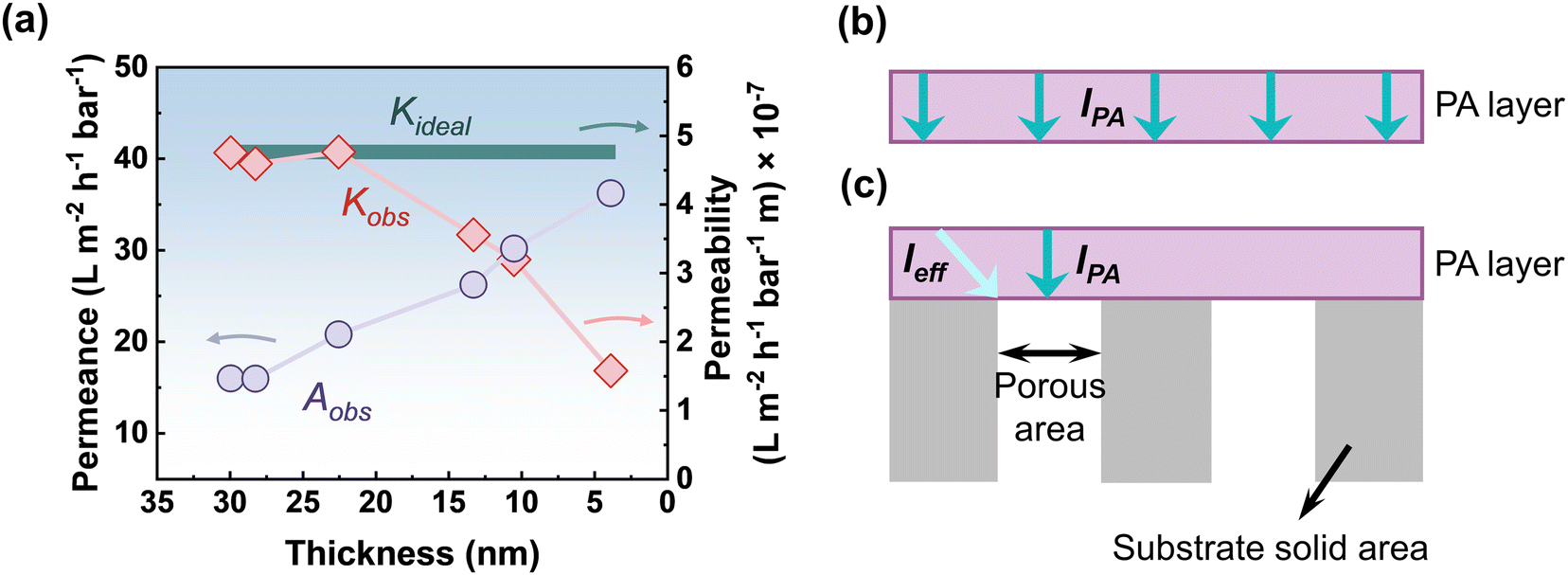 | ||
| Fig. 9 (a) Plot showing the variation of water permeance and the corresponding permeability of nanofiltration membranes with decreasing thickness of the top polyamide selective layer. These values are adapted from ref. 54, Copyright 2020, American Chemical Society. The illustration shows the transport of water across (b) a freestanding thin film, and (c) a thin film that is supported by a porous substrate membrane. The observed permeability (Kobs) decreases as the thickness gets thinner and does not follow the ideal permeability (Kideal) lines as the effective transport length (leff) is not directly linear with the film thickness (lPA). | ||
3.1. Role in water transport
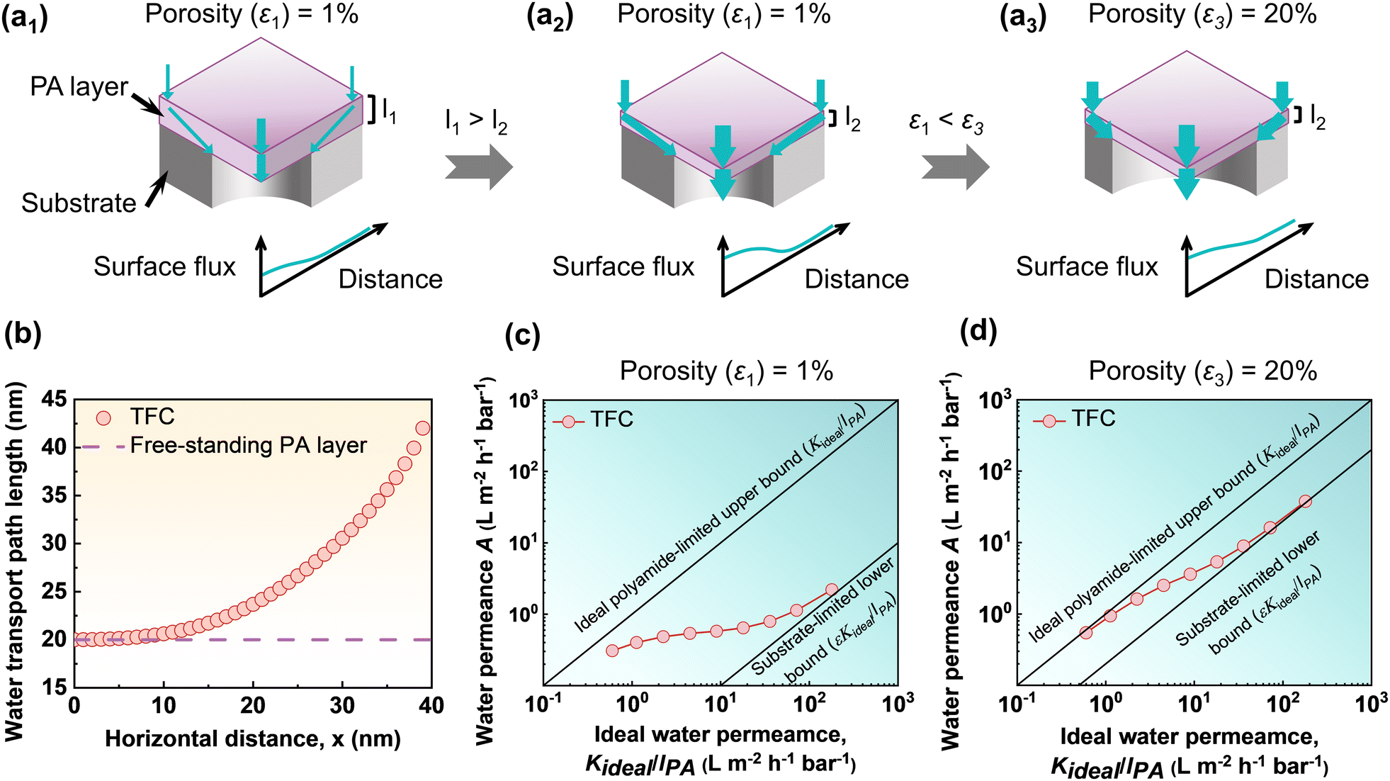 | ||
| Fig. 10 Schematic view of the transport of water through the polyamide TFC membranes where (a1) and (a2) show the effect of polyamide layer thickness, and (a2) and (a3) show the effect of substrate porosity. (b) The water transport path length in terms of the location of the path of the freestanding polyamide film and the conventional TFC membranes. (c) and (d) The plot shows the relationship between the ideal water permeance for a self-standing/freestanding polyamide film and the available water permeance for TFC membranes with various substrate porosities (ε) at (c) ε1 ∼ 1% and (d) ε3 ∼ 20%. These values are adapted from ref. 55, Copyright 2022, American Chemical Society. | ||
In addition to the thickness of the top polyamide layer, the performance of polyamide TFC membranes is substantially impacted by the porosity of the substrate membrane. As an example, for low porosity membranes (e.g., porosity, ε1 ∼ 1%), water molecules need to travel through the membrane substrate's pores in both the normal and transverse directions, requiring longer transport pathways to arrive at the porous zone of the substrate membrane (Fig. 10a2). Whereas for higher porosity membranes (e.g., porosity, ε3 ∼ 20%), a large number of pores helps to reduce the transverse or lateral distance of the water molecules to arrive at the porous zone of the substrate membrane (Fig. 10a3). In the modeling study by Tang and co-workers,55,140 it was revealed that the substrate-limited upper bound of the typical TFC membranes approaches the ideal polyamide-limited upper bound when substrate porosity (ε) increases from 1 to 20% by significantly shortening the effective transport distance for water molecules (Fig. 10a2, a3, c and d). As a result, the funnel effect is less pronounced for the higher porosity substrate membrane than for the low porosity substrate membrane. Nevertheless, it is important to note that the fabrication of ultrathin membranes on top of high-porosity substrates could be more challenging, and the resulting membrane may also face poor mechanical stability.
Introduction of an interlayer as a gutter layer. To address the discussed permeation limitations due to the substrate, three layers of composite structures have been developed, with the addition of a third highly permeable interlayer, or the so-called ‘gutter’ layer between the top polyamide selective layer and the substrate membrane, as illustrated in Fig. 11a1 and a2. In the literature, many researchers introduced numerous high-permeability materials as interlayers or gutter layers. For example, silver nanoparticles,123,142 3D porous materials (e.g., metal–organic frameworks,113 and covalent organic frameworks36,143), carbon nanotubes,32,34,144 2D materials (e.g., graphene oxide89,145 and MXene144,146,147), tannic acid/Fe3+ complexes,148,149 and polydopamine coatings150,151 have been extensively employed as an interlayer to enhanced the separation performance of the polyamide-based TFC membranes (Fig. 11a1 and a2). The high permeability interlayer helps to improve the effective water permeance of the TFC membranes by reducing the geometrical restriction that arises from the substrate membrane. The presence of the high permeability interlayer within the polyamide TFC membranes strengthens the water transport channel and results in a more uniform flux distribution.132 Additionally, the presence of the interlayer may eliminate the extremely high localized flux hotspots, which may in turn reduce the tendency of membrane fouling.152,153 Besides this, examining the utilization of specific interlayer material chemistry to increase selectivity against targeted contaminants is a promising area for future research.154–156 Therefore, further research is required to gain a deeper understanding of the gutter layer's impact to further enhance the separation performance of TFC membranes. In order to thoroughly assess the effect of interlayer during the growth of polyamide films, membrane thickness, surface morphology, the degree of cross-linking, and separation performance (e.g., water permeability, selectivity, antifouling properties, chlorine resistance, etc.), more modeling and experimental studies need to be conducted. Some 2D analytical models,157,158 and 3D computational models139 have previously been utilized to study the impact of the interlayer on water transport through the composite membrane. However, the behavior of membrane transport has not been adequately addressed using this model. An in-depth understanding of the mechanism of water transport through polyamide membranes was critically demonstrated in a recent study by Tang and co-workers55,140 using a three-dimensional (3D) simulation.55 The modeling study effectively addressed the influence of the geometry-induced funnel effect and the interlayer-promoted gutter effect in terms of various substrate porosities by plotting the water permeance as a function of ideal water permeance (Fig. 11c–e).55Fig. 11c–e reveal that the use of a highly permeable interlayer between the polyamide selective layer and substrate membrane helps to reduce the funnel effect. The addition of the highly permeable interlayer effectively enhances the transport of water molecules in the transverse direction towards the substrate porous area, which minimizes the geometric restriction by reducing the overall hydraulic resistance and the funnel effect. Additionally, relative hydraulic water permeability (n), i.e., the ratio between the water permeability of the interlayer and the top polyamide selective layer, plays a significant role. The influence of relative hydraulic water permeability (n) is also shown in Fig. 11c, which demonstrates that for a high permeable interlayer (as an example, for an n value of 1000), the permeance curve (TFNi for n = 1000) moves closer to the ideal polyamide-limited upper bound. Additionally, in the presence of an interlayer, the substrate porosity also contributes significantly, pushing the permeance curve closer towards the ideal polyamide-limited upper bound (Fig. 11c–e). As seen from Fig. 11c–e, when substrate porosity (ε) increases from 1 to 20%, the permeance curve (TFNi for n = 1000) almost matches with the ideal polyamide-limited upper bound line, resulting in almost 100% water permeance efficiency. As a result, employing a high permeability interlayer with a higher substrate porosity enables the maximum gutter effect and thus completely eliminates the geometrical restrictions imposed by the substrate membrane.
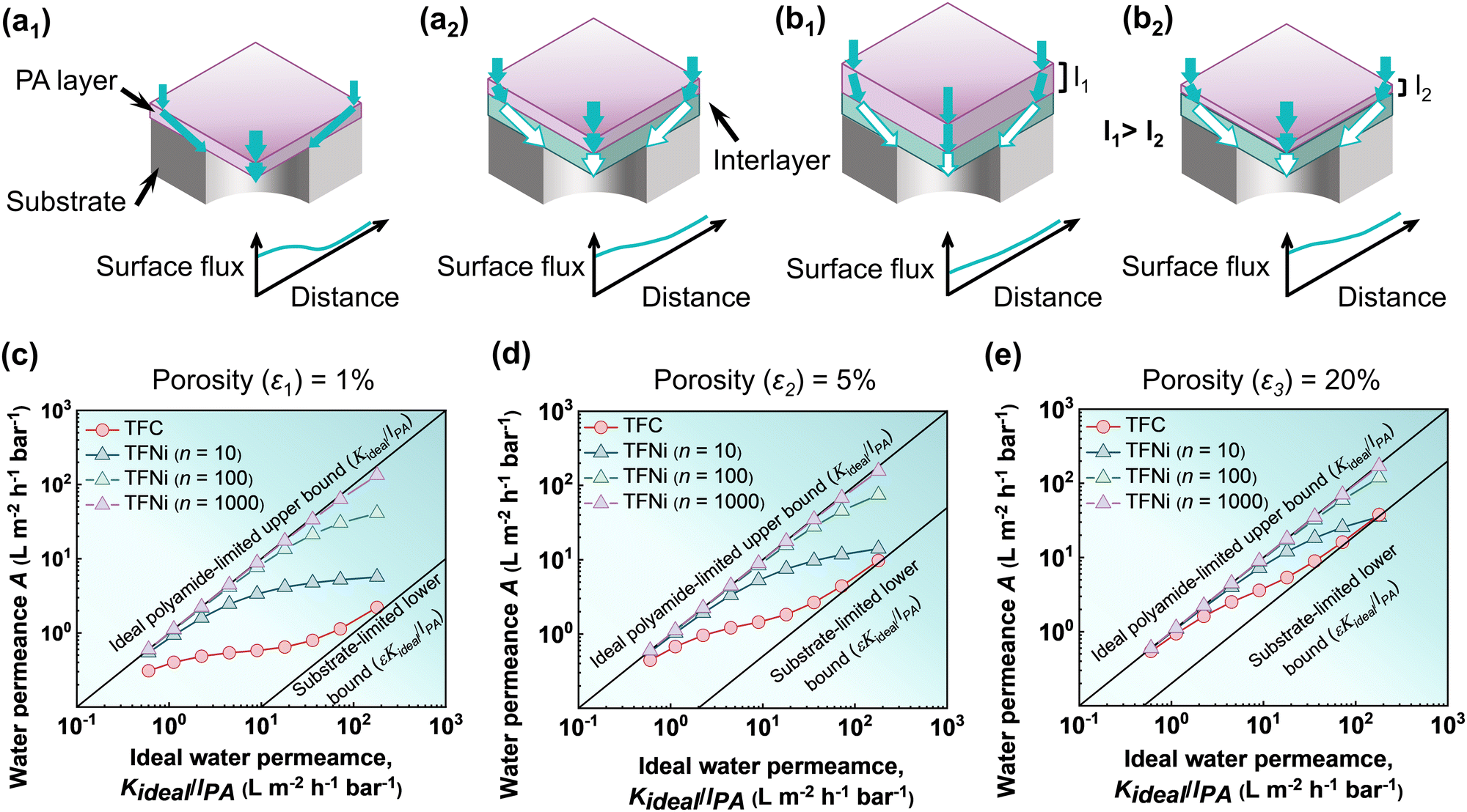 | ||
| Fig. 11 Schematic view of the water transport through the polyamide TFC membranes where (a1) represents a typical TFC membrane, (a2) represents an interlayered thin-film nanocomposite (TFNi) membrane, and (b1) and (b2) show the effect of polyamide layer thickness. (c)–(e) The plot shows the relationship between the ideal water permeance for a self-standing/freestanding polyamide film and the available water permeance of interlayered TFNi membranes with different relative hydraulic water permeability (for n values of 10, 100, and 1000) and with various substrate porosities (ε) at (c) ε1 ∼ 1%, (d) ε2 ∼ 5%, and (e) ε3 ∼ 20%. These values are adapted from ref. 55, Copyright 2022, American Chemical Society. | ||
The effect of polyamide selective layer thickness after introducing the interlayer was also investigated through the modeling study (Fig. 11b1, b2, c–e).55 The modeling analysis reveals that interlayer-based membranes generally exhibit very limited gutter effects on water transport for thicker polyamide selective layers (such as a thickness of 160 or 300 nm) in comparison to the thin polyamide selective layer (Fig. 11c–e). This suggests that, for a very thick polyamide selective layer, the total transport resistance resulting from the substrate membrane is dominated by the transport distance in the normal direction rather than the transverse or lateral direction. As a result, the effectiveness of high permeability interlayers in reducing the transverse transport resistance becomes extremely limited for thicker polyamide TFC membranes. It is therefore more effective to design polyamide membranes with an ultrathin selective layer following the addition of a high permeability interlayer since the gutter effect becomes more prominent in comparison with the thicker polyamide selective layer. Although the creation of ultrathin membranes demonstrates an impressive performance improvement in contrast to the other methods, the funnel effect that arises from the substrate membrane restricts the ideal performance enhancement of the ultrathin membranes. Therefore, the above-discussed mechanism describes how regulating the porosity of the substrate membrane and the introduction of the interlayer could successfully mitigate the existing geometrical restrictions and will considerably help to unleash the potential of ultrathin membranes in future studies.
Creation of crumpled morphology of the polyamide selective layer. According to the literature, a crumpled surface of the top polyamide layer significantly improves the water permeance of the polyamide RO/NF membranes.116,117,149 The crumpled structure considerably increases the membrane's effective surface area, enabling it to enhance the overall water permeability rate (Fig. 12a1 and a2).117,140 The improved water permeance of the crumpled membranes has been elucidated through several explanations, including an increased effective surface area for filtration, a thinner polyamide layer, and the promotion of water transport pathways.140 The performance enhancement in terms of the membrane surface area is summarized and plotted based on literature results (Fig. 12b1). It is interesting to see that the increased membrane surface area alone cannot fully explain the experimentally observed flux enhancement; the experimental data are generally above the theoretical line, suggesting additional mechanisms. This additional mechanism was coined by Tang and co-workers55,140 introducing the self-gutter effect which greatly shortened the water transport pathways with more uniform flux distribution. As previously discussed, the effective water transport distance (leff) for a conventional smooth TFC membrane is considerably higher compared to the intrinsic thickness of the top selective layer (lPA), resulting in a significantly elevated funnel effect, lowering the water permeation rate in comparison to the freestanding polyamide film (Fig. 12a1). The funnel effect can be significantly overcome by creating crumple polyamide membranes as they contain free voids on top of the porous substrate, which potentially shorten the effective water transport distance in the polyamide film (Fig. 12a2).137,139,159 As demonstrated by Tang and co-workers55,140 the crumpled structure in TFC RO/NF membranes containing nanovoids behaves as a high permeability interlayer, which greatly helps in increasing the water permeation rate by reducing the overall transport pathways. This behavior is similar to the interlayer-promoted gutter effect, which is also rationalized as the self-gutter effect, thus contributing to the overall water permeance.55 The growth of crumpled morphology along with an increase in the membrane surface area is often additionally associated with a decrease in the thickness of the polyamide top selective layer (Fig. 12b2).37,160–162 Experimental observations show that the water permeance of crumpled membranes may increase by nearly an order of magnitude, which can be explained by the synergistic effect of reduced polyamide thickness and increased surface area ratio (Fig. 12b3). As shown in Fig. 12c, the additional advantage of enhanced filtration area causes the water permeance of crumpled membranes to surpass the ideal water permeance of smooth membranes. Whereas, the theoretical results successfully demonstrate that the synergetic action of the crumpled membranes with increasing effective filtration area in combination with the thinner polyamide layer optimizes the water transport channels, leading to the highest enhancement in water permeance (Fig. 12c).55,140 Therefore, in order to improve the overall membrane separation performance, it appears that the creation of crumpled polyamide films with a thinner or ultrathin rejection layer could provide an excellent approach in future studies and this can be achieved by modulating the monomer's reactivity, which leads to a higher enthalpy of formation, generating more heat and creating strip or crumpled structures.116,140
 | ||
| Fig. 12 Schematic view for illustrating the water transport for (a1) typical TFC membranes, and (a2) crumpled TFC membranes, where leff defines the effective transport length, and lPA defines the intrinsic thickness of the top polyamide selective layer. Figures are adapted with permission from ref. 140, Copyright 2022, American Chemical Society. A plot of the literature data on crumpled NF membranes in terms of the increase in permeance with (b1) an increase in the surface area, (b2) a decrease in the thickness of the top layer, and (b3) the couple effects of the surface area combined with the thickness reduction. The theoretical performance improvement resulting from the reduced thickness and surface area is shown by the y = x line. (c) The benchmark of the theoretical water permeance improvement in terms of substrate porosity for a freestanding film, crumple polyamide film, and crumple and thin polyamide film. These values are adapted from ref. 140, Copyright 2022, American Chemical Society. | ||
3.2. Role in solute rejection/ion selectivity
Recent progress in TFC RO/NF membrane development has employed a variety of techniques to create highly permeable desalination membranes such as controlling the thickness and effective surface area of the top polyamide selective layer.18,40,46,117 However, in the creation of ultrathin membranes to increase the water permeability of the polyamide composite membranes, the solute separation or the solute–solute selectivity may be compromised since the structural properties of the top layer have some additional impacts on the overall separation performance. For example, the density and nanoscale structural inhomogeneity of the top polyamide selective layer play a significant role in the membrane transport behavior.163,164 Therefore, it is highly important to design an ultrathin polyamide membrane with a more homogenous and narrowest density distribution in order to simultaneously enhance water permeance and water–solute or solute–solute selectivity. Additionally, the selectivity of polyamide membranes is substantially influenced by the interior and exterior charge density of the top selective layer.165 For solute separations through nanofiltration membranes with a thin polyamide selective layer, it is considered that the Donnan exclusion effect (charge–charge repulsion) becomes more significant compared to the steric hindrance exclusion (pore size exclusion).54 For this reason, the regulation of membrane charge has been widely employed to enhance NF performance.166–168 Therefore, to design highly selective membranes, a polyamide selective layer with minimum thickness that can generate a significant Donnan exclusion effect and a high degree of network cross-linking is highly desired. Furthermore, since the polyamide-based TFC RO/NF membranes are created on top of a porous substrate to provide mechanical support for the top polyamide selective layer, it is essential to maintain an adequate degree of cross-linking in the network structure when thickness gets reduced. Otherwise, the ultrathin selective layer may collapse under high pressure and over a long-time operation, which would reduce the effectiveness of the membranes. As a result, the polyamide selective layer needs to maintain a critical thickness range, where it retains the required mechanical strength for sustaining at high operating pressure.169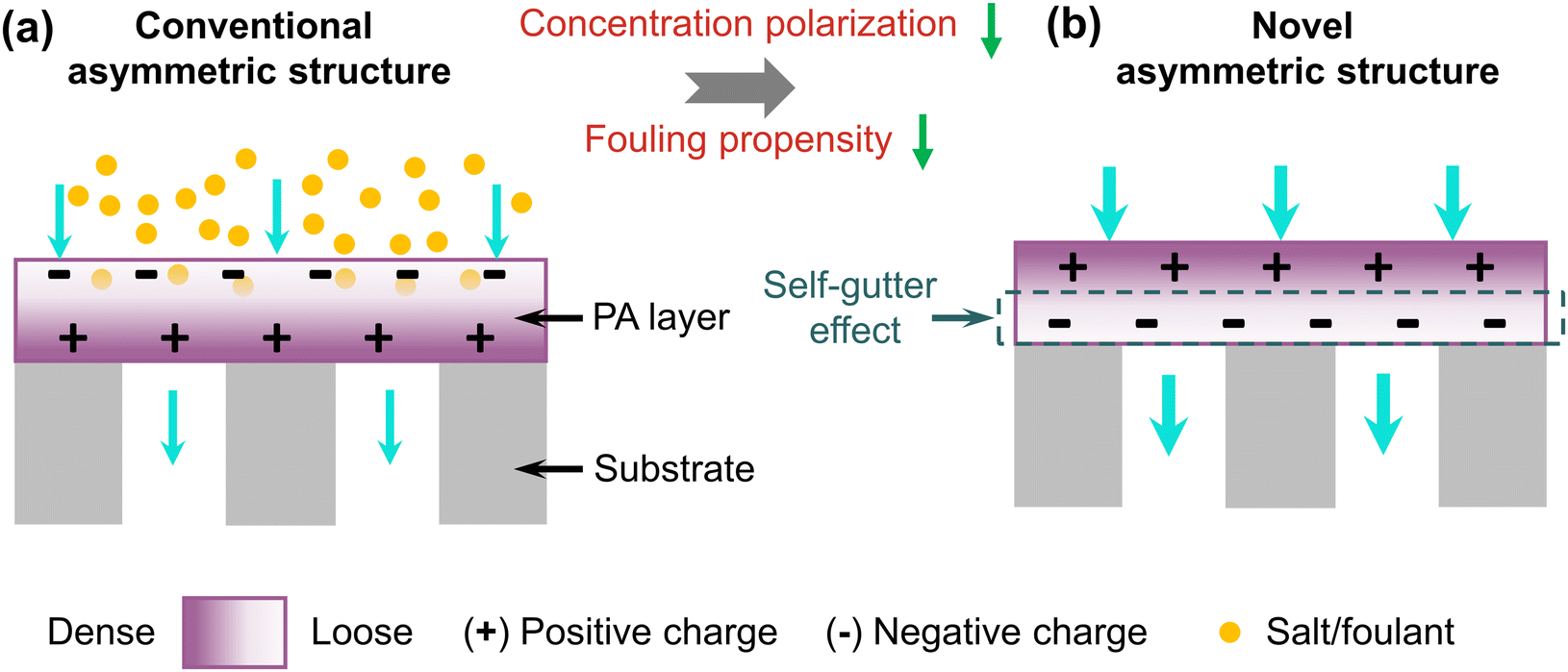 | ||
| Fig. 13 Schematic view of asymmetric polyamide membranes on top of a porous substrate where (a) shows the conventional asymmetric polyamide structure, and (b) shows the novel asymmetric polyamide structure. | ||
4. Implications and future perspectives
4.1. Implications of ultrathin membranes in real-field applications
Ultrathin membranes offer numerous advantages in real-field applications, with the potential to revolutionize industries such as water, chemical, and pharmaceutical sectors. These membranes feature high efficiency, low energy consumption,23 and low maintenance requirements, making them an ideal choice for many industries. Despite the potential advantages, the fabrication of ultrathin membranes for real-field applications may face challenges on the industrial scale. In particular, achieving the required rejection/selectivity may need a structure that is highly cross-linked and free from defects. In this regard, approaches such as electrospray,45,48,174 which intrinsically tend to produce a large number of defects, generally show lower rejections (Table 1) and are thus less preferred. In the future development of ultrathin membranes, it is crucial to emphasize on defect control and structural integrity for large-scale membrane productions. The development of novel emerging membrane materials and new fabrication techniques may further enhance their feasibility, fulfilling their application demands as potential alternatives to conventional membranes.4.2. Implications to other emerging membrane materials and their commercial scale viability
Even though many approaches are outlined for creating high-performance ultrathin polyamide-based TFC membranes, some of the strategies highlighted in Section 3.1.3 can be potentially relevant for other newly developed emerging materials to boost their separation performance by successfully decreasing the water transport path, lowering the hydraulic resistance and minimizing the funnel effect. For example, aquaporin-based biomimetic membranes (AQPs),175–177 aligned carbon nanotube (CNT)-based membranes,178,179 synthetically designed nanochannels,180–182 nanoporous graphene membranes (NPG),183,184 MOF/COF membranes,185,186 and 2D graphene-based membranes,187 all experience the aforementioned geometric restriction due to the substrate membrane. Therefore, minimizing the transport pathways by creating ultrathin membranes with crumpled morphology or introducing interlayers with different surface chemistry between these newly developed membranes and the substrate membranes can be a beneficial and adaptable way for customizing the performance of emerging membrane materials (Fig. 14). | ||
| Fig. 14 The plot demonstrates the comparison of the traditional TFC membrane, the ultrathin membrane with a crumpled structure, the ultrathin membrane with an interlayer, and newly emerging membrane materials in terms of their performance and commercial scale viability. The figure adopted with an upgraded evaluation framework similar to the one published by Pendergast et al. (ref. 188), Yang et al. (ref. 189), and Guo et al. (ref. 190). | ||
For industrial applications, large-scale roll-to-roll production of the newly designed ultrathin membranes and emerging membrane materials is of utmost importance. In Fig. 14, we have qualitatively plotted the performance and commercial scale feasibility comparison of the traditional membranes, the ultrathin membrane with a crumpled structure, the ultrathin membrane with an interlayer and several novel membrane materials.188–190 The vertical axis shows the (possible) membrane performance improvement with respect to water permeance, while the horizontal axis indicates the commercial viability based on scalable technology and fabrication expenses. Although newly developed membrane materials offer great separation performance, they often face challenges when it comes to large scale roll-to-roll manufacturing. As an example, graphene-based membranes may be produced at large scales, whereas other emerging membrane materials like AQPs,9 CNTs,9 nanoporous graphene (NPG),191 2D graphene-based187 membranes, and MOF185 membranes, pose challenges for commercial scale-up and thus demand highly specialized manufacturing techniques. Additionally, further research will be required in order to fully exploit the potential applications and technological viability of these membranes.
4.3. Utilization of ultrathin membranes in other applications
 | ||
| Fig. 15 Schematic presentation of the future perspectives and remaining challenges to fully unleash the effectiveness of new emerging membrane materials using novel fabrication protocols. The figure of the membrane module is adapted with permission from ref. 201, Copyright 2023, American Association for the Advancement of Science. | ||
5. Conclusions
The most recent research on ultrathin polyamide-based membranes, limitations, and potential solutions with future perspectives have been outlined here. As the top selective layer is crucial for the transportation of water or solvents, it is a promising approach for reducing the top selective layer's thickness in order to enhance the overall membrane performance. In this review, we provide a thorough investigation into the creation of ultrathin membranes by optimizing the interfacial polymerization process and employing a variety of novel fabrication methods. We critically assessed the drawbacks associated with ultrathin membranes resulting from the substrate membrane, and discussed, some potential strategies to enhance the performance of ultrathin polyamide membranes. We also explained how these strategies will improve the performance of the ultrathin membranes when utilized for both existing and newly developed membrane materials. A qualitative assessment of the performance and commercial scale feasibility of various traditional membranes and novel membrane materials is also presented. Overall, the primary focus for future research needs to be the scaling up of membrane production and the production of membrane modules for industrial purposes.Abbreviations
| A | Water permeance |
| AFM | Atomic force microscopy |
| Aobs | Observed or apparent water permeance |
| AQPs | Aquaporins |
| CNTs | Carbon nanotubes |
| COF | Covalent organic frameworks |
| CVD | Chemical vapor deposition |
| DLC | Diamond-like carbon |
| DMF | Dimethylformamide |
| DSC | Dual-layer slot coating |
| FO | Forward osmosis |
| GO | Graphene oxide |
| g-C3N4 | Graphitic carbon nitride |
| IP | Interfacial polymerization |
| K ideal | P Hw,PA or ideal/intrinsic water permeability of the polyamide layer |
| K ideal/lPA | Ideal water permeance of the freestanding film |
| LbL | Layer-by-layer |
| l eff | Effective water transport length |
| l PA | Thickness of the polyamide layer |
| MF | Microfiltration |
| mLbL | Molecular layer-by-layer |
| MOF | Metal–organic framework |
| MONs | Microporous organic nanotube |
| MPD | m-Phenylenediamine |
| n | Relative hydraulic water permeability |
| NF | Nanofiltration |
| NPG | Nanoporous graphene |
| OSN | Organic solvent nanofiltration |
| PA | Polyamide |
| PAA | Polyacrylic acid |
| PAN | Polyacrylonitrile |
| PCS | Phytate-coordinated substrate |
| PD/PDA | Polydopamine |
| PEI | Polyethylene imine |
| PES | Polyether sulfone |
| PIP | Piperazine |
| PSf | Polysulfone |
| PVA | Polyvinyl alcohol |
| RO | Reverse osmosis |
| SEM | Scanning electron microscope |
| SLS | Sodium lauryl sulfate |
| SWCNT | Single-walled carbon nanotubes |
| TAPB | 1,3,5-Tris(4-aminophenyl)benzene |
| TAPM | Tetrakis(4-aminophenyl)methane |
| TEM | Transmission electron microscope |
| TFC | Thin-film composite |
| TFNi | Interlayered thin-film nanocomposite |
| TMC | Trimesoyl chloride |
| TPMC | Tetraphenyl-methane-4,4′,4′′,4′′′-tetraacyl chloride |
| UF | Ultrafiltration |
| ZIF-8 | Zeolitic imidazolate framework |
| ε | Substrate porosity |
Conflicts of interest
There are no conflicts to declare.Acknowledgements
This study was supported by the General Research Fund (project no: 17201921 and 17206122) of the Research Grants Council of Hong Kong. This work was also partially supported by the Innovation and Technology Fund (project no: GHP/181/20GD) of the Hong Kong Special Administrative Region, China, and the RGC Senior Research Fellow Scheme from the Research Grants Council of the Hong Kong Special Administration Region, China (project no: SRFS2021-7S04). Publication was made possible in part by support from the HKU Libraries Open Access Author Fund sponsored by the HKU Libraries.References
- R. I. McDonald, P. Green, D. Balk, B. M. Fekete, C. Revenga, M. Todd and M. Montgomery, Proc. Natl. Acad. Sci. U. S. A., 2011, 108, 6312–6317 CrossRef CAS PubMed.
- P. H. Gleick, Proc. Natl. Acad. Sci. U. S. A., 2018, 115, 8863–8871 CrossRef CAS PubMed.
- M. Elimelech, J. Water Supply: Res. Technol. – AQUA, 2006, 55, 3–10 CrossRef.
- M. A. Shannon, P. W. Bohn, M. Elimelech, J. G. Georgiadis, B. J. Mariñas and A. M. Mayes, Nature, 2008, 452, 301–310 CrossRef CAS PubMed.
- E. Curcio and E. Drioli, Sep. Purif. Rev., 2005, 34, 35–86 CrossRef CAS.
- X. Zhou, F. Zhao, P. Zhang and G. Yu, ACS Mater. Lett., 2021, 3, 1112–1129 CrossRef CAS.
- C. Y. Tang, Z. Yang, H. Guo, J. J. Wen, L. D. Nghiem and E. Cornelissen, Environ. Sci. Technol., 2018, 52, 10215–10223 CrossRef CAS PubMed.
- M. Elimelech and W. A. Phillip, Science, 2011, 333, 712–717 CrossRef CAS PubMed.
- J. R. Werber, C. O. Osuji and M. Elimelech, Nat. Rev. Mater., 2016, 1, 1–15 Search PubMed.
- K. Wang, X. Wang, B. Januszewski, Y. Liu, D. Li, R. Fu, M. Elimelech and X. Huang, Chem. Soc. Rev., 2022, 51, 672–719 RSC.
- X. Lu and M. Elimelech, Chem. Soc. Rev., 2021, 50, 6290–6307 RSC.
- R. Zhang, Y. Liu, M. He, Y. Su, X. Zhao, M. Elimelech and Z. Jiang, Chem. Soc. Rev., 2016, 45, 5888–5924 RSC.
- P. Sarkar, S. Modak and S. Karan, Adv. Funct. Mater., 2021, 31, 2007054 CrossRef CAS.
- Y. Liang, Y. Zhu, C. Liu, K.-R. Lee, W.-S. Hung, Z. Wang, Y. Li, M. Elimelech, J. Jin and S. Lin, Nat. Commun., 2020, 11, 2015 CrossRef CAS PubMed.
- P. Sarkar, S. Modak, S. Ray, V. Adupa, K. A. Reddy and S. Karan, J. Mater. Chem. A, 2021, 9, 20714–20724 RSC.
- H. Peng, W. H. Zhang, W. S. Hung, N. Wang, J. Sun, K. R. Lee, Q. F. An, C. M. Liu and Q. Zhao, Adv. Mater., 2020, 32, 2001383 CrossRef CAS PubMed.
- B.-Q. Huang, Y.-J. Tang, Z.-X. Zeng, S.-M. Xue, C.-H. Ji and Z.-L. Xu, ACS Appl. Mater. Interfaces, 2020, 12, 35523–35531 CrossRef CAS PubMed.
- S. Karan, Z. Jiang and A. G. Livingston, Science, 2015, 348, 1347–1351 CrossRef CAS PubMed.
- Z. Wang, Z. Wang, S. Lin, H. Jin, S. Gao, Y. Zhu and J. Jin, Nat. Commun., 2018, 9, 2004 CrossRef PubMed.
- S. Han, J. Zhu, A. A. Uliana, D. Li, Y. Zhang, L. Zhang, Y. Wang, T. He and M. Elimelech, Nat. Commun., 2022, 13, 7954 CrossRef CAS PubMed.
- C. Zhao, Y. Zhang, Y. Jia, B. Li, W. Tang, C. Shang, R. Mo, P. Li, S. Liu and S. Zhang, Nat. Commun., 2023, 14, 1112 CrossRef CAS PubMed.
- R. Dai, H. Zhou, T. Wang, Z. Qiu, L. Long, S. Lin, C. Y. Tang and Z. Wang, Nat. Water, 2023, 1, 281–290 CrossRef.
- Z. Yang, C. Wu and C. Y. Tang, Water Res. X, 2023, 19, 100172 CrossRef CAS PubMed.
- D. Cohen-Tanugi, R. K. McGovern, S. H. Dave, J. H. Lienhard and J. C. Grossman, Energy Environ. Sci., 2014, 7, 1134–1141 RSC.
- J. Tian, H. Chang, S. Gao, Y. Zong, B. Van der Bruggen and R. Zhang, J. Membr. Sci., 2021, 634, 119450 CrossRef CAS.
- Z. Jiang, S. Karan and A. G. Livingston, Adv. Mater., 2018, 30, 1705973 CrossRef PubMed.
- S.-J. Park, W. Choi, S.-E. Nam, S. Hong, J. S. Lee and J.-H. Lee, J. Membr. Sci., 2017, 526, 52–59 CrossRef CAS.
- L. Paseta, C. Echaide-Górriz, C. Téllez and J. Coronas, Green Chem., 2021, 23, 2449–2456 RSC.
- W. Li, Z. Yang, W. Yang, H. Guo and C. Y. Tang, AIChE J., 2022, 68, e17517 CrossRef CAS.
- Y. Zhu, W. Xie, S. Gao, F. Zhang, W. Zhang, Z. Liu and J. Jin, Small, 2016, 12, 5034–5041 CrossRef CAS PubMed.
- S. Xue, C.-W. Lin, C. Ji, Y. Guo, L. Liu, Z. Yang, S. Zhao, X. Cai, Q. J. Niu and R. B. Kaner, Nano Lett., 2022, 22, 1039–1046 CrossRef CAS PubMed.
- Z. Zhou, Y. Hu, C. Boo, Z. Liu, J. Li, L. Deng and X. An, Environ. Sci. Technol. Lett., 2018, 5, 243–248 CrossRef CAS.
- R. Dai, J. Li and Z. Wang, Adv. Colloid Interface Sci., 2020, 282, 102204 CrossRef CAS PubMed.
- S. Gao, Y. Zhu, Y. Gong, Z. Wang, W. Fang and J. Jin, ACS Nano, 2019, 13, 5278–5290 CrossRef CAS PubMed.
- G. Gong, P. Wang, Z. Zhou and Y. Hu, ACS Appl. Mater. Interfaces, 2019, 11, 7349–7356 CrossRef CAS PubMed.
- Z. Zhang, X. Shi, R. Wang, A. Xiao and Y. Wang, Chem. Sci., 2019, 10, 9077–9083 RSC.
- X. You, K. Xiao, H. Wu, Y. Li, R. Li, J. Yuan, R. Zhang, Z. Zhang, X. Liang, J. Shen and Z. Jiang, Iscience, 2021, 24, 102369 CrossRef CAS PubMed.
- L. Shen, R. Cheng, M. Yi, W.-S. Hung, S. Japip, L. Tian, X. Zhang, S. Jiang, S. Li and Y. Wang, Nat. Commun., 2022, 13, 500 CrossRef CAS PubMed.
- H. Qian, S. Li, J. Zheng and S. Zhang, Langmuir, 2012, 28, 17803–17810 CrossRef CAS PubMed.
- J. E. Gu, S. Lee, C. M. Stafford, J. S. Lee, W. Choi, B. Y. Kim, K. Y. Baek, E. P. Chan, J. Y. Chung and J. Bang, Adv. Mater., 2013, 25, 4778–4782 CrossRef CAS PubMed.
- W. Choi, J.-E. Gu, S.-H. Park, S. Kim, J. Bang, K.-Y. Baek, B. Park, J. S. Lee, E. P. Chan and J.-H. Lee, ACS Nano, 2015, 9, 345–355 CrossRef CAS PubMed.
- X. Shui, J. Li, M. Zhang, C. Fang and L. Zhu, J. Membr. Sci., 2021, 628, 119249 CrossRef CAS.
- Z. Zhou, S. Zhou, X. Cheng, W. Liu, R. Wu, J. Wang, B. Liu, J. Zhu, B. Van der Bruggen and Y. Zhang, Sep. Purif. Technol., 2022, 288, 120648 CrossRef CAS.
- Y. Liu, H. Wu, H. Zhang, J. Wang and Z. Wang, Vacuum, 2023, 207, 111645 CrossRef CAS.
- X.-H. Ma, Z. Yang, Z.-K. Yao, H. Guo, Z.-L. Xu and C. Y. Tang, Environ. Sci. Technol. Lett., 2018, 5, 117–122 CrossRef CAS.
- M. R. Chowdhury, J. Steffes, B. D. Huey and J. R. McCutcheon, Science, 2018, 361, 682–686 CrossRef CAS PubMed.
- S. Yang, J. Wang, L. Fang, H. Lin, F. Liu and C. Y. Tang, J. Membr. Sci., 2020, 602, 117971 CrossRef.
- J. Chen, J. Zhang, X. Wu, X. Cui, W. Li, H. Zhang, J. Wang, X.-Z. Cao and P. Zhang, J. Mater. Chem. A, 2020, 8, 9160–9167 RSC.
- S.-J. Park, W.-G. Ahn, W. Choi, S.-H. Park, J. S. Lee, H. W. Jung and J.-H. Lee, J. Mater. Chem. A, 2017, 5, 6648–6655 RSC.
- S.-J. Park and J.-H. Lee, J. Membr. Sci., 2020, 614, 118449 CrossRef CAS.
- S. Badalov and C. J. Arnusch, J. Membr. Sci., 2016, 515, 79–85 CrossRef CAS.
- C. Wang, M. J. Park, R. R. Gonzales, S. Phuntsho, H. Matsuyama, E. Drioli and H. K. Shon, J. Membr. Sci., 2022, 655, 120582 CrossRef CAS.
- M. J. Park, C. Wang, R. R. Gonzales, S. Phuntsho, H. Matsuyama, E. Drioli and H. K. Shon, Desalination, 2022, 541, 116027 CrossRef CAS.
- C. Jiang, L. Zhang, P. Li, H. Sun, Y. Hou and Q. J. Niu, ACS Appl. Mater. Interfaces, 2020, 12, 25304–25315 CrossRef CAS PubMed.
- F. Wang, Z. Yang and C. Y. Tang, ACS EST Engg., 2022, 2, 2023–2033 CrossRef CAS.
- S. Gao, D. Wang, W. Fang and J. Jin, Adv. Mater. Technol., 2020, 5, 1901069 CrossRef CAS.
- S. Zhang, L. Shen, H. Deng, Q. Liu, X. You, J. Yuan, Z. Jiang and S. Zhang, Adv. Mater., 2022, 34, 2108457 CrossRef CAS PubMed.
- P. W. Morgan, Condensation polymers: by interfacial and solution methods, Interscience Publishers, New York, 1965 Search PubMed.
- E. L. Wittbecker and P. W. Morgan, J. Polym. Sci., 1959, 40, 289–297 CrossRef CAS.
- P. W. Morgan and S. L. Kwolek, J. Polym. Sci., 1959, 40, 299–327 CrossRef CAS.
- S. Zhou, L. Long, Z. Yang, S. L. So, B. Gan, H. Guo, S.-P. Feng and C. Y. Tang, Environ. Sci. Technol., 2022, 56, 10279–10288 CrossRef CAS PubMed.
- L. Lin, C. Feng, R. Lopez and O. Coronell, J. Membr. Sci., 2016, 498, 167–179 CrossRef CAS.
- D. Poncelet, B. P. De Smet and R. J. Neufeld, J. Membr. Sci., 1990, 50, 249–267 CrossRef CAS.
- G.-Y. Chai and W. B. Krantz, J. Membr. Sci., 1994, 93, 175–192 CrossRef CAS.
- L. Danicher, P. Gramain, Y. Frère and A. Le Calvé, React. Funct. Polym., 1999, 42, 111–125 CrossRef CAS.
- A. N. Storey, W. Zhang, J. F. Douglas and F. W. Starr, Macromolecules, 2020, 53, 9654–9664 CrossRef CAS.
- K. Takamura, M. Koishi and T. Kondo, J. Pharm. Sci., 1973, 62, 610–612 CrossRef CAS PubMed.
- K. Tiwari, S. Modak, P. Sarkar, S. Ray, V. Adupa, K. A. Reddy, S. K. Pramanik, A. Das and S. Karan, iScience, 2022, 25, 104027 CrossRef CAS PubMed.
- P. Sarkar, T. Sarkar, H. Singh, B. Sutariya, S. Ray, A. Das, S. K. Pramanik and S. Karan, J. Mater. Chem. A, 2023, 11, 14390–14403 RSC.
- F. MacRitchie, Trans. Faraday Soc., 1969, 65, 2503–2507 RSC.
- P. Zhang, F. Zhang, C. Zhao, S. Wang, M. Liu and L. Jiang, Angew. Chem., 2016, 128, 3679–3683 CrossRef.
- J. Ji, J. M. Dickson, R. F. Childs and B. E. Mccarry, Macromolecules, 2000, 33, 624–633 CrossRef CAS.
- L. Janssen and K. Te Nijenhuis, J. Membr. Sci., 1992, 65, 59–68 CrossRef CAS.
- Y. Zhang, N. E. Benes and R. G. H. Lammertink, Lab Chip, 2015, 15, 575–580 RSC.
- R. Arshady, J. Microencapsulation, 1989, 6, 13–28 CrossRef CAS PubMed.
- J. J. Richardson, M. Björnmalm and F. Caruso, Science, 2015, 348, aaa2491 CrossRef PubMed.
- X. Song, S. Qi, C. Y. Tang and C. Gao, J. Membr. Sci., 2017, 540, 10–18 CrossRef CAS.
- J. J. Richardson, J. Cui, M. Bjornmalm, J. A. Braunger, H. Ejima and F. Caruso, Chem. Rev., 2016, 116, 14828–14867 CrossRef CAS PubMed.
- Y. Li, X. Wang and J. Sun, Chem. Soc. Rev., 2012, 41, 5998–6009 RSC.
- A. Qi, P. Chan, J. Ho, A. Rajapaksa, J. Friend and L. Yeo, ACS Nano, 2011, 5, 9583–9591 CrossRef CAS PubMed.
- G. Decher, Science, 1997, 277, 1232–1237 CrossRef CAS.
- S. U. Hong, R. Malaisamy and M. L. Bruening, J. Membr. Sci., 2006, 283, 366–372 CrossRef CAS.
- A. El-Hashani, A. Toutianoush and B. Tieke, J. Membr. Sci., 2008, 318, 65–70 CrossRef CAS.
- C. Wang, M. J. Park, H. Yu, H. Matsuyama, E. Drioli and H. K. Shon, J. Membr. Sci., 2022, 120926 CrossRef CAS.
- V. Chernikova, O. Shekhah and M. Eddaoudi, ACS Appl. Mater. Interfaces, 2016, 8, 20459–20464 CrossRef CAS PubMed.
- R. Weitz, L. Harnau, S. Rauschenbach, M. Burghard and K. Kern, Nano Lett., 2008, 8, 1187–1191 CrossRef CAS PubMed.
- Y. Zhang, C. A. D’Ambra, R. Katsumata, R. L. Burns, M. H. Somervell, R. A. Segalman, C. J. Hawker and C. M. Bates, ACS Appl. Mater. Interfaces, 2019, 11, 21177–21183 CrossRef CAS PubMed.
- P. A. Chiarelli, M. S. Johal, J. L. Casson, J. B. Roberts, J. M. Robinson and H. L. Wang, Adv. Mater., 2001, 13, 1167–1171 CrossRef CAS.
- X. Kang, X. Liu, J. Liu, Y. Wen, J. Qi and X. Li, Appl. Surf. Sci., 2020, 508, 145198 CrossRef CAS.
- A. Jaworek and A. T. Sobczyk, J. Electrostat., 2008, 66, 197–219 CrossRef CAS.
- R. Bernstein, C. E. Singer, S. P. Singh, C. Mao and C. J. Arnusch, J. Membr. Sci., 2018, 548, 73–80 CrossRef CAS.
- S. Badalov, Y. Oren and C. J. Arnusch, J. Membr. Sci., 2015, 493, 508–514 CrossRef CAS.
- M. Fathizadeh, H. N. Tien, K. Khivantsev, J.-T. Chen and M. Yu, J. Mater. Chem. A, 2017, 5, 20860–20866 RSC.
- H. S. Ji, W.-G. Ahn, I. Kwon, J. Nam and H. W. Jung, Chem. Eng. Sci., 2016, 143, 122–129 CrossRef CAS.
- S. D. Taylor and A. N. Hrymak, Chem. Eng. Sci., 1999, 54, 909–918 CrossRef CAS.
- J. Nam and M. S. Carvalho, J. Fluid Mech., 2009, 631, 397–417 CrossRef.
- N. A. Khan, R. Zhang, H. Wu, J. Shen, J. Yuan, C. Fan, L. Cao, M. A. Olson and Z. Jiang, J. Am. Chem. Soc., 2020, 142, 13450–13458 CrossRef CAS PubMed.
- D. Yadav, S. Karki, M. B. Gohain and P. G. Ingole, Chem. Eng. J., 2023, 472, 144940 CrossRef CAS.
- S. Karki and P. G. Ingole, Chem. Eng. J., 2022, 446, 137303 CrossRef CAS.
- J. Robertson, Mater. Sci. Eng., R, 2002, 37, 129–281 CrossRef.
- X.-D. Pan, E. Maydell, R. Milne and D. Fabian, Vacuum, 1990, 41, 1360–1363 CrossRef CAS.
- S. Karan, S. Samitsu, X. Peng, K. Kurashima and I. Ichinose, Science, 2012, 335, 444–447 CrossRef CAS PubMed.
- J. Zhu, J. Hou, R. Zhang, S. Yuan, J. Li, M. Tian, P. Wang, Y. Zhang, A. Volodin and B. Van der Bruggen, J. Mater. Chem. A, 2018, 6, 15701–15709 RSC.
- W. B. Jensen, J. Chem. Educ., 2006, 83, 1283 CrossRef CAS.
- A. R. Madaria, A. Kumar, F. N. Ishikawa and C. Zhou, Nano Res., 2010, 3, 564–573 CrossRef CAS.
- K.-G. Zhou, K. Vasu, C. Cherian, M. Neek-Amal, J. C. Zhang, H. Ghorbanfekr-Kalashami, K. Huang, O. Marshall, V. Kravets and J. Abraham, Nature, 2018, 559, 236–240 CrossRef CAS PubMed.
- B.-S. Kong, J. Geng and H.-T. Jung, Chem. Commun., 2009, 2174–2176 RSC.
- A. Achari, S. Sahana and M. Eswaramoorthy, Energy Environ. Sci., 2016, 9, 1224–1228 RSC.
- D. Wang, Z. Wang, L. Wang, L. Hu and J. Jin, Nanoscale, 2015, 7, 17649–17652 RSC.
- S. Liu, R. Wang, M. Liu, J. Luo, X. Jin, J. Sun and L. Gao, J. Mater. Chem. A, 2014, 2, 4598–4604 RSC.
- X. Song, Y. Zhang, H. M. Abdel-Ghafar, E.-S. A. Abdel-Aal, M. Huang, S. Gul and H. Jiang, Chem. Eng. J., 2021, 412, 128607 CrossRef CAS.
- J.-J. Wang, H.-C. Yang, M.-B. Wu, X. Zhang and Z.-K. Xu, J. Mater. Chem. A, 2017, 5, 16289–16295 RSC.
- Y. Wen, X. Zhang, X. Li, Z. Wang and C. Y. Tang, ACS Appl. Nano Mater., 2020, 3, 9238–9248 CrossRef.
- C.-Y. Zhu, H.-N. Li, J. Yang, J.-J. Li, J.-R. Ye and Z.-K. Xu, J. Membr. Sci., 2020, 616, 118557 CrossRef CAS.
- S. Wu, F. Wang, S. Zhou, L. Long, Z. Yang and C. Y. Tang, Sep. Purif. Technol., 2022, 297, 121547 CrossRef CAS.
- X.-H. Ma, Z.-K. Yao, Z. Yang, H. Guo, Z.-L. Xu, C. Y. Tang and M. Elimelech, Environ. Sci. Technol. Lett., 2018, 5, 123–130 CrossRef CAS.
- Z. Tan, S. Chen, X. Peng, L. Zhang and C. Gao, Science, 2018, 360, 518–521 CrossRef CAS PubMed.
- Y. Ren, J. Zhu, S. Cong, J. Wang, B. Van der Bruggen, J. Liu and Y. Zhang, J. Membr. Sci., 2019, 585, 19–28 CrossRef CAS.
- B. Yuan, S. Zhao, P. Hu, J. Cui and Q. J. Niu, Nat. Commun., 2020, 11, 6102 CrossRef CAS PubMed.
- Z. Zhai, N. Zhao, W. Dong, P. Li, H. Sun and Q. J. Niu, ACS Appl. Mater. Interfaces, 2019, 11, 12871–12879 CrossRef CAS PubMed.
- C. Li, S. Li, L. Tian, J. Zhang, B. Su and M. Z. Hu, J. Membr. Sci., 2019, 572, 520–531 CrossRef CAS.
- M. Hu and B. Mi, Environ. Sci. Technol., 2013, 47, 3715–3723 CrossRef CAS PubMed.
- Z. Yang, H. Guo, Z.-K. Yao, Y. Mei and C. Y. Tang, Environ. Sci. Technol., 2019, 53, 5301–5308 CrossRef CAS PubMed.
- L.-X. Dong, X.-C. Huang, Z. Wang, Z. Yang, X.-M. Wang and C. Y. Tang, Sep. Purif. Technol., 2016, 166, 230–239 CrossRef CAS.
- H. Zhang, X.-Y. Gong, W.-X. Li, X.-H. Ma, C. Y. Tang and Z.-L. Xu, J. Membr. Sci., 2020, 616, 118605 CrossRef CAS.
- J. Wang, Y. Wang, J. Zhu, Y. Zhang, J. Liu and B. Van der Bruggen, J. Membr. Sci., 2017, 533, 279–288 CrossRef CAS.
- S. Wang, Z. Yi, X. Zhao, Y. Zhou and C. Gao, RSC Adv., 2017, 7, 26136–26144 RSC.
- W. Gai, Y. Zhang, Q. Zhao and T.-S. Chung, J. Membr. Sci., 2021, 620, 118952 CrossRef CAS.
- Y. Xu, W. Zhang, Z. Li, L. Shen, R. Li, M. Zhang, Y. Jiao, H. Lin and C. Y. Tang, J. Mater. Chem. A, 2022, 10, 16430–16438 RSC.
- F.-Y. Zhao, Q.-F. An, Y.-L. Ji and C.-J. Gao, J. Membr. Sci., 2015, 492, 412–421 CrossRef CAS.
- H. Shen, S. Wang, H. Xu, Y. Zhou and C. Gao, J. Membr. Sci., 2018, 565, 145–156 CrossRef CAS.
- Z. Yang, P.-F. Sun, X. Li, B. Gan, L. Wang, X. Song, H.-D. Park and C. Y. Tang, Environ. Sci. Technol., 2020, 54, 15563–15583 CrossRef CAS PubMed.
- X. Zhu, X. Cheng, X. Luo, Y. Liu, D. Xu, X. Tang, Z. Gan, L. Yang, G. Li and H. Liang, Environ. Sci. Technol., 2020, 54, 6365–6374 CrossRef CAS PubMed.
- G. M. Geise, D. R. Paul and B. D. Freeman, Prog. Polym. Sci., 2014, 39, 1–42 CrossRef CAS.
- L. E. Peng, Z. Yang, L. Long, S. Zhou, H. Guo and C. Y. Tang, J. Membr. Sci., 2022, 641, 119871 CrossRef CAS.
- H. Lonsdale, R. Riley, C. Lyons and D. Carosella Jr, Membrane Processes in Industry and Biomedicine, Plenum Press, 1971 Search PubMed.
- L. Long, C. Wu, Z. Yang and C. Y. Tang, Environ. Sci. Technol., 2022, 56, 2656–2664 CrossRef CAS PubMed.
- G. Z. Ramon, M. C. Wong and E. M. Hoek, J. Membr. Sci., 2012, 415, 298–305 CrossRef.
- M. Kattula, K. Ponnuru, L. Zhu, W. Jia, H. Lin and E. P. Furlani, Sci. Rep., 2015, 5, 15016 CrossRef PubMed.
- S. Shao, F. Zeng, L. Long, X. Zhu, L. E. Peng, F. Wang, Z. Yang and C. Y. Tang, Environ. Sci. Technol., 2022, 56, 12811–12827 CrossRef CAS PubMed.
- Q. Gan, C. Wu, L. Long, L. E. Peng, Z. Yang, H. Guo and C. Y. Tang, Environ. Sci. Technol., 2023, 57, 2548–2556 CrossRef CAS PubMed.
- Z. Yang, Y. Wu, H. Guo, X.-H. Ma, C.-E. Lin, Y. Zhou, B. Cao, B.-K. Zhu, K. Shih and C. Y. Tang, J. Membr. Sci., 2017, 544, 351–358 CrossRef CAS.
- J. Yuan, M. Wu, H. Wu, Y. Liu, X. You, R. Zhang, Y. Su, H. Yang, J. Shen and Z. Jiang, J. Mater. Chem. A, 2019, 7, 25641–25649 RSC.
- P.-F. Sun, P. Sarkar, E.-T. Yun, J. H. Lee, C. Y. Tang and H.-D. Park, J. Membr. Sci., 2023, 121804 CrossRef CAS.
- G. Lai, W. Lau, P. Goh, Y. Tan, B. Ng and A. Ismail, Arab. J. Chem., 2019, 12, 75–87 CrossRef CAS.
- P.-F. Sun, Z. Yang, X. Song, J. H. Lee, C. Y. Tang and H.-D. Park, Environ. Sci. Technol., 2021, 55, 13219–13230 CAS.
- D. Xu, X. Zhu, X. Luo, Y. Guo, Y. Liu, L. Yang, X. Tang, G. Li and H. Liang, Environ. Sci. Technol., 2020, 55, 1270–1278 CrossRef PubMed.
- Z. Yang, Z.-w Zhou, H. Guo, Z. Yao, X.-h Ma, X. Song, S.-P. Feng and C. Y. Tang, Environ. Sci. Technol., 2018, 52, 9341–9349 CrossRef CAS PubMed.
- C. Jiang, L. Tian, Z. Zhai, Y. Shen, W. Dong, M. He, Y. Hou and Q. J. Niu, J. Membr. Sci., 2019, 589, 117244 CrossRef CAS.
- Z. Yang, F. Wang, H. Guo, L. E. Peng, X.-H. Ma, X.-X. Song, Z. Wang and C. Y. Tang, Environ. Sci. Technol., 2020, 54, 11611–11621 CrossRef CAS PubMed.
- G. Han, S. Zhang, X. Li, N. Widjojo and T.-S. Chung, Chem. Eng. Sci., 2012, 80, 219–231 CrossRef CAS.
- T. Wang, J. Wang, Z. Zhao, X. Zheng, J. Li, H. Liu and Z. Zhao, Ind. Eng. Chem. Res., 2021, 60, 14868–14883 CrossRef CAS.
- J. Liu, T. Huang, R. Ji, Z. Wang, C. Y. Tang and J. O. Leckie, Environ. Sci. Technol., 2020, 54, 12703–12712 CrossRef CAS PubMed.
- H. Guo, Y. Deng, Z. Tao, Z. Yao, J. Wang, C. Lin, T. Zhang, B. Zhu and C. Y. Tang, Environ. Sci. Technol. Lett., 2016, 3, 332–338 CrossRef CAS.
- H. Guo, Z. Yao, Z. Yang, X. Ma, J. Wang and C. Y. Tang, Environ. Sci. Technol., 2017, 51, 12638–12643 CrossRef CAS PubMed.
- H. Guo, Y. Deng, Z. Yao, Z. Yang, J. Wang, C. Lin, T. Zhang, B. Zhu and C. Y. Tang, Water Res., 2017, 121, 197–203 CrossRef CAS PubMed.
- K. A. Lundy and I. Cabasso, Ind. Eng. Chem. Res., 1989, 28, 742–756 CrossRef CAS.
- J. Lopez, S. Matson, J. Marchese and J. Quinn, J. Membr. Sci., 1986, 27, 301–325 CrossRef CAS.
- J. Wijmans and P. Hao, J. Membr. Sci., 2015, 494, 78–85 CrossRef CAS.
- B. Wu, N. Wang, J.-H. Lei, Y. Shen and Q.-F. An, J. Membr. Sci., 2022, 643, 120050 CrossRef CAS.
- X. Zhu, X. Zhang, J. Li, X. Luo, D. Xu, D. Wu, W. Wang, X. Cheng, G. Li and H. Liang, J. Membr. Sci., 2021, 635, 119536 CrossRef CAS.
- H. Lan, Y. Zhai, K. Chen, Z. Zhai, C. Jiang, P. Li, Y. Hou and Q. J. Niu, Separ. Purif. Technol., 2022, 290, 120781 CrossRef CAS.
- G. M. Geise, Science, 2021, 371, 31–32 CrossRef CAS PubMed.
- T. E. Culp, B. Khara, K. P. Brickey, M. Geitner, T. J. Zimudzi, J. D. Wilbur, S. D. Jons, A. Roy, M. Paul and B. Ganapathysubramanian, Science, 2021, 371, 72–75 CrossRef CAS PubMed.
- C. L. Ritt, J. R. Werber, M. Wang, Z. Yang, Y. Zhao, H. J. Kulik and M. Elimelech, Proc. Natl. Acad. Sci. U. S. A., 2020, 117, 30191–30200 CrossRef CAS PubMed.
- A. E. Childress and M. Elimelech, Environ. Sci. Technol., 2000, 34, 3710–3716 CrossRef CAS.
- J. Luo and Y. Wan, J. Membr. Sci., 2013, 438, 18–28 CrossRef CAS.
- R. Epsztein, E. Shaulsky, N. Dizge, D. M. Warsinger and M. Elimelech, Environ. Sci. Technol., 2018, 52, 4108–4116 CrossRef CAS PubMed.
- W. D. Mulhearn, V. P. Oleshko and C. M. Stafford, J. Membr. Sci., 2021, 618, 118637 CrossRef CAS PubMed.
- S.-J. Park, M.-S. Lee, M. E. Kilic, J. Ryu, H. Park, Y. I. Park, H. Kim, K.-R. Lee and J.-H. Lee, Nano Lett., 2023, 23, 4822–4829 CrossRef CAS PubMed.
- Q. Shen, Q. Song, Z. Mai, K.-R. Lee, T. Yoshioka, K. Guan, R. R. Gonzales and H. Matsuyama, Sci. Adv., 2023, 9, eadf6122 CrossRef CAS PubMed.
- Y. Gao, Y. Zhao, X.-M. Wang, C. Tang and X. Huang, Environ. Sci. Technol., 2022, 56, 14038–14047 CrossRef CAS PubMed.
- B. Gan, S. Qi, X. Song, Z. Yang, C. Y. Tang, X. Cao, Y. Zhou and C. Gao, J. Membr. Sci., 2020, 612, 118402 CrossRef CAS.
- S. Huang, J. Mansouri, P. Le-Clech, G. Leslie, C. Y. Tang and A. G. Fane, J. Membr. Sci., 2022, 646, 120248 CrossRef CAS.
- C. J. Porter, J. R. Werber, M. Zhong, C. J. Wilson and M. Elimelech, ACS Nano, 2020, 14, 10894–10916 CrossRef CAS PubMed.
- H. Sui, B.-G. Han, J. K. Lee, P. Walian and B. K. Jap, Nature, 2001, 414, 872–878 CrossRef CAS PubMed.
- M. Wang, Z. Wang, X. Wang, S. Wang, W. Ding and C. Gao, Environ. Sci. Technol., 2015, 49, 3761–3768 CrossRef CAS PubMed.
- J. K. Holt, H. G. Park, Y. Wang, M. Stadermann, A. B. Artyukhin, C. P. Grigoropoulos, A. Noy and O. Bakajin, Science, 2006, 312, 1034–1037 CrossRef CAS PubMed.
- B. Corry, J. Phys. Chem. B, 2008, 112, 1427–1434 CrossRef CAS PubMed.
- Y.-x Shen, W. Si, M. Erbakan, K. Decker, R. De Zorzi, P. O. Saboe, Y. J. Kang, S. Majd, P. J. Butler and T. Walz, Proc. Natl. Acad. Sci. U. S. A., 2015, 112, 9810–9815 CrossRef CAS PubMed.
- X.-B. Hu, Z. Chen, G. Tang, J.-L. Hou and Z.-T. Li, J. Am. Chem. Soc., 2012, 134, 8384–8387 CrossRef CAS PubMed.
- X. Zhou, G. Liu, K. Yamato, Y. Shen, R. Cheng, X. Wei, W. Bai, Y. Gao, H. Li and Y. Liu, Nat. Commun., 2012, 3, 949 CrossRef PubMed.
- D. Cohen-Tanugi and J. C. Grossman, Nano Lett., 2012, 12, 3602–3608 CrossRef CAS PubMed.
- D. Cohen-Tanugi, L.-C. Lin and J. C. Grossman, Nano Lett., 2016, 16, 1027–1033 CrossRef CAS PubMed.
- S. Cong, Y. Yuan, J. Wang, Z. Wang, F. Kapteijn and X. Liu, J. Am. Chem. Soc., 2021, 143, 20055–20058 CrossRef CAS PubMed.
- C. Zhang, B.-H. Wu, M.-Q. Ma, Z. Wang and Z.-K. Xu, Chem. Soc. Rev., 2019, 48, 3811–3841 RSC.
- L. Huang, M. Zhang, C. Li and G. Shi, J. Phys. Chem. Lett., 2015, 6, 2806–2815 CrossRef CAS PubMed.
- M. M. Pendergast and E. M. Hoek, Energy Environ. Sci., 2011, 4, 1946–1971 RSC.
- Z. Yang, X.-H. Ma and C. Y. Tang, Desalination, 2018, 434, 37–59 CrossRef CAS.
- H. Guo, R. Dai, M. Xie, L. E. Peng, Z. Yao, Z. Yang, L. D. Nghiem, S. A. Snyder, Z. Wang and C. Y. Tang, Environ. Sci. Technol. Lett., 2022, 9, 247–257 CrossRef CAS.
- J. Kang, Y. Ko, J. P. Kim, J. Y. Kim, J. Kim, O. Kwon, K. C. Kim and D. W. Kim, Nat. Commun., 2023, 14, 901 CrossRef CAS PubMed.
- P. Marchetti, M. F. Jimenez Solomon, G. Szekely and A. G. Livingston, Chem. Rev., 2014, 114, 10735–10806 CrossRef CAS PubMed.
- G. M. Shi, Y. Feng, B. Li, H. M. Tham, J.-Y. Lai and T.-S. Chung, Prog. Polym. Sci., 2021, 123, 101470 CrossRef CAS.
- Z. Jiang, R. Dong, A. M. Evans, N. Biere, M. A. Ebrahim, S. Li, D. Anselmetti, W. R. Dichtel and A. G. Livingston, Nature, 2022, 609, 58–64 CrossRef CAS PubMed.
- S. Li, R. Dong, V.-E. Musteata, J. Kim, N. D. Rangnekar, J. Johnson, B. D. Marshall, S. Chisca, J. Xu and S. Hoy, Science, 2022, 377, 1555–1561 CrossRef CAS PubMed.
- M. F. Jimenez-Solomon, Q. Song, K. E. Jelfs, M. Munoz-Ibanez and A. G. Livingston, Nat. Mater., 2016, 15, 760–767 CrossRef CAS PubMed.
- R. S. K. Valappil, N. Ghasem and M. Al-Marzouqi, J. Ind. Eng. Chem., 2021, 98, 103–129 CrossRef.
- T. Zhu, Q. Xia, J. Zuo, S. Liu, X. Yu and Y. Wang, Adv. Membr., 2021, 1, 100008 CrossRef.
- F. Wiesler and R. Sodaro, Ultrapure Water, 1996, 13, 53–56 CAS.
- Y. Zhao, N. Li, J. Shi, Y. Xia, B. Zhu, R. Shao, C. Min, Z. Xu and H. Deng, Sep. Purif. Technol., 2022, 286, 120419 CrossRef CAS.
- J. R. McCutcheon and M. S. Mauter, Science, 2023, 380, 242–244 CrossRef CAS PubMed.
| This journal is © The Royal Society of Chemistry 2024 |