
Nanotechnologies in ceramic electrochemical cells
Jiafeng
Cao
 *a,
Yuexia
Ji
a and
Zongping
Shao
*b
*a,
Yuexia
Ji
a and
Zongping
Shao
*b
aSchool of Microelectronics and Data Science, Anhui University of Technology, Maanshan 243032, Anhui, China. E-mail: jiafengcao@126.com
bWA School of Mines: Minerals, Energy and Chemical Engineering, Curtin University, Perth, Western Australia 6102, Australia. E-mail: zongping.shao@curtin.edu.au
First published on 15th December 2023
Abstract
Although they are emerging technologies for achieving high-efficiency and green and eco-friendly energy conversion, ceramic electrochemical cells (CECs), i.e. solid oxide electrolysis cells (SOECs) and fuel cells (SOFCs), are still fundamentally limited by their inferior catalytic activities at low temperature, poor thermo-mechanical stability, high material cost, etc. The materials used in electrolytes and electrodes, which are the most important components in CECs, are highly associated with the cell performances. Therefore, rational design of electrolytes and electrodes with excellent catalytic activities and high stabilities at relatively low cost is a meaningful and valuable approach for the development of CECs. Nanotechnology is a powerful tool for improving the material performances in CECs owing to the favourable effects induced by the nanocrystallization of electrolytes and electrodes. Herein, a relatively comprehensive review on the nanotechnologies implemented in CECs is conducted. The working principles of CECs and the corresponding challenges were first presented, followed by the comprehensive insights into the working mechanisms of nanocrystalline materials in CECs. Then, systematic summarization and analyses of the commonly used nano-engineering strategies in the fabrication of CEC materials, including physical and chemical methods, were provided. In addition, the frontiers in the research of advanced electrolyte and electrode materials were discussed with a special emphasis on the modified electrochemical properties derived from nanotechnologies. Finally, the bottlenecks and the promising breakthroughs in nanotechnologies were highlighted in the direction of providing useful references for rational design of nanomaterials for CECs.
 Jiafeng Cao | Jiafeng Cao is currently an associate professor at Anhui University of Technology. He received his PhD degree from University of Science and Technology of China (USTC) in 2017. In 2019, he worked with Prof. Zongping Shao as a visiting scholar at Curtin University. His research activities mainly focus on solid oxide fuel cells and electrolysis cells. |
 Yuexia Ji | Yuexia Ji is an associate professor at Anhui University of Technology. She received her PhD degree from University of Chinese Academy of Sciences in 2013. Her research interests focus on the design, synthesis and optimization of electrolyte and electrode materials for ceramic electrochemical cells. |
 Zongping Shao | Zongping Shao is a John Curtin Distinguished Professor at Curtin University, Australia. He obtained his PhD degree from Dalian Institute of Chemical Physics, Chinese Academy of Sciences in 2000. His research interests mainly include ceramic electrochemical cells, lithium-ion batteries, supercapacitors, solar cells, and low-temperature energy conversion devices. |
1. Introduction
Since the first industrial revolution that occurred more than two centuries ago, fossil fuels have always been the main energy sources for human beings, which contribute significantly to the quick progress of modern human civilization.1 However, due to their non-renewable, impurity-containing and carbon-rich nature, the excessive use of fossil fuels has brought serious concerns about the sustainability of energy supply and has led to greenhouse effects and environmental pollution. Actually, excessive consumption of traditional fossil energy has aggravated harmful gas or carbon emissions, such as SOx, NOx, and CO2, leading to acid rain and greenhouse effects.2 A worldwide consensus has been reached in reducing fossil energy consumption and carbon dioxide emissions and it has become an irresistible historical trend. For achieving this, ceramic electrochemical cells, i.e. solid oxide electrolysis cells (SOECs) and their reversible mode, solid oxide fuel cells (SOFCs), may play a crucial role in this transition due to a variety of their favorable characteristics, such as their green and climate-friendly (when fed with H2O/H2) nature, high efficiency (combined with heat engine),3 reversiblility,4 flexibility (both in fuel selection and architecture integration),5,6 and noiseless and theoretically economic features,7 as compared to other energy storage/conversion devices, for instance, lithium-ion batteries (LIBs), solar cells,8 polymer electrolyte membrane (PEM) fuel/electrolysis cells,9 direct water electrolysis cells,10 photo-driven water electrolysis cells,11 and gas turbines.12 Through SOECs, the electrical power generated by new energy generators, such as solar cells and wind turbines, can be converted into valuable chemicals, like hydrogen, while SOFCs can realize the conversion of chemical energy inside the fuel back into electrical power intensively and efficiently without any emission of exhaust fumes (once hydrogen is used as the fuel). When the device is fed with hydrocarbon fuels, such as methane and ethanol, the fuel cost will be minimized, and the energy storage density can be increased, while it is also easy for subsequent sequestration of the exhaust CO2 because of no nitrogen dilution effect.13 More significantly, by coupling a SOFC with a SOEC, i.e., the formation of a reversible ceramic cell, zero emission may be achieved (even when fed with hydrocarbon fuels), high-efficiency electrical energy is able to be generated and can be stored for a long time in the form of a chemical fuel, and the electrical power can be released from the chemical sources when needed. This implies robust flexibility for device applications.14 Moreover, theoretically and experimentally, the device exhibits high combinability with other new energy devices, such as solar cells,15 Li batteries,16 and even traditional machines,17 for example, heat engines, which will make CECs promising and alluring energy utilization devices in the near future.A CEC is an all-solid structural device primarily composed of three-layer ceramics/cermets with different types of compositions: an electrolyte, a fuel electrode and an air electrode. The electrolyte part is usually a dense ceramic membrane stacked by micro-sized grains that works as a separator between the fuel and oxidizing gases, as well as a conductor for internal ionic transport and an insulator for electrons, while the electrode portions (the fuel and air electrodes) are two porous layers where the gas adsorption, diffusion, activation, and conversion processes take place. In CECs, the direct hydrogen combustion reaction occurring in conventional heat engines is completely avoided, while the systematic electrochemical reactions are enabled, thanks to their particular three-layer structure where the electrode materials are exposed to different gases.
According to the mechanism of ion transport in electrolytes, CECs can be divided into three different types: protonic ceramic electrochemical cells (PCCs), oxygenic ceramic electrochemical cells (OCCs), and dual-ion-conducting electrochemical ceramic cells (DCCs). As these terms imply, the first two devices are, respectively, built on proton-conducting and oxygen ion-conducting electrolyte membranes, while the last one operates on an electrolyte enabling simultaneous proton and oxygen ion transfer. PCCs are characterised by proton conduction, and can operate at relatively low temperatures thanks to their low activation energy associated with proton transport.18 In contrast, OCCs are generally considered to be suitable for operation at intermediate and high temperature regions owing to their high activation energy associated with oxygen ion diffusion. In addition, the steam dilution exhibits a negative effect on the electrochemical reactions in CECs under most conditions, which could not be completely avoided in both PCCs and OCCs, while such dilution effects may be alleviated in DCCs.19 Anyway, these ceramic-based technologies broaden the energy usage scope and enlarge the new energy conversion and storage modes, and become a hot topic at present.
In CECs, electrolytes and electrodes are the most critical components that determine their performances since most key electrochemical processes, such as the mass transfer and species conversions, are carried out in electrolyte and electrode sections. Over the past century, researchers from chemical and materials engineering and the related research fields have proposed a great number of materials for electrolytes and electrodes, toward the final purpose of practical applications. Some outstanding electrolyte candidates are, for example, 8 mol% Y2O3 stabilized ZrO2 and 20 mol% Sm/Gd-doped ceria for OCCs;20,21 BaZr0.1Ce0.7Y0.2O3−δ (BZCY172), BaZr0.1Ce0.7Y0.1Yb0.1O3−δ (BZCY1711) and BaZr0.8Y0.2O3−δ (BZY82) for PCCs.22–24 Concurrently, many outstanding electrode materials, such as single perovskite-type Ba0.5Sr0.5Co0.8Fe0.2O3−δ (BSCF),25 La0.6Sr0.4Co0.2Fe0.8O3−δ (LSCF),26 and PrNi0.5Co0.5O3−δ;27 cation ordered double perovskite PrBa0.5Sr0.5Co1.5Fe0.5O5+δ (PBSCF);28 layered Ruddlesden–Popper (R–P) structural perovskite La2NiO4+δ;29 misfit-layered oxide Gd0.3Ca2.7Co3.82Cu0.18O9−δ (GCCCO);30 and hybrid catalysts derived from Sr0.9Ce0.1Fe0.8Ni0.2O3−δ,31 Ba0.9Co0.7Fe0.2Nb0.1O3−δ,32etc., have been reported and they exhibited notable impacts on the development of CECs.
Although a large number of material candidates have emerged in the history of CECs, the practical applications of the devices are still limited by several critical issues, which greatly impede their way out of the laboratory. As claimed by the United States Department of Energy (USDOE) in 2019, for practical applications, SOFC devices should at least: improve efficiency up to 60% without carbon incorporation; achieve a proven lifetime of 40![[thin space (1/6-em)]](https://www.rsc.org/images/entities/char_2009.gif) 000 hours with a degradation rate of less than 0.2 percent per 1000 hours; decrease stack cost to less than $225 kW−1, etc.33 For high-temperature electrolysis cells, an electrical efficiency of 34 kW h kg−1 H2, an approximately nine-year stack-level durability, and a hydrogen cost of less than $1.0 kg−1 are apparently considered as the basic targets for their commercialization,34 which remain out of the attainable scope for most of the current high-temperature electrolysis cells. Moreover, these targets are suggested to be simultaneously realized in one stack, making it more difficult for their practical applications. Clearly, the degradation rate, cost and durability are the most crucial challenges against the commercialization of CECs, when being compared to the targets proposed by USDOE, as, respectively, shown in Fig. 1. In fact, practical application of CECs is a complicated task, and high operating temperature requirements remain the most critical issue that makes their wide application challengeable since multiple technical challenges highly depend on harsh operating temperatures. For instance, iron used in metal-supported CECs glows red above 500 °C, which greatly reduces the durability and lifespan of the devices while most suitable operating temperature of CECs is much higher than 500 °C. Therefore, reducing the operating temperature of CECs is considered as the most urgent research target at present. Once the actual working temperature is reduced to a sufficiently low temperature region, the aforementioned problems, such as the degradation rate, cost, etc., will be addressed. Unfortunately, new challenges will emerge out at low operating temperature, such as the inferior catalytic activities of electrodes and deteriorative ionic conductivity of electrolyte materials. PCCs are regarded to be more suitable for operating at low temperature. However, currently, it is not completely experimentally verified that PCCs must hold overwhelming superiorities compared to OCCs, especially when being compared to ceria-based OCCs. Actually, the latter cells demonstrated higher power densities under the same low temperature conditions according to recent experimental data.35–37 Moreover, in a low temperature range (<500 °C), CECs still confront several scientific and technical issues, such as a large gap between practical and theoretical power densities,38 thermo-chemical instabilities in long-term cycling, etc. For example, as for SOFCs, practical requirements for power density should at least be above 500 mW cm−2 at 0.7 V below 500 °C, with a maximum (peak) power density (MPD/PPD) of 1000 mW cm−2 and a total area-specific resistance (ASR) value of 0.45 Ω cm2 (including the total resistance contributed by electrolytes and electrodes).39 For CECs operating under real conditions, the ionic conductivity decreases harshly below 500 °C, while the ohmic resistance from electrolytes and the polarization resistances (Rp) from electrodes turn to be over large, leading to extremely confined choices for searching appropriate candidates that could meet the demand for commercial CECs below 500 °C. Innovative ideas and efficient and constructive efforts are being expected to be made in this field.
000 hours with a degradation rate of less than 0.2 percent per 1000 hours; decrease stack cost to less than $225 kW−1, etc.33 For high-temperature electrolysis cells, an electrical efficiency of 34 kW h kg−1 H2, an approximately nine-year stack-level durability, and a hydrogen cost of less than $1.0 kg−1 are apparently considered as the basic targets for their commercialization,34 which remain out of the attainable scope for most of the current high-temperature electrolysis cells. Moreover, these targets are suggested to be simultaneously realized in one stack, making it more difficult for their practical applications. Clearly, the degradation rate, cost and durability are the most crucial challenges against the commercialization of CECs, when being compared to the targets proposed by USDOE, as, respectively, shown in Fig. 1. In fact, practical application of CECs is a complicated task, and high operating temperature requirements remain the most critical issue that makes their wide application challengeable since multiple technical challenges highly depend on harsh operating temperatures. For instance, iron used in metal-supported CECs glows red above 500 °C, which greatly reduces the durability and lifespan of the devices while most suitable operating temperature of CECs is much higher than 500 °C. Therefore, reducing the operating temperature of CECs is considered as the most urgent research target at present. Once the actual working temperature is reduced to a sufficiently low temperature region, the aforementioned problems, such as the degradation rate, cost, etc., will be addressed. Unfortunately, new challenges will emerge out at low operating temperature, such as the inferior catalytic activities of electrodes and deteriorative ionic conductivity of electrolyte materials. PCCs are regarded to be more suitable for operating at low temperature. However, currently, it is not completely experimentally verified that PCCs must hold overwhelming superiorities compared to OCCs, especially when being compared to ceria-based OCCs. Actually, the latter cells demonstrated higher power densities under the same low temperature conditions according to recent experimental data.35–37 Moreover, in a low temperature range (<500 °C), CECs still confront several scientific and technical issues, such as a large gap between practical and theoretical power densities,38 thermo-chemical instabilities in long-term cycling, etc. For example, as for SOFCs, practical requirements for power density should at least be above 500 mW cm−2 at 0.7 V below 500 °C, with a maximum (peak) power density (MPD/PPD) of 1000 mW cm−2 and a total area-specific resistance (ASR) value of 0.45 Ω cm2 (including the total resistance contributed by electrolytes and electrodes).39 For CECs operating under real conditions, the ionic conductivity decreases harshly below 500 °C, while the ohmic resistance from electrolytes and the polarization resistances (Rp) from electrodes turn to be over large, leading to extremely confined choices for searching appropriate candidates that could meet the demand for commercial CECs below 500 °C. Innovative ideas and efficient and constructive efforts are being expected to be made in this field.
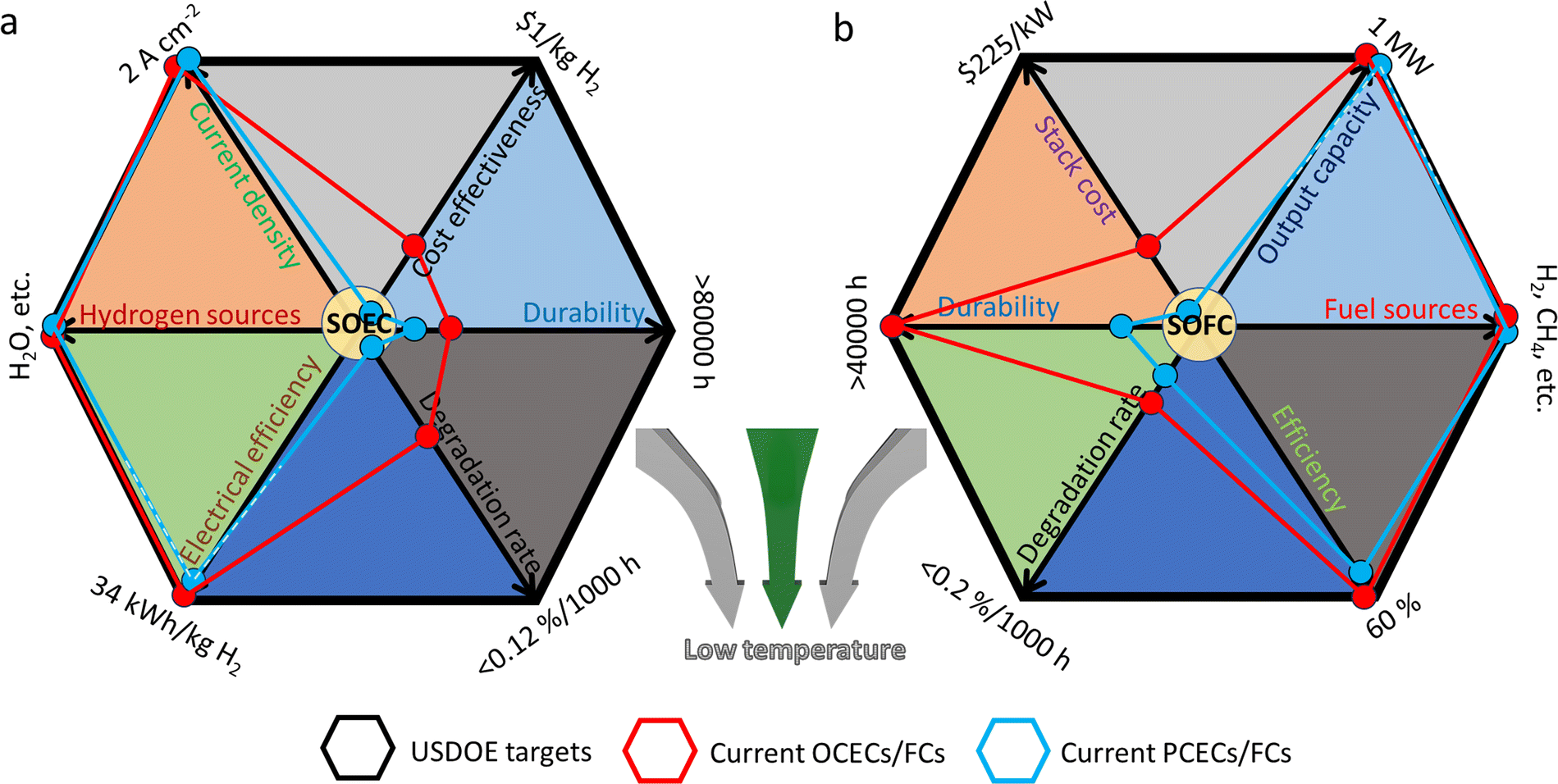 | ||
| Fig. 1 Key commercial targets proposed by USDOE,33,34 and current development status of (a) CECs for hydrogen production (SOEC) and (b) power generation (SOFC). Plotted by the authors, in accordance with the experimental data of recent typical literature. (a) Current density (OCEC,40 PCEC41), hydrogen sources (OCEC,42 PCEC43), electrical efficiency (OCEC,34 PCEC,14 expected to reach the goal), degradation rate (OCEC: 0.3–0.4%/1000 h at 800 °C,44 PCEC: <30 mV/1000 h14), durability (OCEC: 10700 h,45 20000 h,34 PCEC: 1200 h14), and cost effectiveness (OCEC: >4 $ per kg H2,34 PCEC: lack of reliable data). (b) Stack cost (OCFC,46 PCFC: lack of reliable data), durability (OCFC: 15000 h,45 ten years,47 PCFC: 8000 h48), degradation rate (OCFC: ∼0.5%/1000 h,47 PCFC: <1.5%/1000 h48), efficiency (OCFC,49 PCFC: 57.8% LHV50), fuel sources (OCFC,51 PCFC48), and output capacity (OCFC,52 PCFC,53 expected to reach the goal). | ||
Various effective attempts have been made to reduce the operating temperatures of CECs. For electrolytes, a direct method toward decreasing ohmic resistance is by strict fabrication of ultrathin electrolyte films. Nevertheless, a thin electrolyte film, like a 5 µm-thick membrane, seems to be the ultimate limit without the usage of sophisticated equipment for most research labs.54 Meanwhile, an ultrathin electrolyte would inevitably increase the fabrication cost of CECs and bring more challenges for scale-up production. For electrodes, the electrochemical reaction properties, such as the gas adsorption ability and ionic conduction capacity, are still confined under a relatively low level. Mixed ionic and electronic conducting electrodes (MIECs, mainly referred to oxygen-ion and electronic conductors) are popular candidates for OCCs,55 while triple protonic-oxygen ion-electronic conducting electrodes are theoretically and experimentally under evaluation for PCCs.56 The traditional electrodes are commonly composed of micro-scale grains. They are confined to a low level of electrochemical reaction kinetics, due to their large particle size with inert exposed surfaces and inferior catalytic sites. Fortunately, nanotechnologies provide an alternative way out for efficient construction of ceramic particles with advanced ionic conductivity and catalytic activities, which have attracted wide interest as nanoreactors and have been regarded as the next-generation candidates for electrolyte and electrode materials in CECs.57 Once the particle size is reduced from the micron to nano scale, the aforementioned challenges may be addressed. As discussed in this review, nano-sized materials demonstrate advanced properties and elevated catalytic activities when being used in CECs, and are very beneficial for the improvement of mass transfer in electrolytes and reaction kinetics in electrodes. Therefore, technical processing toward achieving nano-scale materials will be one of the most important approaches for the development of CECs.
The objective of the present work is to make a comprehensive review on the nanotechnologies in CECs. The key fundamentals of CECs, such as the working principles of different CECs, the mass transfer and electrode reactions, and some essential requirements for CECs, were first summarized and analysed. Then current challenges in CECs were presented followed by in-detail discussion of the impacts of nanotechnologies on the optimization of electrochemical reaction activities. The fourth part involved the working principles of different types of nanotechnologies that are frequently used toward fabrication of nano-size particles and architectures, while the fifth section focused on the latest progress in electrolytes and electrodes of CECs via nanoengineering. Finally, constructive perspectives to achieve promising breakthroughs toward advanced CECs via nanotechnologies were evaluated in order to reveal new opportunities in the fundamental research area and wide commercialization of CECs.
2. Fundamentals of CECs
2.1 Cell configurations
As for traditional energy generation, electrical power is obtained from a gas turbine generator by mechanical work via a cyclic gas volume variation and heat exchange driven by the direct combustion reaction between H2 and O2, as shown in Fig. 2a. Actually, the chemical energy should be first transformed into thermal energy before being converted into electrical power. The efficiency of the whole system is strictly limited by the maximum value of the “Carnot cycle”, which suffers from the loss of a majority of chemical energy by thermal losses. Auxiliary electrical equipment can be integrated for increasing the total energy conversion efficiency, but will increase the overall cost of the mechanical system. Originally different from the conventional extensive power generation mode, a CEC is a direct “chemical energy ↔ electrical power” conversion device which is capable of surpassing the “Carnot cycle” limit.58 As shown in Fig. 2, a typical CEC mainly structurally consists of three different components: a fuel electrode (also known as the anode in fuel cells), an electrolyte membrane, and an air electrode (or known as the cathode in fuel cells). As for H2/O2-involved reactions, the hydrogen oxidation reaction (HOR) or the hydrogen evolution reaction (HER) occurs at the fuel electrode, which will generate oxidized hydrogen (proton)/hydrogen gas, together with the formation of free electrons/oxygen in the other side. The electrolyte is commonly a dense membrane, working as an ionic conductor for sustainable transport of charged species from the fuel electrode to air electrode, or in the opposite direction. Electronic conduction in the electrolyte should be completely suppressed, while considerable ionic conduction, i.e. oxygen ions for OCCs (Fig. 2c and f) and protons for PCCs (Fig. 2d and g), prevails, which will greatly determine the cell performances. The air electrode is a porous layer, in which the oxygen reduction reaction (ORR, in fuel mode) or the oxygen evolution reaction (OER, in electrolysis mode) takes place. To maintain remarkable energy conversion ability, the above electrochemical processes should be activated in a relatively low temperature range. To maximize the reaction kinetics, the ionic conduction of the electrodes should be maintained at a superior level, together with a favourable electronic conductivity. In OCFCs, when fed with H2, H2O is produced at the fuel electrode, while in PCFCs, the exhaust is generated at the air electrode side. For dual-ion conducting fuel cells (DCFCs), the mixed proton and oxygen ion conduction in the electrolyte facilitates the exhaust emissions at both electrodes simultaneously. For OCECs, when being fed with H2O in the fuel electrode, hydrogen will be generated in the same side and oxygen gas will be formed in the other side. In PCECs, H2O is supplied in the air electrode side, and hydrogen is formed in the fuel electrode side. In addition, as for dual-ion conducting electrolysis cells, H2O can be supplied into both electrode sides in order to maintain sustainable redox reactions.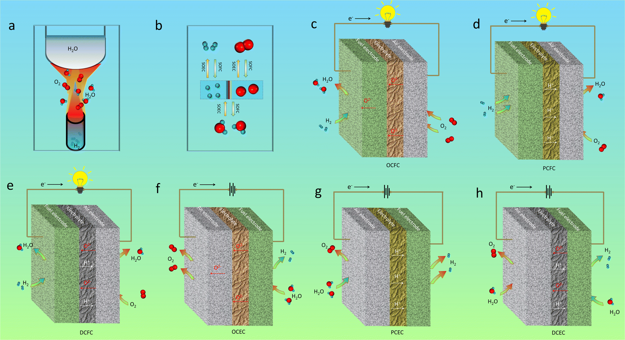 | ||
| Fig. 2 (a) A representation of traditional direct combustion reaction between H2 and O2. (b) A brief illustration of H–O-based electrochemical reactions via CECs (SOFCs and SOECs). Schematic diagrams of SOFCs: (c) a cell based on an oxygen ion-conducting electrolyte (OCFC), (d) protonic ceramic fuel cell (PCFC), and (e) dual-ion-conducting fuel cell (DCFC). Schematic diagrams of SOECs: (f) oxygen ion-conducting electrolysis cell (OCEC), (g) protonic ceramic electrolysis cell (PCEC), and (h) dual-ion-conducting electrolysis cell (DCEC). Plotted by the authors. | ||
It should be noted that, though a CEC is able to work in reversible modes (SOFCs and SOECs), without changing electrolyte and electrode materials,59 their working principles differ a lot. Firstly, the working conditions, such as the driving voltages, for the cells are much different. Higher operating voltage of SOECs makes the electrodes more prone to be activated. The microstructural evolution of the materials may also be triggered out when being employed under different voltages. Secondly, the mode differences make the adsorbed species (including contaminants) on the electrode different. Then totally different surficial catalytic reactions will occur, which may be the reason for different long-term stability behaviours of the fuel cells and electrolysis cells with the same materials.60 Thirdly, the electrochemical reactions, such as the power generation from hydrogen in fuel cell mode, are exothermal reactions, while the H2O electrolysis is an endothermic reaction. Therefore, theoretical efficiency of an electrolysis cell is generally higher than that of a fuel cell. Consequently, these may be the reasons why the same materials would display much different sustainability properties in different working modes.
2.2 Basic requirements for operating CECs
To ensure high cell performance, as mentioned above, a CEC should be composed of an electrolyte membrane with strong ionic conductivity but negligible electronic conductivity, and an electrode with superior catalytic properties, including appropriate adsorption ability to reactive species, good mass transfer abilities (O2− and /or H+), electronic conductivity, etc. The cell polarization loss is contributed by both electrolyte and electrode ohmic resistance and electrode polarization resistance. Electronic conduction is essential and helpful in reducing the ohmic resistance of electrodes. In metal-based electrodes, electronic conduction follows the free-electron theory. In semiconductor-based electrodes composed of multivalent metal ions, electronic conduction follows the Zerner double exchange mode transporting between the metal lattice and the oxygen ions,61,62 as sketched in Fig. 3a. In air electrodes, p-type electronic defects (i.e. hole,h·) are predominantly generated through the capture of oxygen atoms by oxygen vacancies, and hole conduction overwhelms in most air electrodes: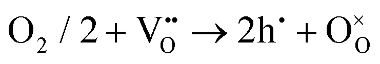 | (1) |
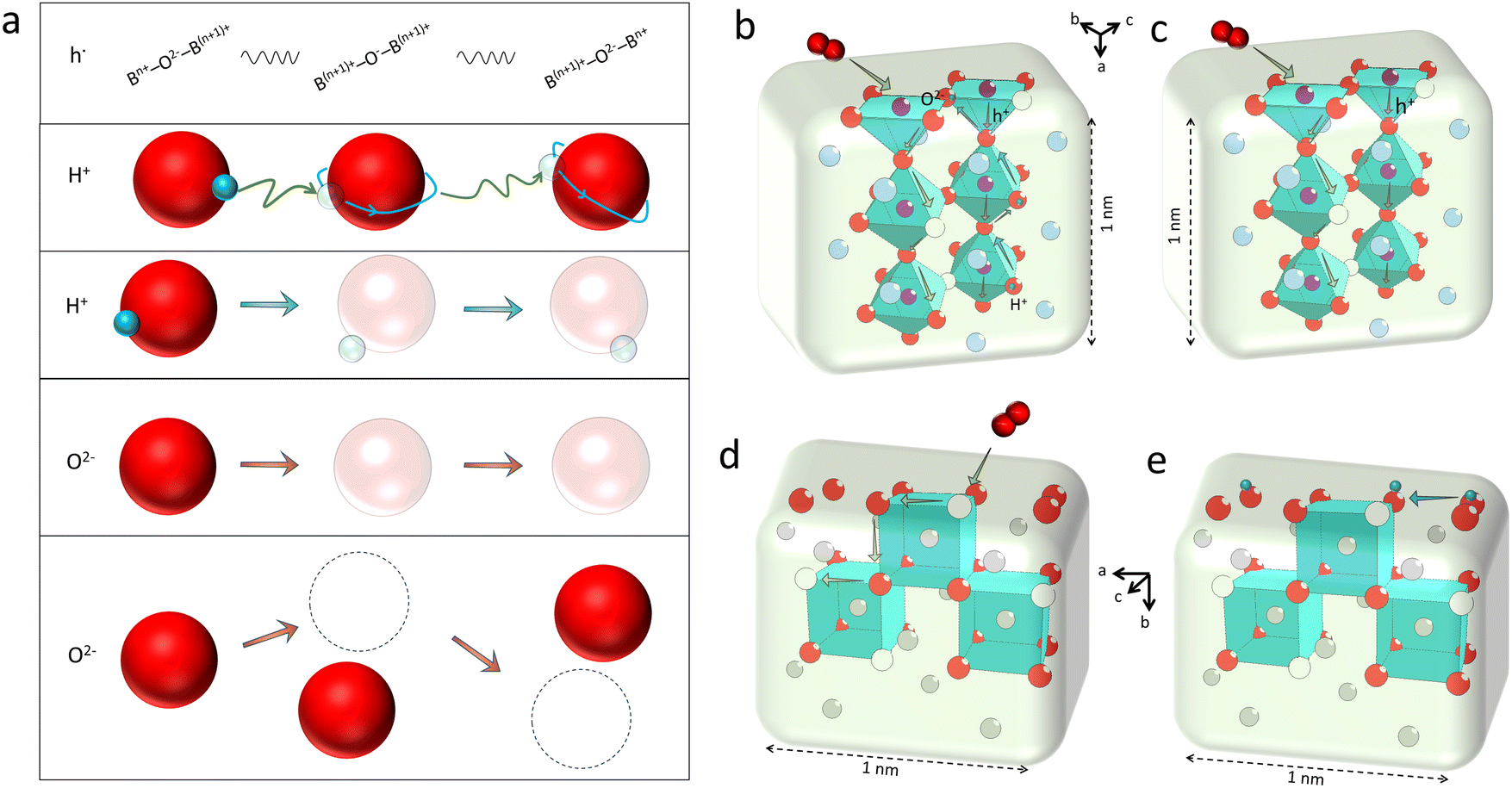 | ||
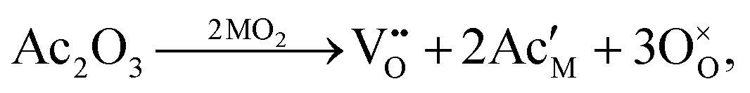
| Fig. 3 (a) From top to bottom: a brief representation of the hole transport between two different metal ions (B-site cations in perovskite); an illustration of the hopping process of the stimulated protons in two nearest-neighbour oxygen ions and the rotating process around the oxygen ions (Grotthuss mechanism); a plot of the “Vehicle mode” for the movement of a hydroxyl group (for illustration); and the “Vacancy mode”, and a simplified illustration of the “Interstitial mode” for oxygen ion transport. The transparent balls represent vacancies, while dotted circle is the interstitial space. (b) An illustration of internal transport of oxygen ions, protons and holes in a 1 nm-thick triple-conducting perovskite material. (c) Mixed oxygen ion and electronic conduction in a typical perovskite material. Both (b) and (c) plots are based on a typical BSCF structure. (d) A plot of the oxygen transport in the fluorite lattice. (e) Proton conduction across the particle surface, according to the lattice structure of doped ceria. Plotted by the authors. | ||
In CECs, oxygen ions usually transport through the following mechanisms: the “vacancy mechanism” for most oxides, and the “interstitial mechanism” in some unpacking lattices filled with plenty of suitable interspaces for oxygen ion transport, as displayed in Fig. 3a.63,64 Oxygen vacancies are generated through acceptor (denoted as Ac) substitution, as descripted using the following equation:
 | (2) |
 is the oxygen vacancy, and
  represents the lattice oxygen. The high-temperature stimulated oxygen ions could transport from a vacancy to another driven by the spatial oxygen concentration, which is named as the “vacancy mechanism”. On the other hand, the “interstitial mechanism” works without the involvement of oxygen vacancies. Despite this, this ion transport mode puts forward higher requirements for the lattice configuration of the solids.
Due to their small ionic radius, protons are usually not able to occupy a regular site in solids, and then could not transport through the lattice occupation mode individually under most conditions. Instead, protons are prone to bond with other ions, such as oxide ions, forming an OH-group. Then a hydroxyl group could transport between different oxygen vacancies, which is termed as the “vehicle mechanism”. But in another mode, long-distance proton diffusion could be realized through a direct hopping process of one proton between two different oxygen ions, which is known as the “Grotthuss mechanism”. In this mode, protons could move between two oxygen ions, and a rotation movement around oxygen ions seems to be necessary for the hopping process.
2.3 Sustainability and cost requirements
Additional requirements for practical applications of CECs include high chemical stability, strong thermal and mechanical sustainability and low cost. The first prerequisite for advanced CECs is the excellent chemical endurance of the materials against different atmospheres, such as CO2, SO2, H2O, and so on. Furthermore, high-level thermal stability is also essential and important for practical applications of CECs. Good thermal stability calls for high stability of cell components, a durable textured structure, and good thermal matching between different layers under variable temperature/atmospheres. In terms of the cell endurance, the cycling ability that represents the repeatability of the cell performance when being switched between different calcination temperatures and atmospheres is also an important factor that should be noted. Moreover, the materials used in CECs should be accessible and achievable through facile scale-up manufacturing, and affordable with low financial cost.3. Present challenges in CECs and opportunities through nanotechnologies
3.1 Challenges in CECs
The stringent requirements as mentioned above lead to large challenges against widespread practical applications of CEC technologies because most popular catalysts used in CECs are inert oxides at room temperature, which should be thermally activated at high temperature. The first challenge that should be overcome is the decrease of operating temperature, especially in comparison with other energy conversion cells. For example, the operating temperature of most of the proton exchange membrane (PEM) cells is below 250 °C (or even lower).65 Such a low working temperature makes it attainable to use this technology in practical applications, which also paves the way for their wide application as quick-start devices, such as vehicles with flexible electric generators or a portable hydrogen generation station.66,67 In comparison, the best service temperature of CECs is much higher than that of PEM cells. The main reason is attributed to the fact that the activation of electrolyte and most electrode catalysts implemented in CECs should be performed at high temperature. Three typical temperature ranges can be distinguished in CECs: high temperature above 750 °C, intermediate temperature ranging from 500 to 750 °C, and low temperature below 500 °C.68 In general, high temperature facilitates electrochemical reaction kinetics, including the ORR, HOR, HER and OER. The ionic conduction across the electrolyte is boosted as well. As temperature decreases, the polarization resistances corresponding to the electrode together with the ohmic resistance from the electrolyte will increase accordingly, which will inevitably degenerate the whole cell performance. High operating temperature also increases the total device cost in order to compete for a series of requirements for safe working, such as the expenses of compatible interconnectors and sealing elements. The financial cost may even be amplified for a large-scale stack since the essential device supports for the uniform temperature field, gas field, electric field, etc. will suffer from terrible challenges, while those can be drastically alleviated at a low temperature range. However, the material cost may be elevated again when increasing the loading amount of active catalysts to compete the suppressed catalytic activity at low temperature. The main reason is ascribed to the inert catalytic ability of the electrolytes and electrodes.Another big challenge for CECs is the inferior long-term sustainability and cyclability. The sustainability of a cell describes its total service life span, while the cyclability represents the repeatability of the cell performance during thermal cycles, or when being used in different atmospheres, or even being switched between different working modes. For practical applications, assessment should be conducted for at least ten thousand hours of working. A low performance degeneration rate and a stable chemo-mechanical configuration against a thousand times of cycling should be realized. The achievement of high sustainability and cyclability calls for strong compositional and structural stability of the materials. However, up to now, it is still a tremendously difficult target to achieve, even for most cutting-edge and state-of-the-art materials reported. Moreover, the fabrication processes and financial cost require urgent attention, such as the sintering process of electrolyte layers and membrane fabrication in scalable processes. Therefore, searching for next-generation catalysts and electrolytes with advanced catalytic performance, superior stability and low financial cost at reduced temperature is most urgent and important for the development of CECs.
3.2 Opportunities from nanotechnologies for CECs
When the size of catalysts varies from the macro (>100 µm) to micro (0.1–100 µm) to nano scale (1–100 nm), interesting and fantastic phenomena that are distinguished from bulks will emerge out. Nanoparticles (NPs) possess a large difference in the spatial composition distribution and lattice structure, compared to the micro and macro-scaled grains. These differences then bring numerous advantages. First, surficial metal ions exposed to the adsorbed groups may be rearranged, more surficial defects may be generated, and thus, the adsorption energy to the active species will be reduced. Second, as for electrodes, the total length of three phase boundaries (TPBs) will be greatly increased due to the high specific surface areas when using nano-sized particles. Top-level length of TPBs is favourable to the redox reaction kinetics. Meanwhile, the activation energy for ionic transport can be reduced as well. All of the above aspects allow achieving outstanding catalytic activities, and boosted cell performances will be expected. As follows, the most favourable effects related to nanotechnologies are discussed from the perspectives of individual particles to different cell sections, in order to clarify the original differences between nanoparticles and larger grains in CECs.Research on nano-size defects in CECs remains scarce making the accurate evaluation of their effects difficult. Even so, some research results about solids provide valuable references. For example, Maier et al. pointed out that when the size decreased at least three effects could be triggered out, i.e. the overall transport property effect, mesoscopic space charge effect, and mesoscopic structural effect.70 Drozd et al. employed a modelling method to study the oxygen vacancies in an anatase TiO2 NP with a size of 1.1 nm, and compared the results to those obtained for a NP model with a twice larger size.71 It was theoretically supported that the size decrease of anatase NPs greatly facilitated the formation of surface oxygen vacancies and Ti3+ ions. These pioneering results indicate the differences in the defect distribution of NPs in comparison with bulk catalysts, and can provide important information for an in-depth understanding of nano-size effects on the materials in CECs.
As discussed above, the oxygen ion diffusion in oxides usually follows the “vacancy mechanism” between different oxygen ion sites, while the transport of protons and electrons complies with the “hopping mechanism”. Fig. 3b and c display the mass transport in a perovskite on the basis of the BSCF lattice model with periodical 2.5 units of the perovskite octahedra in height (about 1 nm). Fig. 3d and e demonstrate the oxygen ion diffusion in the bulk or across the fluorite surface on the basis of 20 mol% Sm doped ceria with three hexahedrons in length (about 1 nm). In these nanograins, the decreased size could probably not change the transport modes of the diffused charges, but would greatly affect the ionic and electronic conductivities through increasing the active site densities, which in turn, boost the mass transfer and energy conversion abilities. On the other hand, as the catalyst size grows (above 100 nm), the bulk lattice will be filled with high stacking, and the total ionic conductivity of the catalyst will be dominated by the bulk conductivity, as comparatively displayed in Fig. 4a and b.
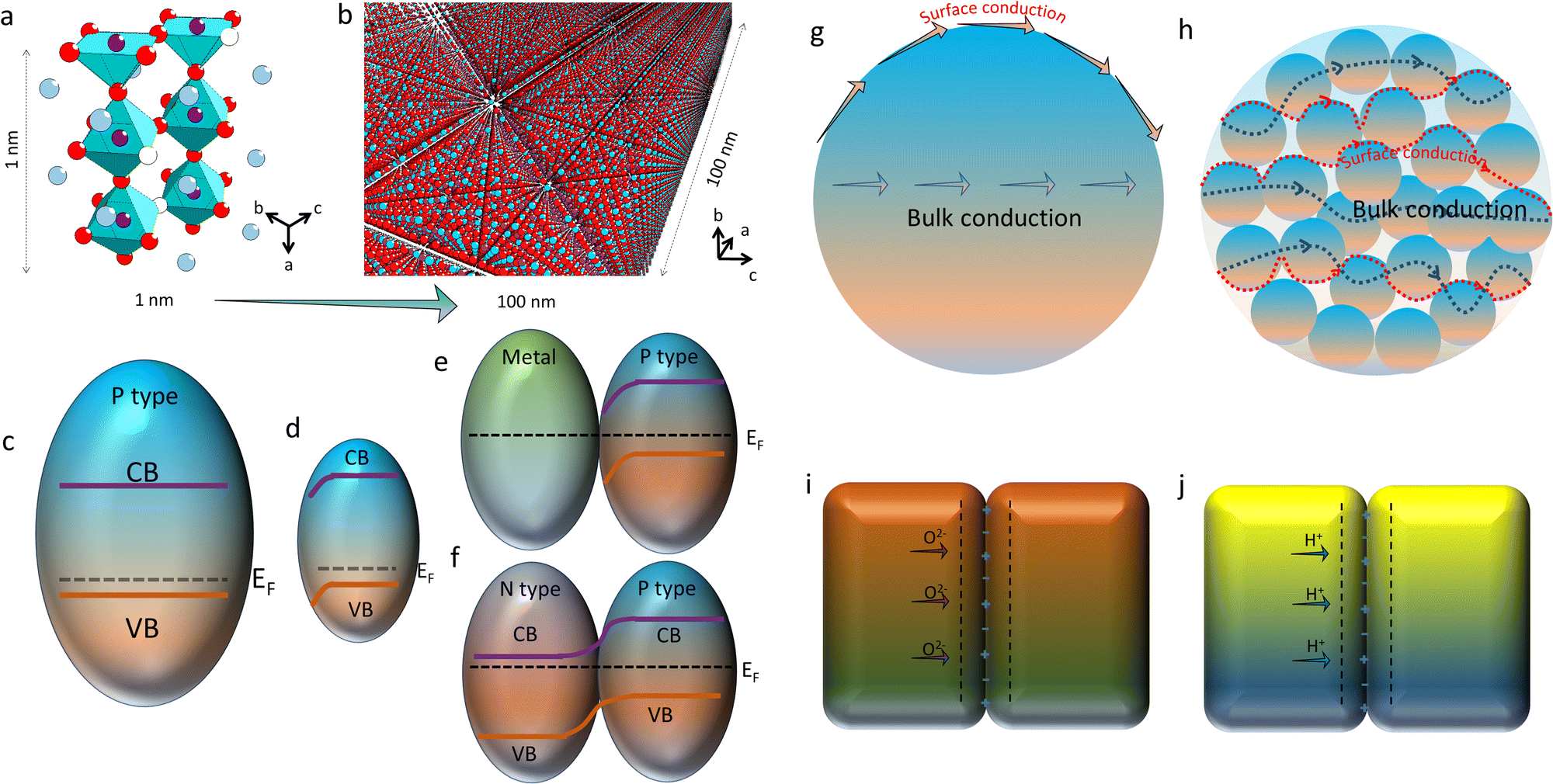 | ||
| Fig. 4 (a) Structural BSCF lattice with periodical 2.5 BO6 octahedra along the a axis, dimensionally equalling to 1 nm. (b) BSCF nanocrystalline material with a dimension of about 100 nm along the a axis. (c) A typical p-type semiconductor with a conduction band (CB), valence band (VB) and Femi band (EF) locating near VB. (d) Band bending near the surface in the nano semiconductor. (e) A metal/p-type semiconductor contact with the band bending near the semiconductor surface. (f) A P–N junction contact with the band bending near the contact. (g) Ionic conduction across the surface and inside the lattice, i.e. the boundary conduction and bulk conduction of the ionic conductor. (h) The boundary conduction and bulk conduction in the nano-sized crystalline group, with the same volume as (g) for comparison. Mott–Schottky barrier model for illustrations of: (i) oxygen ion diffusion and (j) proton conduction. Plotted by the authors. | ||
With regard to electronic conduction, the band structure of nano-sized electrode materials may be rearranged, either for p-type or n-type materials. When the grain size turns into the nano scale, high density of defects on the surface would give rise to new features for catalytic reactions. One notable nano-size effect is the formation of a space-charge zone. Obviously, the energy band variation caused by the space-charge effect on the surface will affect the electronic conductivities of the solids through bending the energy band across the surface, as illustrated in Fig. 4c and d. Moreover, the energy band bending of the space-charge zone could be strengthened while different types of grains contact with each other, as sketched in Fig. 4e and f. For instance, the strong contact between a metal particle and a p-type semiconductor pulls the Femi levels of different materials into the same level, which allows the free transport of stimulated charges between them. Another classical model is a P–N junction which is generated between a p-type semiconductor and a n-type semiconductor. The band bending on the interface of the grains would greatly affect the electron transport ability of the hybrid. When being used as the catalyst, the unipolar conductivity of the P–N junction would endow CECs with multiple new fantastic properties.
In addition to the electronic conduction, the oxygen ion conduction in nanocrystalline materials could also be much different from the bulk materials. As we know, for polycrystalline ceramics, the oxygen ion transport can be simply divided into two individual parts: the bulk and surface diffusion. The first part describes the ionic conduction through the sample interior, while the latter one is related to the mass transfer on the grain surface, such as on the electrode which is comprised of O2 adsorption, dissociation and incorporation of O2− once the material is fed with air.72 As described in great many literature studies,73–75 the activation energy of ionic diffusion along the surface is usually lower than that of the bulk, implying that the oxygen ion diffusion along the surface is more prone to be triggered out. It is reasonable to expect an elevated ionic conductivity once the oxygen ion diffusion is mainly contributed by the activated surface, apart from the grain bulk. As comparatively shown in Fig. 4g and h, once the space was filled with the same volume of ionic conductors, the nanocrystalline sample possesses a larger surface area compared to the bulk sample. With more exposed surfaces to the adsorbed species, high ionic conductivity along the active surfaces may be accomplished. Apart from oxygen ion transport, proton conduction may also be affected by active surfaces. More active sites produce more proton defects. Then, improved proton conduction could be achieved in nano-sized samples. Meanwhile, it was reported that the spacing of interfaces offers a powerful degree of freedom.76 Interesting phenomena, such as the effect of the space-charge zone (or the Mott–Schottky depletion layer), may be generated,77 and thereby the proton and oxygen ion conduction and the redox reactions on the interfaces may be affected, as sketched in Fig. 4i and j. Therefore, the electrochemical reaction rates may increase extremely with the decrease of the catalyst size.
Consequently, nanotechnologies play tremendous roles in the modification of electrodes and electrolytes. As sketched in Fig. 2, the HOR and HER are two key processes that are used for the assessment of fuel electrode activities in CECs. The H2 adsorption/desorption, dissociation/association and ionic conduction processes of the catalysts are the main electrochemical steps occurring in a fuel electrode. In addition, the chemical endurance of fuel electrode materials against reducing gas is crucial for maintaining the long-term stability of CECs. For an electrode equipped with a nanocatalyst, the adsorption of H2 and the dissociation abilities toward protons are able to be strengthened owing to the increased amount of exposed surface areas. Meanwhile, high proton conductivity can be achieved in PCFCs/PCECs as their active surfaces possess high-level oxygen vacancies working as proton transport channels. In OCFCs/OCECs, since water is produced at/fed into fuel electrodes, oxygen ion conduction works as a desirable factor that can influence their catalytic activity. Ni-based cermets, i.e. Ni metal coupled with ceramic materials, are commonly used as fuel electrodes.78 Ni serves as the HOR/HER catalytic site while the ceramic component usually acts as the ionic conducting phase. For fuel electrode-supported CECs, the fuel electrode and electrolyte should first be sintered together at high temperature in order to densify the electrolyte membrane. Normally, most NPs would inevitably evolve into large grains on the macro/micro scale at such densification temperature. Nevertheless, once NPs are introduced into the fuel electrode after the densification process, it is reasonable to believe that HOR/HER kinetics will be revitalized. It implies that the nanotechnology is an attractive and efficient pathway toward rational design of advanced fuel electrodes. Then, it is reasonable to understand that the introduction of a mixed ionic and electronic conducting phase into the electrode backbone can increase the surface reaction kinetics and decrease ion diffusion resistance, which has been evidenced by electrochemical impedance spectroscopy (EIS) analysis results.79
A typical structure derived from nanotechnology is a nano-sized hybrid electrolyte cell. Here, the hybrid electrolyte is usually composed of two or more nano-scaled components with a heterojunction structure (for example, a P–N junction) in order to suppress internal electronic short circuit. Two different kinds of semiconductors, p-type and n-type semiconductors, are commonly employed to construct a heterojunction. Under real working conditions, orientational electronic conduction is realized. Four advantages of the nano-type electrolyte are as follows. First, since the electrolyte is fabricated at low temperature, plenty of pores connecting with each other could be preserved inside the electrolyte, which drastically benefits the mass transfer of reactants. Second, the ionic conduction of the electrolyte is improved. Unlike dense membranes, the ionic conductivity of the porous electrolyte may be much different. For a conventional high-density electrolyte, the ionic transport resistance along the grain interfaces is usually regarded as a negative factor for the total ionic conduction of the electrolyte. However, when electrolyte materials are processed into small particles (100 nm or below), surficial ionic conduction would be remarkable or even prevail over the bulk conduction due to the absence of surficial defects. As a result, nano-size electrolyte membranes could exhibit higher ionic conductivity than the dense electrolyte membranes with coarse grains.80,81 Third, the most favorable operating temperature range of nano-electrolyte-based cells is always much lower than that of traditional dense electrolytes. Carbonate-based hybrid CECs are a good example.82,83 The best operating temperature for this type of cell usually locates at the melting point of the salt, at which the best mobility of the flux along the interface could be achieved. As we know, most fluxes that are implemented in nano-size electrolytes are alkali metal salts, and their melting points are usually below 600 °C. As a result, the operating temperature with superior ionic conductivity is usually set around this temperature. High ionic conductivity, efficient mass transfer, abundant active sites for charged species, etc., effectively accelerate the electrochemical reaction rates for the cell and then drive the fourth benefit-high cell performance at low temperature. Actually, as shown in many literature studies, the cells with nano-materials usually output much higher PPDs, demonstrating positive effects of nanotechnologies on electrolytes.82,84
In CECs, air electrodes work under an oxidizing atmosphere. As for the air electrodes of OCFCs/ECs, the oxygen ion and electronic conduction is believed to be in high relevance to the electrochemical reactions in air electrodes, while for air electrodes of PCFCs/ECs, triple oxygen ion-proton-electron conducting materials are required to promote the electrode reaction kinetics. In OCFCs/ECs, when using micro/macro-metric particles, the deficient surface area would limit O2 adsorption and dissociation, in addition to the O2− injection into the lattice, owing to the low oxygen vacancy concentration on the surfaces. In contrast, on NPs, almost all ORR steps could be promoted thanks to the abundant active surface sites, leading to a superior cell performance. The improvement of the oxygen incorporation rate by introduction of NPs supports this viewpoint.85 With respect to PCFCs/ECs, the enhanced proton conductivity is helpful to the charge distribution from the TPBs to the whole catalyst surfaces, which in turn drastically accelerates the electrochemical reaction rates, and then high electrode performance could be achieved. Recently, Hong and his co-workers’ EIS analyses of electrodes supported this result.86 According to their works, Rs,cat., Rp,cat. and Cp,cat. parameters expressing the activation polarization of the air electrode decreased by approximately one order, 40%, and one order of magnitude, respectively. Apart from the aforementioned parameters, nanometric particles are considered to be in close correlation with the improvement of some key geometric characteristics, such as the tortuosity factors and three-phase boundary length, which are strongly related to the key electrochemical processes.87
When investigating the impact of nanotechnologies on cell stability, the accurate definition of NP stability should be firstly provided. In comparison with bulk grains, NPs hold low sizes, more active surfaces, high density of defects, etc. and therefore are more prone to deteriorate thermal and chemical stabilities of devices. High surface energy of NPs can also induce catalyst coarsening at high temperature. Actually, the impact of nanotechnologies on cell stability is still under debate, and there have been at least two different viewpoints in the academic field till now. For instance, to improve the electrode activities, Wang et al. infiltrated Ni–Sm doped CeO2−δ into a fuel electrode and SmBa0.5Sr0.5Co2O5+δ into an air electrode.89 They ascribed the cell degradation to the high sinterability of NPs which could lead to particle coarsening. In another study, Graves et al. claimed that the degradation mechanism was reversible, and the cell degradation could be eliminated by simply operating the cell under reversible operation cycles between electrolysis and fuel-cell modes.90 On the other side, Tong and colleagues’ results evidenced enhanced stability by the infiltration of Gd doped ceria NPs.91 Besides, Phan and Haes briefly addressed their own points about the NP stability.92 They pointed out that the NP stability was highly relative to the targeted size-dependent properties, and can only be available for a finite period of time if all nanostructures are inherently thermodynamically and energetically unfavourable relative to bulk states. Accordingly, stable NPs should at least hold an unchanged aggregation state and core composition and preserve morphology (shape and size) and surface chemistry (original surface potential, chemical identity, etc.) in long-term operation mode. From this point of view, once the NPs exhibit coherent properties in the aggregation state, core composition, morphology and surface chemistry, the cell stabilities would change. Then various situations can be analysed. Herein, for electrodes that are entirely composed of NPs, the stability of heterogeneous multiple types of NPs may be much different. Phase aggregation can be suppressed. In addition, multiple components increase the system chaos and entropy, which in turn benefit the stabilities of chemical composition, morphology, and surface chemistry. A typical example is a one-pot synthesis method. The crystallization of the composite is suppressed, being very helpful for the enhancement of cell endurance. In contrast, an electrode composed of single-phase NPs will be probably reluctant to strong endurance under extremely high temperature and harsh atmosphere conditions, due to the simple component of the electrode which is prone to aggregate in extreme environments. Fortunately, most nanoelectrodes are composed of different phases or of single-phase particles with good spatial distribution, which are beneficial to their stability. In addition, it should be noted that the working mechanism involved in stability of NP catalysts is still under debate. For example, in a report, infiltration of (Sc2O3)0.1(ZrO2)0.9 scaffolds with Ni did not improve the cell stability, but brought in a decrease in active TPB density.93 The NP coarsening is considered as the main factor that is responsible for most initial electrochemical degradation of Ni-based SOFCs. In these experiments, over-calcination may be one crucial reason deteriorating the catalytic activities of NPs.
4. Technical approaches to apply nanotechnologies in CECs
4.1 High-energy mechanical ball milling
A high-energy ball milling process is a physical treatment technique in which the powder with a large particle size is subjected to high-energy collisions from the high-speed rolling balls, as sketched in Fig. 5a. Through high-energy impact and grinding from balls, large grains can be processed into NPs via appropriate milling procedures, mechanically and physically. Compared to chemical methods, high-energy ball-milling is a simple, cost-effective, green and rapid strategy for achieving NPs. Generally, the treatment will not change the sample composition but can be used to reduce the particle size into the nanoscale by appropriately controlling the milling speed and dwell time, ball to powder ratio, and milling media, in order to make sure thorough grinding of the bulk samples.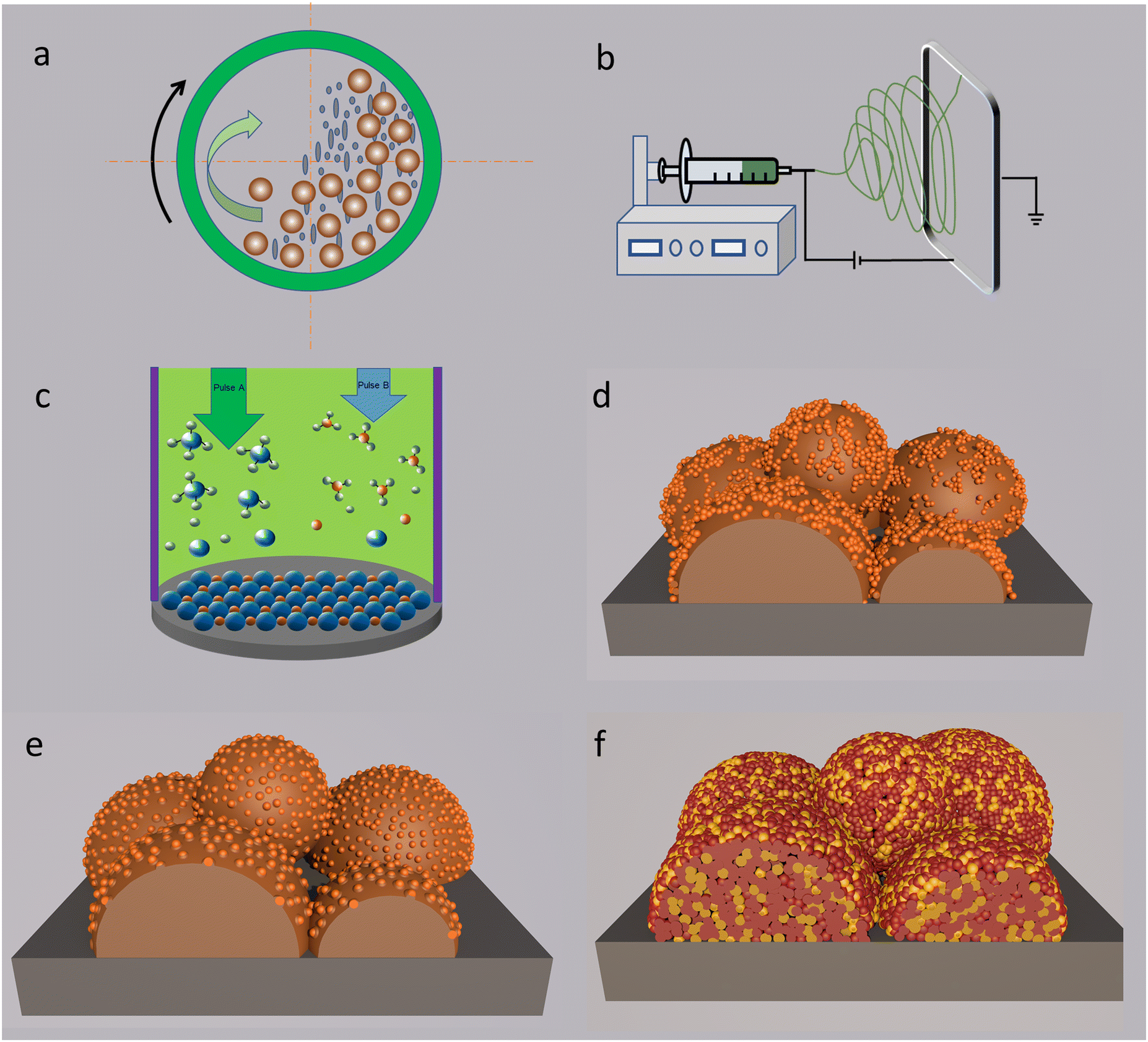 | ||
| Fig. 5 (a) A schematic sketch of high energy ball-milling treatment. (b) A representation of horizontal electrospinning apparatus. (c) A sketch of the chemical vapor deposition method. (d) Impregnation method for the modification of an electrode on the scaffold. (e) In situ exsolution strategy for construction of nanoparticles anchored on the supporting framework. (f) Self assembly of a nano-size electrode. Plotted by the authors. | ||
A high-energy ball milling method is suitable to the syntheses of electrolyte and electrode materials. For instance, nano-size particles can be directly obtained through grinding bulk electrolyte precursors. As reported by Khakpour and the co-workers, 20 mol% Gd doped ceria NPs (50 nm) with a surface area of 16.86 m2 g−1 were synthesised. The optimal rotary speed and milling time are 270 rpm and 30 h, respectively.104 The as-prepared electrolyte NPs are favourable for the membrane densification at a relatively lower temperature, due to high sinterability of NPs. With regard to electrodes, high-energy ball milling can also be applied for the synthesis of perovskite-type materials. Ghasdi and Alamdari systematically compared three classic synthesis methods, high-energy ball milling, sol–gel, and solid state reaction methods in the preparation of a LaCoO3 perovskite.105 As a result, the specimen obtained by high energy ball milling displayed the lowest crystallite size of 11 nm. The challenge is that the as-prepared NPs should be annealed at high temperature to form full ceramic cells with three distinct layers. A high-temperature cofiring process is necessary for reinforcing attachment between the air electrode and electrolyte layers. During this process, the NPs become coarsened. However, as for the porous electrode sintered at low temperature, the nano-scale morphology can still be maintained, demonstrating the wide application of a high-energy mechanical strategy.
4.2 Electrostatic spinning
As shown in Fig. 5b, the electrostatic spinning technique is supported by smart construction of an electric field between a spinneret and a substrate. Driven by strong electric field on the solution (a component carrying catalysts), nano-scale fibers will be produced on the substrate.106 The spun fibers with a nanoscale diameter provide various advantages like a high surface area along the diameter direction, abundant porosity and ionic transport ability along the length direction of the fibers.28 Since most fuel electrode-supported cells can be used as the substrates, the electrostatic spinning strategy is commonly used for generating air electrodes with fibre-structured NPs.1074.3 Chemical deposition
Chemical deposition is an in situ assembly strategy through depositing chemical compositions onto an appropriate substrate.108Fig. 5c depicts the basic working principle of a typical deposition technology-atomic layer deposition (ALD). It offers exceptional feasibility of achieving high-aspect ratio structures, thickness controllability at the Angstrom level, and membrane composition tunability.109 A post-treatment is necessary for achieving strong attachment between the adhered layer and the substrate. Chemical deposition can also be usually used for the fabrication of thin nanostructured ceramic films, such as nano-size electrolyte membranes and nanowire electrodes. Several critical parameters of the cells, such as the membrane thickness and particles morphologies can be modified by controlling the deposition processes, depending on the material varieties, depositing time, annealing temperatures, atmospheres, etc.4.4 Infiltration
Most well-developed electrode materials are cobalt or iron-based perovskites. Their phase formation temperatures are approximately around 900–1100 °C, and are prone to aggregate together into the micrometer-scale before crystallizing into pure perovskite, resulting in the deterioration of catalytic performance. Modifications are essential to revitalize the catalytic activities of the catalysts. Infiltration (or impregnation) technology is a typical surficial modification method, as displayed in Fig. 5d. The as-synthesized large grains will work as a scaffold for surficial decoration, with infiltrated phase acting as the modified composition. Scaffold materials are important for the whole performances of the cell as well.110,111 Metal-ion nitrates complexed by the sol–gel method are usually used for the synthesis of infiltration solution. The targeted metal ions in nitrates are firstly dissolved into the aqueous solution, and complexing agents are used, such as citric acid and glycine, to avoid precipitation of metal ions. Then, the diluted solution is transferred and impregnated into the scaffold, which covers the grain surfaces of the scaffold. A high temperature post-treatment is applied for the formation of a stable phase and for achieving firm adherence between the scaffold and impregnated particles, as displayed in Fig. 5d. Since the post-treatment process is usually performed at a relatively lower calcining temperature than that required for the formation of a skeleton (scaffold), nano-size co-catalysts with a uniform distribution over the framework can be prepared.The decorated layer is controllable by simply changing the impregnation solution concentration and infiltration times. Generally, component aggregation can be suppressed to some extent, and uniform distribution of the active groups will be produced. Then the decorated phase characterized by advanced catalytic activity can induce an intriguing synergistic effect between the framework body and the anchored phase. The overall reaction kinetics, especially surficial reactions, will be promoted. Various compounds can be synthesised via an infiltration process. Among them, metal and metal oxide catalysts are most frequently used to decorate the electrode skeleton. Moreover, some perovskite-type oxides can also be employed in the modification of the framework, depending on the working mechanisms of different electrode materials.
4.5 Self reconstruction
As discussed above, a high temperature treatment is essential for the formation of a targeted phase in the electrode. Interestingly, a large number of components with a fragile structure are prone to reconstruct under particular conditions, offering new opportunities for advanced modification of CEC materials. In comparison to infiltration, self reconstruction of NPs is realized from the same precursors. The electrochemical reaction kinetics may be promoted because a synergistic effect between the parent material and NPs may arise. According to the reported literature, the electrode, rather than the electrolyte, is more suitable for modification by this treatment. When being subjected to particular conditions, a catalyst component or structure will evolve depending on the composition of the precursors. To date, at least three different strategies have been developed and used for self-reconstruction. They are in situ exsolution, self-assembling technology and a thorough decomposition method.4.5.1.1 Reduction/corrosion reaction-derived exsolution. Many transition metal ions in bulk catalysts are prone to be reduced into pure metal under reducing atmospheres, for example, H2. These metal ions include Ni, Co, Fe ions, etc. NPs will be formed once the accumulation amount of the exsolved metal reaches a tipping point. Herein, the derived nano metals work as the active sites for surficial electrochemical reactions. Fuel electrodes are usually modified using this strategy due to the reducing conditions they encountered. For example, using a Ni-doped catalyst, Ni NPs can be easily formed on a grain surface when being exposed to a reducing atmosphere. Research on synthesis of Ni-based electrodes via an exsolution strategy contributes a series of reports in the literature. Very surprisingly, as confirmed by recent reports, internal lattice strain might be introduced during the exsolution process, which was proved to be helpful for further improvement of electrochemical reactions, such as the ionic conduction.112–114
Similar to H2 treatment, surficial reconstruction can also be realized via external H2O corrosion, particularly for SOECs since their air electrodes are exposed to H2O directly.115 To improve the electrode performance, the candidates used for H2O treatment must be chemically sensitive to steam. Then the derived particles should be composed of the composition beneficial to electrochemical activities. More importantly, it is suggested that the growth of the decorated components should be controllable to some extent, rather than being completely decomposed into species, even when the electrodes are exposed to the moist atmospheres with high vapour pressure, in order to avoid structure collapse in electrodes.
4.5.1.2 Electrochemical poling. By applying an electric potential on the electrode as the driving force, metal NPs can be forced out anchoring on the electrode surface in some chemical compositions. The derived NPs’ amount mainly depend on the relative values of the reduction potential of metal ions. This method has been successfully used for in situ assembling of some perovskite-type oxides.116 For example, for the purpose of poling B-site metal, A site deficiencies and reducing atmospheres are very helpful to this process. In brief, the applied voltage, the material compositions, the gas atmospheres, etc. enormously influence the composition and exsolved amount of derivatives, and also provide new opportunities for rational design of novel functional materials.
4.5.1.3 Thermally driven exsolution. This technology is achieved with the aid of thermal treatment. Since most candidates used in CECs are complex metal ion-based oxides, just like perovskites, a very high temperature sintering process is essential for the formation of catalysts with a pure phase. Very interestingly, some catalysts with disequilibrium in chemical compositions, such as A or B site deficiencies, are able to produce derived phases which also anchor on the catalyst surface while being annealed at high temperature. Therefore, the sintering temperature, dwell time, as well as the material's crystalline features, such as the crystal surface orientation, are related factors that will influence the exsolution processes of NPs.117 Moreover, composition design of the precursors is still very critical to the final products of the derived phases.
4.6 Metal ion substitution
Catalysts substituted by sintering-resistant dopants are helpful for suppressing the growth of particle sizes. These dopants include Zr, W, and rare earth ions, etc. Ionic substitution can reduce the catalyst sinterability, enable the catalysts to endure high temperature, and suppress the particle growth rate. For example, Jung et al. used a La dopant in BSCF, and synthesized nano-size perovskite particles with a composition of Lax(Ba0.5Sr0.5)1−xCo0.8Fe0.2O3−δ.119 The results demonstrated that the lanthanum concentration and annealing temperature showed high relevance to the oxide defect chemistry and particle growth. But their electrocatalytic performances were not investigated in CECs. To sum up, metal ion substitution usually demonstrates modest effect on reducing the particle sizes compared to other methods, according to recent experimental results.4.7 Template fabrication
In addition to NPs, the distribution of the active sites for electrochemical reactions are also highly related to the morphological characteristics of electrodes. For example, the pore morphology of the electrode is highly associated with the cell performance, which has attracted wide research interest.120–122 The major reason may be attributed to its correlation with active species and TPBs, which is one key factor impacting the catalyst properties.123 Different pore sizes result in distinct active sites for mass transport, and nanopores will work as nanoreactors for electrochemical reactions with increased active sites. The in-depth reason behind the pore effect has not been clearly unveiled in CECs till now, partially due to their harsh operation conditions. Fortunately, the effects of the pore morphology on cell performance have been intensively researched in PEMs, which provides useful reference for CECs. Very recently, Wang et al. reported a size-sensitive molecular probe method to study the pore effect in Fe/N/C catalysts using different-sized organics.124 Their findings showed that more than 70% of the ORR activity was contributed by the 0.8 to 2.0 nm micropores. In contrast, the active sites in mesopores and macropores were degenerated by interfacial acid–alkaline interactions, leading to inactive TPBs. This result presents that the nanopores in catalysts are the most active sites for internal electrochemical reactions for room-temperature fuel cells. The outcomes may provide strong support to and reference for high-temperature CECs. Therefore, regulating the pore structure is a useful strategy helpful for elevating the electrochemical activities, and efficient construction of nanopores is one promising way for boosting the catalytic activities. The pore size facilitates confinement for gas transport and ionic conduction, which is considered to be dominated by the electrostatic effects at the solid electrolyte interface.125A template approach is a typical technical strategy to stimulate the syntheses of electrode textures with porous structures or nanopores. Under most conditions, the template is first preconfigured to prepare a desirable morphology of the aimed materials. The synthesis process usually involves metal oxide/polymer templates containing cylindrical pores with a uniform diameter. The nano-sized cylindrical pores are then filled with material precursors via particular technical processes, for example the sol–gel method and electrodeposition. After that, the template is removed forming desired NPs with a porous texture. Till now, template fabrication has been frequently used in syntheses of different morphologies of functional materials, such as nanopores, nanoparticels,126 nanofibers,127etc.
4.8 Other methods
The sol–gel self-combustion method is an effective and economical synthesis technique for the preparation of aimed products and has been frequently used for the syntheses of a series of electrolyte and electrode materials for CECs,128,129 photocatalysts,130 phosphors,131 for electrical or magnetic engineering applications.132 It is used for the synthesis of nano-sized and homogeneously distributed materials by mixing diverse elements at the atomic level. One issue is that most nano-size electrolyte and electrode materials obtained by the sol–gel combustion method are sintered at high temperature in order to build multi-layer membranes. The sinterability of the as-prepared NPs would be important for the final products. In addition, various derived strategies are explored in combination with the sol–gel combustion method, such as microwave-assisted sol–gel combustion,133 spray pyrolysis,134etc. Take spray pyrolysis for example, it shows high relevance to the sol–gel combustion strategy, in which a precursor solution is atomized in a droplet generating apparatus, evaporated by a heating reactor, and then decomposed into particles or films. Several steps are usually involved: evaporation of the solvent out of the droplets, drying the droplets into precipitates, annealing the precipitates, formation of microporous particles with defined phases, generation of solid particles, and annealing treatment of solid phases at high temperatures.5. Current status of nanotechnologies in CECs
5.1 Nanotechnologies in fuel electrodes
Infiltration is a facile pathway for the preparation of nano-sized fuel electrode particles. Gao et al. proposed a new processing strategy for the fabrication of (La0.9Sr0.1)0.98Ga0.8Mg0.2O3−δ (LSGM0.98), a promising electrolyte in SOFCs, and the as-prepared cell can easily achieve high PPD (>1 Wcm−2) at an intermediate temperature range (<650 °C).138 In their work, they first cofired the ceramic layer-porous La0.2Sr0.8TiO3−δ (LST) support, porous LSGM and dense LSGM layers, and carried out a process of infiltrating nanometric Ni into porous layers. The novel procedure resulted a low Rp of 0.188 Ω cm2 at 650 °C for the cell decorated with an optimized anode functional layer (AFL). Besides, a high PPD value of 1.12 W cm−2 was achieved at 650 °C. The optimization was attributed to the optimization of electrode materials. This work demonstrated great application potentialities of Ni NP infiltration. In another work, Zhu et al. combined SrFeO3−δ with Ni NPs for impregnation treatment, and employed it as a fuel electrode for SOECs.139 In the viewpoint of the authors, the finely distributed Ni NPs on the substrate enlarged TPBs for efficient electrochemical CO2 splitting. Electrochemical results showed that the as-tailored SrFeO3−δ demonstrated better properties, and then performed well in a stability test of 100 hours and 8 redox cycles. Wang et al. infiltrated Ni cocatalysts into a Sr2Fe1.5Mo0.5O6−δ (SFM)–Ce0.8Sm0.2O1.9 (SDC) fuel electrode to facilitate the electrolysis process for a methane-involved reaction.140 It was found that, after Ni infiltration, the surface oxygen exchange coefficient greatly increased by about 7 fold and the current density was strongly enhanced over twice at 850 °C. The SFM scaffold was infiltrated by Ni nitrate as well, working as a reversible CEC (R-CEC), as reported by Xu and colleagues (Fig. 6a).141 Compared to a bare SFM-based SOFC, the PPD value was increased from 259 mW cm−2 to 361 mW cm−2 in a LSGM-supported cell. When exposed to a CO2–CO mixture gas, a current density of 0.745 A cm−2 was recorded at 1.6 V and 800 °C in electrolysis mode. Besides, many valuable works concentrated on the infiltration strategy, and considerable enhancements in cell performance were achieved. Herein, some representative literature studies (in the last 5 years) that are related to the infiltration method are summarized by categories of SOFCs, SOECs and R-CECs and presented in Tables 1–3.
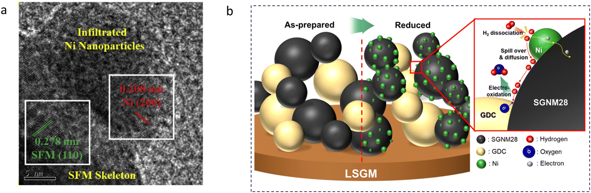 | ||
| Fig. 6 (a) Micro-morphology of a Ni infiltrated SFM catalyst. Reproduced with permission from 141. Copyright 2021, Elsevier. (b) A schematic comparison of the pristine and reduced SGNM28–GDC. Reproduced with permission from 142. Copyright 2019, American Chemical Society. | ||
| Cell configurations | NP compositions | Sizes | Nanotechnologies | Cell performances (Rp and PPDs) | Notes and ref. |
|---|---|---|---|---|---|
| NiO–BaZr0.1Ce0.7Y0.1Yb0.1O3−δ (BZCYYb1711, 65:35 wt%)|BZCYYb1711 + 1 wt% NiO|BaCe0.4Fe0.4Co0.2O3−δ (BCFC) |
Ce-Rich orthorhombic phase and Fe-rich cubic phase (air electrode) | — | One-pot synthesis | 0.075 Ω cm2 at 700 °C, 0.335 W cm−2 at 700 °C | 143 |
| NiO–YSZ|YSZ|SDC|BaCoO3−δ (BCO)–La0.6Sr0.4Co0.2Fe0.8O3−δ (LSCF) | BCO | 50–200 nm | Infiltration | ∼0.05 Ω cm2 in a symmetrical cell, 0.514 W cm−2 at 700 °C | Cr-Tolerance electrode144 |
| NiO–BaZr0.8Y0.2O3−δ (BZY) (60:40 wt%)|BZY|Sm0.5Sr0.5CoO3−δ (SSC)/PrBaCo2O5+δ (PBCO)–BZY |
SSC, PBCO | 50–80 nm | Infiltration | 0.602 W cm−2, 0.08 Ω cm2 at 600 °C (with SSC), 0.650 W cm−2, 0.07 Ω cm2, at 600 °C (with PBCO) | 145 |
| NiO–BaZr0.1Ce0.7Y0.2O3−δ (BZCY172)|BZCY172|(Pr0.9La0.1)2(Ni0.74Cu0.21Nb0.05)O4+δ (PLNCN)–BZCY172 | PLNCN | 10–20 nm when loading 27.3 wt% PLNCN, 50–200 nm when loading 46.1 wt% PLNCN | Infiltration | 0.77 W cm−2 and 0.127 Ω cm2, at 700 °C | 146 |
| NiO–BaCe0.5Zr0.35Y0.15O3−δ (BZCY53515, 60:40 wt%)|BZCY53515|BZCY53515–La0.6Sr0.4Co0.2Fe0.8O3−δ (LSCF6428) |
BZCY53515 (NPs)-embedded LSCF6428 fiber | Fiber (90–150 nm in diameter) embedded with BZCY53515 NPs | Infiltration | 0.537 W cm−2 and 0.181 Ω cm2, at 700 °C | 147 |
| NiO–BaZr0.2Ce0.6Y0.1Yb0.1O3−δ (BZCYYb2611, 60:40 wt%)|NiO–BZCYYb2611(AFL)|BZCYYb2611|Pd–PrBa0.5Sr0.5Co1.5Fe0.5O5+δ (PBSCF) |
Pd-Deposited PBSCF | 15 nm-thick layer for the sample deposited for 3 min | Infiltration | 0.42 W cm−2 at 500 °C | Low-temperature operation148 |
| NiO–BZCYYb2611 (60:40 wt%)|NiO–BZCYYb2611 (AFL)|BZCYYb2611|PBSCF |
Pd deposited fuel electrode | 3 nm (apparently) | ALD deposition | 0.34 W cm−2 at 500 °C | Ammonia fuel149 |
| Fe22Cr support|La0.4Sr0.4Fe0.03Ni0.03Ti0.94O3 (LSFNT)–FeCr–ScYSZ infiltrated by NiO–GDC20|ScYSZ|GDC20|(La0.6Sr0.4)0.99CoO3−δ (LSC) | Ni (fuel electrode) | Ni 50 nm | Infiltration | 0.650 W cm−2 at 0.7 V and 700 °C, with a fuel utilization of 31% | 150 |
| La0.6Sr0.2Cr0.85Ni0.15O3−δ (LSCrN)–Ce0.9Gd0.1O1.95 (GDC10) (80:20 wt%)|NiO–GDC10(60:40 wt%)|GDC10|La0.6Sr0.4Co0.2Fe0.8O3−δ (LSCF)–GDC10 (70:30 wt%) |
Exsolved Ni NPs (fuel electrode side) | ∼30 nm | Exsolution | 0.758 W cm−2 and 0.11 Ω cm2 at 750 °C | In 50% CO2–50% CH4151 |
| NiO–SDC|SDC|Ba0.95(Co0.4Fe0.4Zr0.1Y0.1)0.95Ni0.05O3−δ (BCFZYN) | BCFZYN anchored by NiO NPs | — | Exsolution | 1.15 W cm−2 (550 °C), 0.036 Ω cm2 | OCFC152 |
| NiO–BZCYYb1711 (60:40 wt%)|BZCYYb1711|Ba0.95(Co0.4Fe0.4Zr0.1Y0.1)0.95Ni0.05O3−δ (BCFZYN) |
BCFZYN anchored by NiO NPs | — | Exsolution | 0.54 W cm−2 (550 °C) and 0.281 Ω cm2 | PCFC152 |
| (La0.6Sr0.4)0.95Fe0.9Mo0.1O3−δ (LSFM)/(La0.6Sr0.4)0.95Fe0.7Ni0.2Mo0.1O3−δ (LSFNM)/(La0.6Sr0.4)0.95Fe0.7Co0.2Mo0.1O3−δ (LSFCM)/(La0.6Sr0.4)0.95Fe0.7Co0.1Ni0.1Mo0.1O3−δ (LSFCNM)|BZCY172|LSCF-SDC | Fe/Ni/Co nano alloys | Fe–Ni alloy: 25–30 nm, Fe–Co alloy: 10–20 nm, Fe–Co–Ni alloy: 20–25 nm | Exsolution | 0.258 W cm−2 (LSFCNM, 750 °C), 0.54 Ω cm2 (750 °C) | Symmetric cell, ethane fuel153 |
| NiO–YSZ|YSZ|GDC|Ba0.9K0.1Co0.7Fe0.2Y0.1O3−δ (BKCFY) | BaCoO3−δ (BCO) NPs exsolved from BKCFY | — | Exsolution | 0.790 W cm−2, 0.048 Ω cm2 (wet air, 700 °C) | 154 |
| NiO–BZCYYb1711(60:40 wt%)|NiO-BZCYYb1711 (AFL)|BZCYYb1711|Ag-doped BCFZY |
Ag | <50 nm (apparently) | Exsolution | 1.2 W cm−2, 0.06 Ω cm2 (650 °C) | 155 |
| (Pr0.5Sr0.5)0.9Fe0.8Ru0.1Nb0.1O3−δ (PSFRN)–Ce0.9Gd0.1O1.95 (GDC10) (50:50 wt%)|La0.8Sr0.2Ga0.83Mg0.17O3−δ|La0.6Sr0.4Co0.2Fe0.8O3−δ (LSCF) –GDC (60:40 wt%) |
Fe0.7Ru0.3–FeOx | ∼50 nm with the shell size of 2–3 nm | Exsolution | 0.683 W cm−2 and 0.034 Ω cm2 (wet H2, 750 °C), 0.374 W cm−2 and 0.198 Ω cm2 at 750 °C and wet C3H8 | 156 |
| La0.43Ca0.37Ti0.94Ni0.06O3−δ (LCTN)|YSZ|(La0.8Sr0.2)0.95MnO3−δ (LSM)–YSZ (50:50 wt%) |
Ni | 14 ± 3 nm | Exsolution | 1.003 W cm−2 at 900 °C | YSZ supported cell, thermal shock treatment157 |
| NiO–SDC (60:40 wt%)|SDC|BaCo0.8Nb0.1Ta0.1O3−δ (BCNT)|Ba0.95Ag0.05Co0.8Nb0.1Ta0.1O3−δ (BACNT) |
Ag and BCNT | BCNT: 100 nm, Ag NPs | PLD + exsolution | ∼1 W cm−2 at 600 °C, 0.02 Ω cm2 at 650 °C | 158 |
| Sr2Fe1.3Mo0.5Ni0.2O6−δ (SFMNi)–YSZ|YSZ|SFMNi–YSZ | Fe–Ni alloy | — | Exsolution | 0.116 W cm−2, 0.93 Ω cm2 at 750 °C, fed with wet H2, 0.1 W cm−2 at 750 °C, fed with wet C3H8 | Infiltrating symmetrical cell159 |
| NiO–BCZYYb1711|NiO-BCZYYb1711(AFL)|BCZYYb1711|Pr2Ni0.5Mn0.5O4+δ | PrOx | — | One-pot synthesis | 0.65 W cm−2 (700 °C), 0.052 Ω cm2 (700 °C) (symmetrical cell) | 160 |
| NiO–BZCYYb1711|BZCYYb1711|Ba(CeCo)0.4(FeZr)0.1O3−δ (BCCFZ) precursor | Rhombohedral and cubic phases | Rhombohedral (23.80 nm) and cubic particles (44.01 nm) | One-pot synthesis | 1.054 W cm−2, 0.089 Ω cm2 (650 °C) (symmetrical cell) | 161 |
| NiO–BZCY271(60:40 wt%)|BZCY271|Sr4Fe4Co2O13+δ precursor-BZCY271 (70:30 wt%) |
A tetragonal perovskite (Sr8Fe8O23+δ, 81 wt%) and a spinel phase (Co3O4, 19 wt%) | — | One-pot synthesis | 0.535 W cm−2, 0.677 Ω cm2 (550 °C) (coupled with BZCY271) | 162 |
| Anodic aluminium oxide|NiO-GDC|YSZ|Pt | Ni, GDC | — | Magnetron sputtering | 0.648 W cm−2 and 0.44 Ω cm2 at 500 °C | Nanofibrous texture163 |
| Cell configurations | NP composition | Sizes | Electrolysis current densities | Faraday efficiencies | Notes and ref. |
|---|---|---|---|---|---|
| Pt|GDC|La2NiO4−δ (LNO)–La0.8Sr0.2Co0.8Ni0.2O3−δ (LSCN) (4:96 wt%) |
LNO NPs | — | An overpotential of 0.104 V at 0.50 A cm−2 (750 °C) | — | 1.2 mm GDC electrolyte supported cell, infiltration164 |
| NiO–YSZ|YSZ|Ce0.9Co0.1O2−δ–La1−xSrxMnO3−δ (LSM)–YSZ (60:40 wt%, loaded by 7.8 wt% Ce0.9Co0.1O2−δ (CDC)) |
CDC NPs | 30 nm CDC | 1.26 A cm−2 at 1.3 V at 800 °C | 100% (assumed value) | Under 50% humidity, infiltration165 |
| Porous 430L steel support|porous 430L/SSZ|porous SSZ, with SmBa0.5Sr0.5Co2O5+δ (SBSCO) infiltrated into air electrodes and SDC/Ni into fuel electrodes | SDC/Ni, SBSCO NPs | 20–100 nm for SDC/Ni, 50 nm for SBSCO | 0.73 A cm−2 at 1.3 V in 50% H2O–50% H2, 0.95 A cm−2 at 1.5 V in 90% CO2 – 10% CO, at 650 °C | — | Infiltration166 |
| La0.8Sr0.2Cr0.5Fe0.5O3−δ (LSCrF)–YSZ|YSZ|YSZ–LSCrF, impregnated with Ni–SDC catalysts | Ni–SDC NPs | — | ∼0.4 A cm−2 at 0.3 V and 850 °C | >90% | Symmetric cell, CH4–assisted co-electrolysis of H2O and CO2,infiltration167 |
| BaCO3-modified NiO–Zr0.85Y0.15O2−δ (YSZ, 60:40 wt%)|YSZ|La0.8Sr0.2MnO3−δ (LSM)–YSZ (60:40 wt%) |
BaCO3 NPs | ∼70 nm | 0.69 A cm−2 at 1.3 V and 800 °C (0.45 A cm−2, without BaCO3 modification) | — | 168 |
| GDC20 infiltrated-Sr2Fe1.5Mo0.5O6−δ (SFM) |Gd0.2Ce0.8O1.9 (GDC20)|YSZ|(La0.75Sr0.25)0.95MnO3−δ (LSM)–YSZ (50:50 wt%) |
GDC NPs | GDC: 10–20 nm | 0.446 A cm−2 at 1.6 V and 800 °C (12.8 wt% GDC loading) | — | Electrolyte-supported SOEC, infiltration169 |
| SDC-modified 430 stainless steel|YSZ|La0.6Sr0.4Co0.2Fe0.8O3−δ (LSCF) –SDC | SDC NPs | SDC: 20–30 nm | 1.38 A cm−2 at 1.5 V, at 800 °C | — | CO2 electrolysis, infiltration170 |
| Ce0.9Mn0.1O2−δ (CMO)-infiltrated (La0.75Sr0.25)0.95(Cr0.5Mn0.5)O3−δ–Ce0.8Gd0.2O1.9 (LSCM–GDC20, 60:40 wt%)|YSZ|(La0.8Sr0.2)MnO3−δ–ScSZ ((Sc2O3)0.10(CeO2)0.01(ZrO2)0.89 (LSM–ScSZ, 60:40 wt%)) |
CMO | 10–15 nm | 0.52 A cm−2 at 1.8 V and 800 °C | — | Electrolyte supported cell, infiltration171 |
| Pd–GDC20 infiltrated LSCM–YSZ|YSZ|LSCF–YSZ (50:50 wt%) |
Pd–GDC10 | 50–70 nm | 0.364 A cm−2 at 1.5 V and 850 °C in CO2–CO (50:50 vol%). A consumption rate of 2362 µmol cm−2 min−1 at 0.5 V |
> 90% | Infiltration172 |
| GDC-infiltrated NiO–YSZ|GDC-infiltrated NiO–YSZ (AFL)|YSZ|GDC|La0.6Sr0.4CoO3−δ (LSC) and Gd,Pr-co-doped CeO2 (GPDC)–GDC | GDC-infiltrated fuel electrode, LSC and GPDC–infiltrated oxygen electrode | GDC: 60 nm at fuel electrode | 1.2 A cm−2 at 1.3 V and 750 °C | 100% (assumed value) | 4 × 4 cm2 cell, infiltration173 |
| Ru-CeO2-infiltrated SFM–SDC (50:50 wt%)|SDC|YSZ|LSM–SDC (50:50 wt%) |
Ru and CeO2 | 10–20 nm | 1.82 A cm−2 under 1.5 V and 800 °C in pure CO2 | — | CO2 electrolysis, infiltration174 |
| NiO–BCZYYb (60:40 wt%)|BCZYYb1711|NbTi0.4Mn0.1(Ni0.5Cu0.5)0.5O4−δ–BCZYYb1711 (65:35 wt%) |
Ni–Cu NPs | ∼35 nm | ∼30 mA cm−2 under 0.8 V in CO2, at 600 °C | 99.8% (current efficiency) | Exsolution175 |
| Sr2Fe1.4Ru0.1Mo0.5O6−δ (SFRuM)–GDC (60:40 wt%)|La0.4Ce0.6O2−δ (LDC)|LSGM|Ba0.5Sr0.5Co0.8Fe0.2O3−δ (BSCF)–GDC (50:50 wt%) |
Ru–Fe NPs | <3 nm after manipulation | 2.25 A cm−2 at 1.6 V, at 800 °C | >97% (apparently) | Exsolution176 |
| Sr2Fe1.5Mo0.5O6−δ–Ce0.8Sm0.2O1.9 (SFM–SDC, 50:50 wt%)|La0.8Sr0.2Ga0.8Mg0.2O3−δ (LSGM)|Ru (1.5 wt%)–coated SFM–SDC (50:50 wt%) |
Ru NPs | ∼96 nm | 1.06 A cm−2 and 0.38 Ω cm2, at 0.6 V and 850 °C | — | Infiltration177 |
| Cell configurations | Nano compositions | Sizes | Nanotechnologies | Cell performances SOFCs/SOECs | Notes and ref. |
|---|---|---|---|---|---|
| La0.3Sr0.6Ni0.1Ti0.9O3−δ (LSNT) fiber–GDC10 (70:30 wt%)|(Sc2O3)0.1(CeO2)0.01(ZrO2)0.89 (SSZ)|La0.2Sr0.8MnO3−δ (LSMO) fiber–GDC (70:30 wt%) |
Ni and GDC NPs, mesoporous LSNT (fuel electrode) | 30 nm Ni + mesoporous fiber | Electrospinning + in situ exsolution | 1.16 W cm−2, 0.27 Ω cm2/1.18 A cm−2 at 1.3 V (800 °C) | 178 |
| NiO–Y0.08Zr0.92O2−δ (YSZ)|GDC10|YSZ|GDC|Pr0.9Ag0.1Ba0.5Sr0.5Co2O5+δ (Ag–PBSC) nanofibers | PBSC nanofibers, Ag NPs (air electrode) | ∼20 nm (Ag) | Electrospinning + in situ exsolution | 0.06 Ω cm2, 0.5 W cm−2/0.65 A cm−2, at 700 °C | 179 |
| NiO–YSZ|YSZ|La0.8Sr0.2Co0.8Ni0.2O3−δ–Ce0.9Gd0.1O3−δ (LSCN–GDC10, 30:70 wt%) |
LSCN NPs | 50 nm (LSCN) | Infiltration | 0.1 Ω cm2, 1.336 W cm−2/2.34 A cm−2, at 1.6 V and 800 °C | 180 |
| NiO–BaZr0.1Ce0.7Y0.1Yb0.1O3−δ (BZCYYb1711) (60:40 wt%)|AFL|BZCYYb1711|BaCoO3−δ (BCO, 6 wt%) deposited La0.6Sr0.4Co0.2Fe0.8O3−δ (LSCF) |
BCO NPs | ∼50 nm | Infiltration | 1.16 W cm−2 and 0.16 Ω cm2 at 600 °C/1.8 A cm−2, at 1.3 V and 600 °C | ∼10 µm-thick electrolyte181 |
| (LaSr)0.9Fe0.9Cu0.1O4−δ (LSFCu)–Ba(Zr0.1Ce0.7Y0.2)O3−δ (BZCY172) (70:30 wt%)|BZCY|LSFCu–BZCY172 (70:30 wt%) |
Cu NPs | ∼50 nm (Cu) | Exsolution | 0.573 W cm−2, 0.19 in air and 0.36 Ω cm2 in 5 vol% H2 at 800 °C/1.02 A cm−2, at 1.2 V and 800 °C | Symmetrical cell with 211 µm electolyte182 |
| NiO–YSZ|YSZ|GDC|Pr2Ni0.8Cu0.2O4+δ (PNCO)–coated La0.6Sr0.4Co0.2Fe0.8O3−δ (LSCF) | PNCO nano film (air electrode) | < 10 nm–thick film (apparently) | Infiltration | 1.358 W cm−2 and at 750 °C/1.953 A cm−2 at 1.5 V, 0.107 Ω cm2, with 50% H2O at 750 °C | 183 |
| NiO–YSZ|Ni–YSZ (AFL)|YSZ|Ni(Mn1/3Cr2/3)2O4 (NMC) infiltrated–Gd0.1Ce0.9O2−δ (GDC10) | Ni, NMC and GDC10 | — | Ni: exsolution, NMC and GDC10: Infiltration | 1.293 W cm−2 at 800 °C in a fuel electrode-supported cell/2.32 A cm−2 at 2 V in a symmetrical cell at 850 °C | Fast recovery in composition184 |
| CeO2-infiltrated NiO–YSZ (66:34 wt%)|NiO–Fe2O3 (90:10 wt%)|Ce0.6Mn0.3Fe0.1O2−δ (CMF)-TiO2-added Ce0.6La0.4O2−δ (Ti-LDC, 0.5:99.5 wt%)|LSGM|SSC |
CeO2-infiltrated fuel electrode | — | Infiltration | 0.95 W cm−2 at 600 °C/1.07 A cm−2 at 1.6 V fed with 20% H2O–30% H2–50% Ar, at 600 °C | 185 |
| NiO–YSZ (60:40 wt%)|YSZ|SSC/SDC20-infiltrated LSM |
SDC and SSC | SDC: 10 nm, SSC: 40–50 nm | Infiltration | 1.205 W cm−2 and 0.08 Ω cm2, at 800 °C/1.62 A cm−2 at 1.5 V with 50% H2O–50% H2 + Ar, at 800 °C, for three-times infiltrated cell | 186 |
| NiO–YSZ|YSZ|infiltrated LSM–YSZ (50:50 wt% for the functional layer and 80:20 wt% for current collection layer) |
CeOx, PrOx, MnOx | 20–100 nm | Infiltration | 0.91 W cm−2 at 800 °C and 0.018 Ω cm2, at 850 °C (PrOx modification), 1 A cm−2 at 800 °C and 1.3 V (MnOx infiltration) | 187 |
| NiO–BZCYYb1711(60:40 wt%)|BZCYYb1711|Ba0.95(Co0.4Fe0.4Zr0.1Y0.1)0.95Ni0.05O3−δ (BCFZYN) |
NiO NPs | — | Sol–gel combustion, exsolution | 0.936 W cm−2/1.267 A cm−2 at 1.3 V at 600 °C | 188 |
| NiO–YSZ(50:50 wt%)|NiO–YSZ(AFL)|YSZ|GDC10|GDC10 decorated PrBa0.8Ca0.2Co2O5+δ (PBCC) |
GDC | 70 nm | Sol–gel decoration assembly | 1.74 W cm−2 at 750 °C/1.77 A cm−2 at 1.3 V and 750 °C | 189 |
| NiO–YSZ|Ni–YSZ(AFL)|YSZ|PdO and ZrO2-infiltrated (La0.8Sr0.2)0.95MnO3−δ–YSZ (LSM–YSZ) (50:50 wt%) |
PdO and ZrO2 | 35 nm | Infiltration | 1.114 W cm−2/2.322 A cm−2 under 2.0 V (750 °C) | 190 |
One issue remains that the bonding strength of infiltrated NPs with a substrate/scaffold is commonly not strong enough under most conditions, which will suppress the ion exchange between the NPs and the substrate/scaffold. In this regard, Hui et al. used a particular experimental procedure. They used Ni(NO3)2 solution in ethanol for infiltration on an A-site deficient LaxSr1−3x/2TiO3−δ (LST) perovskite.191 Optimization of the sintering process for Ni infiltration was carried out to achieve appropriate distribution. Moreover, TG analyses indicated that Ni NPs might dissolve into the lattice due to A-site deficiency of perovskite oxide, resulting in strong bonding interfaces between the NPs and the substrate.
Since the fuel electrode works under a reducing atmosphere, it is reasonable to exsolve Ni metal ions from Ni-containing materials through a reduction reaction. It is known as the in situ exsolution method. By altering the Ni content amount in the parent precursor, exsolved Ni metal NPs with different types of morphologies and various sizes will accumulate over the parent surfaces, anchoring on the grains. Kim evaluated the exsolution process of layered perovskite SrGdNixMn1−xO4±δ (x = 0.2, 0.5, and 0.8) oxides.142 The H2 temperature-programmed reduction (H2-TPR) measurement revealed that considerable exsolution of Ni NPs was observed above 650 °C in SrGdNi0.2Mn0.8O4±δ (SGNM28) when fed with H2. After being tested in 10 redox cycles at 750 °C, the electrode ASR of the SGNM28 electrode increased 0.027 Ω cm2 per cycle in H2, corresponding to a degradation rate of about 1.78%. An LSGM-supported SOFC coupled with the tailored electrode exhibited a PPD of 1.26 W cm−2 at 850 °C. Metallic Ni NPs with a diameter of about 25 nm were found to be homogeneously distributed on the SGNM28 surface. The authors recognized that the exsolved NPs significantly enhanced the HOR activity of SGNM28 through accelerating the electro-oxidation reaction at TPBs to surface-absorbed protons, as illustrated in Fig. 6b. Myung et al. illustrated the generation and growth of metal NPs on an oxide electrode with a chemical composition of La0.43Ca0.37Ti0.94Ni0.06O3−δ, by electrochemical poling of a cell at 2 V.192 Very excitingly, it only took a few seconds. The Ni-decorated electrode exhibited excellent performances both in fuel and electrolysis modes. The as-prepared fuel cell delivered a power output of 2 W cm−2 in humidified H2, and a current density of 2.75 A cm−2 at 1.3 V in 50% H2O/N2, at 900 °C. Sun from Prof. Luo's research group reported that the exsolution reaction could also be achieved in a Ni-doped La0.7Sr0.3CrO3 (LSCN) fuel electrode.193 As shown in Fig. 7a, they calculated the free energy variations of the oxides composed of different metal ions. It was found that Ni, rather than La, Sr and Cr, could be more reducible in a perovskite lattice considering its relatively negative Gibbs free energy (−46.47 kJ mol−1), while the other metal ions held positive values at the same temperature. The non-stoichiometry with partial A-site deficiency in the perovskite greatly increased the mobile oxygen vacancy density, and strongly enhanced the exsolution ability of B-site Ni ions, improving both the electronic conductivity and electrode catalytic activity. When being tested in a sour fuel, a PPD of 460 mW cm−2 in 5 thousand ppm H2S–H2 was obtained, while the PPD of a cell with stoichiometric LSCN only reached 135 mW cm−2. Duan et al. implemented a solid-state reaction method by thoroughly mixing NiO and the other raw metal oxides/carbonate together, and finally obtained a BaZr0.1Ce0.7Y0.1Yb0.1O3−δ (BCZYYb1711) and NiO composite fuel electrode.14 According to their results, exsolved Ni NPs with a size of less than 100 nm were successfully obtained. The exsolved Ni NPs were found to be beneficial to the HER process in a PCEC and the HOR process in a PCFC, as evidenced in their experimental results.
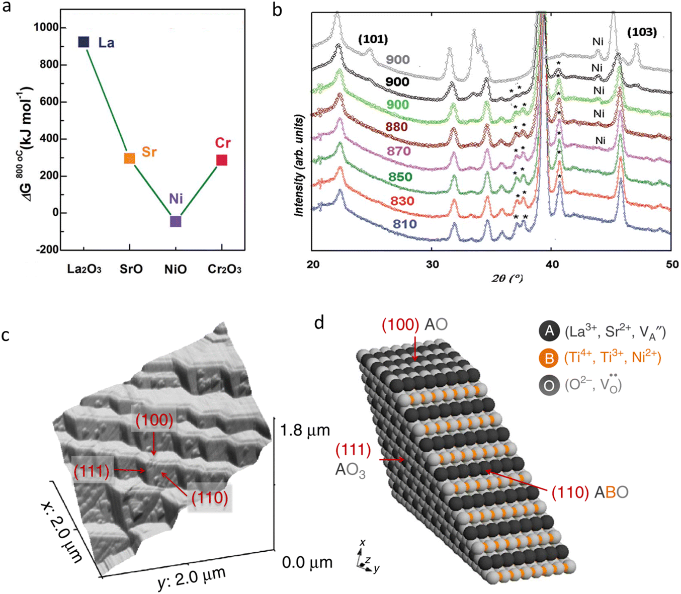 | ||
| Fig. 7 (a) Calculated values of reduction of Gibbs free energies of La, Sr, Ni, Cr oxides for the perovskite-type LSCN-15 (15 mol% Ni) sample at 800 °C. Reproduced with permission from ref. 193. Copyright 2015, the Royal Society of Chemistry. (b) In situ neutron powder diffraction results at different sintering temperatures in the Ni-doped Pr0.5Ba0.5MnO3−δ perovskite. The decrease of the perovskite (*) and increase of Ni peaks revealed the Ni exsolution reaction during the sintering process. Reproduced with permission from ref. 194. Copyright 2020, the Royal Society of Chemistry. (c) An AFM image of the native surface in the La0.4Sr0.4Ni0.03Ti0.97O3−δ specimen after being reduced. (d) An atomic scale model for the presentation of the surficial structure of terraces in (d). Reproduced with permission from ref. 195. Copyright 2015, Springer Nature. | ||
Then many literature studies evidenced that the exsolution technology is an inspirational composition engineering approach. Bahout et al. presented a complex phase evolution of Ni-incorporated Pr0.5Ba0.5MnO3−δ, i.e. (PrBa)0.975Mn1.95Ni0.05O6−δ.194 Microstructural characterization demonstrated that the specimen annealed in air at high temperature was actually composed of two different perovskites: orthorhombic Pr0.65Ba0.35Mn0.975Ni0.025O3−δ and 2H-hexagonal BaMnO3−δ with a weight ratio of 3:1. While being annealed at humid hydrogen, MnO escaped out at about 500 °C, and the orthorhombic oxide transformed into a tetragonal phase, then into a cubic phase at ∼665 °C. At 900 °C, Ni metal particles were detected to be evolved out (Fig. 7b), leaving two perovskite phases being transformed into a layered double perovskite-type oxide, PrBaMn2O5+δ, without any Ni element. The EIS results as obtained in a reducing atmosphere at 850 °C demonstrated a polarization resistance value of 0.135 Ω cm2 for the Ni-exsolved electrode. Managutti et al. synthesized several Ni-doped oxides with a chemical composition of (Pr0.5Ba0.5)1−x/2Mn1−x/2Nix/2O3−δ (x = 0, 0.05, 0.1, and 0.2, denoted as PBMNx) for catalysis application assessment.196 Phase detection and micromorphology analyses displayed that Ni metal could be exsolved around 875 °C when being subjected to a H2 atmosphere. The formation of an A-site deficiency in Ni-containing samples was found to be accountable for the exsolution process. When being equipped in a symmetrical cell, the lowest ASR was recorded as about 0.64 Ω cm2 at 850 °C for PBMN0.2 in wet 5% H2/N2, owing to the high level of the Ni content in PBMNx series. The authors then investigated the dry reforming of methane using Ni-exsolved PBMN0.2, achieving the CH4 and CO2 conversion rates of 11 and 32%, respectively, and a H2 production of 37% at 850 °C. Concurrently, a low level of carbon deposition of 0.017 g gcat−1 h−1 was yielded.
It is frequently recognized that the exsolved particles maintain strong attachment to parent substrates as compared to the coated catalysts via an infiltration strategy. Neagu et al. reported a directional research work on Ni doped La0.4Sr0.4TiO3−δ.195 They found that, unlike infiltration, the exsolved analogues (Ni) were deeply socketed into the parent material (Fig. 7c and d), implying a stronger metal–oxide interface, which contributed a lot to cell stability and a remarkable decrease of hydrocarbon coking. This work revealed the surface effects and defect interactions on the exsolution process and was valuable for facile realization of perovskites with exsolved NPs for multiple functionalities. More importantly, Kousi et al. proposed a concept that La0.8Ce0.1Ni0.4Ti0.6O3−δ endured controllable growth of metallic NPs both in a perovskite oxide lattice and on the surface while appropriately tailoring the preparation procedures (Fig. 8a).112Fig. 8b and c display the methane-involved conversion mechanism indicating the main stages associated with the redox transformations. It was displayed that, apart from the surficial NPs, the completely embedded NPs in the bulk could exchange oxygen ions with the methane outside, enabling redox conversion to syngas with excellent selectivity and cyclability when surficial NPs were present. La0.65Sr0.3Cr0.85Ni0.15O3−δ (LSCrN) was synthesized, which was characterized by surficial exsolved Ni NPs, as reported by Amaya–Dueñas et al. The authors employed it as a fuel electrode on a 5 × 5 cm2 electrolyte-supported cell.197 Ni NPs were clearly observed on LSCrN. Reversible operation (SOFC/SOEC) at 860 °C with a 50% H2O/50% H2 gas mixture was tested and the co-electrolysis operation was also conducted for over 950 h. A voltage degradation of lower than 3.5 mV per 1000 h was observed. In-depth results indicated that the exsolved NPs were stable in morphology when the electrode was performed isothermally. In these reports, the working temperature of the cell was normally lower than the temperature at which the exsolution process took place in order to maintain catalytic stability. Moreover, a co-catalytic layer at a fuel electrode can be modified by nanotechnologies. Bae et al. used a NiAl2O4 spinel catalyst as the precursor for the synthesis of Ni NPs, which were successfully used for dry reforming of methane at a fuel electrode.198 It was observed that Ni NPs on the order of 10 nm anchored on the Al2O3 support after the reduction process. The results showed that the spinel-derived Ni displayed a single rate-limiting factor of diffusion limitation at all temperature ranges avoiding suppression of surface kinetics, and demonstrated higher stability than a conventional Ni/Al2O3 catalyst, which was attributed to the enhanced interactions between the active Ni NPs and the support material. With appropriate design of parent compositions, more oxides, such as La0.95Fe0.80Ni0.05Ti0.15O3−δ,199 Sr0.8Ti0.85Ni0.1Si0.05O3−δ, Sr0.8Ti0.85Ni0.1P0.05O3−δ,200etc. were successfully used for Ni exsolution.
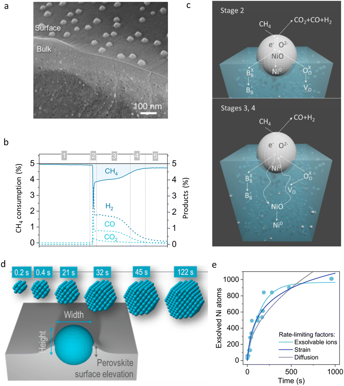 | ||
| Fig. 8 (a) Cross-section SEM view after exsolution indicating the generation of surface and bulk NPs. (b) Curves of CH4 consumption and H2, CO2, CO products. (c) A probable illustration of methane conversion pathways. Reproduced with permission from ref. 112. Copyright 2020, John Wiley and Sons. (d) Atomic scale mechanistic insight into particle exsolution. (e) Plot of the number of Ni atoms involved in a particle as a function of reduction time. Reproduced with permission from ref. 201. Copyright 2019, American Chemical Society. | ||
High-temperature treatment is also an effective way to realize the exsolution process. Tan et al. revealed a novel thermally driven exsolution phenomenon.202 In their experiments, Ni, Gd co-doped ceria was implemented. At high temperature, Ni dopants thermally exsolved, forming NPs with good attachment to the host surface, which indicated a new pathway in assembling exsolved Ni nanocatalysts. A cell with thermally exsolved Ni nanocatalysts from the 5 mol% Ni-doped specimen displayed a comparable Rp value to that of the traditional mechanically mixed Ni-GDC (Gd doped ceria), together with an improvement in TPB density, which were proved to be appropriate candidates as electrodes for SOFCs at low temperature.
Understanding the exsolution mechanism of NPs through visible investigation methods is meaningful for efficiently controlling NP growth, tailoring catalyst activity and enhancing cell stability. Neagu et al. used a high-resolution transmission electron microscope (TEM) to investigate the exsolution mechanism of individual NPs on a perovskite surface.201 As schematically displayed in Fig. 8d and e, it was revealed that the socketed, strain-inducing interface endowed exsolved NPs with high stability and reactivity. These results also provided critical information for building intriguing heterostructures and controlling the morphology of the exsolved NPs, which could be achieved by changing the gas atmosphere.
Some fantastic but efficient technologies were also reported toward modification of the size and morphology of Ni-based fuel electrodes. For example, Błaszczak et al. developed a one-pot synthesis route in the preparation of porous YSZ and Ni–YSZ particles.203 The author claimed that a wormhole-like framework with the generation of Ni NPs was realized. The decrease of the particle sizes in the electrode, high homogeneity, a well developed TPB, and an improved interfacial interaction between Ni and YSZ were regarded as the favourable factors that were very helpful for improving the fuel electrode properties.
 | ||
| Fig. 9 (a) Thermogravimetric analysis results of PBMCo in the presence of H2–N2 (10–90) composite gas. (b) In situ TEM observations of PBMCo fed with 0.5 Pa of H2 with the temperature changing from 770 (left) to 850 °C (right) with an interval of 40 °C. Reproduced with permission from ref. 205. Copyright 2016, American Chemical Society. (c) Current–voltage curves of a SOEC with Co-decorated LSCM for CO2 electrolysis. Reproduced with permission from ref. 206. Copyright 2019, Elsevier. (d) Schematic of the key reaction processes occurred on a Co-modified SFCoM surface. Replotted by the authors for illustration. (e) Comparison of RE1 (high-frequency resistance corresponding to charge transfer process) and RE2 (low frequency resistance associated with the oxygen surface process) for e-SANC and SNC0.95 specimens, tested between 550 and 650 °C. Reproduced with permission from ref. 208. Copyright 2016, American Chemical Society. (f) DFT calculation results for elucidating the co-segregation energies of Pr (grey), Ba (green), Mn (dark blue), dopants (Mn, Co, Ni and Fe, purple) and O (red) atoms. (g) A comparison of the co-segregation energies of the doped materials. Reproduced with permission from ref. 209. Copyright 2017, Springer Nature. | ||
Fe-based NPs are a promising candidate for the construction of surficial active sites for diverse electrochemical reactions. Tsekouras and the co-worker from Prof. Irvine's group made a step-change in the exsolution of perovskite-type titanates with B-site substitution and A-site cation deficiency.210 The chemical formula of the compound designed in their research was La0.4Sr0.4MxTi1−xO3−δ (M was Fe or Ni, and x was 0.06). It was then employed as a SOEC fuel electrode for steam electrolysis at 900 °C. The ingenious design of A-site deficiency offered sufficient driving force for accurate exsolution of B-site cations, forming metallic NPs. Fe NPs were found in a La0.4Sr0.4Ti0.94Fe0.06O3−δ sample, implying the achievement of a successful exsolution reaction from the parent perovskite. The authors partially ascribed the exsolution reaction to the instability of the host lattice related to the change of vacancies. The presence of active Fe NPs and inherent oxygen vacancy concentrations notably reduced the activation barrier to steam splitting in comparison with the unmodified one. In another report, Sun et al. made an experimental comparison between La0.7−xSr0.3Cr1−yFeyO3−δ (x = 0, y = 0 and x = 0, y = 0.15) and A-site deficient La0.6Sr0.3Cr0.85Fe0.15O3−δ.211 The outcomes also demonstrated that the presence of A-site deficiency facilitated the in situ exsolution process of transition metal ions. The exsolved Fe NPs on the A-site deficiency specimen provided extra active sites for the fuel oxidation reaction, which was regarded as the primary reason for the electrochemical activity enhancement.
A Sr0.95Ag0.05Co0.9Nb0.1O3−δ (SANC) perovskite oxide was prepared by Zhu and colleagues.208 Through a reduction process, nano-scale Ag particles with a size of 5–10 nm were found anchoring on the surface of the host material (labelled as e-SANC). As provided in Fig. 9e, an e-SANC electrode was demonstrated to be more active for the ORR, yielding a relatively low ASR (approximately 0.214 Ω cm2 at 500 °C). An OCFC with a decorated fuel electrode achieved an extremely high PPD of 1.116 W cm−2 at 500 °C and good sustainability for more than 100 h at a current density of 0.625 A cm−2. The enhanced activity and stability were attributed to the elevated oxygen surface exchange kinetics and successful construction of an Ag NP-anchored Sr0.95Nb0.1Co0.9O3−δ composite. Additionally, the chemical tolerance against CO2 was found to be improved too. Kosaka et al. synthesized BaCe0.8Y0.1Ru0.1O3−δ, and then annealed the perovskite in a reducing atmosphere.212 1–10 nm Ru NPs were obtained. In this report, the reduction temperature showed high correlation with the size of the exsolved particles, leading to enhanced ammonia formation capability. Herein, more representative references are collected, as presented in Tables 1–3.
A unified exsolution mechanism remains the open question till now. Several reports provided interesting and valuable references to unveiling this smart chemical process. Kwon et al. provided their own conclusion for different trends in the exsolution of some typical transition metals, including Mn, Co, Ni and Fe, while the exsolution reaction was evaluated in layered PrBaMn2O5+δ oxide on the basis of calculations, as displayed in Fig. 9f and g.209 The calculation results together with the TEM observations presented that Mn, Co and Ni could be easily exsolved from the lattice which was highly related to the transition metal–perovskite reducibility. Importantly, it was theoretically revealed that the co-segregation of B-site dopants and oxygen vacancies acted as a crucial factor in the exsolution process, as analysed by the DFT calculations.
 | ||
| Fig. 10 (a) SEM image of STFN after the cell test. (b) TEM observation of an exsolved Fe–Ni NP on STFN. (c) Polarization resistances of STF and STFN-based cells in comparison with the cell equipped with a traditional Ni-YSZ electrode. Reproduced with permission from ref. 214. Copyright 2018, Elsevier. HR-TEM observations of the surficial regions of STFN0 (d) and STFN5 (e) with the generation of a surficial exsolution reaction. Reproduced with permission from ref. 215. Copyright 2019, Elsevier. | ||
Nanoalloys can also be implemented as active sites for a fuel reformer, for instance, carbon removal. Bkour et al. established a Ni–Mo decorated YSZ functional layer for reforming isooctane with a less degree of the catalytic coking effect (Fig. 11a).217 In this research, an aqueous solution containing Ni and Mo precursors was used and mixed with the YSZ powder. Finally, a Ni–Mo nanoalloy was prepared through a reactive sintering process by drying the mixture overnight at 100 °C, annealing at 500 °C and then reducing at 750 °C in a stream of 50% H2/He. Yao et al. reported a Ni–La0.8Sr0.2FeO3−δ (LSF) composite that could be used for generation of a Ni–Fe nanoalloy.218 In this work, the authors combined impregnation and exsolution processes together. The average sizes of the as-prepared Ni–Fe NPs were controlled at 20–50 nm. A cell with 10 mol.% Ni impregnated Ni-LSF as a fuel electrode achieved a PPD of 550 mW cm−2 at 700 °C when being ehavi with syngas. The authors claimed that the strong interaction between the Ni–Fe nanoalloy and substrate should be responsible for efficient suppression of carbon deposition. Zhao et al. developed an active Cu–Fe nano-sized alloy on an Al2O3 support through a wet-impregnation method, and used it as a high temperature reforming catalyst for the reverse water gas shift reaction (Fig. 11b).219 The conversion of CO2 was greatly increased by fourfold with the modified catalyst.
 | ||
| Fig. 11 (a) A schematic illustration of the internal reforming layer fed with isooctane and air. Replotted by the authors. (b) Schematic diagram of a SOEC for CO2 reduction. Plotted by the authors. (c) Schematic sketch illustrating exsolved NPs for the CO2 reduction reaction. Plotted by the authors. (d) HRTEM pattern of the Co–Fe alloy NPs and LSCFM substrate. In situ STEM images of LSCFM: (e) after the reduction treatment in H2 at 700 °C, and (f) after the re-oxidation process in O2 at the same temperature. Reproduced with permission from ref. 220. Copyright 2020, John Wiley and Sons. (g) A typical TEM image of PSCFN powders after being reduced. (h) TEM image of the substrate/NP interface. Reproduced with permission from ref. 221. Copyright 2015, Elsevier. (i) Endurance test of 400 h at 800 °C in dry ethanol under 0.8 V after a reduction treatment in H2 for 100 h. Reproduced with permission from ref. 222. Copyright 2018, Elsevier. | ||
Lv et al. gave rise to an atomic-scale insight into the exsolution of Ni-free Co–Fe alloy NPs in La0.4Sr0.6Fe0.7Co0.2Mo0.1O3−δ (LSCFM) for CO2 electrolysis, as schematically illustrated in Fig. 11c, by employing in situ scanning TEM (STEM, Fig. 11d) and DFT simulations.220 It was pointed out that the Mo dopants occupying B sites in LSCFM worked as a driving force for the increase of the segregation energies of Co and Fe ions and enhanced the material chemical stability. In situ STEM observations clearly visualized the concurrent exsolution of Co and Fe ions, forming Co–Fe alloy NPs. More interestingly, reversible exsolution and dissolution of Co–Fe NPs were observed, as presented in Fig. 11e and f. The catalytic measurements demonstrated that the construction of a metal–oxide interface displayed high CO2 adsorption and activation, and should be highly responsible for the enhanced CO2 electrolysis performance. Yang et al. prepared a Ni-free fuel electrode composed of (Pr0.4Sr0.6)3(Fe0.85Nb0.15)2O7 (PSFN) by calcining the Pr0.4Sr0.6Co0.2Fe0.7Nb0.1O3−δ composition in H2 at 900 °C.221 Surprisingly, Co–Fe bi-metallic NPs were obtained, homogenously dispersed on the PSFN surface, as presented in Fig. 11g and h. A La0.8Sr0.2Ga0.83Mg0.17O3−δ-supported SOFC with Co–Fe anchored PCFN catalysts generated PPDs of 0.59–0.92 W cm2 in humid C3H8 at 800–850 °C, together with a stable power generation ability, suggesting a good coking resistance. In order to achieve direct utilization of dry ethanol in SOFCs, Ni–alloy@FeOx core–shell NPs were fabricated by spray-coating the additional phase onto the Ni–YSZ fuel electrode.222 No carbon deposition was observed according to their long-term sustainability research results, as shown in Fig. 11i. All the aforementioned literature studies indicated that appropriate design of pristine compositions is important for targeted NPs in order to achieve advanced electrochemical activities.
It is well recognised that the exsolution technology really promotes the development of electrode materials. As reported by Zhang et al., Ni–Fe alloy NPs decorated on Sr2Fe1.5Mo0.5O6−δ were developed. The catalysts were further modified by fluorine.223 Exsolved Ni–Fe NPs greatly changed the morphology of the catalyst surface as well as the valence states that were much helpful for boosting the adsorption behaviours of the electrode. The cell test outcomes supported that both F-substitution and Ni–Fe NPs modification enhanced CO2 adsorption density by a factor of 2.4 and increased the surface reaction rate constant (kchem) for CO2 reduction to a high rank (18.1 × 10⁻⁵ cm s−1), together with an improved oxygen chemical bulk diffusion coefficient (Dchem), which was more than doubled at 800 °C. Meanwhile, Rp decreased by a degree of 52%. At 800 °C, a remarkably high current density of 2.66 A cm−2 and a sustainability over 140 h were obtained for CO2 electrolysis in a SOEC under an applied voltage of 1.5 V. Yu and colleagues ehaviored a Fe modified Ni–Fe alloy-based SDC–Ni1−xFexOy composite.224 After evaluation in a SOEC, the most suitable Fe ratio was ascertained to be 40%. A SDC–Ni0.6Fe0.4 based cell displayed optimal stability and a low polarization impedance. The introduction of Fe was proved to be effective in preventing Ni particles from being coarsened, and hence positive for enhancing the performance of Ni-based fuel electrodes. Liu and co-workers yielded high-performance La0.6Sr0.4Fe0.8Ni0.2O3−δ (LSFN) via an exsolution strategy.225 They also successfully fabricated Fe–Ni bimetallic nanospheres. According to their TEM detection results, the exsolved alloys were found to be regularly anchored on the host oxide. A YSZ-supported reversible electrochemical cell was fabricated and tested, presenting that the electrochemical reaction kinetics for CO2 electrolysis was greatly promoted with a Rp of 0.272 Ω cm2, along with a remarkable current density as high as 1.78 A cm−2, and a faradaic efficiency value of about 98.8% at 1.6 V and 850 °C. Accordingly, the authors described that the increasing activated reactant and the improved ionic conductivity, together with the elevated electronic conductivity should be accountable for potentiating the CO2 electrolysis reaction. However, a small amount of SrCO3 was observed in their work, indicating surface segregation of Sr, which was not further analysed. Then Ding et al. from the same research group proposed a new compound with a composition of (La0.65Sr0.3Ce0.05)0.9 (Cr0.5Fe0.5)0.85Ni0.15O3−δ, and used it for in situ exsolution of Ni–Fe NPs.226 The optimized composition induced uniformly distributed perovskite-type particles socketed with Ni–Fe NPs. A cell equipped with the tailored composite displayed significantly enhanced electrochemical reaction kinetics, CO production rate, and faradaic efficiency. In addition, using distributions of relaxed time (DRT) calculations, it was depicted that the Ni additive reduced the Fe segregation energy, revealing the co-segregation of Ni and Fe ions.
Since the selectivity of the CO2 electrolysis reaction reported in the most literature is very low at low temperature,227 Liu et al. reported a novel strategy for achieving an extremely high selectivity of ∼100% toward CO using a Ni–Fe nanoalloy.228 In this work, Ni-doped Sr2Fe1.4Mo0.5Ni0.175O6−δ (SFM–Ni0.175) was utilized to derive Ni–Fe alloyed NPs with a size of ∼10 nm. Fig. 12a–d show the differences in catalytic mechanisms of SFM-Ni0.175 and a traditional Ni-cermet electrode. In situ diffuse reflectance infrared spectroscopy (DRIFTS) detection showed the suppression of the formation of formate species, which was deemed to be critical for achieving high catalytic selectivity.
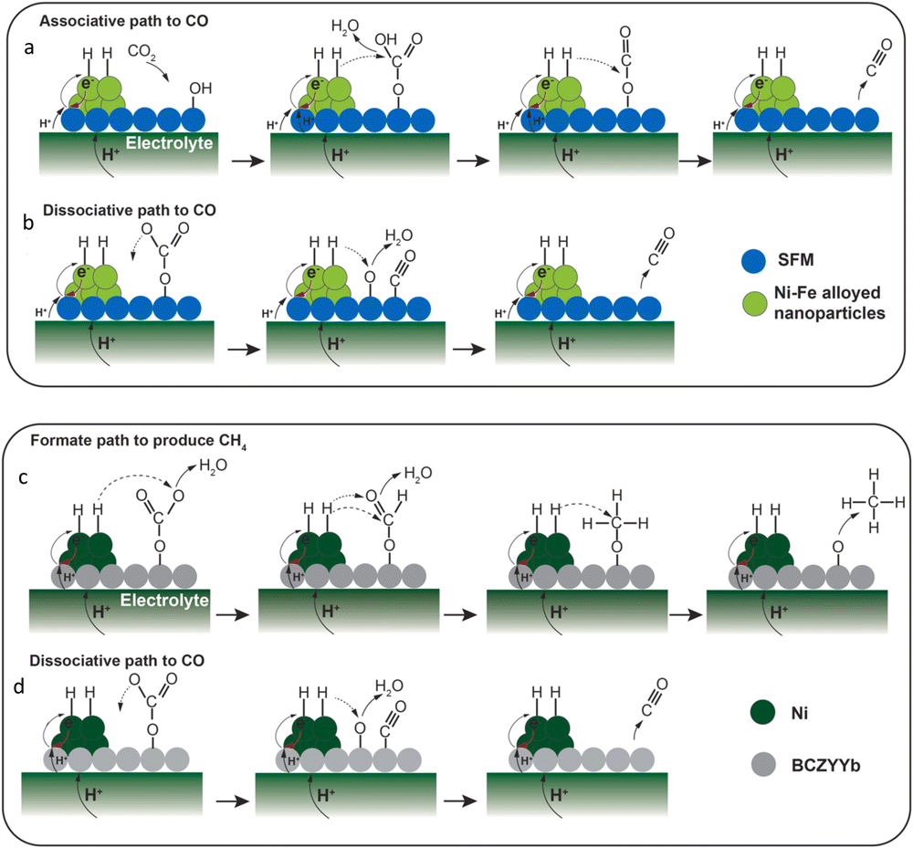 | ||
| Fig. 12 Comparative diagrams of the promising CO2 reduction pathways over SFM-Ni0.175 (a) and (b) and Ni-cermet-based electrodes (c) and (d). Reproduced with permission from ref. 228. Copyright 2022, Elsevier. | ||
Chen et al. synthesized La0.5Sr0.5Co0.45Fe0.45Nb0.1O3−δ (LSCFN).229 It was interesting that, once being annealed in 3% H2O–97% H2 between 750 and 850 °C, an A2B2O5 brownmillerite structural phase and exsolved Co–Fe alloy NPs were both detected. They drew a conclusion that the best reducing temperature for exsolution reaction was about 800 °C. It was also demonstrated that a prolonged annealing period could make the particle size even larger and increase the amounts of the Fe content and brownmillerite phase, which would result in high ohmic and resistance values. In another work, Chen et al. investigated the phase evolution ehavior of Sr0.95Ti0.35Fe0.6Ni0.05O3−δ (STFN) in 3% H2O–97% H2 at 750 °C.230 The in situ exsolved Ni0.4Fe0.6 NPs and a new composition with a chemical formula of AB0.924O3−δ were observed. The multi-phase fuel electrode demonstrated decreased polarization resistances. Kang et al. used Ni as the substituent of Cu sites in CuFe2O4 (CFO). In a reducing atmosphere, the exsolution of nano-size alloy particles was achieved.231 The power generation results demonstrated that a cell equipped with 10 mol% Ni doped CuFe2O4 exhibited the highest output (670 mW cm−2) on a LSGM electrolyte at 800 °C. The author attributed the enhanced cell performance to the nano-sized Cu–Fe–Ni alloy on the Fe–Cu metal matrix through the exsolution reaction. Based on the same viewpoint, other typical compounds modified by in-detail composition design were used for the surficial exsolution reaction. More representative literature studies are listed in Tables 1–3.
An electrochemical poling strategy was available and effective for the generation of surficial NPs. Chanthanumataporn et al. investigated the exsolution behaviour of NPs from perovskite-type La0.43Ca0.37Ni0.06Ti0.94O3−δ (LCTNi) and La0.43Ca0.37Ni0.03Fe0.03Ti0.94O3−δ (LCTNi–Fe) oxides under applied potentials in a CO2 atmosphere.232 A strong Ni NP signal was detected showing the exsolution reaction on the LCTNi substrate, while a Ni–Fe alloy was formed on the surface of LCTNi–Fe. Fig. 13a and b provide the EIS curves of the cells tested before and after electrochemical poling treatment. It was indicated that the onset of the exsolution reaction was 2 V. The average particle size of the derived NPs observed in the SEM results was around 30–100 nm, remaining in a large distribution range. The cells with the modified electrodes displayed desirable results with current densities of 0.37 A cm2 for LCTNi and 0.48 Acm2 for LCTNi–Fe, at 1.5 V in pure CO2. In SOFC mode fed with dry H2, PPDs of 0.36 W cm−2 and 0.43 W cm−2 for LCTNi and LCTNi–Fe were obtained, respectively. These results demonstrate that electrical reduction is a useful strategy in for facilitating the exsolution reaction of metallic NPs that are helpful for the improvement of CEC performances.
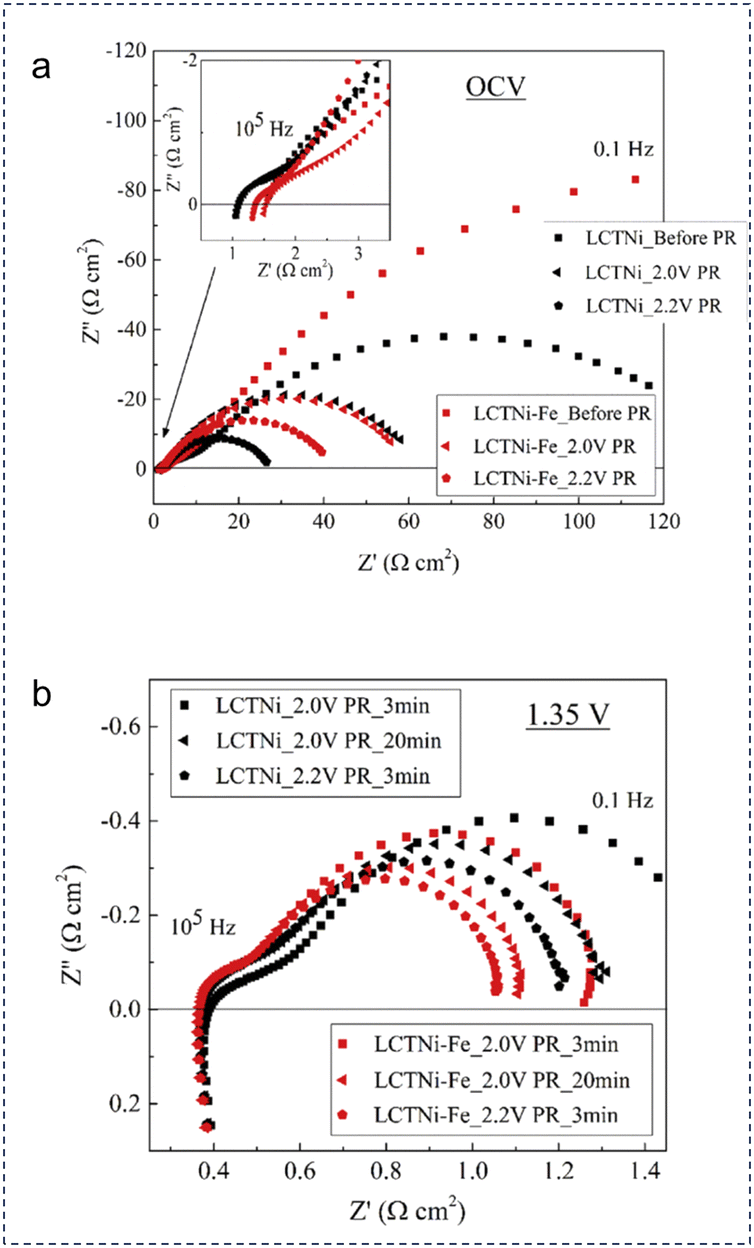 | ||
| Fig. 13 Impedance spectra of the cells equipped with LCTNi and LCTNi-Fe electrodes in CO2 as tested at 900 °C: (a) EIS curves of the samples before and after 3 min potential reduction treatment. (b) EIS results at 1.35 V after different potential reduction procedures. Reproduced with permission from ref. 232. Copyright 2019, Elsevier. | ||
In situ observation of the exsolution process in nanoalloy-anchored catalysts is very meaningful for understanding in-depth the intrinsic lattice reconstruction mechanism, but is still scarce till now. Lv et al. contributed more STEM images illustrating the in situ exsolution and dissolution processes of Co–Fe alloy NPs in Co-doped Sr2Fe1.5Mo0.5O6−δ (SFMC).233 The Co–Fe NP-anchored SFMC was demonstrated to be effective for achieving improved CO2 electrolysis activity and good sustainability.
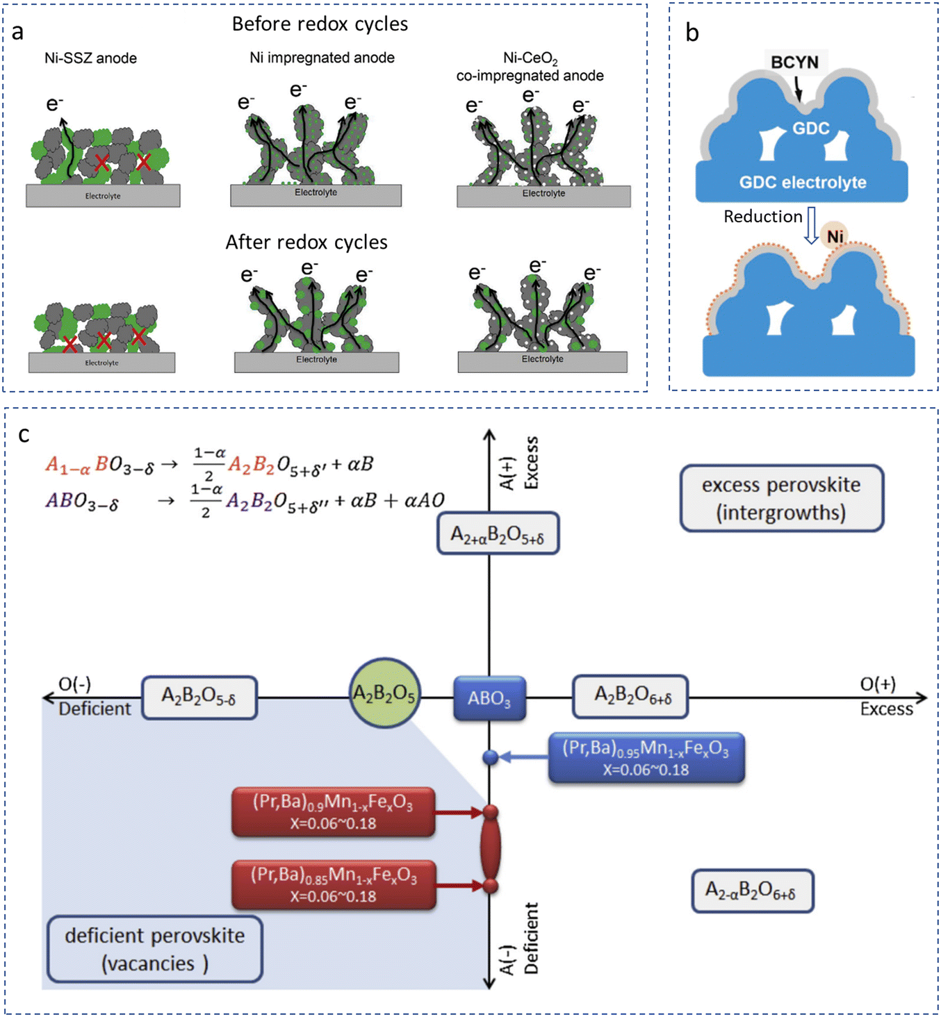 | ||
| Fig. 14 (a) The overall morphology evolution of the fuel electrode during the redox cycling test with/without infiltration on Ni-SCZ (grey: oxide, green: Ni, white: CeO2). Reproduced with permission from ref. 239. Copyright 2016, Elsevier. (b) A schematic of the reduction-induced exsolution reaction in the fuel electrode. Reproduced with permission from ref. 243. Copyright 2020, Elsevier. (c) A diagram illustrating the role of non-stoichiometry in in situ exsolution of NPs in LPBMFO. Reproduced with permission from ref. 244. Copyright 2020, Elsevier. | ||
Actually, metal ion diffusion and phase migration usually occur in the synthesis process of a fuel electrode, which may also be useful for cell optimization.245 Sciazko et al. made an effort to evaluate the morphological evolution behaviour in the Ni–GDC cermet.246 Derived from this report, a clear microstructure reorganization phenomenon was observed for both Ni and GDC particles. Significant migration of GDC NPs was confirmed based on the SEM observation. Moreover, a nano-sized GDC layer was formed on the Ni surface. The migration of the GDC phase was regarded to be of high relevance for the variation of fuel electrode performance. In addition, this work implies that the phase migration on the scale of nano size was indeed deserved to be investigated for the evaluation of SOFC stability.
Reducing the calcination temperature is helpful for scalable production of NPs. Hwang et al. fabricated Ni and Ba(Zr0.85Y0.15)O3−δ (BZY) composite NPs via impregnating a precursor composed of Ni and BZY into the BZY scaffold at the fuel electrode followed by a calcination process at 900 °C.247 The author considered that the low temperature sintering process for the fuel electrode generated the formation of a BZY and Ni nanocomposite with a size of 20–30 nm. A power output of 790 mW cm−2 at 700 °C was achieved on a 45 µm electrolyte-supported cell. Additionally, the author optimized the fuel electrode composition by infiltrating CeO2 and Pd catalysts, and finally observed that non-ohmic ASR of the Ni-cermet was improved. In another literature contributed by Li et al., Sr2Fe1.5Mo0.5O6−δ (SFM) was uniformly deposited onto a porous Y0.16Zr0.84O2−δ scaffold using aqueous metal–ion solutions through infiltration process (in a symmetrical cell).248 The conductivities were investigated at 600–750 °C, apparently displaying an increased tendency as the infiltrated amount of the SFM loading increased. As a result, the ASR values reduced to be 0.153 Ω cm2 with an optimized loading of 9.53 wt% in a 1:1 CO–CO2 mixed gas, and 0.064 Ω cm2 at 11.67 wt% in air. In SOFC mode, the MPDs of SFM-loaded cells increased with the loading amount. In electrolysis mode, the cell indicated a current density of 0.618 A cm−2 under 1.5 V for a 11.67 wt% SFM-loaded cell.
A combination of different nanotechnologies or construction of multi-phase composites can be used for achieving high-performance catalysts. Liu et al. proposed a perovskite composition for solution infiltration into the ceria backbone.243 In their work, Ba(Ce0.9Y0.1)0.8Ni0.2O3−δ (BCYN) was infiltrated onto the Gd0.1Ce0.9O2−δ (GDC) surface. Ni NPs were then exsolved as a decorated catalyst for the fuel gas cracking. As schematically shown in Fig. 14b, a Ni exsolved Ni–BCYN/GDC composite was prepared, showing attractive electrochemical activity and desirable long-term sustainability in the CH4 fuel. The Rp values of the cell with a Ni–BCYN/GDC fuel electrode were determined to be 0.085 and 0.12 Ω cm2 in H2 and CH4 at 750 °C, respectively. Song et al. prepared a composite fuel electrode composed of three phases, including Ni NPs, water-storable BaZr0.4Ce0.4Y0.2O3−δ oxide, and amorphous BaO.249 The multi-phase electrode was obtained by reducing the pristine Ba(Zr0.4Ce0.4Y0.2)0.8Ni0.2O3−δ perovskite in H2 at 800 °C.
The formation mechanism of the composite NPs still requires to be further investigated. Zhu et al. reported a facile strategy for developing Fe/MnOx NPs from a (Pr,Ba)2Mn2−yFeyO5+δ substrate, and provided a promising mechanism for the enhanced CO2 catalytic activation achieved based on the first-principles calculation method.244 Their results indicated the introduction of A-site deficiencies drove the exsolution of Fe. More interestingly, a transition from a thermodynamically nonspontaneous process to a spontaneous one was observed for the exsolution reaction. The anchored Fe particles were found to be effective for the improvement of the catalytic activities toward CO2 (638 mA cm−2 at 1.60 V). The authors attributed the activity promotion to the improvement of chemical adsorption to CO2 and the enhancement of electron conduction from exsolved NPs. As logically drawn in Fig. 14c, the oxygen and A-site non-stoichiometry were given as x and y-axes in a Cartesian plot. Fe exsolution in layered (Pr,Ba)2Mn2−yFeyO5+δ (LPBMFO) was highly suppressed since the transformation was driven by the ideal perovskite structure ABO3 to A2B2O5 stoichiometry. More oxygens should be removed in order to form double-layer LPBMFO once the reduction reaction occurred. As a consequence, for the stoichiometric LPBMFO, MnOx particles were more easily to be exsolved on the surface after the reduction process, rather than Fe. The situation might be much different for the A-site non-stoichiometry with the A/B ratio below 0.9. Once being treated under a reducing atmosphere, the deficiency of A-site cations (Pr and Ba ions) would work as a driving force to generate B-site exsolution and produce a great number of Fe/MnO composite NPs.
Technical optimization promotes the synthesis of active NPs in CECs. Somacescu et al. synthesized Ni–Ce–Y–Zr-containing oxides by a hydrothermal route, employing hexadecyltrimethylammonium bromide and tripropylamine as templates.250 Ni segregation and the increase of reduced ceria (Ce3+) were observed. These features induced more vacancies for better oxygen migration, consequently facilitating carbon removal. Yue et al. carried out the vacuum infiltration of Gd0.1Ce0.9O1.95 (GDC) nitrate solution into a (La0.75Sr0.25)0.97Cr0.5Mn0.5O3±δ (LSCM)/YSZ skeleton, and concurrently introduced a Pd catalyst into the composite.251 The nano-structured phase was found to be advantageous to boosting the electrochemical and catalytic properties toward CO2 reduction thanks to the vacuum infiltration method.
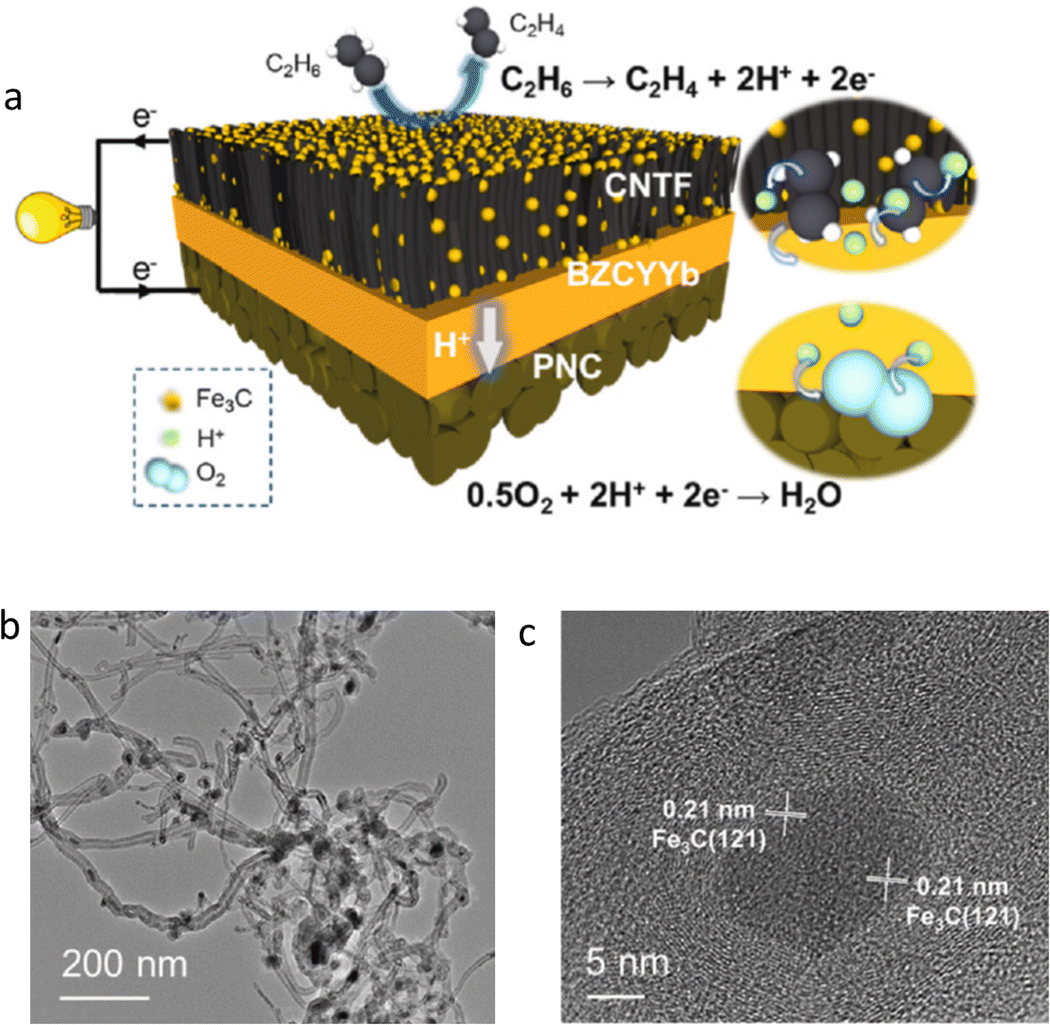 | ||
| Fig. 15 (a) Schematic of the working principle of an electrochemical cell fuelled with ethane, with a CNTF electrode. (b) and (c) TEM patterns of the carbon nanotube from the CNTF electrode with different magnifications. Reproduced with permission from ref. 254. Copyright 2022, Elsevier. | ||
5.2 Nanotechnologies in electrolytes
As described above, traditional dense electrolytes in CECs are still trapped in high-temperature sintering problems. While, dense electrolytes will still be limited by high ionic conduction resistances derived from bulk lattice and grain boundaries at low temperature. Nanotechnologies provide more opportunities for development of advanced electrolytes through crystallization optimization. As discussed above, nano-scale powders have been proved to be very helpful for the densification of electrolyte layers. In addition to that, nanotechnologies provide more alternatives suitable for working as the electrolytes of CECs. According to our knowledge, nanocrystalline electrolytes and nanolayered electrolytes are two typical NP-based electrolytes, as sketched in Fig. 16. The former can be categorized into nanocrystalline electrolytes and nanocomposite electrolytes. The ionic conduction inside of nano-based electrolytes usually follows new principles that are completely different from traditional dense electrolytes. Then nanolayered electrolytes can be divided into single-layer electrolytes and multi-layer electrolytes, while the latter one could be composed of micro-thin layer/interlayer combining with a nanolayer, or may be completely composed of multi-nanolayers.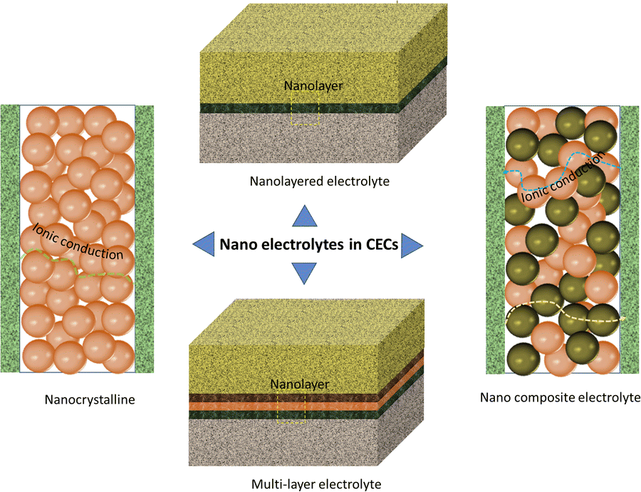 | ||
| Fig. 16 Nanotechnologies in the electrolytes of CECs. Plotted by the authors. | ||
Wet chemical synthesis routes are widely used for the syntheses of NPs because of their advantages in achieving uniform dissolution of metal ions and relatively low phase formation temperature of the aimed materials with nano size. A sol–gel combustion reaction is a typical strategy and has been commonly used toward the syntheses of nano-size powders, as reported in previous literature.258–261 For the samples obtained via this method, the particle characteristics will be influenced by several factors. Among them, the chelating agent is one crucial factor contributing to the morphology evolution of NPs. Osman et al. experimentally analysed the chelating agent size effect on the crystallization characteristics of BaCe0.54Zr0.36Y0.1O2−δ, using six different chelating agents.262 The final results indicated the difference in phase composition and morphology characteristics for the specimens obtained by different chelating agents. Wu et al. developed a flame-based gas-phase fabrication method.263 The combustion process was modified, by using a swirling spray flame burner. The primary particle size was about 20 nm, which was considered to be helpful for achieving an advanced electrolyte. More importantly, this method was proved to be affordable to scale up. Co-precipitation is another technical method that can be used for preparation of NPs. For example, Choolaei et al. presented experimental evidence of using ammonium tartrate as a precipitant for the synthesis of nanocrystalline Gd0.1Ce0.9O2−δ (GDC10) and Gd0.2Ce0.8O2−δ (GDC20).264 NPs with a uniform particle size of 10–30 nm was obtained. Wet chemical synthesis methods also demonstrated strong application potential for constructing functional interlayers in CECs. For instance, Lyu et al. used a hydrothermal approach to surficial modification of doped ceria, which was then employed as an electrolyte barrier layer for a zirconia electrolyte.265 Both Ro and Rp values were improved, evidencing the successful modification of the interlayer by a wet chemical route.
:6) heterostructure exhibited a PPD of 892 mW cm−2 at 550 °C. Rauf et al. found that, in Ce-doped BaCo0.2Fe0.3−xCexZr0.3Y0.1Tm0.1O3−δ (x = 0.1–0.2), the band structure alignment could be facilely regulated by controlling the Ce amount (Fig. 17b).275 A specimen doped with 20% Ce exhibited a dual conduction behaviour, with oxide-ion and protonic conductivities of 0.193 S cm−1 and 0.09 S cm−1 at 530 °C, respectively. At this temperature, a fuel cell with a BaCo0.2Fe0.2Ce0.2Zr0.3Y0.1Tm0.1O3−δ electrolyte achieved a PPD of 873 mW cm−2. A similar semiconducting behaviour can be found in Co-doped SrSnO3.276 An internal electric field was successfully built up, and the ionic transport was greatly improved.
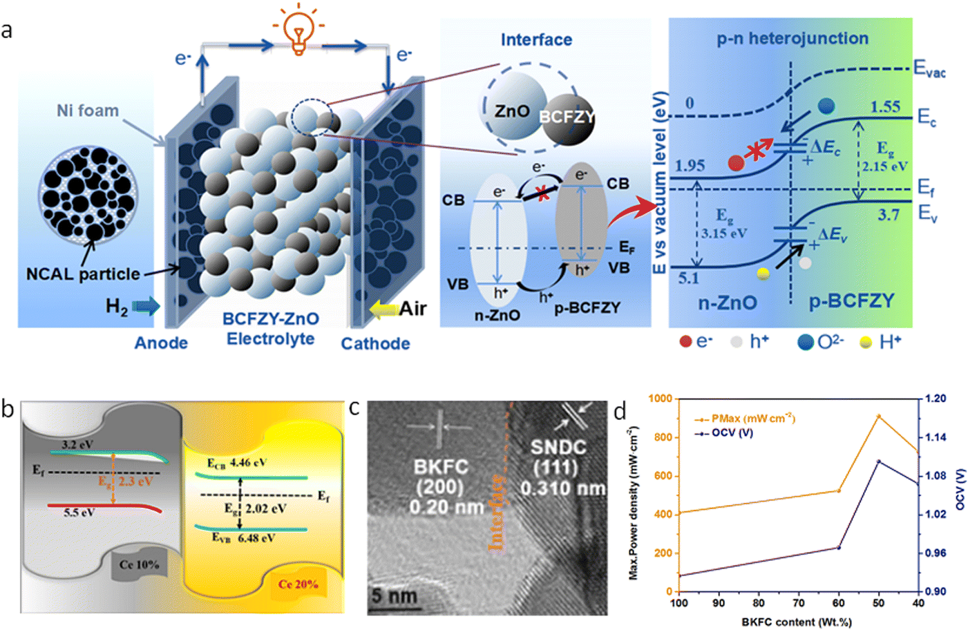 | ||
| Fig. 17 (a) Schematic sketch of a p–n heterojunction built at the BCFZY-ZnO interface and the as-proposed mechanism based on the illustration of the energy band alignment. Reproduced with permission from ref. 272. Copyright 2019, Springer Nature. (b) Schematic diagram of the energy band structures of BaCo0.2Fe0.2Ce0.1Tm0.1Zr0.3Y0.1O3−δ and BaCo0.2Fe0.1Ce0.2Tm0.1Zr0.3Y0.1O3−δ. Reproduced with permission from ref. 275. Copyright 2021, Elsevier. (c) A HR-TEM image of BKFC and SNDC. (d) PPD and OCV curves as a function of BKFC content. Reproduced with permission from ref. 277. Copyright 2022, Elsevier. | ||
Many literature supported that the energy band of doped ceria is suitable for construction of a built-in electric field with a great number of semiconductors. Tayyab et al. demonstrated that the energy band alignment between Sm0.2Ce0.8O2−δ (SDC) and LiNi0.8Co0.15Al0.05O2 matched well, and accordingly combined them together.278 An ionic conductivity as high as 0.12 S cm−1 was achieved at 520 °C, and a remarkable PPD of 0.735 W cm−2 was achieved at the same temperature. Liu et al. utilized p-type Ba0.9K0.1Fe0.5Co0.5O3−δ (BKFC) and n-type Sm0.075Nd0.075Ce0.85O2−δ (SNDC) and successfully built a p–n junction between them (Fig. 17c).277 An ionic conductivity of 0.14 S cm−1 was achieved and a PPD of 911 mW cm−2 was recorded at 550 °C (Fig. 17d). Liu et al. built a Schottky barrier in Gd0.15Ni0.05Ce0.8O2−δ (GNDC) and SnO2, and yielded a high hybrid conductivity of 0.220 S cm−1 at 550 °C.279 An OCV of 1.026 V and a PPD of 879.4 mW cm−2 were achieved at this temperature. It is interesting that although nano-sized semiconductor junctions have been widely investigated as electrolytes in SOFCs, very few literature about their application in electrolysis cells was reported. The main reason may be ascribed to the unique porous structure of the semiconductor-containing electrolyte that may not afford high working voltage and efficient gas separation in electrolysis mode.
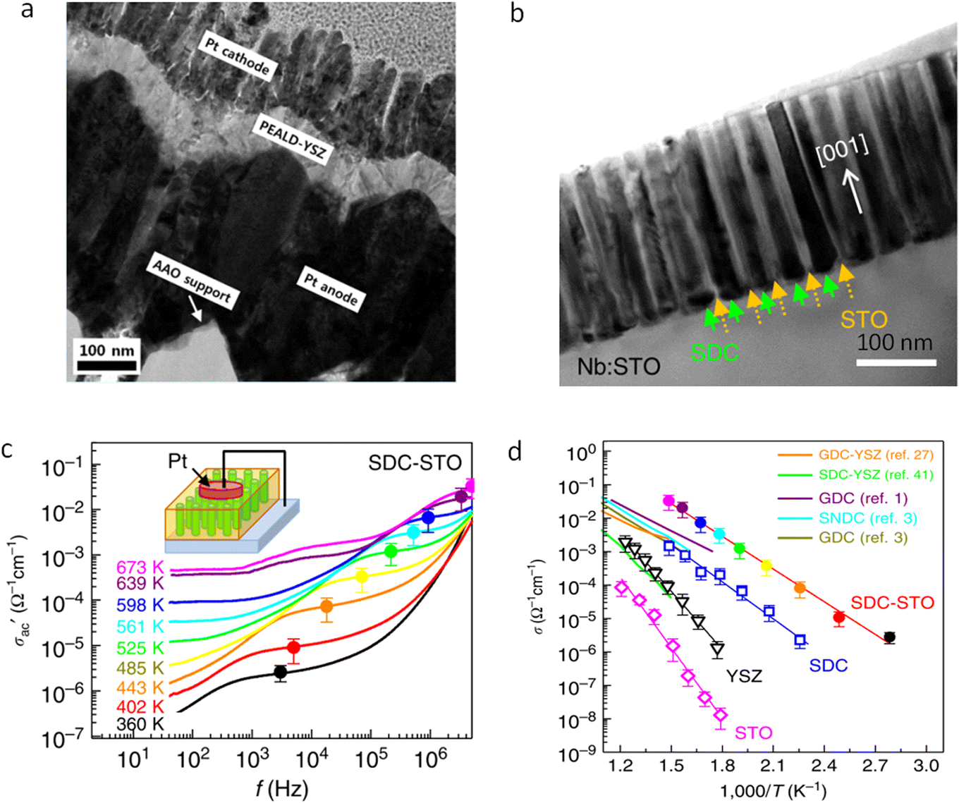 | ||
| Fig. 18 (a) HR-TEM image of an alumina oxide-supported cell structure containing a 70 nm-thick electrolyte. Reproduced with permission from ref. 283. Copyright 2015, American Chemical Society. (b) TEM view of SDC nanocolumns on the STO substrate. (c) Frequency dependence of the real part of ac conductivity as tested in the nano-scale SDC–STO film at different temperatures. (d) Temperature dependence of the conductivity of the SDC–STO film. Reproduced with permission from ref. 285. Copyright 2015, Springer Nature. | ||
In-depth research of the ionic transport behaviours would provide key information on the nature of the electrochemical reactions in ceramic materials. Yang et al. used the first-order reversal curve current–voltage method, which could be applied for local probing of ionic/electronic conduction associated with electrochemical reactions at a 10 nm scale in nano-scaffold SDC–STO membranes.285 It was considered as a practical geometry for energy device miniaturization, which was composed of highly crystalline vertical nanocolumns of doped ceria (Fig. 18b). As a consequence, the ionic conductivity was increased by tenfold higher than that of plain SDC membranes. By employing scanning probe microscopy, it was found that the ion transport channels were both confined to the interface and at SDC nanopillars (Fig. 18c and d). The corresponding results provided more confidence for realizing spatially localized rapid ion transport in oxides.
Till now, it remains a challenging task for fabrication of nano-thin perovskite oxide membranes, and very few research groups concentrated on the construction of ultrathin electrolyte layers with traditional ceramic technologies. The reason may be ascribed to the difficulties in densification of perovskite oxides at high temperature. Most perovskites used in CECs are composed of alkaline earth metal ions. The partial metal ion segregation, the grain crack, etc. make the structure fragile at high temperature. Therefore, there are still significant technical difficulties in efficient construction of a nano-thin perovskite membrane.
Due to partial reduction of Ce4+ to Ce3+, doped ceria works as a mixing conductor (O2− and e−) under reducing atmosphere and high temperature conditions, and will induce internal short circuiting when being used as an electrolyte material. To suppress internal electronic leakage, Myung et al. fabricated an ultrathin YSZ membrane as a blocking layer between the fuel electrode and the GDC electrolyte.291 They prepared four specimens with different sizes (0–200 nm). The OCV values were boosted to be around 1.1 V, for all the as-modified specimens. The cell with 100 nm-thick YSZ output the largest PPD. Sun et al. ingeniously employed internal Ba diffusion for in situ fabrication of a shell over SDC with a perovskite-type structure.292 TEM observation displayed a core/shell structure. Internal electronic leakage was found to be completely eliminated due to the perovskite-structured shell.
An et al. reported a novel strategy for fabrication of a thin-film three-dimensional (3D) SOFC architecture using the nanosphere lithography (NSL) technique.293 The ultrathin electrolyte membrane was interposed with a nano-sized catalytic interlayer. A PPD of 1.3 W cm−2 was achieved at 450 °C in a YSZ-supported SOFC, which was an ultrahigh power output for YSZ-based SOFCs at such an ultralow temperature, even comparable to the most outstanding results up to now. The authors believed that the decrease of ohmic and polarization resistances was caused by the combined effects of usage of an ultrathin electrolyte membrane, increased active areas by the 3D architecture, and enhanced catalytic activities facilitated by the ceria-based interlayers. This work provided valuable reference and practical significance that were very helpful for further design of high-performance SOFCs.
5.3 Nanotechnologies in air electrodes
Extensive efforts were made toward the improvement of air electrodes for CECs, especially in terms of catalytic activity and durability. Nanotechnologies have demonstrated their significant contributions to the development of CECs. Herein, different technology approaches toward NPs in air electrodes were discussed and analysed. Indeed, the combination between micro-size grains and NPs provided a new opportunity toward superior electrochemical reaction kinetics.294 However, to accurately address the working roles of NPs, recent nanoengineering approaches were categorized according to the number of nano-scale species, including nano-size particles and configurations, without taking into account of macro- and micro-scale grains. Therefore, in the following sections, single-phase NPs, biphasic NPs, triple-phase NPs, etc. imply the air electrodes containing single type of NPs, two and three types of NPs, etc., respectively, rather than taking into account of macro-/micro-scale particles in air electrodes.40,75:1 in ratio).296 Duan et al. reported Zr–Y co-doped BaCo0.4Fe0.4Zr0.1Y0.1O3−δ (BCFZY), and successfully achieved fabrication of a nanostructure using the traditional sintering process.297 They also demonstrated that a nanoparticulated BCFZY catalyst phase was obtained using an infiltration approach.18 A SOFC yielded a PPD of 455 mW cm−2 at 500 °C thanks to the boosted electrochemical reaction kinetics facilitated by surficial BCFZY NPs. Since Sm0.2Ce0.8O2−δ (SDC) was an oxygen ion conductor, Saqib et al. impregnated it into the air electrode and prepared a H+–O2−–e−-conducting catalytic electrode.298 A cell with decorated SDC exhibited a reduced Rp from 1.388 to 1.079 Ω cm2 in a symmetric configuration at 600 °C. Moreover, an increased current intensity of 1.76 A cm−2 of a modified cell vs 1.17 A cm−2 of the pristine cell was achieved at 700 °C and at an applied voltage of 1.5 V fed with the 20% steam–80% air mixture. While working in SOFC mode, the SDC-infiltrated PCFC exhibited an improved MPD due to infiltrated SDC. Saher et al. coated porous nano-particulate Gd2O3, CeO2, and GDC20 onto perovskite-type La0.58Sr0.4Co0.2Fe0.8O3−δ (LSCF) ceramics.75 As shown in Fig. 19b and c, the oxygen surface exchange kinetics of the specimens were experimentally evaluated at 700–900 °C, followed by the pO2-step varying in the range of 0.2-0.4 atm. Dchem values remained stable for the coated samples, while the apparent level of kchem was likely to change with the loading mass and the ionic conductivity of the decorated phase (Fig. 19b). The authors then concluded that partial coverage by Gd2O3 or CeO2 reduced the kchem values due to their inert non-ionic conductivity inducing surficial blocking effects. Nevertheless, the situation would be much different for GDC20. Uncompleted coverage of LSCF with GDC20 NPs apparently enhanced kchem up to a factor of 6 relative to the untreated sample. The results from the pulse isotope exchange test supported that the surface exchange reaction on bare LSCF was strongly limited by dissociative adsorption of O2. An exchange oxygen ion between LSCF and GDC20 was conceived, as revealed in Fig. 19c. In turn, LSCF was able to be infiltrated onto the GDC backbone with a LSCF-containing precursor, forming LSCF NPs with small size.299 In order to improve CO2 electrolysis performance, Huang et al. infiltrated Ce0.9M0.1O2−δ (M = Fe, Co, Ni) co-catalysts into the La0.6Sr0.4Fe0.5Cr0.5O3−δ–Gd0.2Ce0.8O2−δ (LSCrFe–GDC) air electrode.300 The Ce0.9Co0.1O2−δ infiltrated cell outperformed the best performance at 1.5 V and 800 °C (0.652 A cm−2). ElS combined with DRT analyses displayed that both adsorption and dissociation processes of CO2 at TPBs were facilitated by co-catalysts.
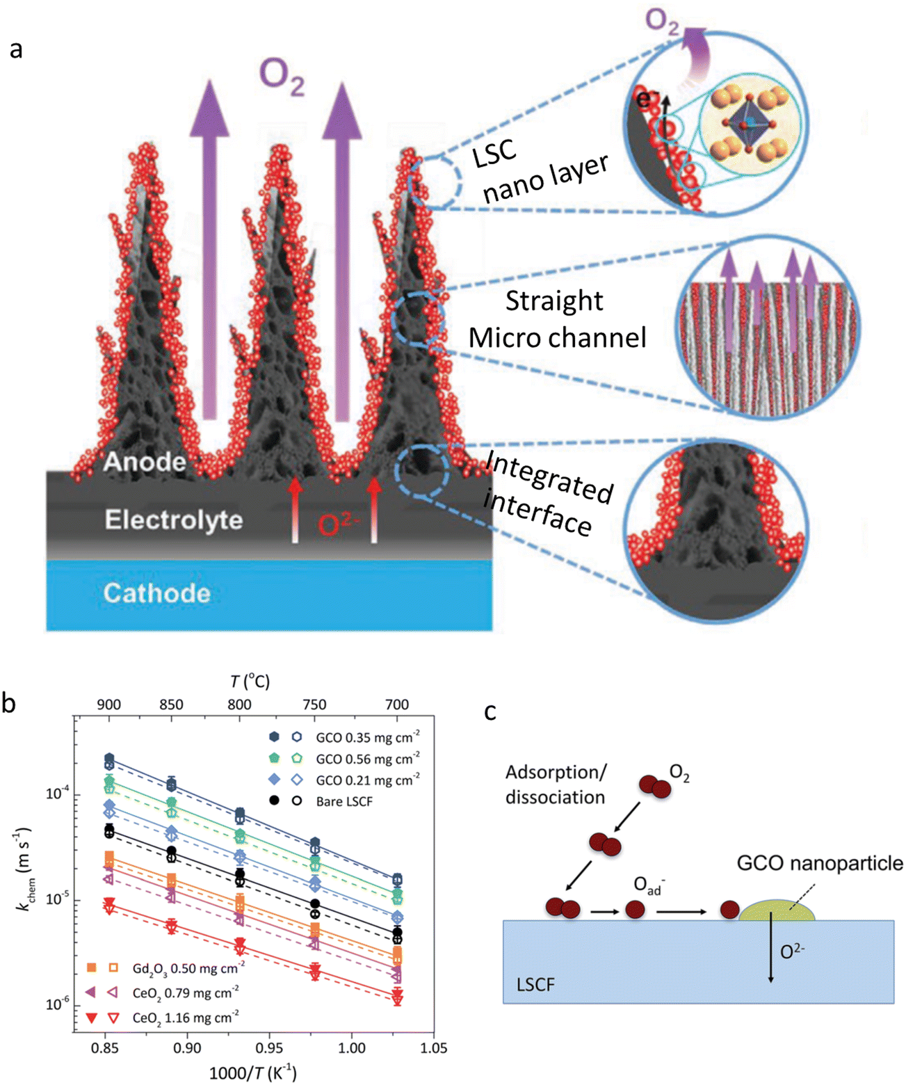 | ||
| Fig. 19 (a) A sketch of the particular SOEC with a nano/micro-channel air electrode. Reproduced with permission from ref. 40. Copyright 2022, John Wiley and Sons. (b) Arrhenius plots of kchem for pristine LSCF and impregnated specimens. (c) Oxygen exchange mechanism on GDC20 NP-coated LSCF. Reproduced with permission from ref. 75. Copyright 2017, the Royal Society of Chemistry. | ||
Other typical oxides are affordable for construction of active NPs in CECs. For example, a Pr6O11 infiltrated LaNi0.6Fe0.4O3/Ce0.9Gd0.1O2 (LNF/CGO) composite, demonstrated a low Rp value of 0.074 Ω cm2 at 600 °C, as reported by Khoshkalam et al.301 The infiltration approach inspired Ge and co-workers. They incorporated Pr6O11 NPs into (La,Sr)MnO3−δ (LSM), La0.6Sr0.4Co0.2Fe0.8O3−δ (LSCF) and La0.6Sr0.4CoO3−δ (LSC).302 The Rp value of LSM was reduced to be about ten percent of its original value, while for LSCF and LSC, the Rp values were greatly reduced in the range of 600–800 °C as well. Li and colleagues conducted an infiltration treatment of active Y0.25Bi0.75O1.5 into the LSCF electrode.303 An ultralow temperature of 600 °C was experimentally demonstrated suitable for the generation of a pure material, due to the low phase formation and melting points of bismuth oxides. Moreover, NiO was used in co-catalysts through infiltration. Lee et al. impregnated nickel nitrate solution into the air electrode, and the size of NiO components was observed to be 10–50 nm.304 A low polarization resistance and a high PPD of 780 mW cm−2 were yielded at 600 °C.
Infiltration of one perovskite into another, forming a composite perovskite, is effective for the electrochemical activity improvement. Wang et al. infiltrated LaCoO3 (LCO) into the BaZr0.8Y0.2O3−δ (BZY) scaffold.305 Porous BZY backbones were first obtained, and LCO NPs with a size of 50–100 nm were then achieved through the impregnation method. A Rp of 0.56 Ω cm2 was obtained at 600 °C, together with a superior long-term sustainability at 600 °C for 900 h. Meanwhile, they infiltrated Ba0.5Gd0.8La0.7Co2O3−δ (BGLC) into the BaZr0.8Y0.2O3−δ (BZY20) backbone.306 BGLC was a triple-conducting double perovskite. Then the introduction of BGLC could be helpful for improving the electrochemical reactions of the electrode, including the diffusion of adsorbed oxygen, oxygen reduction, charge transfer, etc. Huang et al. prepared a La0.6Sr0.4CoO3−δ (LSC) decorated La0.6Sr0.4Co0.2Fe0.8O3−δ–Ce0.9Gd0.1O2−δ (LSCF–GDC10) composite air electrode for low-temperature SOFCs by the infiltration method.307 The infiltration process led to intrinsic catalytic activity together with high surface area densities (Fig. 20a). As a consequence, the PPDs of the modified cell were doubled, as compared to the pristine ones. Furthermore, active and exceptional stability testing results as long as over 1300 h were obtained at 600 °C, suggesting high catalytic ability and sustainability of the hybrid air electrode. More perovskites are proved to be effective additives. For example, according to Vøllestad’ research on proton ceramic electrolysers, the air electrode layers were infiltrated with a suspension of Ba0.5Gd0.8La0.7Co2O6−δ NPs (<100 nm) for achieving advanced electrode activity.308 Ba0.5Gd0.8La0.7Co2O6−δ was also able to be employed as an appropriate functional phase while being infiltrated into the BaZr0.7Ce0.2Y0.1O3−δ scaffold.309 Namgung et al. reported a modification strategy to the infiltration process.310 In their work, the introduction of cetrimonium bromide (CTAB) amino acid (glycine) led to infiltration of individual Sm0.5Sr0.5CoO3−δ (SSC) particles on the electrode backbone, forming a 3D network. Consequently, a button cell demonstrated an enhanced property with an output of 1.57 Wcm−2 at 700 °C, together with a 100 h durability under 1 A cm−2. In addition, SSC was also employed for infiltration in the La0.7Sr0.3FeO3−δ–BaZr0.1Ce0.7Y0.2O3−δ (LSF–BZCY) composite to improve the electrochemical performances of the air electrode, as reported by Chen et al.311 A coating of 15 wt% SSC was found to be suitable for improving the overall cell performance.
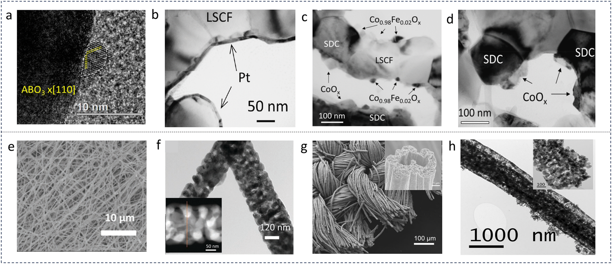 | ||
| Fig. 20 (a) HR-TEM observation of LSC infiltrated particles. Reproduced with permission from ref. 307. Copyright 2018, Elsevier. (b) TEM image of a dense Pt (7 nm)-coated LSCF backbone. (c) TEM pattern of the CoOx coating, leading to discrete (Co0.98Fe0.02)Ox. (d) TEM observation of discrete CoOx nanograins on the surface of mixed conductor SDC. Reproduced with permission from ref. 312. Copyright 2021, Elsevier. (e) SEM pattern of green fibers before calcination. (f) Typical TEM and STEM (inset) images focusing on LSCF fibers. Reproduced with permission from ref. 313. Copyright 2016, John Wiley and Sons. (g) and (h) SEM images of the electrode mesh with low- and high-magnification. Reproduced with permission from ref. 27. Copyright 2020, Springer Nature. | ||
Co/Fe-based perovskites, such as BaCo0.4Fe0.4Zr0.1Y0.1O3−δ (BCFZY), were usually not stable under a harsh humid atmosphere, and showed high reactivity with H2O and CO2.314 However, the reaction may be partially reversable under particular conditions, and hence this particular behaviour can be used for conversion of derived BCFZY NPs on an electrode surface above 800 °C. In a YSZ-based SOFC, a PPD of 1.61 W cm−2 was obtained at 700 °C. Meng also observed the in situ regeneration of BCFZY NPs on BCFZY backbones through a reaction with H2O and CO2, and characterized it as the air electrode in electrolysis mode.315 The current density increased from 0.30 A cm−2 to about 1.12 A cm−2 within about 400 h at 600 °C and 1.3 V.
Traditionally, the infiltration procedure toward a nanostructured air electrode is tedious, which often requires several periodic infiltration treatments and high-temperature calcination cycles. Rehman and co-workers provided a facile and scalable urea-based ultrasonic spray infiltration method for fabrication of nano-scale La0.6Sr0.4Co0.2Fe0.8O3−δ (LSCF) for SOFCs.316 It was experimentally proved that, by using urea as a precipitating agent, a single calcination procedure was enough for the conversion of the infiltrated phase into a desirable catalyst phase. Even a low temperature of calcination (≤900 °C) could produce a durable SOFC. While combining with the ultrasonic spray technique, the urea-assisted impregnation could be easily scaled up for achieving a desirable electrode area. The cell was then analysed by a long-term durability test for 1200 h, and no signs of degradation were found, demonstrating the effectiveness of the advanced technology in production of durable SOFCs. This research also proposed an alternative way toward commercial fabrication of a durable nanostructured air electrode for SOFCs. Chen et al. proposed a feasible strategy to apply a dense coating layer on a mixed electrode, which was utilized for improving the total conductivity and durability of a SOFC air electrode.312 As shown in Fig. 20b–d, Pt or CoOx was used as the co-catalyst for a LSCF/SDC air electrode, realized by the ALD coating strategy. The decorated layers facilitated a strong interaction between the cocatalysts and the backbones. The Pt coating layer was found to be conformal on LSCF grains, while discrete Pt was observed on SDC. For the sample coated by CoOx, the conformal layer turned to be discrete, both on LSCF and SDC grains. Anyway, ALD coating of cocatalysts reduced the cell ohmic resistance. Tailoring infiltrated solution with coordinating organic agents could further reduce the size of NPs. During metal–ion infiltration, Błaszczak et al. investigated the influence of β-cyclodextrin on metal NPs.317 They found that smaller metal oxides could be obtained on the substrate surface, resulting in increased catalytic activity and enhanced durability of the composite catalysts. To date, infiltration has been widely used in the research of air electrodes. Some classical candidates, such as BSCF,318etc., can be used for infiltration. For more critical data, a collection of the literature data reported in the last 5 years was compiled and compared with each other, as shown in Tables 1–3.
Apart from infiltration, more efforts were devoted toward effective fabrication of NPs. Pei et al. reported a new self-reconstruction phenomenon in Ba0.9Co0.7Fe0.2Nb0.1O3−δ (BCFN), through a water-promoted surface corrosion process.32 The BCFN electrode was naturally converted into a Nb-rich BCFN electrode (µm scale) decorated with Nb-deficient BCFN NPs. In a R-PCEC, the air electrode achieved good performances at 650 °C, such as, a PPD of 1.70 W cm−2 in fuel cell mode and a current density of 2.8 A cm−2 at 1.3 V in electrolysis mode. Chen et al. prepared LSCF nanofibers using an electrospinning strategy, as shown in Fig. 20e and f.313 The diameters of nanofibers were about 50 nm with a pore size of around 50 nm, producing high surface areas for the ORR and high ionic conduction enabled by the fiber structure. Then the air electrode equipped with LSCF nanofibers was tested in a SOFC. According to the experimental results, LSCF nanofiber-equipped air electrodes displayed lower Rp and smaller activation energy for the ORR with respect to a commercial LSCF powder or the nano-LSCF powder which was obtained through the crushed fibres by grinding. The unique electrode architecture favourable to efficient mass/charge transport was considered as the key factor for influencing ORR kinetics, as reflected by DRT analyses of the EIS results. Geometric modelling and simulations suggested that longer and thinner fibers facilitated both mass and charge transport. A single cell with LSCF nanofibers exhibited better performance than the cells with the electrode from commercial LSCF powder or the crushed LSCF nanofibers. Moreover, the cells with a nanofiber electrode displayed excellent sustainability at a constant voltage of 0.7 V for about 450 h at 600 °C when being fed with wet H2.
Another constructive work for advanced PCEC air electrodes was contributed by Ding et al.27 As presented in Fig. 20g and h, a self-architectured mesh-like electrode was synthesized in order to build a highly porous frame for fast mass transport. A nanofiber-structured triple conducting oxide of PrNi0.5Co0.5O3−δ (PNC) was developed as the air electrode, presenting superior electrochemical performance at 400–600 °C. As for the results, the self-sustainable and reversible operation was successfully accomplished through converting the generated hydrogen of the SOEC to electricity by the SOFC without any H2 supply. The outstanding electrocatalytic activity was attributed to the excellent proton conduction and remarkable hydration behaviour, as claimed by the authors.
In addition, substitution of electrode compositions with anti-sintering elements such as Zr, Mo, W, etc. was effective in reducing the particle size, and can be used to realize the generation of NPs, according to our knowledge. Then NPs might be synthesized at high temperature. In this regard, a traditional sol–gel method is available for nano-sized air electrodes. Lei et al. prepared Sr2Fe1.5Mo0.5O6−δ (SFM) and evaluated its electrochemical properties as the air electrode for SOECs.319 The electrolyte material was BaZr0.8Y0.2O3−δ (BZY), which was much stable in a H2O-containing atmosphere. SFM powders were synthesized through a glycine and citric acid assisted combustion method. To obtain pure SFM, the as-synthesized ash was heat-treated at 1050 °C for 5 h. BZY was mixed with SFM with a ratio of 1:1 to prepare a composite electrode. SEM observations demonstrated that nano-scale SFM–BZY was successfully yielded. Additionally, high SOEC performance with a current density of 0.21 A cm−2 and a faradaic efficiency of 63.6% were achieved at 600 °C.
One critical challenge impeding the development of reversible protonic CECs (R-PCECs) is the sluggish ORR and OER kinetics at the air electrode, and compositional/structural reconstruction though nanotechnologies provided alternative pathways toward a superior air electrode. Xu et al. synthesized a PrBaCo1.6Fe0.2Nb0.2O5+δ air electrode, observed exsolved Nb-deficient PrBaCo1.6Fe0.2Nb0.2−xO5+δ NPs on the backbone, and made electrochemical assessment both in fuel cell and electrolysis cell modes.320 The in situ formed NPs and parent perovskite benefited high catalytic activity and durability of the electrode toward efficient ORR and OER at 650 °C, achieving a PPD of 1.059 W cm−2 (fuel cell), a current density of 2.148 A cm−2 at 1.3 V (electrolysis cell), and superior cyclability at ±0.5 A cm−2 in dual mode for 200 h. He et al. reported a one-pot synthesis method in self-constructing NPs for R–PCECs.321 They first used Ba2Co1.5Mo0.25Nb0.25O6−δ (BC1.5MN) as the precursor. After being sintered at high temperature, BC1.5MN decomposed into BaCoO3−δ (BCO, 45 wt%, a single perovskite) and Ba2−xCo1.5−xMo0.5Nb0.5O6−δ (BCMN, 55 wt%, a double perovskite). In this composite, only BCO was observed to be crystalized into NPs with a size of 50–100 nm. Its high oxygen ion and electronic conductivities boosted ORR and OER performances. At 650 °C, the cell achieved a PPD of 1.17 W cm−2 and a current density of 2.04 A cm−2 at 1.3 V. Zhu et al. reported a new compound of Ba0.8Gd0.8Pr0.4Co2O5+δ, which can naturally reconfigure a double-perovskite Ba0.8Gd0.8−xPr0.4Co2−yO5+δ (BGPC) and single-perovskite GdxCoyO3−δ (GCO) NPs on the BGPC surface.322 As a result, the GCO-decorated BGPC electrode displayed a low Rp of 0.136 Ω cm2 at 650 °C in a symmetrical cell. When being employed as an air electrode, the cell displayed a PPD of 0.909 W cm−2 in a button fuel cell and a current density of 2.336 A cm−2 at 1.3 V as tested in an electrolysis cell. Niu carried out interesting experimental research on Pr0.5Ba0.5CoO3−δ.323 While being applied as the infiltration precursor on LSCF, a thin film with a composition of Pr1−xBaxCoO3−δ and exsolved BaCoO3−δ NPs were obtained, after sintering the precursor at 800 °C for 2 h in air. The modified surface remarkably enhanced the LSCF air electrode electrochemical properties with an improved surface oxygen exchange rate, superior surface proton diffusion, and rapid H2O and O2 dissociation. At 600 °C, Rp of the catalyst coated LSCF air electrode was reduced by a factor of 25 (from 1.09 to 0.043 Ω cm2) in air, together with a lower degradation rate. Consequently, at 600 °C, a single cell with a modified LSCF electrode exhibited a high PPD of 1.04 W cm−2 in a fuel cell and a remarkable current density of 1.82 A cm−2 at 1.3 V in electrolysis mode. In addition, Chen et al. employed BaCoO3−δ (BCO) NPs as the active sites for electrochemical reactions. They coated the Ba(NO3)2 solution onto the PrBa0.8Ca0.2Co2O5+δ (PBCC) backbone, and finally obtained BCO NPs.324 The PPD of the fuel cell was improved from ∼0.85 to ∼1.15 W cm−2 at 750 °C, facilitated by the surface modification. Then, Zhou et al. from Prof. Liu’ group reported a PrBa0.8Ca0.2Co2O5+δ air electrode decorated with BaCoO3−δ NPs and being annealed in air with oversaturated H2O (Fig. 21).325 The cell utilizing the as-designed electrode displayed minimal polarization resistance of about 0.24 Ω cm2 at 600 °C, as well as high stability against 3–50% humidified air. A high-performance R–PCEC using PBCC–BCO exhibited a PPD of 1.06 W cm−2 in a fuel cell and a current density of 1.51 A cm−2 at 1.3 V in an electrolysis cell at 600 °C. More importantly, the RPCECs demonstrated an extremely strong durability over 1833 h as tested in electrolysis mode.
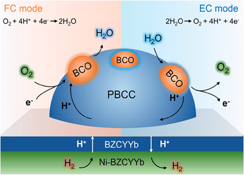 | ||
| Fig. 21 A schematic sketch of an R-PCEC with a BCO-anchored PBCC air electrode operated in different modes. Reproduced with permission from ref. 325. Copyright 2021, American Chemical Society. | ||
5.3.2.1 Fluorites coupled by metal/metal oxides. Different types of functional NPs can be combined by smart technical methods enabling elevated catalytic activities, which makes active catalysts attainable but suppresses the growth of a fragile catalyst. Jeon et al. combined NP infiltration and ALD nanotechnologies. The surficial composition and structure of LSCF were then improved.326 In an experiment, Ag NPs were first dispersed onto the LSCF air electrode by infiltration. After that, the air electrode was uniformly covered by a thin ZrO2 nanolayer, preventing the agglomeration of NPs and suppressing Sr segregation (Fig. 22). As a result, the Ag/ZrO2-decorated LSCF displayed an Rp as low as 0.085 Ω cm2 at 650 °C. As we know, undoped ZrO2 is inert under most conditions, and thus a delicate technical approach should be developed in order to achieve a final balance between the catalytic activities and material stabilities. For example, Gong et al. prepared a 5 nm-thick ZrO2 film on the La0.6Sr0.4CoO3−δ surface by the ALD method.327 An exceptional sustainability of 4000 h was achieved at 700 °C, demonstrating excellent lifespan with strong suppression of Sr-segregation across particle surfaces. Zhang et al. infiltrated Co ions into the BaZr0.4Ce0.4Y0.2O3−δ (BZCY442) backbone using Co(NO3)2 solution with a concentration of 0.8 mol L−1.295 A 3D core–shell structure and H+/O2−/e−-conducting electrode shell composed of cubic Ba(Zr0.4Ce0.4Y0.2)1−xCoxO3−δ (micro scale), cubic nano-size spinel Co3O4 and cubic fluorite (Ce, Zr, Y)O2−δ NPs was fabricated in situ. A Rp value of 0.094 Ω cm2 was obtained at 650 °C in 3% H2O-containing air. In this work, low ionic resistance of the cell was achieved due to the nano/micro-sized core–shell structure.
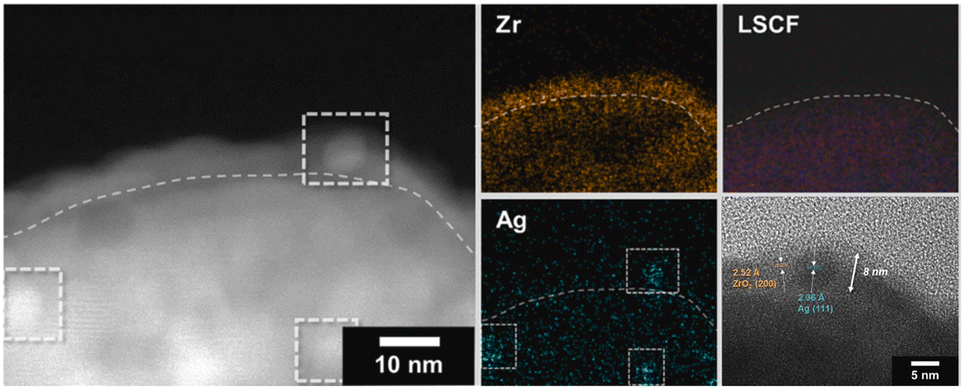 | ||
| Fig. 22 HAADF-STEM, EDS mapping results, and HR-TEM image of the Ag/ZrO2 modified LSCF nanocomposite. Reproduced with permission from ref. 326. Copyright 2023, Elsevier. | ||
5.3.2.2 Perovskite coupled by metal oxide. As for the air electrodes composed of two or more types of NPs, the crystallization kinetics can be reduced due to the efficient spatial separation between different compositions. For example, in one recent work reported by Liu and colleagues, quasi-stable nano-sized composites were prepared using a one-pot strategy, evidencing the effect of different phase mixtures on the suppression of grain growth.328 Chen et al. provided an effective way in dramatically boosting the ORR kinetics and durability of the La0.6Sr0.4Co0.2Fe0.8O3−δ (LSCF) air electrode through a hybrid catalyst modification method.329 The coating layer was thin-film PrNi0.5Mn0.5O3−δ (nano-size PNM). PrOx NPs were exsolved out, concurrently. At 750 °C, the hybrid catalyst-decorated LSCF displayed an Rp of 0.022 Ω cm2, about 1/6th of that of the bare LSCF (about 0.134 Ω cm2). The PPDs and durability of a fuel electrode-supported cell were both successfully improved. The authors then combined the experimental analyses with DFT calculations, and indicated that the oxygen-vacancy-rich surfaces of PrOx NPs greatly accelerated the electron transfer rate in ORR processes whereas the thin PNM film worked as a positive layer that greatly facilitated oxide-ion transport capability and strongly improved LSCF surface stability. Interestingly, exsolved PrOx NPs induced a Pr deficiency in the parent PNM coating layer, and the non-stoichiometric structure demonstrated a smoothly curved vacancy trajectory, while the stoichiometric lattice exhibited a strong interaction between the vacancies and the neighbouring ions, as comparably given in Fig. 23a and b. In another literature report from the same research group, the effects of surficial modification on ORR enhancement were further identified.330 To address the poisoning mechanism of contaminants, for instance, Cr species, Chen et al. carried out a unique operando surface enhanced Raman spectroscopy study on the La0.6Sr0.4Co0.2Fe0.8O3−δ (LSCF) electrode. An effective infiltration pathway for improvement of the tolerance to contaminants poisoning was proposed. A composite catalyst coating was developed, consisting of the PrNi0.5Mn0.5O3−δ nano-size film and exsolved PrOx NPs, as sketched in Fig. 23c. The coating species was catalytically active to the ORR but was sluggish while encountering contaminant poisoning, which were concluded according to the analyses of EIS curves in Fig. 23d. As shown by an accelerated Cr poisoning test result, the modified cells displayed a remarkable PPD (0.71 Wcm−2), as well as a dramatically low degradation rate of 0.0434% h−1 at 0.7 V, much lower than those of the specimen with an unmodified electrode. These results gave rise to direct evidence that surface modification toward targeted co-catalysts was an effective strategy for alleviating electrode degradation caused by contaminations. J.A. Loureiro et al. fabricated a nano-scale La0.6Sr0.4Co0.2Fe0.8O3−δ (LSCF)–Ce0.8Sm0.2O1.9 (SDC) composite through a one-step microwave-assisted combustion synthesis pathway.133 A good distribution of LSCF and SDC NPs with a diameter of about 100 nm was observed although the samples were calcined at a high temperature of 950 °C. The polarization resistance was improved in comparison with the samples synthesised through traditional techniques in accordance with the impedance spectroscopy results. Li et al. prepared La0.5Ba0.25Sr0.25Co0.8Fe0.2O3−δ (LBSCF) nanofibers using the electrospinning technique by incorporating RuO2 into the nanofibers, and then analysed the charge transfer dynamics in RuO2/perovskite nanohybrids.331 In this system, LBSCF was a typical electron and oxygen ion mixed conductor. Due to the addition of RuO2, the Co–O affinity was strengthened across the LBSCF/RuO2 junction, which facilitated the diffusion of bulk O to the junction. Furthermore, RuO2 favoured delocalized transport in the metal–oxygen π* band, as theoretically demonstrated in Fig. 24a and b, and possessed an excellent capability for oxygen storage and release, making the switching possible between n-type and p-type conduction in RuO2. Xu and the co-authors prepared a La0.6Sr0.4Co0.2Fe0.8O3−δ (LSCF)–Ce0.8Sm0.2O1.9 (SDC) composite by impregnation of LSCF solution into the porous SDC backbone.332 Both oxides crystalized into NPs. The relationship between the sintering temperature (800–1200 °C) and the oxygen reduction reaction mechanism was systematically investigated. The average LSCF particle size remarkably increased with the increasing temperature, and a nanoscale size of about 50 nm was maintained for the sample being calcined at 800 °C for 4 h. For the electrode sintered at 800 and 900 °C, the dominant ionic resistance in the medium frequency range was clarified and O2−bulk diffusion was found to be the rate-determining step. When the temperature increased, the low frequency arc became obvious, as concluded from the impedance spectral analyses, authenticating that the electrode process is limited by the step of the oxygen ion transfer at the electrode/electrolyte interface.
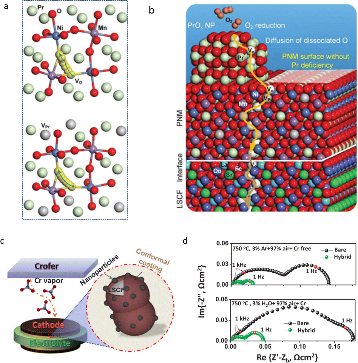 | ||
| Fig. 23 (a) DFT simulation patterns of the trajectory of oxygen vacancies without/with Pr deficiencies. (b) A sketch of the ORR on hybrid PrOx/PNM-coated LSCF and the bulk transport of oxygen vacancies. Reproduced with permission from ref. 329. Copyright 2017, The Royal Society of Chemistry. (c) A schematic showing a Cr-tolerant LSCF with a co-catalyst coating. (d) EIS of pristine LSCF and the coated LSCF as tested in symmetrical cells at 750 °C in different atmospheres. Reproduced with permission from ref. 330. Copyright 2018, Elsevier. | ||
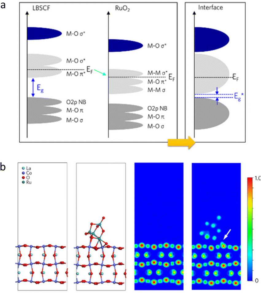 | ||
| Fig. 24 (a) Schematic band diagrams before and after the incorporation of RuO2 on LBSCF. Cyan arrow indicating the direction of internal charge transfer from Co 3d to Ru 4d states. (b) The structure of LaCoO3 and LaCoO3/RuO2, and their differences in electron densities. Reproduced with permission from ref. 331. Copyright 2019, Elsevier. | ||
5.3.2.3 Perovskite coupled by carbonate. Through infiltration treatment, Niu et al. coated LSCF with multi-phase Ba1−xCo0.7Fe0.2Nb0.1O3−δ (BCFN) and BaCO3, which can be considered as a typical example for a perovskite-carbonate composite nanocatalyst.333 The ORR activity and sustainability of the coated cell were proved to be improved, as simulated by the DFT method and shown in Fig. 25a and b, with a Rp of 0.048 Ω cm2 at 650 °C. As shown in the accelerated Cr-poisoning test results, the degradation rate of the coated electrode was 10−3 Ω cm2 h−1 (0.59% h−1) over 200 h at 750 °C, only 1/5th of the same parameter recorded using a bare LSCF electrode. Moreover, the modified cell demonstrated a dramatically enhanced power density of 1.4 W cm−2 at 750 °C, while the uncoated cell exhibited a PPD of 0.67 W cm−2.
 | ||
| Fig. 25 (a) Investigation of the energy profile for the ORR on a BCFN (010) surface. (b) Optimized structures and adsorption energies of CrO3 on different surfaces. Reproduced with permission from ref. 333. Copyright 2021, John Wiley and Sons. | ||
5.3.2.4 Perovskites combined with another perovskite. Nano-particulate perovskites have been proved to be suitable for providing active sites while being used as air electrodes in CECs. Therefore, through combing different perovskites, advanced CECs can be expected. Shin et al. proposed a self-assembled nanocomposite with a nominated composition of Ba0.5Sr0.5(Co0.7Fe0.3)0.6875W0.3125O3−δ (BSCFW) via a solid state synthesis method. The final products consisted of a B-site cation ordered double perovskite and a disordered single perovskite.334 The particle size was greatly reduced due to W doping, and was apparently identified to be on the nanoscale. Chemical stability of the cell was increased by the W dopant as well. Then Hu et al. investigated its catalytic performance in a PCFC.335 When being sintered at high temperature, the precursor crystalized into two perovskites, confirming well the aforementioned work. When used as an air electrode, BSCFW displayed thermodynamic protonic behaviour with a desired proton defect formation enthalpy of ΔH = −35 ± 7 kJ mol−1, which was comparable to those of most proton conductors. A cell equipped with a BSCFW electrode presented a Rp value of 0.172 Ω cm−2 at 600 °C and a PPD of 582 mW cm−2. Kim applied Ba0.5Sr0.5Co0.6Fe0.2Zr0.1Y0.1O3−δ (BSCFZY) as a precursor toward self-assembly of a dual-phase composite electrode.336 Co-rich and Zr-excessive phases with the chemical compositions of Ba0.5Sr0.5Co0.7Fe0.2Zr0.07Y0.03O3−δ and Ba0.6Sr0.4Co0.3Fe0.2Zr0.4Y0.1O3−δ were identified, and their ratios were quantitatively determined to be 88.1% and 11.9%, respectively. Meanwhile, the researchers claimed that the first compound facilitated the electrocatalytic activity, while the latter one acted as the supporting skeleton, forming a synergistic effect between Co- and Zr-excessive perovskites, as experimentally shown in Fig. 26a and b. An extremely low ASR of 0.013 Ω cm2 was obtained at 650 °C, evidencing the superiority of the one-pot synthesis method in fabricating biphasic composites. Inspired by a similar idea, Tong et al. designed a BaCexFe1−xO3−δ (x = 0.36, 0.43, and 0.50) compound which demonstrated natural crystallization behavior of two different nano-scale perovskites.337 Among these materials, BaCe0.36Fe0.64O3−δ (BCF36) was found to be an advanced electrode for PCFCs, yielding a PPD of 1.525 W cm−2 at 700 °C, due to its superior ionic and electronic conductivities caused by the appropriate chemical compositions. Very interestingly, a twin perovskite with a precursor composition of BaCe0.5Fe0.5O3−δ was designed by Zhao et al. and successfully used for syntheses of cubic and orthorhombic perovskites, while the cubic perovskite was observed to be reduced into orthorhombic oxide in dry 5 vol% H2, which would change their conduction properties.338 Shi et al. reported that through regulating the A-site metal ion ratios of LaSrxCo1.5Fe1.5O10−δ (x = 2.0–3.0), nanocomposites with different weight ratios of R–P and single perovskite (S–P) could be controllably prepared, via a one-pot strategy.339 A synergy was created between R–P and S–P NPs, generating favorable ORR activity in contrast to bare R–P and S–P oxides. Moreover, such a synergy effectively enhanced proton conductivity and led to a reduced TEC value of the electrode when being used in a BZCY172-based cell.
 | ||
| Fig. 26 (a) 3D atomic map of BSCFZY visualized by atom probe tomography (APT). (b) Atom-scaled identification of Co-rich BSCFZY and Zr-rich BSCFZY. Reproduced with permission from ref. 336. Copyright 2022, The Royal Society of Chemistry. | ||
 | ||
| Fig. 27 (a) HR-TEM observations of the SCFN2 sample. (b) Arrhenius curves of the ASR values in a symmetrical cell configuration equipped with electrodes of SrFeO3−δ (SF), SCFN1, SCFN2, and SCFN3. Herein, Sr0.9Ce0.1Fe1−xNixO3−δ (x = 0.1, 0.2, 0.3) series were abbreviated as SCFN1, SCFN2, and SCFN3, respectively. Reproduced with permission from ref. 31. Copyright 2020, John Wiley and Sons. | ||
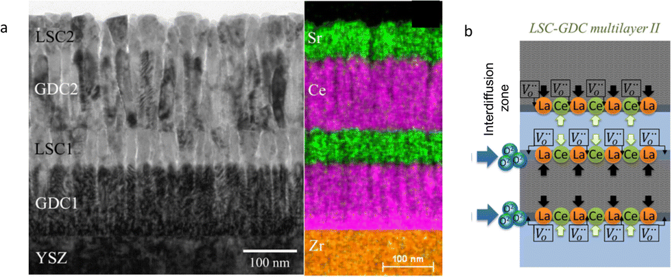 | ||
| Fig. 28 (a) A TEM image of the LSC–GDC multilayer on the YSZ substrate. (b) A schematic illustration demonstrating the metal ions interdiffusion occurred at LSC–GDC interfaces and the generation of oxygen vacancies. Reproduced with permission from ref. 344. Copyright 2018, Elsevier. | ||
Thermal and chemical mismatch between the electrolyte and the air electrode layers remains to be a challenging issue in CECs, hindering their wide commercialization. A nano engineering approach is considered as an effective way for alleviating the detrimental effect caused by the mismatch. Choi et al. coated a dense PrBa0.5Sr0.5Co1.5Fe0.5O5+δ (PBSCF) film (about 100 nm) on the BaZr0.4Ce0.4Y0.1Yb0.1O3−δ (BZCYYb4411) electrolyte via PLD.347 Due to the high proton permeability of PBSCF and alleviation of thermal mismatch between different layers, the cell exhibited an ultrahigh PPD (500 mW cm−2) at 500 °C. Accordingly, they provided a new concept on realizing thermo-mechanical compatibility between the electrolyte and electrode layers.
Mesoporous materials, a special architecture composed of NPs and nanopores, are characterized by their high specific surface areas, and can be applied to enhance the electrochemical reaction kinetics of an air electrode. Chen carried out an experimental research on a ZrO2 coated La1−xSrxMnO3−δ/YSZ (LSM/YSZ) backbone employing ALD and thermal treatment.351 Nano-size mesopores were formed, as observed in Fig. 29a, making the entire electrode surface open for gas penetration with high ionic conductivity and electrochemical activity. The nano-ionic network was found to be extremely stable after electrochemical operation between 650 and 800 °C for 400 h. A templating approach has been successfully employed in the fabrication of other mesoporous perovskites that can be used as electrodes in CECs.352 In another work, Hernández et al. synthesized a mesoporous GDC20 scaffold (Fig. 29b), and infiltrated La0.6Sr0.4Co0.2Fe0.8O3−δ (LSCF) into GDC20 forming a catalyst composite.353 The fabrication process was as follows: preparing stoichiometric (Gd, Ce-containing nitrates) precursors in ethanol to impregnate KIT–6 and migrating precursors into the pores by capillary condensation and evaporation of the solvent. Then mesoporous GDC20 could be prepared within the template via the decomposition process at 600 °C. Finally, the silica template was removed from the replica by washing the sample with NaOH and water, respectively. It was proved to be an appropriate strategy toward achieving a narrow mesopore size distribution, a nanocrystalline channel, etc., which can be used for improvement of mass transport, electronic conductivity, and charge mobility in the TPB region. A high current density over 1.2 A cm−2 at 1.4 V was obtained at 750 °C. The total degradation rate of lower than 2% kh−1 at 0.5 A cm−2 was yielded. The authors made a comparison of the EIS data measured for a test time of 1300 h under OCV conditions. The polarization resistance caused by the electrodes increased in the first 800 h, but then decreased to the initial level before the operation time of 1300 h, which apparently remains unchanged during the whole test period. Anelli et al. developed mesoporous GDC backbones by decorating the functional LSCF phase.354 The modified cells exhibited excellent electrochemical properties achieving an outstanding fuel cell performance and co-electrolysis properties fed with steam and carbon dioxide with a PPD of 1.35 W cm−2 at 0.7 V and a current density of 1.30 A cm−2 at 1.3 V, respectively, and at 750 °C. Then, they carried out an experimental investigation on mesostructured GDC with the same method in large-area CECs, using GDC20–LSCF instead of LSCF as the infiltrating composition.355 The sample was tested as the electrode in co-electrolysis mode. The currents as high as 11.2 A at 1.3 V were recorded in an electrolysis cell with 25 cm2 area (750 °C), displaying enhanced performances compared to the pristine button cell. The durability results were found to be enhanced either.
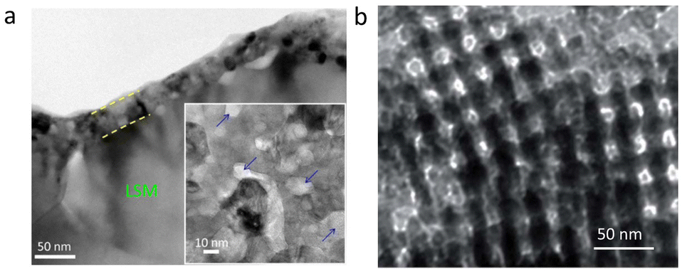 | ||
| Fig. 29 (a) Cross-sectional TEM micrograph of the porous ZrO2 nanolayer (about 40 nm) on the LSM/YSZ backbone. The inset blue arrows indicate the random distribution of pores. Reproduced with permission from ref. 351. Copyright 2016, Springer Nature. (b) TEM image of the CGO mesoporous powder. Reproduced with permission from ref. 353. Copyright 2018, The Royal Society of Chemistry. | ||
Post-treatment under particular conditions can regenerate nano-size particles/layers/pores, resulting in enhanced cell performances. Su et al. reported an effective top-down strategy for construction of mesoporous BSCF through post treatment of BSCF in H2O2.356 Dissolved Ba2+ and Sr2+ ions were induced by the reaction with H2O2, forming mesoporous BSCF. Its specific surface area was increased by about 60 times, and the ORR activity was significantly enhanced, yielding an excellent PPD of about 1800 mW cm−2 at 800 °C. Yu et al. employed more chemical solutions, including HCl, HNO3, NaOH, and H2O2, and implemented reactivation of the electrodes, resulting in a remarkable improvement in the reduction of ASRs of the electrode.357 Chrzan et al. deposited a mesoporous interlayer between the electrolyte and the electrode by spin coating for 120 seconds at 4000 rpm, and increased the active area for oxygen reduction and charge transfer across the interface.358 All these reports provided good concepts and alternative pathways for decorating a material surface, introducing nano effects, and consequently enhancing the cell electrochemical properties.
6. Summary and perspectives
CECs are all-solid energy conversion and storage devices that are built with high-temperature ionic conduction, endowing themselves with high efficiency, environmental-friendliness, economic affordability, etc., and are widely considered as the next-generation new energy technology. In this review, the fundamentals and operation modes of different types of CECs, including oxygen ion-conducting ceramic fuel/electrolysis cells, protonic ceramic fuel/electrolysis cells, etc. are first introduced. The main differences in the working mechanisms of these CECs are then discussed, with emphases on the ionic transformation, the electronic conduction, etc., which are extremely crucial for electrochemical reaction kinetics. Following these, the main challenges in CECs are addressed, such as a low level of ionic conduction of the electrolyte, inferior electrochemical activities of the electrodes, etc., especially at reduced temperature. Accordingly, it is claimed that reducing the operating temperature of CECs remains an pending issue though a great deal of record-breaking studies were reported over the last decade. NPs are activated groups with high-level specific surface areas, active sites, and so on. Multiple fantastic effects can be induced by the nanometre-size effect. For NPs-involved CECs, the electrochemical reactions including the ORR, HOR, OER and HER could be extensively boosted. Therefore, nanotechnologies enabling efficient synthesis of NPs and constructive fabrication of CECs with NPs are extremely critical for the fundamental research and development and commercialization of CECs. Accordingly, some favourable effects from nano-sized particles were identified, such as the advanced properties of ionic diffusion and electronic conduction in the lattice and along the interfaces. Then, the most-frequently used nanoengineering strategies in CECs were summarized and analysed, including typical physical and chemical methods. More importantly, recent advances in nanoengineering in electrolytes and electrodes were reviewed, in order to accurately track the latest development status of nanotechnologies in CECs. When scanning the development of nanotechnologies, infiltration and exsolution are the two most frequently applied approaches in the fabrication of nano-size particles. An infiltration method has been proved to be effective for in situ construction of NPs, but the fragile bonding interface between the coated NPs and substrate remains an unsolved issue. The latest cutting-edge solution to the preparation of active NPs is an in situ exsolution strategy. Attractive electrochemical activities can be derived from the strong phase attachment between the material matrix and NPs. The anchored NP co-catalysts affect internal ionic diffusion/electronic conduction behaviours, etc., and boost the electrochemical activities of electrodes in elevating adsorption to gas molecules, enhancing oxygen reduction, etc., depending on the size of the exsolved particles. Post-treatment processes were commonly used. Through appropriate chemical composition design, such as creating an A-site deficiency, subjecting to reducing atmospheres, etc., the exsolution reaction can be facilely triggered out, which provides tremendous opportunities for greatly broadening the catalyst family categories.Further development of next-generation CECs calls for nanotechnologies in the current stage. The electrolyte materials are still limited by inferior ionic conductivities at low temperature and cost-effective densification of electrolyte membranes. First, NPs were proved to be effective in enhancement of the sinterability of electrolyte particles due to the high-level specific surface areas that is helpful for the densification of electrolyte membranes. Moreover, the nano-sized ultrafine particles make the preparation of a nano-scale electrolyte membrane feasible. Meanwhile, a fuel electrode still suffers from the deficient activated sites for electrochemical reactions and high energy for sufficient activation as catalytic particles. The electrochemical properties of fuel electrodes are able to be elevated via nanotechnologies, especially for the nanocatalysts prepared through the in situ synthesis methods. The derived NPs can increase the active sites for the improvement of gas adsorption, optimize the ionic diffusion channels for mass transport and exchange, etc. In addition, through an exsolution strategy, the parent materials may be further modified, for example, the generation of oxygen vacancies once metal ions are exsolved out of the bulk lattice. Ni-based cermets remain the most popular candidates as the fuel electrodes of CECs. In contrast, most Ni-free fuel electrodes are limited by inferior catalytic activities, such as the low electronic conduction of perovskite-type fuel electrodes. Air electrodes are still confronted with challenges such as low catalytic activities at reduced temperatures and inferior thermal-mechanical matching with electrolytes, as well as poor chemical stabilities against harsh atmospheres. NPs with overwhelming surficial active sites and a nano-scale volume can improve the air electrode properties through boosting the adsorption to oxygen gas, lowering the activation energy of the catalysts, enhancing the mass transformation, and so on. Consequently, high cell performances with the modified electrolyte and electrode materials are reasonably to be expected.
Though a great number of achievements have been made through nanotechnologies in the last decade, many key challenges are still not completely solved in CECs. Therefore, some important targeted objectives in the research of nanotechnologies should be definitely addressed. The working mechanisms of NPs and bulk grains, the lack of approaches toward controllable fabrication of NPs, confined technical methods for accurate determination of the chemical composition of NPs obtained via a self-reconstruction pathway, the long-term durability of NPs, the scarcity of construction strategies toward nano-size interlayers and pores, etc. are valuable research topics in the research of NPs in CECs that call for in-depth investigations.
An accurate understanding of the growth mechanism and working principles of NPs in CECs is still pending, far from being experimentally identified. As for the in situ exsolved NPs, the ionic transport and electronic conduction between the anchored NPs and parent materials are still under debate. Indeed, the cell performances are proved to be enhanced while surficial NPs are formed. Even so, an in-depth reason for the enhanced performances should be figured out experimentally, at least at the level of accurate determination of ionic diffusion and electronic conduction that correlated with the derived NPs. As for the impregnated NPs, the working mechanisms may be much different from those of the NPs obtained by the exsolution method, which should cause more concerns in the future. Moreover, as listed in the tables, a concern remains on the faradaic efficiencies reported in previous literatures. They are more critical for accurately determining the reaction efficiencies, while current density is commonly influenced by side reactions offering incomplete information.359 It was found that most authors assumed ∼100% faradaic efficiencies in their work. However, according to a research result from Prof. Haile’ group, the real faradaic efficiencies were measured to be much lower than 80% below 1.6 V between 500 and 600 °C, which are extremely lower than those of the most reported data.360
Controllable fabrication of NPs is another important issue that should be addressed, which is beneficial for understanding in-depth the intrinsic catalysis processes of NPs and further improving the whole performances of CECs. Controllable synthesis of NPs includes three aspects at least: accurate synthesis of NPs with a particular chemical composition, construction of NPs with a specific size, and assembly of NPs with a unique morphology. Current technologies just remain under the status of the successful preparation of NPs, rather than tailoring their chemical compositions, their dimensions, and morphologies. These are challenging technical issues. Advanced technologies for controllable fabrication of NPs should be developed in the future. As for catalytic properties, the achievement of self-reconstruction of ultrasmall particles is definitely theoretically feasible. However, in CECs that are high-temperature equipment, is it accessible to minimize the exsolved NPs into the cluster scale or even reduce them into single-site metals as active sites is a question. Fortunately, some pioneering works have been reported. For instance, Zhou et al. successfully fabricated a Pd NP-anchored La0.5Sr0.5FeO3−δ–Ce0.8Sm0.2O2−δ electrode for CO2 electrolysis in an OCEC.361 Electrochemical and DFT calculation results implied that the Pd species were atomically anchored on the La0.5Sr0.5FeO3−δ phase. However, more references and multiple advanced technologies should be provided to give a full-scale description of single-atom catalysts of CECs in the future.
Inaccurate chemical composition of NPs hampers the action or progress of evaluating valuable information on NPs, making the controllable and orientated syntheses of NPs even more difficult. Although one-pot synthesis methods have been widely employed in the in situ fabrication of NPs, accurate determination of the chemical composition of NPs remains a challenging target till now. Therefore, the development of NPs in CECs calls for multidimensional theoretical knowledge and experimental technologies. For instance, the original chemical composition of active NPs should be determined by sophisticated measurements, rather than solely employing energy dispersive X-ray spectroscopy, as is widely employed in the current stage. To date, most technologies used in the syntheses of NPs display limited controllability over the chemical composition of NPs. New technologies in fabrication of NPs, such as, 3D-printing are worth trying.362,363 Herein, we strongly hold our viewpoint that accurate determination of the chemical composition is the prerequisite for controllable synthesis of NPs. Meanwhile, after the exsolution reaction, the chemical composition of the material matrix must be different, and the effects of the composition variation on the catalytic properties of the material matrix are worth readdressing. Coherent effects may be generated benefitting from the composition evolution in parent compounds, together with the derived NPs. Anyway, the key mechanism of the variation of the catalytic properties should be addressed, which deserves special attention.
Long-term operational stability of NPs is another important issue in CECs that has not been completely resolved. As far as we know, under some conditions, the electrode catalytic activities are boosted at the expense of their sustainability. In NPs, more activated surfaces are exposed to harsh atmospheres, which may in turn reduce their long-term stability. The trend in adherence to gaseous molecules, the dissociation of intermediate chemical species, etc., may drive the surficial active lattice ions to deviate their regular lattice sites, destroy the surficial symmetrical structure, and accelerate the formation of secondary phases. Then the catalysts with active NPs would suffer from more challenges in maintaining ultralong-term sustainability. More reliable data should be gathered for long-operation CECs, for example, thousands of hours cell sustainability measurement. In addition, long-term cycling tests are still necessary in order to accurately check the real endurance ability of nano-based CECs. Moreover, theoretical determination of the degeneration mechanisms of CECs while NPs are present is an interesting issue.
Apart from NPs, other nanostructures such as nanolayers, nanopores, etc. should be further optimized. The nano-size interlayers between the electrolytes and electrodes, nano-scale functional layers over catalyst surfaces, are effective for both the improvement of the energy conversion and storage abilities of CECs. More in-depth works are desirable to conduct toward accurate fabrication of nano-scale layers. Nanopores inside catalyst scaffolds are also effective for improving cell performances by optimizing the mass transport inside and enhancing the electrochemical reaction kinetics. However, there is still a lack in the study of the effects of nanopores on the electrochemical activities of NPs in CECs. In addition, more effective approaches for building nanopores in CECs should be developed. Conventional strategies, such as a template strategy, may provide well-dispersed nanopores in NPs, but may display low capability in realizing strong adherence between the electrolyte and electrode layers. New nanotechnologies are supposed to be produced. Kayaalp et al. successfully fabricated mesoporous La0.3Sr0.7Ti1−xFexO3±δ with a specific surface area of 65 m2 g−1 and an average pore size of 15 nm, through a novel template-free polymer complex approach.364 This work may inspire more ideas for the development of nanotechnologies. On the way toward practical application of CEC products, nano-size interlayers and nanopores may play critical roles in the future. Anyway, nanotechnologies have provided alternative strategies and new opportunities for further improvements of CECs in the last decade. We hope that this review would arouse much interest in nanotechnologies in the research of CECs. We also hope that this work could contribute some useful insights into the frontier research fields related to CECs, and inspire new actions toward the commercialization of CECs.
Author contributions
Z. Shao and J. Cao contributed to the central idea and conducted detailed analyses. J. Cao and Y. Ji collected the related resources. All authors contributed to the writing, editing and revising of the document.Conflicts of interest
There are no conflicts to declare.Acknowledgements
This work was financially supported by the Scientific Research Foundation of Education Department of Anhui Province of China (No. KJ2021ZD0043), the University Synergy Innovation Program of Anhui Province of China (No. GXXT-2022-010), the Australian Research Council Discovery Projects (DP200103315, DP200103332, DP230100685), and the Natural Science Foundation of Anhui Province of China (No. 2108085MB35).References
- L. Cozzi and T. Gould, World energy outlook, International Energy Agency, Paris, 2022 Search PubMed.
- S. Bilgen, Renewable Sustainable Energy Rev., 2014, 38, 890–902 CrossRef CAS.
- Z. Wu, P. Zhu, J. Yao, S. Zhang, J. Ren, F. Yang and Z. Zhang, Appl. Energy, 2020, 279, 115794 CrossRef CAS.
- S. Y. Gómez and D. Hotza, Renewable Sustainable Energy Rev., 2016, 61, 155–174 CrossRef.
- Y. Yi, A. D. Rao, J. Brouwer and G. S. Samuelsen, Nature, 2005, 144, 67–76 CAS.
- V. Saarinen, J. Pennanen, M. Kotisaari, O. Thomann, O. Himanen, S. D. Iorio, P. Hanoux, J. Aicart, K. Couturier, X. Sun, M. Chen and B. R. Sudireddy, Fuel Cells, 2021, 21, 477–487 CrossRef CAS.
- D. Yu, J. Hu, W. Wang and B. Gu, Fuel, 2023, 333, 126442 CrossRef CAS.
- M. Green, E. Dunlop, J. Hohl-Ebinger, M. Yoshita, N. Kopidakis and X. Hao, Prog. Photovoltaics, 2020, 29, 3–15 Search PubMed.
- S. Mekhilef, R. Saidur and A. Safari, Renewable Sustainable Energy Rev., 2012, 16, 981–989 CrossRef CAS.
- J. Guo, Y. Zheng, Z. Hu, C. Zheng, J. Mao, K. Du, M. Jaroniec, S.-Z. Qiao and T. Ling, Nat. Energy, 2023, 8, 264–272 CAS.
- J. Jia, L. C. Seitz, J. D. Benck, Y. Huo, Y. Chen, J. W. Ng, T. Bilir, J. S. Harris and T. F. Jaramillo, Nat. Commun., 2016, 7, 13237 CrossRef CAS PubMed.
- R. Bontempo and M. Manna, Energy Convers. Manage., 2019, 195, 1255–1279 CrossRef.
- H. Mohammed, A. Al-Othman, P. Nancarrow, M. Tawalbeh and M. El Haj Assad, Energy, 2019, 172, 207–219 CrossRef CAS.
- C. Duan, R. Kee, H. Zhu, N. Sullivan, L. Zhu, L. Bian, D. Jennings and R. O’Hayre, Nat. Energy, 2019, 4, 230–240 CrossRef CAS.
- R. Daneshpour and M. Mehrpooya, Energy Convers. Manage., 2018, 176, 274–286 CrossRef CAS.
- L. Zhang, H. Xie, Q. Niu, F. Wang, C. Xie and G. Wang, Sustainable Energy Fuels, 2023, 7, 1433–1446 RSC.
- A. Farsi and M. A. Rosen, Appl. Energy, 2023, 329, 120280 CrossRef CAS.
- C. Duan, J. Tong, M. Shang, S. Nikodemski, M. Sanders, S. Ricote, A. Almansoori and R. O’Hayre, Science, 2015, 349, 1321–1326 CrossRef CAS PubMed.
- J. Cao, C. Su, Y. Ji, G. Yang and Z. Shao, J. Energy Chem., 2020, 57, 406–427 CrossRef.
- M. Han, X. Tang, H. Yin and S. Peng, J. Power Sources, 2007, 165, 757–763 CrossRef CAS.
- J. Vanherle, T. Horita, T. Kawada, N. Sakai, H. Yokokawa and M. Dokiya, Solid State Ionics, 1996, 86–88, 1255–1258 CrossRef CAS.
- C. Zuo, S. Zha, M. Liu, M. Hatano and M. Uchiyama, Adv. Mater., 2006, 18, 3318–3320 CrossRef CAS.
- L. Yang, S. Wang, K. Blinn, M. Liu, Z. Liu, Z. Cheng and M. Liu, Science, 2009, 326, 126–130 CrossRef CAS PubMed.
- K. D. Kreuer, S. Adams, W. Münch, A. Fuchs, U. Klock and J. Maier, Solid State Ionics, 2001, 145, 295–306 CrossRef CAS.
- Z. Shao and S. M. Haile, Nature, 2004, 255–258 Search PubMed.
- P. H. Anthony Petric and F. Tietz, Solid State Ionics, 2000, 135, 719–725 CrossRef.
- H. Ding, W. Wu, C. Jiang, Y. Ding, W. Bian, B. Hu, P. Singh, C. J. Orme, L. Wang, Y. Zhang and D. Ding, Nat. Commun., 2020, 11, 1907 CrossRef CAS PubMed.
- B. Zhao, L. Zhang, D. Zhen, S. Yoo, Y. Ding, D. Chen, Y. Chen, Q. Zhang, B. Doyle, X. Xiong and M. Liu, Nat. Commun., 2017, 8, 14586 CrossRef CAS PubMed.
- S. Choi, S. Yoo, J.-Y. Shin and G. Kim, J. Electrochem. Soc., 2011, 158, B995 CrossRef CAS.
- M. Saqib, I.-G. Choi, H. Bae, K. Park, J.-S. Shin, Y.-D. Kim, J.-I. Lee, M. Jo, Y.-C. Kim, K.-S. Lee, S.-J. Song, E. D. Wachsman and J.-Y. Park, Energy Environ. Sci., 2021, 14, 2472–2484 RSC.
- Y. Song, Y. Chen, M. Xu, W. Wang, Y. Zhang, G. Yang, R. Ran, W. Zhou and Z. Shao, Adv. Mater., 2020, 32, 1906979 CrossRef CAS PubMed.
- K. Pei, Y. Zhou, K. Xu, H. Zhang, Y. Ding, B. Zhao, W. Yuan, K. Sasaki, Y. Choi, Y. Chen and M. Liu, Nat. Commun., 2022, 13, 2207 CrossRef CAS PubMed.
- R. Perry,Report on the status of the solid oxide fuel cell program, United States Department of Energy, Washington, DC, 2019 Search PubMed.
- Technical Targets for High Temperature Electrolysis, https://www.energy.gov/eere/fuelcells/technical-targets-high-temperature-electrolysis, accessed 2023.
- M. Li, M. Zhao, F. Li, W. Zhou, V. K. Peterson, X. Xu, Z. Shao, I. Gentle and Z. Zhu, Nat. Commun., 2017, 8, 13990 CrossRef CAS PubMed.
- Z. Wang, Y. Wang, J. Wang, Y. Song, M. J. Robson, A. Seong, M. Yang, Z. Zhang, A. Belotti, J. Liu, G. Kim, J. Lim, Z. Shao and F. Ciucci, Nat. Catal., 2022, 5, 777–787 CrossRef CAS.
- P. Mojaver, A. Chitsaz, M. Sadeghi and S. Khalilarya, Energy Convers. Manage., 2020, 205, 112455 CrossRef CAS.
- I.-H. Kim, D.-K. Lim, H. Bae, A. Bhardwaj, J.-Y. Park and S.-J. Song, J. Mater. Chem. A, 2019, 7, 21321–21328 RSC.
- Y. Zhang, R. Knibbe, J. Sunarso, Y. Zhong, W. Zhou, Z. Shao and Z. Zhu, Adv. Mater., 2017, 29, 1700132 CrossRef PubMed.
- J. Cao, Y. Li, Y. Zheng, S. Wang, W. Zhang, X. Qin, G. Geng and B. Yu, Adv. Energy Mater., 2022, 12, 2200899 CrossRef CAS.
- F. He, Y. Zhou, T. Hu, Y. Xu, M. Hou, F. Zhu, D. Liu, H. Zhang, K. Xu, M. Liu and Y. Chen, Adv. Mater., 2023, 2209469 CrossRef CAS PubMed.
- C. K. Lim, Q. Liu, J. Zhou, Q. Sun and S. H. Chan, J. Power Sources, 2017, 342, 79–87 CrossRef CAS.
- H. Malerød-Fjeld, D. Clark, I. Yuste-Tirados, R. Zanón, D. Catalán-Martinez, D. Beeaff, S. H. Morejudo, P. K. Vestre, T. Norby, R. Haugsrud, J. M. Serra and C. Kjølseth, Nat. Energy, 2017, 2, 923–931 CrossRef.
- A. Hauch, K. Brodersen, M. Chen and M. B. Mogensen, Solid State Ionics, 2016, 293, 27–36 CrossRef CAS.
- F. Monaco, M. Hubert, J. Vulliet, J. P. Ouweltjes, D. Montinaro, P. Cloetens, P. Piccardo, F. Lefebvre-Joud and J. Laurencin, J. Electrochem. Soc., 2019, 166, F1229–F1242 CrossRef CAS.
- S. Harboe, A. Schreiber, N. Margaritis, L. Blum, O. Guillon and N. H. Menzler, Int. J. Hydrogen Energy, 2020, 45, 8015–8030 CrossRef CAS.
- N. H. Menzler, D. Sebold, Y. J. Sohn and S. Zischke, J. Power Sources, 2020, 478, 228770 CrossRef CAS.
- C. Duan, R. J. Kee, H. Zhu, C. Karakaya, Y. Chen, S. Ricote, A. Jarry, E. J. Crumlin, D. Hook, R. Braun, N. P. Sullivan and R. O'Hayre, Nature, 2018, 557, 217–222 CrossRef CAS PubMed.
- M. A. Azizi and J. Brouwer, Appl. Energy, 2018, 215, 237–289 CrossRef CAS.
- R. J. Braun, A. Dubois, K. Ferguson, C. Duan, C. Karakaya, R. J. Kee, H. Zhu, N. P. Sullivan, E. Tang, M. Pastula, A. Wood, T. Joia and R. O'Hayre, ECS Trans., 2019, 91, 997–1008 CrossRef CAS.
- W. Zhang, X. Hu, Y. Zhou, Z. Luo, G. Nam, Y. Ding, T. Li, Z. Liu, Y. Ahn, N. Kane, W. Wang, J. Hou, D. Spradling and M. Liu, Adv. Energy Mater., 2022, 12, 2202928 CrossRef CAS.
- C. Wei, Z. Liu, C. Li, S. Singh, H. Lu, Y. Gong, P. Li, H. Wang, X. Yang, M. Xu and S. Mu, Int. J. Coal Sci. Technol., 2021, 8, 401–411 CrossRef CAS.
- W. Bian, W. Wu, B. Wang, W. Tang, M. Zhou, C. Jin, H. Ding, W. Fan, Y. Dong, J. Li and D. Ding, Nature, 2022, 604, 479–485 CrossRef CAS PubMed.
- N. Nasani, D. Ramasamy, S. Mikhalev, A. V. Kovalevsky and D. P. Fagg, J. Power Sources, 2015, 278, 582–589 CrossRef CAS.
- S. A. Chizhik, I. V. Kovalev, M. P. Popov, S. F. Bychkov and A. P. Nemudry, Chem. Eng. J., 2022, 445, 136724 CrossRef CAS.
- M. Papac, V. Stevanovic, A. Zakutayev and R. O'Hayre, Nat. Mater., 2021, 20, 301–313 CrossRef CAS PubMed.
- J. H. Swisher, L. Jibril, S. H. Petrosko and C. A. Mirkin, Nat. Rev. Mater., 2022, 7, 428–448 CrossRef CAS.
- E. D. Wachsman and K. T. Lee, Science, 2011, 334, 935–939 CrossRef CAS PubMed.
- J. C. Njodzefon, D. Klotz, A. Kromp, A. Weber and E. Ivers-Tiffée, J. Electrochem. Soc., 2013, 160, F313–F323 CrossRef CAS.
- M. Trini, A. Hauch, S. De Angelis, X. Tong, P. V. Hendriksen and M. Chen, J. Power Sources, 2020, 450, 227599 CrossRef CAS.
- F. Dong, D. Chen, Y. Chen, Q. Zhao and Z. Shao, J. Mater. Chem., 2012, 22, 15071–15079 RSC.
- R. L. Cook and A. F. Sammells, Solid State Ionics, 1991, 45, 311–321 CrossRef CAS.
- J. Cao, C. Su, Y. Ji, G. Yang and Z. Shao, J. Energy Chem., 2021, 57, 406–427 CrossRef CAS.
- C. Yamagata, D. R. Leme and S. R. H. M. Castanho, J. Eur. Ceram. Soc., 2019, 39, 3416–3420 CrossRef CAS.
- R. Haider, Y. Wen, Z. F. Ma, D. P. Wilkinson, L. Zhang, X. Yuan, S. Song and J. Zhang, Chem. Soc. Rev., 2021, 50, 1138–1187 RSC.
- K. Jiao, J. Xuan, Q. Du, Z. Bao, B. Xie, B. Wang, Y. Zhao, L. Fan, H. Wang, Z. Hou, S. Huo, N. P. Brandon, Y. Yin and M. D. Guiver, Nature, 2021, 595, 361–369 CrossRef CAS PubMed.
- S. Stiber, H. Balzer, A. Wierhake, F. J. Wirkert, J. Roth, U. Rost, M. Brodmann, J. K. Lee, A. Bazylak, W. Waiblinger, A. S. Gago and K. A. Friedrich, Adv. Energy Mater., 2021, 11, 2100630 CrossRef CAS.
- D. J. Brett, A. Atkinson, N. P. Brandon and S. J. Skinner, Chem. Soc. Rev., 2008, 37, 1568–1578 RSC.
- J. Ding, J. Balachandran, X. Sang, W. Guo, J. S. Anchell, G. M. Veith, C. A. Bridges, Y. Cheng, C. M. Rouleau, J. D. Poplawsky, N. Bassiri-Gharb, R. R. Unocic and P. Ganesh, Chem. Mater., 2018, 30, 4919–4925 CrossRef CAS.
- J. Maier, Solid State Ionics, 2000, 131, 13–22 CrossRef CAS.
- V. S. Drozd, N. A. Zybina, K. E. Abramova, M. Y. Parfenov, U. Kumar, H. Valdés, P. G. Smirniotis and A. V. Vorontsov, Solid State Ionics, 2019, 339, 115009 CrossRef CAS.
- Y. Cao, M. J. Gadre, A. T. Ngo, S. B. Adler and D. D. Morgan, Nat. Commun., 2019, 10, 1346 CrossRef PubMed.
- D. Chen and Z. Shao, Int. J. Hydrogen Energy, 2011, 36, 6948–6956 CrossRef CAS.
- C. Endler-Schuck, J. Joos, C. Niedrig, A. Weber and E. Ivers-Tiffée, Solid State Ionics, 2015, 269, 67–79 CrossRef CAS.
- S. Saher, S. Naqash, B. A. Boukamp, B. Hu, C. Xia and H. J. M. Bouwmeester, J. Mater. Chem. A, 2017, 5, 4991–4999 RSC.
- J. Maier, Solid State Ionics, 2004, 175, 7–12 CrossRef CAS.
- A. Uthayakumar, A. Pandiyan and S. B. Krishna Moorthy, Int. J. Hydrogen Energy, 2018, 43, 23488–23499 CrossRef CAS.
- Y. Liu, Z. Shao, T. Mori and S. P. Jiang, Mater. Rep.: Energy, 2021, 1, 100003 CAS.
- B. Mo, J. Rix, U. Pal, S. Basu and S. Gopalan, J. Electrochem. Soc., 2020, 167, 134506 CrossRef CAS.
- N. Mushtaq, Y. Lu, C. Xia, W. Dong, B. Wang, M. A. K. Y. Shah, S. Rauf, M. Akbar, E. Hu, R. Raza, M. I. Asghar, P. D. Lund and B. Zhu, Appl. Catal., B, 2021, 298, 120503 CrossRef CAS.
- M. A. K. Y. Shah, S. Rauf, N. Mushtaq, B. Zhu, Z. Tayyab, M. Yousaf, M. B. Hanif, P. D. Lund, Y. Lu and M. I. Asghar, ACS Appl. Energy Mater., 2021, 4, 5798–5808 CrossRef CAS.
- X. Wang, Y. Ma, S. Li, B. Zhu and M. Muhammed, Int. J. Hydrogen Energy, 2012, 37, 19380–19387 CrossRef CAS.
- L. Fan, C. Wang, M. Chen, J. Di, J. Zheng and B. Zhu, Int. J. Hydrogen Energy, 2011, 36, 9987–9993 CrossRef CAS.
- C. Xia, Y. Li, Y. Tian, Q. Liu, Z. Wang, L. Jia, Y. Zhao and Y. Li, J. Power Sources, 2010, 195, 3149–3154 CrossRef CAS.
- M. Khoshkalam, D. Tripković, X. Tong, M. A. Faghihi-Sani, M. Chen and P. V. Hendriksen, J. Power Sources, 2020, 457, 228035 CrossRef CAS.
- J. Hong, A. Bhardwaj, Y. Namgung, H. Bae and S.-J. Song, J. Mater. Chem. A, 2020, 8, 23473–23487 RSC.
- Y. Zhang, F. Yan, M. Yan, Y. Wan, Z. Jiao, C. Xia, F. Chen and M. Ni, J. Power Sources, 2019, 427, 112–119 CrossRef CAS.
- Y. Zhang, B. Chen, D. Guan, M. Xu, R. Ran, M. Ni, W. Zhou, R. O'Hayre and Z. Shao, Nature, 2021, 591, 246–251 CrossRef CAS PubMed.
- S. Wang, X. Hao and W. Zhan, Int. J. Hydrogen Energy, 2017, 42, 29881–29887 CrossRef CAS.
- C. Graves, S. D. Ebbesen, S. H. Jensen, S. B. Simonsen and M. B. Mogensen, Nat. Mater., 2015, 14, 239–244 CrossRef CAS PubMed.
- X. Tong, P. V. Hendriksen, A. Hauch, X. Sun and M. Chen, J. Electrochem. Soc., 2020, 167, 024519 CrossRef CAS.
- H. T. Phan and A. J. Haes, J. Phys. Chem. C, 2019, 123, 16495–16507 CrossRef CAS PubMed.
- A. Bertei, E. Ruiz-Trejo, K. Kareh, V. Yufit, X. Wang, F. Tariq and N. P. Brandon, Nano Energy, 2017, 38, 526–536 CrossRef CAS.
- D. Han, X. Liu, T. S. Bjørheim and T. Uda, Adv. Energy Mater., 2021, 11, 2003149 CrossRef CAS.
- M. Choi, J. Paik, D. Kim, D. Woo, J. Lee, S. J. Kim, J. Lee and W. Lee, Energy Environ. Sci., 2021, 14, 6476–6483 RSC.
- H. An, H.-W. Lee, B.-K. Kim, J.-W. Son, K. J. Yoon, H. Kim, D. Shin, H.-I. Ji and J.-H. Lee, Nat. Energy, 2018, 3, 870–875 CrossRef CAS.
- D. Konwar, N. T. Q. Nguyen and H. H. Yoon, Int. J. Hydrogen Energy, 2015, 40, 11651–11658 CrossRef CAS.
- L. Zhang, F. Liu, K. Brinkman, K. L. Reifsnider and A. V. Virkar, J. Power Sources, 2014, 247, 947–960 CrossRef CAS.
- J.-H. Wan, J. Q. Yan and J. B. Goodenough, J. Electrochem. Soc., 2005, 152, A1511 CrossRef CAS.
- X. Xu, L. Bi and X. S. Zhao, J. Membr. Sci., 2018, 558, 17–25 CrossRef CAS.
- F. Bozza, K. Bator, W. W. Kubiak and T. Graule, J. Eur. Ceram. Soc., 2016, 36, 101–107 CrossRef CAS.
- S. Hossain, A. M. Abdalla, N. Radenahmad, A. K. M. Zakaria, J. H. Zaini, S. M. H. Rahman, S. G. Eriksson, J. T. S. Irvine and A. K. Azad, Int. J. Hydrogen Energy, 2018, 43, 894–907 CrossRef CAS.
- D. Ciria, M. Ben Hassine, M. Jiménez-Melendo, A. Iakovleva, P. Haghi-Ashtiani, V. Aubin and G. Dezanneau, J. Power Sources, 2016, 321, 226–232 CrossRef CAS.
- Z. Khakpour, A. A. Youzbashi, A. Maghsoudipour and K. Ahmadi, Powder Technol., 2011, 214, 117–121 CrossRef CAS.
- M. Ghasdi and H. Alamdari, Sens. Actuators, B, 2010, 148, 478–485 CrossRef CAS.
- N. Bhardwaj and S. C. Kundu, Biotechnol. Adv., 2010, 28, 325–347 CrossRef CAS PubMed.
- J. Bai, Z. Han, B. Lv, X. Chen, X. Zhu and D. Zhou, Int. J. Hydrogen Energy, 2021, 46, 8132–8142 CrossRef CAS.
- L. Sun, G. Yuan, L. Gao, J. Yang, M. Chhowalla, M. H. Gharahcheshmeh, K. K. Gleason, Y. S. Choi, B. H. Hong and Z. Liu, Nat. Rev. Methods Primers, 2021, 1, 5 CrossRef CAS.
- R. W. Johnson, A. Hultqvist and S. F. Bent, Mater. Today, 2014, 17, 236–246 CrossRef CAS.
- Y. Cheng, T.-S. Oh, R. Wilson, R. J. Gorte and J. M. Vohs, J. Electrochem. Soc., 2017, 164, F525–F529 CrossRef CAS.
- E.-K. Shin, E. Anggia, A. S. Parveen and J.-S. Park, Int. J. Hydrogen Energy, 2019, 44, 31323–31332 CrossRef CAS.
- K. Kousi, D. Neagu, L. Bekris, E. I. Papaioannou and I. S. Metcalfe, Angew. Chem., Int. Ed., 2020, 59, 2510–2519 CrossRef CAS PubMed.
- J. Hwang, Z. Feng, N. Charles, X. R. Wang, D. Lee, K. A. Stoerzinger, S. Muy, R. R. Rao, D. Lee, R. Jacobs, D. Morgan and Y. Shao-Horn, Mater. Today, 2019, 31, 100–118 CrossRef CAS.
- H. Han, J. Park, S. Y. Nam, K. J. Kim, G. M. Choi, S. S. P. Parkin, H. M. Jang and J. T. S. Irvine, Nat. Commun., 2019, 10, 1471 CrossRef PubMed.
- J. Pan, Y. Ye, M. Zhou, X. Sun and Y. Chen, Energy Fuels, 2022, 36, 12253–12260 CrossRef CAS.
- Y. Shen, T. Liu, R. Li, H. Lv, N. Ta, X. Zhang, Y. Song, Q. Liu, W. Feng, G. Wang and X. Bao, Natl. Sci. Rev., 2023, 10, nwad078 CrossRef PubMed.
- D. Jennings, S. Ricote, J. Santiso, J. Caicedo and I. Reimanis, Acta Mater., 2022, 228, 117752 CrossRef CAS.
- L. Rioja-Monllor, C. Bernuy-Lopez, M.-L. Fontaine, T. Grande and M.-A. Einarsrud, J. Mater. Chem. A, 2019, 7, 8609–8619 RSC.
- J.-I. Jung, M. Risch, S. Park, M. G. Kim, G. Nam, H.-Y. Jeong, Y. Shao-Horn and J. Cho, Energy Environ. Sci., 2016, 9, 176–183 RSC.
- M. A. Laguna-Bercero, A. R. Hanifi, L. Menand, N. K. Sandhu, N. E. Anderson, T. H. Etsell and P. Sarkar, Electrochim. Acta, 2018, 268, 195–201 CrossRef CAS.
- C. Yang, J. Li, J. Newkirk, V. Baish, R. Hu, Y. Chen and F. Chen, J. Mater. Chem. A, 2015, 3, 15913–15919 RSC.
- T. Wang, J. Wang, L. Yu, Z. Ye, X. Hu, G. E. Marnellos and D. Dong, J. Eur. Ceram. Soc., 2018, 38, 5051–5057 CrossRef CAS.
- A. Seong, J. Kim, J. Kim, S. Kim, S. Sengodan, J. Shin and G. Kim, J. Electrochem. Soc., 2018, 165, F1098–F1102 CrossRef CAS.
- Y.-C. Wang, W. Huang, L.-Y. Wan, J. Yang, R.-J. Xie, Y.-P. Zheng, Y.-Z. Tan, Y.-S. Wang, K. Zaghib, L.-R. Zheng, S.-H. Sun, Z.-Y. Zhou and S.-G. Sun, Sci. Adv., 2022, 8, eadd8873 CrossRef CAS PubMed.
- A. Avid and I. V. Zenyuk, Curr. Opin. Electrochem., 2021, 25, 100634 CrossRef CAS.
- K. Suzuki, S. Sato and M. Fujita, Nat. Chem., 2010, 2, 25–29 CrossRef CAS PubMed.
- F. Cheng, Z. Tao, J. Liang and J. Chen, Chem. Mater., 2008, 20, 667–681 CrossRef CAS.
- D. H. Prasad, J. W. Son, B. K. Kim, H. W. Lee and J. H. Lee, J. Eur. Ceram. Soc., 2008, 28, 3107–3112 CrossRef CAS.
- N. A. Baharuddin, A. Muchtar, M. R. Somalu, N. S. Kalib and N. F. Raduwan, Int. J. Hydrogen Energy, 2019, 44, 30682–30691 CrossRef CAS.
- S. Demirci, M. Yurddaskal, T. Dikici and C. Sarıoğlu, J. Hazard. Mater., 2018, 345, 27–37 CrossRef CAS PubMed.
- H. Zhou, L. Jiang, X. Chen, A. Wu, Z. Tang and H. Chen, J. Lumin., 2022, 245, 118774 CrossRef CAS.
- B. Niu, F. Zhang, H. Ping, N. Li, J. Zhou, L. Lei, J. Xie, J. Zhang, W. Wang and Z. Fu, Sci. Rep., 2017, 7, 3421 CrossRef PubMed.
- F. J. A. Loureiro, D. A. Macedo, R. M. Nascimento, M. R. Cesário, J. P. F. Grilo, A. A. Yaremchenko and D. P. Fagg, J. Eur. Ceram. Soc., 2019, 39, 1846–1853 CrossRef CAS.
- T. V. Gavrilović, D. J. Jovanović and M. D. Dramićanin, in Nanomaterials for Green Energy, ed. B. A. Bhanvase, V. B. Pawade, S. J. Dhoble, S. H. Sonawane and M. Ashokkumar, Elsevier, Amsterdam, 2018, ch. 2, pp. 55–81 Search PubMed.
- T. Klemensø and M. Mogensen, J. Am. Ceram. Soc., 2007, 90, 3582–3588 CrossRef.
- L. Zhu, C. Cadigan, C. Duan, J. Huang, L. Bian, L. Le, C. H. Hernandez, V. Avance, R. O'Hayre and N. P. Sullivan, Commun. Chem., 2021, 4, 121 CrossRef CAS PubMed.
- D. Kim, K. T. Bae, K. J. Kim, H.-N. Im, S. Jang, S. Oh, S. W. Lee, T. H. Shin and K. T. Lee, ACS Energy Lett., 2022, 7, 2393–2400 CrossRef CAS.
- Z. Gao, E. C. Miller and S. A. Barnett, Adv. Funct. Mater., 2014, 24, 5703–5709 CrossRef CAS.
- C. Zhu, S. Hou, L. Hou and K. Xie, Int. J. Hydrogen Energy, 2018, 43, 17040–17047 CrossRef CAS.
- Y. Wang, J. Xu, X. Meng, T. Liu and F. Chen, Electrochem. Commun., 2017, 79, 63–67 CrossRef CAS.
- J. Xu, S. Wan, Y. Wang, S. Huang, Z. Yuan, F. Chen, Y. Zhang and T. Liu, Int. J. Hydrogen Energy, 2021, 46, 10876–10891 CrossRef CAS.
- K. J. Kim, M. K. Rath, H. H. Kwak, H. J. Kim, J. W. Han, S.-T. Hong and K. T. Lee, ACS Catal., 2019, 9, 1172–1182 CrossRef CAS.
- Z. Zhao, J. Cui, M. Zou, S. Mu, H. Huang, Y. Meng, K. He, K. S. Brinkman and J. Tong, J. Power Sources, 2020, 450, 227609 CrossRef CAS.
- K. Pei, Y. Zhou, K. Xu, Z. He, Y. Chen, W. Zhang, S. Yoo, B. Zhao, W. Yuan, M. Liu and Y. Chen, Nano Energy, 2020, 72, 104704 CrossRef CAS.
- L. Bi, S. P. Shafi, E. H. Da'as and E. Traversa, Small, 2018, 14, 1801231 CrossRef PubMed.
- G. Li, H. Jin, Y. Cui, L. Gui, B. He and L. Zhao, J. Power Sources, 2017, 341, 192–198 CrossRef CAS.
- S. Lee, S. Park, S. Wee, H. W. Baek and D. Shin, Solid State Ionics, 2018, 320, 347–352 CrossRef CAS.
- J. S. Park, H. J. Choi, G. D. Han, J. Koo, E. H. Kang, D. H. Kim, K. Bae and J. H. Shim, J. Power Sources, 2021, 482, 229043 CrossRef CAS.
- H. J. Jeong, W. Chang, B. G. Seo, Y. S. Choi, K. H. Kim, D. H. Kim and J. H. Shim, Small, 2023, 19, 2208149 CrossRef CAS PubMed.
- J. Nielsen, Å. H. Persson, B. R. Sudireddy, J. T. S. Irvine and K. Thydén, J. Power Sources, 2017, 372, 99–106 CrossRef CAS.
- T. Wei, P. Qiu, J. Yang, L. Jia, B. Chi, J. Pu and J. Li, J. Power Sources, 2021, 484, 229199 CrossRef CAS.
- M. Liang, Y. Zhu, Y. Song, D. Guan, Z. Luo, G. Yang, S. P. Jiang, W. Zhou, R. Ran and Z. Shao, Adv. Mater., 2022, 34, e2106379 CrossRef PubMed.
- Y. Fan, X. Xi, D. Medvedev, Q. Wang, J. Li, J.-L. Luo and X.-Z. Fu, J. Power Sources, 2021, 515, 230634 CrossRef CAS.
- X. Zhou, Y. Lu, W. Yang, H. Hu, J. Li, X. Wang, S. Guo and X. Ding, Electrochim. Acta, 2023, 437, 141425 CrossRef CAS.
- J. H. Kim, J. Hong, D.-K. Lim, S. Ahn, J. Kim, J. K. Kim, D. Oh, S. Jeon, S.-J. Song and W. Jung, Energy Environ. Sci., 2022, 15, 1097–1105 RSC.
- M. Qin, Y. Xiao, H. Yang, T. Tan, Z. Wang, X. Fan and C. Yang, Appl. Catal., B, 2021, 299, 120613 CrossRef CAS.
- Z. Sun, W. Fan and Y. Bai, Adv. Sci., 2022, 9, e2200250 CrossRef PubMed.
- J. H. Kim, J. K. Kim, H. G. Seo, D. K. Lim, S. J. Jeong, J. Seo, J. Kim and W. Jung, Adv. Funct. Mater., 2020, 30, 2001326 CrossRef CAS.
- X. Chen, J. Wang, N. Yu, Y. Wang, D. Zhang, M. Ni, F. Chen, T. Liu and M. Ding, J. Membr. Sci., 2023, 677, 121637 CrossRef CAS.
- Y. Chen, S. Yoo, K. Pei, D. Chen, L. Zhang, B. deGlee, R. Murphy, B. Zhao, Y. Zhang, Y. Chen and M. Liu, Adv. Funct. Mater., 2017, 28, 1704907 CrossRef.
- I. T. Bello, N. Yu, Y. Song, J. Wang, T. S. Chan, S. Zhao, Z. Li, Y. Dai, J. Yu and M. Ni, Small, 2022, 18, e2203207 CrossRef PubMed.
- Q. Huang, S. Jiang, Y. Wang, J. Jiang, Y. Chen, J. Xu, H. Qiu, C. Su and D. Chen, Nano Res., 2023, 16, 9280–9288 CrossRef CAS.
- S. Ryu, J. Hwang, W. Jeong, W. Yu, S. Lee, K. Kim, C. Zheng, Y. H. Lee and S. W. Cha, ACS Appl. Mater. Interfaces, 2023, 15, 11845–11852 CrossRef CAS PubMed.
- Y. Liu, J. Shuang, X. Tong, S. Yang, Y. Yang and M. Wei, Electrochim. Acta, 2019, 298, 852–857 CrossRef CAS.
- Z. Zhao, X. Wang, S. Tang, M. Cheng and Z. Shao, Int. J. Hydrogen Energy, 2021, 46, 25332–25340 CrossRef CAS.
- Z. Wang, Y. Wang, N. Li, Y. Tong, Y. Teng, D. Wang, C. Chen and Z. Zhan, Int. J. Hydrogen Energy, 2023, 48, 12949–12957 CrossRef CAS.
- C. Cui, Y. Wang, Y. Tong, S. Wang, C. Chen and Z. Zhan, Int. J. Hydrogen Energy, 2021, 46, 20305–20312 CrossRef CAS.
- M. Zheng, S. Wang, Y. Yang and C. Xia, J. Mater. Chem. A, 2018, 6, 2721–2729 RSC.
- H. Lv, Y. Zhou, X. Zhang, Y. Song, Q. Liu, G. Wang and X. Bao, J. Energy Chem., 2019, 35, 71–78 CrossRef.
- B. Zhang, S. Zhang, Z. Zhang, K. Tang and C. Xia, J. Power Sources, 2023, 556, 232467 CrossRef CAS.
- X. Zhang, Y. Song, F. Guan, Y. Zhou, H. Lv, G. Wang and X. Bao, J. Catal., 2018, 359, 8–16 CrossRef CAS.
- S. Lee, S. H. Woo, T. H. Shin and J. T. S. Irvine, Chem. Eng. J., 2021, 420, 127706 CrossRef CAS.
- X. Tong, S. Ovtar, K. Brodersen, P. V. Hendriksen and M. Chen, ACS Appl. Mater. Interfaces, 2019, 11, 25996–26004 CrossRef CAS PubMed.
- M. Li, J. Hou, Y. Fan, X. Xi, X.-Z. Fu and J.-L. Luo, Electrochim. Acta, 2022, 426, 140771 CrossRef CAS.
- X. Zhang, L. Ye and K. Xie, Energy Fuels, 2022, 36, 11576–11583 CrossRef CAS.
- H. Lv, L. Lin, X. Zhang, R. Li, Y. Song, H. Matsumoto, N. Ta, C. Zeng, Q. Fu, G. Wang and X. Bao, Nat. Commun., 2021, 12, 5665 CrossRef CAS PubMed.
- T. Liu, H. Liu, X. Zhang, L. Lei, Y. Zhang, Z. Yuan, F. Chen and Y. Wang, J. Mater. Chem. A, 2019, 7, 13550–13558 RSC.
- J. Zhou, J. Yang, Z. Zong, L. Fu, Z. Lian, C. Ni, J. Wang, Y. Wan and K. Wu, J. Power Sources, 2020, 468, 228349 CrossRef CAS.
- L. Zou, Y. Tian, J. Pu and B. Chi, J. Alloys Compd., 2022, 900, 163540 CrossRef CAS.
- Y. Tan, A. Wang, L. Jia, D. Yan, B. Chi, J. Pu and J. Li, Int. J. Hydrogen Energy, 2017, 42, 4456–4464 CrossRef CAS.
- Y. Zhou, W. Zhang, N. Kane, Z. Luo, K. Pei, K. Sasaki, Y. Choi, Y. Chen, D. Ding and M. Liu, Adv. Funct. Mater., 2021, 31, 2105386 CrossRef CAS.
- L. Fu, J. Zhou, J. Yang, Z. Lian, J. Wang, Y. Cheng and K. Wu, Appl. Surf. Sci., 2020, 511, 145525 CrossRef CAS.
- Y. Liu, Y. Tian, Y. Wang, Y. Li, J. Pu, F. Ciucci and B. Chi, Electrochim. Acta, 2022, 430, 141032 CrossRef CAS.
- N. Duan, M. Gao, B. Hua, M. Li, B. Chi, J. Li and J.-L. Luo, J. Mater. Chem. A, 2020, 8, 3988–3998 RSC.
- Z. Tan, J. T. Song, A. Takagaki and T. Ishihara, J. Mater. Chem. A, 2021, 9, 1530–1540 RSC.
- P. Wu, Y. Tian, Z. Lü, X. Zhang and L. Ding, Int. J. Hydrogen Energy, 2022, 47, 747–760 CrossRef CAS.
- A. Orera, A. Betato, J. Silva-Treviño, Á. Larrea and M. Á. Laguna-Bercero, J. Mater. Chem. A, 2022, 10, 2541–2549 RSC.
- M. Liang, Y. Wang, Y. Song, D. Guan, J. Wu, P. Chen, A. Maradesa, M. Xu, G. Yang, W. Zhou, W. Wang, R. Ran, F. Ciucci and Z. Shao, Appl. Catal., B, 2023, 331, 122682 CrossRef CAS.
- Z. Chen, L. Jiang, S. He, C. Guan, Y. Zou, Z. Yue, N. Ai, S. P. Jiang, Y. Shao and K. Chen, Appl. Catal., B, 2022, 305, 121056 CrossRef CAS.
- Y. Tan, S. Gao, C. Xiong and B. Chi, Int. J. Hydrogen Energy, 2020, 45, 19823–19830 CrossRef CAS.
- J. Hui, D. Neagu, D. N. Miller, X. Yue, C. Ni and J. T. S. Irvine, Solid State Ionics, 2018, 315, 126–130 CrossRef CAS.
- J.-h Myung, D. Neagu, D. N. Miller and J. T. S. Irvine, Nature, 2016, 537, 528–531 CrossRef CAS PubMed.
- Y. Sun, J. Li, Y. Zeng, B. S. Amirkhiz, M. Wang, Y. Behnamian and J. Luo, J. Mater. Chem. A, 2015, 3, 11048–11056 RSC.
- M. Bahout, P. B. Managutti, V. Dorcet, A. Le Gal La Salle, S. Paofai and T. C. Hansen, J. Mater. Chem. A, 2020, 8, 3590–3597 RSC.
- D. Neagu, T. S. Oh, D. N. Miller, H. Menard, S. M. Bukhari, S. R. Gamble, R. J. Gorte, J. M. Vohs and J. T. S. Irvine, Nat. Commun., 2015, 6, 8120 CrossRef PubMed.
- P. B. Managutti, S. Tymen, X. Liu, O. Hernandez, C. Prestipino, A. Le Gal La Salle, S. Paul, L. Jalowiecki-Duhamel, V. Dorcet, A. Billard, P. Briois and M. Bahout, ACS Appl. Mater. Interfaces, 2021, 13, 35719–35728 CrossRef CAS PubMed.
- D.-M. Amaya-Dueñas, G. Chen, A. Weidenkaff, N. Sata, F. Han, I. Biswas, R. Costa and K. A. Friedrich, J. Mater. Chem. A, 2021, 9, 5685–5701 RSC.
- Y. Bae and J. Hong, Chem. Eng. J., 2022, 446, 136978 CrossRef CAS.
- C. Ni, Q. Zeng, D. He, L. Peng, D. Xie, J. T. S. Irvine, S. Duan and J. Ni, J. Mater. Chem. A, 2019, 7, 26944–26953 RSC.
- M. R. Bin Mamtaz, Z. Wang, A. Belotti, E. Quattrocchi, J. Yu, J. Liu and F. Ciucci, Energy Fuels, 2021, 35, 15084–15093 CrossRef CAS.
- D. Neagu, V. Kyriakou, I.-L. Roiban, M. Aouine, C. Tang, A. Caravaca, K. Kousi, I. Schreur-Piet, I. S. Metcalfe, P. Vernoux, M. C. M. van de Sanden and M. N. Tsampas, ACS Nano, 2019, 13, 12996–13005 CrossRef CAS PubMed.
- J. Tan, D. Lee, J. Ahn, B. Kim, J. Kim and J. Moon, J. Mater. Chem. A, 2018, 6, 18133–18142 RSC.
- P. Błaszczak, A. Ducka, B. Wolanin, K. Matlak, G. Machowski, M. Prześniak-Welenc, S.-F. Wang, B. Bochentyn and P. Jasiński, J. Eur. Ceram. Soc., 2023, 43, 438–451 CrossRef.
- P. Błaszczak, M. Zając, A. Ducka, K. Matlak, B. Wolanin, S.-F. Wang, A. Mandziak, B. Bochentyn and P. Jasiński, Int. J. Hydrogen Energy, 2022, 47, 35017–35037 CrossRef.
- Y. F. Sun, Y. Q. Zhang, J. Chen, J. H. Li, Y. T. Zhu, Y. M. Zeng, B. S. Amirkhiz, J. Li, B. Hua and J. L. Luo, Nano Lett., 2016, 16, 5303–5309 CrossRef CAS PubMed.
- S. Park, Y. Kim, H. Han, Y. S. Chung, W. Yoon, J. Choi and W. B. Kim, Appl. Catal., B, 2019, 248, 147–156 CrossRef CAS.
- C. Xu, W. Sun, R. Ren, X. Yang, M. Ma, J. Qiao, Z. Wang, S. Zhen and K. Sun, Appl. Catal., B, 2021, 282, 119553 CrossRef CAS.
- Y. Zhu, W. Zhou, R. Ran, Y. Chen, Z. Shao and M. Liu, Nano Lett., 2016, 16, 512–518 CrossRef CAS PubMed.
- O. Kwon, S. Sengodan, K. Kim, G. Kim, H. Y. Jeong, J. Shin, Y. W. Ju, J. W. Han and G. Kim, Nat. Commun., 2017, 8, 15967 CrossRef CAS PubMed.
- G. Tsekouras, D. Neagu and J. T. S. Irvine, Energy Environ. Sci., 2013, 6, 256–266 RSC.
- Y.-F. Sun, J.-H. Li, M.-N. Wang, B. Hua, J. Li and J.-L. Luo, J. Mater. Chem. A, 2015, 3, 14625–14630 RSC.
- F. Kosaka, T. Nakamura and J. Otomo, J. Electrochem. Soc., 2017, 164, F1323–F1330 CrossRef CAS.
- K. Hong, S. N. Sutanto, J. A. Lee and J. Hong, J. Mater. Chem. A, 2021, 9, 6139–6151 RSC.
- T. Zhu, H. E. Troiani, L. V. Mogni, M. Han and S. A. Barnett, Joule, 2018, 2, 478–496 CrossRef CAS.
- T. Zhu, H. Troiani, L. V. Mogni, M. Santaya, M. Han and S. A. Barnett, J. Power Sources, 2019, 439, 227077 CrossRef CAS.
- D. Neagu, G. Tsekouras, D. N. Miller, H. Menard and J. T. Irvine, Nat. Chem., 2013, 5, 916–923 CrossRef CAS PubMed.
- Q. Bkour, F. Che, K.-M. Lee, C. Zhou, N. Akter, J. A. Boscoboinik, K. Zhao, J. T. Gray, S. R. Saunders, M. Grant Norton, J.-S. McEwen, T. Kim and S. Ha, Appl. Catal., B, 2020, 266, 118626 CrossRef CAS.
- X. Yao, M. I. Asghar, Y. Zhao, Y. Li and P. D. Lund, Int. J. Hydrogen Energy, 2021, 46, 9809–9817 CrossRef CAS.
- K. Zhao, Q. Bkour, X. Hou, S. W. Kang, J. C. Park, M. G. Norton, J.-I. Yang and S. Ha, Chem. Eng. J., 2018, 336, 20–27 CrossRef CAS.
- H. Lv, T. Liu, X. Zhang, Y. Song, H. Matsumoto, N. Ta, C. Zeng, G. Wang and X. Bao, Angew. Chem., Int. Ed., 2020, 59, 15968–15973 CrossRef CAS PubMed.
- C. Yang, J. Li, Y. Lin, J. Liu, F. Chen and M. Liu, Nano Energy, 2015, 11, 704–710 CrossRef CAS.
- M. Lo Faro, R. M. Reis, G. G. A. Saglietti, V. L. Oliveira, S. C. Zignani, S. Trocino, S. Maisano, E. A. Ticianelli, N. Hodnik, F. Ruiz-Zepeda and A. S. Aricò, Appl. Catal., B, 2018, 220, 98–110 CrossRef CAS.
- S. Zhang, Y. Jiang, H. Han, Y. Li and C. Xia, ACS Appl. Mater. Interfaces, 2022, 14, 28854–28864 CrossRef CAS PubMed.
- J. Yu, H. J. Men, Y. M. Qu and N. Tian, Solid State Ionics, 2020, 346, 115203 CrossRef CAS.
- S. Liu, Q. Liu and J.-L. Luo, ACS Catal., 2016, 6, 6219–6228 CrossRef CAS.
- S. Ding, M. Li, W. Pang, B. Hua, N. Duan, Y.-Q. Zhang, S.-N. Zhang, Z. Jin and J.-L. Luo, Electrochim. Acta, 2020, 335, 135683 CrossRef CAS.
- Z. Pan, C. Duan, T. Pritchard, A. Thatte, E. White, R. Braun, R. O’Hayre and N. P. Sullivan, Appl. Catal., B, 2022, 307, 121196 CrossRef CAS.
- F. Liu, L. Fang, D. Diercks, P. Kazempoor and C. Duan, Nano Energy, 2022, 102, 107722 CrossRef CAS.
- X. Chen, W. Ni, J. Wang, Q. Zhong, M. Han and T. Zhu, Electrochim. Acta, 2018, 277, 226–234 CrossRef CAS.
- H. Chen, T. Zhu, X. Chen, Y. Bu and Q. Zhong, J. Electrochem. Soc., 2020, 167, 164507 CrossRef CAS.
- B. Kang, J. Matsuda and T. Ishihara, J. Mater. Chem. A, 2019, 7, 26105–26115 RSC.
- M. Chanthanumataporn, J. Hui, X. Yue, K. Kakinuma, J. T. S. Irvine and K. Hanamura, Electrochim. Acta, 2019, 306, 159–166 CrossRef CAS.
- H. Lv, L. Lin, X. Zhang, Y. Song, H. Matsumoto, C. Zeng, N. Ta, W. Liu, D. Gao, G. Wang and X. Bao, Adv. Mater., 2020, 32, e1906193 CrossRef PubMed.
- F. Hussain, M. A. Ahmad, R. Raza, M. A. Khan, Z. U. Rehman, R. A. Riaz and G. Abbas, J. Power Sources, 2019, 425, 147–152 CrossRef CAS.
- D. Chen, M. Barreau, S. Turczyniak-Surdacka, K. Sobczak, M. Strawski, A. L. G. L. Salle, A. Efimenko, D. Teschner, C. Petit and S. Zafeiratos, Nano Energy, 2022, 101, 107564 CrossRef CAS.
- L. Zhang, S. Hu, W. Li, Z. Cao, H. Liu, X. Zhu and W. Yang, ACS Sustainable Chem. Eng., 2019, 7, 9629–9636 CrossRef CAS.
- S. Ovtar, X. Tong, J. J. Bentzen, K. T. S. Thydén, S. B. Simonsen and M. Chen, Nanoscale, 2019, 11, 4394–4406 RSC.
- J. Grimes, J. Hong and S. A. Barnett, J. Power Sources, 2022, 551, 232189 CrossRef CAS.
- X. Shen and K. Sasaki, Int. J. Hydrogen Energy, 2016, 41, 17044–17052 CrossRef CAS.
- B. K. Park, D. Cox and S. A. Barnett, Nano Lett., 2021, 21, 8363–8369 CrossRef CAS PubMed.
- Q. Li, X. Wang, C. Li, X. Yang, L. Jia and J. Li, Composites, Part B, 2022, 229, 109462 CrossRef CAS.
- A. Rafique, R. Raza, A. Ali, M. A. Ahmad and M. Syväjärvi, J. Power Sources, 2019, 438, 227042 CrossRef CAS.
- Y. Liu, L. Jia, J. Li, B. Chi, J. Pu and J. Li, Composites, Part B, 2020, 193, 108033 CrossRef CAS.
- J. Zhu, W. Zhang, Y. Li, W. Yue, G. Geng and B. Yu, Appl. Catal., B, 2020, 268, 118389 CrossRef CAS.
- S. Wang, J. Shen, Z. Zhu, Z. Wang, Y. Cao, X. Guan, Y. Wang, Z. Wei and M. Chen, J. Power Sources, 2018, 387, 24–32 CrossRef CAS.
- A. Sciazko, Y. Komatsu, T. Shimura and N. Shikazono, J. Power Sources, 2020, 478, 228710 CrossRef CAS.
- S. H. Hwang, S. K. Kim, J.-T. Nam and J.-S. Park, Int. J. Hydrogen Energy, 2021, 46, 1076–1084 CrossRef CAS.
- Y. Li, S. Zou, J. Ju and C. Xia, Solid State Ionics, 2018, 319, 98–104 CrossRef CAS.
- Y. Song, W. Wang, L. Ge, X. Xu, Z. Zhang, P. S. B. Juliao, W. Zhou and Z. Shao, Adv. Sci., 2017, 4, 1700337 CrossRef PubMed.
- S. Somacescu, N. Cioatera, P. Osiceanu, J. M. Calderon-Moreno, C. Ghica, F. Neaţu and M. Florea, Appl. Catal., B, 2019, 241, 393–406 CrossRef CAS.
- X. Yue and J. T. S. Irvine, J. Mater. Chem. A, 2017, 5, 7081–7090 RSC.
- L. Almar, B. Colldeforns, L. Yedra, S. Estradé, F. Peiró, A. Morata, T. Andreu and A. Tarancón, J. Mater. Chem. A, 2013, 1, 4531–4538 RSC.
- L. Almar, A. Morata, M. Torrell, M. Gong, M. Liu, T. Andreu and A. Tarancón, J. Mater. Chem. A, 2016, 4, 7650–7657 RSC.
- M. Wang, L.-C. Wang, H. Li, W. Wu, S. W. Snyder, G. Gao, F. Chen, Y. Yang and D. Ding, Carbon, 2022, 199, 379–386 CrossRef CAS.
- B. Wang, X. Liu, L. Bi and X. S. Zhao, J. Power Sources, 2019, 412, 664–669 CrossRef CAS.
- S. H. Ahmad, S. M. Jamil, M. H. D. Othman, M. A. Rahman, J. Jaafar and A. F. Ismail, Int. J. Hydrogen Energy, 2017, 42, 9116–9124 CrossRef CAS.
- Z. Zhong, Z. Li, J. Li, X. Guo, Q. Hu, Y. Feng and H. Sun, Int. J. Hydrogen Energy, 2022, 47, 40054–40066 CrossRef CAS.
- R. Ren, Z. Wang, C. Xu, W. Sun, J. Qiao, D. W. Rooney and K. Sun, J. Mater. Chem. A, 2019, 7, 18365–18372 RSC.
- M. Naeem Khan, C. D. Savaniu, A. K. Azad, P. Hing and J. T. S. Irvine, Solid State Ionics, 2017, 303, 52–57 CrossRef CAS.
- M. Li, B. Hua, L.-C. Wang, J. D. Sugar, W. Wu, Y. Ding, J. Li and D. Ding, Nat. Catal., 2021, 4, 274–283 CrossRef CAS.
- S. Lei, A. Wang, G. Weng, Y. Wu, J. Xue and H. Wang, J. Energy Chem., 2023, 77, 359–368 CrossRef CAS.
- N. Osman, A. Abdul Samat, A. N. Che Mat, N. I. Abd Malek and J. Andas, Ceram. Int., 2022, 48, 2289–2297 CrossRef CAS.
- Z. Wu, Y. Zhang, Z. Liu, H. Ma, X. Jin, G. Yang, Y. Shi, Z. Shao and S. Li, ACS Appl. Mater. Interfaces, 2022, 14, 47568–47577 CrossRef CAS PubMed.
- M. Choolaei, Q. Cai, R. C. T. Slade and B. Amini Horri, Ceram. Int., 2018, 44, 13286–13292 CrossRef CAS.
- Q. Lyu, T. Zhu, H. Qu, Z. Sun, K. Sun, Q. Zhong and M. Han, J. Eur. Ceram. Soc., 2021, 41, 5931–5938 CrossRef CAS.
- A. S. Babu, R. Bauri and G. S. Reddy, Electrochim. Acta, 2016, 209, 541–550 CrossRef CAS.
- G. Chen, W. Sun, Y. Luo, Y. He, X. Zhang, B. Zhu, W. Li, X. Liu, Y. Ding, Y. Li, S. Geng and K. Yu, ACS Appl. Mater. Interfaces, 2019, 11, 10642–10650 CrossRef CAS PubMed.
- G. Chen, X. Zhang, Y. Luo, Y. He, H. Liu, S. Geng, K. Yu and Y. Dong, Int. J. Hydrogen Energy, 2020, 45, 24108–24115 CrossRef CAS.
- M. A. K. Y. Shah, S. Rauf, N. Mushtaq, Z. Tayyab, N. Ali, M. Yousaf, Y. Xing, M. Akbar, P. D. Lund, C. P. Yang, B. Zhu and M. I. Asghar, Int. J. Hydrogen Energy, 2020, 45, 14470–14479 CrossRef CAS.
- S. Rauf, B. Zhu, M. A. K. Yousaf Shah, Z. Tayyab, S. Attique, N. Ali, N. Mushtaq, B. Wang, C. Yang, M. I. Asghar and P. D. Lund, ACS Appl. Mater. Interfaces, 2020, 12, 35071–35080 CrossRef CAS PubMed.
- M. Yousaf, N. Mushtaq, B. Zhu, B. Wang, M. N. Akhtar, A. Noor and M. Afzal, Electrochim. Acta, 2020, 331, 135349 CrossRef CAS.
- C. Xia, Y. Mi, B. Wang, B. Lin, G. Chen and B. Zhu, Nat. Commun., 2019, 10, 1707 CrossRef PubMed.
- C. Xia, Z. Qiao, L. Shen, X. Liu, Y. Cai, Y. Xu, J. Qiao and H. Wang, Int. J. Hydrogen Energy, 2018, 43, 12825–12834 CrossRef CAS.
- Y. Cai, Y. Chen, M. Akbar, B. Jin, Z. Tu, N. Mushtaq, B. Wang, X. Qu, C. Xia and Y. Huang, Nano-Micro Lett., 2021, 13, 46 CrossRef PubMed.
- S. Rauf, B. Zhu, M. A. K. Y. Shah, C. Xia, Z. Tayyab, N. Ali, C. Yang, N. Mushtaq, M. I. Asghar, F. Akram and P. D. Lund, Renewable Energy, 2021, 172, 336–349 CrossRef CAS.
- M. A. K. Y. Shah, B. Zhu, S. Rauf, N. Mushtaq, M. Yousaf, N. Ali, Z. Tayyab, N. Akbar, C. P. Yang and B. Wang, ACS Appl. Energy Mater., 2020, 3, 6323–6333 CrossRef CAS.
- J. Liu, D. Zhu, C. Zhu, Y. Jing, X. Jia, Y. Zhang, M. Yang, J. Yu, L. Fan, M. Imran Asghar and P. D. Lund, Energy Convers. Manage., 2022, 269, 116107 CrossRef CAS.
- Z. Tayyab, S. Rauf, C. Xia, B. Wang, M. A. K. Y. Shah, N. Mushtaq, S. H. Liang, C. Yang, P. D. Lund and M. I. Asghar, ACS Appl. Energy Mater., 2021, 4, 8922–8932 CrossRef CAS.
- J. Liu, F. Yang, Z. Jiang, Y. Zhang, E. Hu, H. Wang and X. Yang, ACS Appl. Energy Mater., 2021, 4, 13492–13503 CrossRef CAS.
- Z. Hennighausen, B. M. Hudak, M. Phillips, J. Moon, K. M. McCreary, H. J. Chuang, M. R. Rosenberger, B. T. Jonker, C. H. Li, R. M. Stroud and O. M. J. vant Erve, ACS Nano, 2022, 16, 13969–13981 CrossRef CAS PubMed.
- A. J. Lovett, M. P. Wells, Z. He, J. Lu, H. Wang and J. L. MacManus-Driscoll, J. Mater. Chem. A, 2022, 10, 3478–3484 RSC.
- Q. Su, D. Yoon, A. Chen, F. Khatkhatay, A. Manthiram and H. Wang, J. Power Sources, 2013, 242, 455–463 CrossRef CAS.
- S. Ji, G. Y. Cho, W. Yu, P. C. Su, M. H. Lee and S. W. Cha, ACS Appl. Mater. Interfaces, 2015, 7, 2998–3002 CrossRef CAS PubMed.
- J. D. Baek, Y.-J. Yoon, W. Lee and P.-C. Su, Energy Environ. Sci., 2015, 8, 3374–3380 RSC.
- S. M. Yang, S. Lee, J. Jian, W. Zhang, P. Lu, Q. Jia, H. Wang, T. W. Noh, S. V. Kalinin and J. L. MacManus-Driscoll, Nat. Commun., 2015, 6, 8588 CrossRef CAS PubMed.
- H. Shimada, T. Yamaguchi, H. Sumi, K. Nomura, Y. Yamaguchi and Y. Fujishiro, J. Power Sources, 2017, 364, 458–464 CrossRef CAS.
- S. J. Kim and G. M. Choi, Solid State Ionics, 2014, 262, 303–306 CrossRef CAS.
- S. Lee, Y. Lee, J. Park, W. Yu, G. Y. Cho, Y. Kim and S. W. Cha, Renewable Energy, 2019, 144, 123–128 CrossRef CAS.
- T. Park, Y. H. Lee, G. Y. Cho, S. Ji, J. Park, I. Chang and S. W. Cha, Thin Solid Films, 2015, 584, 120–124 CrossRef CAS.
- Y. Li, S. Wang and P. C. Su, Sci. Rep., 2016, 6, 22369 CrossRef CAS PubMed.
- D.-H. Myung, J. Hong, K. Yoon, B.-K. Kim, H.-W. Lee, J.-H. Lee and J.-W. Son, J. Power Sources, 2012, 206, 91–96 CrossRef CAS.
- W. Sun, Z. Shi, J. Qian, Z. Wang and W. Liu, Nano Energy, 2014, 8, 305–311 CrossRef CAS.
- J. An, Y. B. Kim, J. Park, T. M. Gur and F. B. Prinz, Nano Lett., 2013, 13, 4551–4555 CrossRef CAS PubMed.
- T. Wu, W. Zhang, Y. Li, Y. Zheng, B. Yu, J. Chen and X. Sun, Adv. Energy Mater., 2018, 8, 1802203 CrossRef.
- Z. Zhang, J. Wang, Y. Chen, S. Tan, Z. Shao and D. Chen, J. Power Sources, 2018, 385, 76–83 CrossRef CAS.
- H. Zheng, Y. Tian, L. Zhang, B. Chi, J. Pu and L. Jian, J. Power Sources, 2018, 383, 93–101 CrossRef CAS.
- C. Duan, D. Hook, Y. Chen, J. Tong and R. O'Hayre, Energy Environ. Sci., 2017, 10, 176–182 RSC.
- M. Saqib, J.-I. Lee, J.-S. Shin, K. Park, Y.-D. Kim, K. B. Kim, J. H. Kim, H.-T. Lim and J.-Y. Park, J. Electrochem. Soc., 2019, 166, F746–F754 CrossRef CAS.
- A. Chrzan, J. Karczewski, M. Gazda, D. Szymczewska and P. Jasinski, J. Eur. Ceram. Soc., 2017, 37, 3559–3564 CrossRef CAS.
- Z. Huang, Z. Zhao, H. Qi, X. Wang, B. Tu and M. Cheng, J. Energy Chem., 2020, 40, 46–51 CrossRef.
- M. Khoshkalam, M. A. Faghihi-Sani, X. Tong, M. Chen and P. V. Hendriksen, J. Electrochem. Soc., 2020, 167, 024505 CrossRef CAS.
- L. Ge, K. Sun, Y. Gu, Q. Ni and X. Huang, Energy Convers. Manage., 2021, 249, 114873 CrossRef CAS.
- G. Li, B. He, Y. Ling, J. Xu and L. Zhao, Int. J. Hydrogen Energy, 2015, 40, 13576–13582 CrossRef CAS.
- H. Lee, H. Jung, C. Kim, S. Kim, I. Jang, H. Yoon, U. Paik and T. Song, ACS Appl. Energy Mater., 2021, 4, 11564–11573 CrossRef CAS.
- Q. Wang, X. Tong, S. Ricote, R. Sažinas, P. V. Hendriksen and M. Chen, Adv. Powder Mater., 2022, 1, 100003 CrossRef.
- Q. Wang, S. Ricote, Y. Wang, P. V. Hendriksen, J. Wang and M. Chen, J. Electrochem. Soc., 2022, 169, 014513 CrossRef CAS.
- Y.-L. Huang, A. M. Hussain and E. D. Wachsman, Nano Energy, 2018, 49, 186–192 CrossRef CAS.
- E. Vollestad, R. Strandbakke, M. Tarach, D. Catalan-Martinez, M. L. Fontaine, D. Beeaff, D. R. Clark, J. M. Serra and T. Norby, Nat. Mater., 2019, 18, 752–759 CrossRef PubMed.
- R. Strandbakke, E. Vøllestad, S. A. Robinson, M.-L. Fontaine and T. Norby, J. Electrochem. Soc., 2017, 164, F196–F202 CrossRef CAS.
- Y. Namgung, J. Hong, A. Kumar, D.-K. Lim and S.-J. Song, Appl. Catal., B, 2020, 267, 118374 CrossRef CAS.
- X. Chen, Z. Tao, G. Hou, N. Xu and Q. Zhang, Electrochim. Acta, 2015, 165, 142–148 CrossRef CAS.
- Y. Chen, S. A. Paredes-Navia, C.-O. Romo-De-La-Cruz, L. Liang, A. Fernandes, A. Hinerman, J. Prucz, M. Williams and X. Song, J. Power Sources, 2021, 499, 229854 CrossRef CAS.
- Y. Chen, Y. Bu, Y. Zhang, R. Yan, D. Ding, B. Zhao, S. Yoo, D. Dang, R. Hu, C. Yang and M. Liu, Adv. Energy Mater., 2016, 7, 1601890 CrossRef.
- H. Qi, Z. Zhao, B. Tu and M. Cheng, J. Power Sources, 2020, 455, 227971 CrossRef CAS.
- Y. Meng, H. Zheng, J. Duffy, H. Huang, K. He, J. Tong and K. S. Brinkman, J. Power Sources, 2023, 560, 232724 CrossRef CAS.
- S. U. Rehman, H.-S. Song, H.-S. Kim, M. H. Hassan, D.-W. Joh, R.-H. Song, T.-H. Lim, J.-E. Hong, S.-J. Park and S.-B. Lee, J. Energy Chem., 2022, 70, 201–210 CrossRef CAS.
- P. Błaszczak, A. Mizera, B. Bochentyn, S.-F. Wang and P. Jasiński, Int. J. Hydrogen Energy, 2022, 47, 1901–1916 CrossRef.
- A. M. Asensio, D. Clematis, M. Viviani, M. P. Carpanese, S. Presto, D. Cademartori, P. L. Cabot and A. Barbucci, Energy, 2021, 237, 121514 CrossRef CAS.
- L. Lei, Z. Tao, X. Wang, J. P. Lemmon and F. Chen, J. Mater. Chem. A, 2017, 5, 22945–22951 RSC.
- K. Xu, H. Zhang, Y. Xu, F. He, Y. Zhou, Y. Pan, J. Ma, B. Zhao, W. Yuan, Y. Chen and M. Liu, Adv. Funct. Mater., 2022, 32, 2110998 CrossRef CAS.
- F. He, S. Liu, T. Wu, M. Yang, W. Li, G. Yang, F. Zhu, H. Zhang, K. Pei, Y. Chen, W. Zhou and Z. Shao, Adv. Funct. Mater., 2022, 32, 2206756 CrossRef CAS.
- F. Zhu, F. He, D. Liu, H. Zhang, Y. Xu, K. Xu and Y. Chen, Energy Storage Mater., 2022, 53, 754–762 CrossRef.
- Y. Niu, Y. Zhou, W. Zhang, Y. Zhang, C. Evans, Z. Luo, N. Kane, Y. Ding, Y. Chen, X. Guo, W. Lv and M. Liu, Adv. Energy Mater., 2022, 12, 2103783 CrossRef CAS.
- Y. Chen, S. Yoo, W. Zhang, J. H. Kim, Y. Zhou, K. Pei, N. Kane, B. Zhao, R. Murphy, Y. Choi and M. Liu, ACS Catal., 2019, 9, 7137–7142 CrossRef CAS.
- Y. Zhou, E. Liu, Y. Chen, Y. Liu, L. Zhang, W. Zhang, Z. Luo, N. Kane, B. Zhao, L. Soule, Y. Niu, Y. Ding, H. Ding, D. Ding and M. Liu, ACS Energy Lett., 2021, 6, 1511–1520 CrossRef CAS.
- S. Jeon, J. Seo, J. W. Shin, S. Lee, H. G. Seo, S. Lee, N. Tsvetkov, J. Kim, J. An and W. Jung, Chem. Eng. J., 2023, 455, 140611 CrossRef CAS.
- Y. Gong, D. Palacio, X. Song, R. L. Patel, X. Liang, X. Zhao, J. B. Goodenough and K. Huang, Nano Lett., 2013, 13, 4340–4345 CrossRef CAS PubMed.
- Z. Liu, Y. Chen, G. Yang, M. Yang, R. Ji, Y. Song, R. Ran, W. Zhou and Z. Shao, Appl. Catal., B, 2022, 319, 121929 CrossRef CAS.
- Y. Chen, Y. Chen, D. Ding, Y. Ding, Y. Choi, L. Zhang, S. Yoo, D. Chen, B. deGlee, H. Xu, Q. Lu, B. Zhao, G. Vardar, J. Wang, H. Bluhm, E. J. Crumlin, C. Yang, J. Liu, B. Yildiz and M. Liu, Energy Environ. Sci., 2017, 10, 964–971 RSC.
- Y. Chen, S. Yoo, X. Li, D. Ding, K. Pei, D. Chen, Y. Ding, B. Zhao, R. Murphy, B. deGlee, J. Liu and M. Liu, Nano Energy, 2018, 47, 474–480 CrossRef CAS.
- M. Li, B. Hua, J. Chen, Y. Zhong and J.-L. Luo, Nano Energy, 2019, 57, 186–194 CrossRef CAS.
- H. Xu, H. Zhang and A. Chu, Int. J. Hydrogen Energy, 2016, 41, 22415–22421 CrossRef CAS.
- Y. Niu, Y. Zhou, W. Lv, Y. Chen, Y. Zhang, W. Zhang, Z. Luo, N. Kane, Y. Ding, L. Soule, Y. Liu, W. He and M. Liu, Adv. Funct. Mater., 2021, 31, 2100034 CrossRef CAS.
- J. F. Shin, W. Xu, M. Zanella, K. Dawson, S. N. Savvin, J. B. Claridge and M. J. Rosseinsky, Nat. Energy, 2017, 2, 16214 CrossRef CAS.
- D. Hu, J. Kim, H. Niu, L. M. Daniels, T. D. Manning, R. Chen, B. Liu, R. Feetham, J. B. Claridge and M. J. Rosseinsky, J. Mater. Chem. A, 2022, 10, 2559–2566 RSC.
- J. H. Kim, K. Jang, D.-K. Lim, S. Ahn, D. Oh, H. Kim, J. Seo, P.-P. Choi and W. Jung, J. Mater. Chem. A, 2022, 10, 2496–2508 RSC.
- H. Tong, M. Fu, Y. Yang, F. Chen and Z. Tao, Adv. Funct. Mater., 2022, 32, 2209695 CrossRef CAS.
- Z. Zhao, M. Zou, H. Huang, X. Zhai, H. Wofford and J. Tong, J. Am. Ceram. Soc., 2023, 106, 186–200 CrossRef CAS PubMed.
- H. Shi, C. Su, X. Xu, Y. Pan, G. Yang, R. Ran and Z. Shao, Small, 2021, 17, e2101872 CrossRef PubMed.
- Y. Song, Y. Chen, W. Wang, C. Zhou, Y. Zhong, G. Yang, W. Zhou, M. Liu and Z. Shao, Joule, 2019, 3, 2842–2853 CrossRef CAS.
- Y. Song, J. Liu, Y. Wang, D. Guan, A. Seong, M. Liang, M. J. Robson, X. Xiong, Z. Zhang, G. Kim, Z. Shao and F. Ciucci, Adv. Energy Mater., 2021, 11, 2101899 CrossRef CAS.
- J. Teng, T. Xia, L. Sun, L. Huo, Q. Li and H. Zhao, J. Alloys Compd., 2022, 929, 167311 CrossRef CAS.
- Y. Tian, W. Wang, Y. Liu, A. Naden, M. Xu, S. Wu, B. Chi, J. Pu and J. T. S. Irvine, ACS Catal., 2021, 11, 3704–3714 CrossRef CAS.
- K. Develos-Bagarinao, J. De Vero, H. Kishimoto, T. Ishiyama, K. Yamaji, T. Horita and H. Yokokawa, Nano Energy, 2018, 52, 369–380 CrossRef CAS.
- B. Kamecki, G. Cempura, P. Jasinski, S. F. Wang and S. Molin, ACS Appl. Mater. Interfaces, 2022, 14, 57449–57459 CrossRef CAS PubMed.
- I. Jang, S. Kim, C. Kim, H. Lee, H. Yoon, T. Song and U. Paik, J. Power Sources, 2019, 435, 226776 CrossRef CAS.
- S. Choi, C. J. Kucharczyk, Y. G. Liang, X. H. Zhang, I. Takeuchi, H.-I. Ji and S. M. Haile, Nat. Energy, 2018, 3, 202–210 CrossRef CAS.
- S. Ji, J. Ha, T. Park, Y. Kim, B. Koo, Y. B. Kim, J. An and S. W. Cha, Int. J. Precis. Eng. Manuf. - Green Technol., 2016, 3, 35–39 CrossRef.
- S. S. Shin, J. H. Kim, K. T. Bae, K.-T. Lee, S. M. Kim, J.-W. Son, M. Choi and H. Kim, Energy Environ. Sci., 2020, 13, 3459–3468 RSC.
- Y. Gong, R. L. Patel, X. Liang, D. Palacio, X. Song, J. B. Goodenough and K. Huang, Chem. Mater., 2013, 25, 4224–4231 CrossRef CAS.
- Y. Chen, K. Gerdes and X. Song, Sci. Rep., 2016, 6, 32997 CrossRef CAS PubMed.
- X. Cui, R. O'Hayre, S. Pylypenko, L. Zhang, L. Zeng, X. Zhang, Z. Hua, H. Chen and J. Shi, Dalton Trans., 2017, 46, 13903–13911 RSC.
- E. Hernández, F. Baiutti, A. Morata, M. Torrell and A. Tarancón, J. Mater. Chem. A, 2018, 6, 9699–9707 RSC.
- S. Anelli, F. Baiutti, A. Hornés, L. Bernadet, M. Torrell and A. Tarancón, J. Mater. Chem. A, 2019, 7, 27458–27468 RSC.
- S. Anelli, E. Hernández, L. Bernadet, X. Sun, A. Hagen, F. Baiutti, M. Torrell and A. Tarancón, J. Power Sources, 2020, 478, 228774 CrossRef CAS.
- C. Su, X. Xu, Y. Chen, Y. Liu, M. O. Tadé and Z. Shao, J. Power Sources, 2015, 274, 1024–1033 CrossRef CAS.
- S. Yu, H. Chen and L. Guo, Int. J. Hydrogen Energy, 2016, 41, 13619–13624 CrossRef CAS.
- A. Chrzan, J. Karczewski, D. Szymczewska and P. Jasinski, Electrochim. Acta, 2017, 225, 168–174 CrossRef CAS.
- P. A. Kempler and A. C. Nielander, Nat. Commun., 2023, 14, 1158 CrossRef CAS PubMed.
- S. Choi, T. C. Davenport and S. M. Haile, Energy Environ. Sci., 2019, 12, 206–215 RSC.
- Y. Zhou, L. Lin, Y. Song, X. Zhang, H. Lv, Q. Liu, Z. Zhou, N. Ta, G. Wang and X. Bao, Nano Energy, 2020, 71, 104598 CrossRef CAS.
- A. Sanchez Diaz-Marta, S. Yanez, C. R. Tubio, V. L. Barrio, Y. Pineiro, R. Pedrido, J. Rivas, M. Amorin, F. Guitian and A. Coelho, ACS Appl. Mater. Interfaces, 2019, 11, 25283–25294 CrossRef CAS PubMed.
- E. Fantino, A. Chiappone, I. Roppolo, D. Manfredi, R. Bongiovanni, C. F. Pirri and F. Calignano, Adv. Mater., 2016, 28, 3712–3717 CrossRef CAS PubMed.
- B. Kayaalp, S. Lee, K. Klauke, J. Seo, L. Nodari, A. Kornowski, W. Jung and S. Mascotto, Appl. Catal., B, 2019, 245, 536–545 CrossRef CAS.
| This journal is © The Royal Society of Chemistry 2024 |