
 Open Access Article
 This Open Access Article is licensed under a Creative Commons Attribution-Non Commercial 3.0 Unported Licence
Photophysical and redox properties of new donor–acceptor–donor (DAD) compounds containing benzothiadiazole (A) and dimethyldihydroacridine (D) units: a combined experimental and theoretical study†
Emilia
Polesiak
a,
Malgorzata
Makowska-Janusik
b,
Jakub
Drapala
 a,
Malgorzata
Zagorska
a,
Marzena
Banasiewicz
c,
Boleslaw
Kozankiewicz
c,
Irena
Kulszewicz-Bajer
*a and
Adam
Pron
*a
a,
Malgorzata
Zagorska
a,
Marzena
Banasiewicz
c,
Boleslaw
Kozankiewicz
c,
Irena
Kulszewicz-Bajer
*a and
Adam
Pron
*a
aFaculty of Chemistry, Warsaw University of Technology, Noakowskiego 3, 00-664 Warsaw, Poland. E-mail: irena.bajer@pw.edu.pl; adam.pron@pw.edu.pl
bFaculty of Science and Technology, Jan Dlugosz University, Al. Armii Krajowej 13/15, 42-200 Częstochowa, Poland
cInstitute of Physics, Polish Academy of Sciences, Al. Lotnikow 32/44, 02-668, Warsaw, Poland
First published on 11th July 2024
Abstract
Four donor–acceptor–donor compounds consisting of 9,9-dimethyl-9,10-dihydroacridine donors differently linked to a benzothiadiazole acceptor were designed using DFT calculations and synthesized, namely 4,7-bis(4-(9,9-dimethyl-9,10-dihydroacridine)phenyl)benzo[c][1,2,5]thiadiazole (1), 4,7-bis(2,5-dimethyl-4-(9,9-dimethyl-9,10-dihydroacridine)phenyl)benzo[c][1,2,5]thiadiazole (2), 4,7-bis(3,5-di(9,9-dimethyl-9,10-dihydroacridine)phenyl)benzo[c][1,2,5]thiadiazole (3), and 4-(3,5-di(9,9-dimethyl-9,10-dihydroacridine)phenyl)-7-(thiophen-2-yl)benzo[c][1,2,5]thiadiazole (4). As predicted theoretically, all studied compounds were electrochemically active both in the reduction as well as in the oxidation modes. They underwent one electron quasi-reversible reduction. Oxidation of 1 and 2 involved a two electron process transforming them into dications and carrying out, in parallel, their dimerization. Oxidation of 3 and 4 resulted in their oligomerization (polymerization). The electrochemically determined ionisation potentials (IP) of 1–4 were similar, covering a narrow range of 5.28–5.33 eV and were consistent with DFT calculations. Larger differences were found for experimentally determined electron affinity (EA) values, being significantly lower for 2 (|EA| = 2.59 eV) as compared to 1, 3 and 4 whose |EA| values were higher by 0.15–0.25 eV, again consistent with DFT calculations. DFT calculations predict positive values of ΔE(S1–T1) for all compounds i.e. in the range of 0.18 eV to 0.43 eV for 1, 3 and 4 and a significantly lower value for 2 (0.06 eV), indicating a possible RISC process in this case. DFT calculations of ΔE(S1–T2) lead to negative and very small values for 2–4 implying a possible involvement of higher lying triplets in the generation of singlet excitons. The investigated derivatives exhibited fluorescence in the orange–red spectral range (550–770 nm) and were strongly dependent on the solvent polarity. The highest PLQY value of 37% was measured for 1 in toluene. The PLQY values significantly improved upon deoxygenation of the studied solutions. Solid state samples also exhibited higher PLQY values as compared to those determined for DCM solutions. These findings were rationalized by partial suppression of the vibrationally induced emission quenching in the solid state due to the intermolecular interaction confinement.
Introduction
Donor–acceptor compounds have been the subject of great interest for the past two decades, stimulated by their tunable redox, electrical transport and luminescent properties, frequently unmatched by other semiconductors of either organic or inorganic nature. Donor–acceptor interactions strongly influence the redox properties of these compounds lowering their ionization potential (IP) and increasing their electron affinity (EA). This, in turn, results in a significant narrowing of their electrochemical and optical bad gaps, whose values in the case of polymeric semiconductors may drop below 1 eV. Moreover, low- and high-molecular mass DA semiconductors frequently exhibit good electron as well as hole transport properties and for these reasons they are frequently used as components of ambipolar field effect transistors.1–5 Lowering the band gap makes DA and DAD compounds suitable for their applications as components of bulk heterojunction-type photovoltaic cells as their absorption spectra better match the solar spectrum as compared to the case of wider gap organic semiconductors.6–9Many DAD compounds readily electropolymerize yielding good optical quality films on transparent electrodes.10–16 Moreover, these films frequently show interesting electrochemical activity over a wide potential range since both D and A segments are often characterized by several reversible redox couples.17 Thus, electrochemically prepared films are perspective electrochromic materials providing electrochromism not only in the visible range of the spectrum but also in near infrared,10,18–21 which is of great technological interest.22
It seems, however, that the most spectacular achievement in the field of organic electronics exploiting organic semiconductors of the donor–acceptor type is their application as efficient luminophores in organic light emitting diodes (OLEDs). First generation OLEDs showed a rather low external quantum efficiency, EQE, of up to 5%, due to the fact that they emitted radiation originating from the singlet states only. An important increase of EQE in OLEDs was obtained for organic electroluminophores exhibiting thermally activated delayed fluorescence (TADF). In this phenomenon not only singlet but also triplet states are involved in the radiative processes. Triplet exciton harvesting is possible if the energy difference between S1 and T1 states is sufficiently small (ΔE(S1–T1) < 0.1 eV) and the reverse intersystem crossing (RISC) process can be thermally activated. Compounds characterized by small ΔE(S1–T1) must exhibit a strongly nonplanar molecular structure in which the donor and the acceptor units are twisted with respect to each other, ensuring spatial separation of frontier orbitals with the HOMO located on the donor part of the molecule whereas the LUMO on the acceptor one. It is proven that the RISC process is accelerated for molecules in which vibronic coupling between 3LE and 1CT states takes place.23 Although important breakthrough has been achieved in the field of optoelectronics by exploiting the TADF effect, OLEDs of TADF-type still exhibit inferior colour purity and small roll-off efficiency. However, several photophysical studies have shown that states other than T1 can also be involved in radiative processes, namely higher lying triplet states. Ma et al.24 introduced the term “hot excitons” to describe the process of transition between high lying triplet and singlet states. Electroluminophores exploiting hot excitons are characterized by a large energy difference between Tn and T1 inhibiting IC and a small energy difference between Tn and Sm, which, in principle, should lead to an increase in hRISC. Under these circumstances, high lying triplets can be converted to singlets, thus improving the efficiency of fluorescence. Several luminophores which exploit hot excitons and emit light covering a large spectral range from blue to red have been reported.24–27 Among red luminophores derivatives of naphthothiadiazole and benzothiadiazole were extensively studied.28,29 In particular, Chen et al. showed that in the case of 4,4′-(benzo[c][1,2,5]thiadiazole-4,7-diyl)bis(N,N-diphenylaniline) (TPABTPA) high-lying triplets could be effectively harvested via fluorescence processes.25
In this work we focus on new donor–acceptor–donor compounds containing a benzothiadiazole acceptor and 9,9-dimethyl-9,10-dihydroacridine donors connected to the acceptor unit via either 1,4- or 1,3,5-phenylene linkers. These compounds exhibit very interesting redox properties. Moreover, in view of the results obtained for TPABTPA, they seem to be potential luminophores possibly generating hot excitons. Thus, the main goal of this work is to determine how the chemical modification of the Dn–A–Dn structure influences the redox properties of the synthesized compounds in terms of their electron affinity (EA), ionization potential (IP) and electrochemical band gaps as well as their photophysics, in view of their possible application in optoelectronics. Elucidation of these properties requires strong theoretical support, especially if the relative positions of S1, T1 and T2 states are concerned. For these reasons we additionally present detailed quantum chemical calculations confronting the experimental data with the theoretical ones.
Results and discussion
Synthesis
All investigated compounds were designed using DFT calculations with the goal of tuning their geometry and, as a consequence, their redox and photophysical properties. The general synthetic route leading to the studied benzothiadiazole derivatives (1–4) involved palladium catalysed coupling reactions (see Fig. 1). In the first step 9,10-dihydro-9,9-dimethylacridine was coupled with bromo-iodobenzenes in the presence of Pd2(dba)3 and xantphos to give the corresponding bromo derivatives with high yields (see the ESI† for detailed synthetic routes). In the second step, the obtained bromo derivatives were reacted with bis(pinacolato)diboron using PdCl2(PPh3)2 as a catalyst to form the corresponding boronic acid pinacol esters. The Suzuki coupling of esters with 4,7-dibromobenzo[c][1,2,5]thiadiazole in the presence of Pd(PPh3)4 led to compounds 1–3 with the corresponding yields: 73% in the case of 1, 92% for 2 and 63% for 3. The asymmetric compound 4 containing a thienyl ring directly connected to the benzothiadiazole moiety was prepared with 26% yield by replacing 4,7-dibromobenzo[c][1,2,5]thiadiazole with 4-bromo-7-(thiophen-2-yl)benzothiadiazole. A detailed description of all synthetic procedures can be found in the ESI† (Schemes S1–S4). | ||
| Fig. 1 Synthetic routes to the studied derivatives of benzothiadiazole, (a) 1-bromo-4-iodobenzene, Pd2(dba)3, xantphos, t-BuONa, toluene, 80 °C, (b) bis(pinacolato)diboron, AcOK, PdCl2(PPh3)2, dioxane, 100 °C, (c) 1,4-dibromo-2,5-dimethylbenzene, Pd2(dba)3, xantphos, t-BuONa, toluene, 80 °C, (d) 1-bromo-3,5-diiodobenzene, Pd2(dba)3, xantphos, t-BuONa, toluene, 80 °C, (e) 4,7-dibromo-2,1,3-benzothiadiazole, Pd(PPh3)4, 2 M K2CO3, toluene, 100 °C, (f) 4-bromo-7-thienobenzothiadiazole, Pd(PPh3)4, 2 M K2CO3, toluene, 100 °C. | ||
Electrochemical studies
In the voltammograms of 1 and 2 registered at negative potentials (vs. Fc/Fc+) single one electron quasi-reversible redox couples are observed (Fig. 2 and Fig. S10, ESI†), associated with one electron reduction of the strongly electroaccepting benzothiadiazole unit to a radical anion.30–332 differs from 1 by the presence of two methyl substituents in the 1,4-phenylene linker between the acceptor (benzothiadiazole) and the donor (9,9-dimethyl-9,10-dihydroacridine) parts of the molecule. As is evidenced from DFT calculations carried out for DCM solutions of these molecules, the methyl substituents induce a significant increase of the torsion angle between the benzothiadiazole plane and the 1,4-phenylene one from 39° in the case of 1 to 61° for 2 (see Table S2 in the ESI†). The same dependence is observed for 1 and 2 when the calculations are performed for vacuum; the discussed torsional angles are, however, smaller. One electron reduction of 1 and 2 results in a decrease of the torsion angle to 26° and 56°, respectively. These geometrical effects induce a shift of the first reduction potential from −1.89 V vs. Fc/Fc+ as determined for 1 by cyclic voltammetry to −2.07 V measured for 2. The easier reduction of 1 is evidently associated with better conjugation between the acceptor center and the 1,4-phenylene linkers which facilitates the delocalization of the surplus negative charge imposed on the benzothiadiazole unit upon its transformation into a radical anion. | ||
| Fig. 2 Cyclic voltammograms of 1 (A) and 2 (B) recorded on a Pt disk working electrode. Concentration of the studied compounds: 1 × 10⁻³ M; electrolyte: 0.1 M Bu4NPF6 solution in DCM; scan rate: 50 mV s−1. | ||
Upon polarizing to positive potentials (vs. Fc/Fc+) 1 and 2 undergo 1-step 2e oxidation, as judged from the integration of the anodic peak in the first scan (see also the ESI,† Fig. S10). This means that both 9,9-dimethyl-9,10-dihydroacridine donor groups, separated by the acceptor central unit, are being oxidized at the same potential, yielding two radical cations recombining to form a spinless dication characterized by the quinone-type sequence of π-bonds, similarly to other types of heterocyclic donors in DAD compounds.34 However, the presence of two cathodic peaks in the first scan of 1 and 2, separated by 0.23 V and 0.24 V, respectively, may imply that the 2e oxidation is not the only process occurring at the electrode. In particular, it can be accompanied by side dimerization reactions, as reported previously for similar compounds.35 In this interpretation the cathodic peak at higher potentials corresponds to the 2e reduction of 1 and 2 whereas that at lower potentials to the reduction of the dimer. This is further corroborated by the appearance of a new anodic peak in the second scan which can be ascribed to the oxidation of the dimer. The formed dimer does not adhere to the electrode surface since upon consecutive cycling no further changes are observed in the voltammograms of 1 and 2 (ESI,† Fig. S9).
Significant differences in the voltammetric behaviour of 1, 2 and 3, 4 can be noticed (compare Fig. 2 and 3). 1 and 2 differ from 3 and 4 in the communications between the donor groups. In the former, the donor groups undergoing oxidation are separated from each other by two 1,4 phenylene π-linkers and the central benzothiadiazole central unit assuring simultaneous abstraction of one electron from each donor unit at the same potential. In 3 and 4 the closest donor units are separated by a phenylene ring to which they are attached in a meta configuration. This rather short n-π-conjugated pathway influences the oxidation process in such a manner that after abstraction of one electron from one D group, the removal of the second electron from the adjacent D group becomes slightly more difficult. As a result, in the corresponding cyclic voltammograms of 3 and 4 two strongly overlapping anodic peaks are observed (one of them as a shoulder) corresponding to two oxidation steps in the transformation of neutral 3 and 4 molecules into their dicationic state (Fig. 3 and Fig. S11, ESI†).
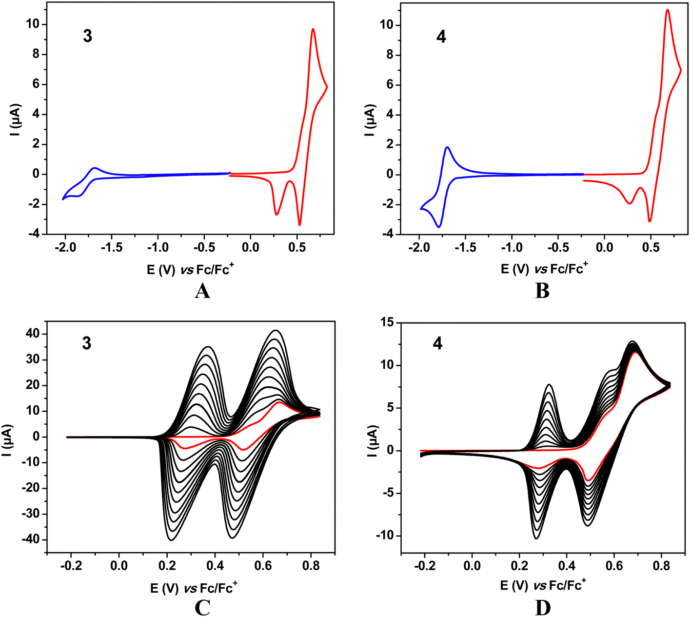 | ||
| Fig. 3 Cyclic voltammograms of 3 (A) and 4 (B). 10 consecutive oxidation cycles registered for 3 (C) and 4 (D). All CV recorded on a Pt disk working electrode. Red line – first oxidation scan. Concentration: 1 × 10⁻³ M; electrolyte: 0.1 M Bu4NPF6 solution in DCM; scan rate: 50 mV s−1. | ||
In the case of 3 and 4 consecutive scans yield anodic and cathodic peaks of increasing intensities, which is typical of dimerization or oligomerization processes in which the products are retained at the electrode. According to the most plausible mechanism the redox reaction starts by the formation of a radical cation in the D (9,9-dimethyl-9,10-dihydroacridine) unit which can exist in several resonant forms, some of them carrying unpaired spins in different positions of the aromatic ring. Recombination of two unpaired electrons followed by abstraction of two protons results in dimerization and in favorable conditions in further couplings leading to oligomerization.
In the case of 4 dimerization via the thienyl substituent could, in principle, be considered. This is, however, highly improbable, since the formation of a radical cation in α or β positions of a thienyl ring directly connected to a strongly electron accepting group requires high potentials which makes the resulting radical cation unstable and, by consequence, preventing it from any type of dimerization or oligomerization.36
Neutral molecule of 3 undergoes reduction at very similar potentials (E(0/1−) = −1.87 V) to 1. 4 is the easiest to reduce of all four molecules studied (E(0/1−) = −1.79 V) and its reduction process is the most reversible as judged from its cyclic voltammogram (Fig. 3). Redox potentials of 1 and 2 are listed in Table 1 whereas those of 3 and 4 in Table 2.
| Comp. | E(0/1−) [V] | E(1−/0) [V] | E(0/1−) onset [V] | E(0/2+) [V] | E(2+/1 +) [V] | E(1+/0) [V] | E(0/2+) onset [V] |
|---|---|---|---|---|---|---|---|
| 1 | −1.89 | −1.79 | −1.76 | 0.56 | 0.46 | 0.21 | 0.44 |
| 2 | −2.07 | −1.91 | −1.90 | 0.54 | 0.44 | 0.18 | 0.42 |
| Comp. | E(0/1−) [V] | E(1−/0) [V] | E(0/1−) onset [V] | E(0/1 +) [V] | E(1+/2 +) [V] | E(2+/1 +) [V] | E(1+/0) [V] | E(0/1 +) onset [V] |
|---|---|---|---|---|---|---|---|---|
| 3 | −1.87 | −1.69 | −1.71 | Shoulder | 0.68 | 0.53 | 0.28 | 0.47 |
| 4 | −1.79 | −1.69 | −1.68 | Shoulder | 0.69 | 0.49 | 0.28 | 0.47 |
Based on the obtained electrochemical data, ionization potential (IP), electron affinity (EA) and electrochemical band gap (Egel) values were calculated for all four compounds studied (see Table 3). Similar IPs and EAs of 1, 3 and 4 imply similar band gaps. 2 shows a wider band gap resulting from its measurably lower |EA|. These electrochemically determined parameters were confronted with the results of quantum chemical DFT calculations (vide infra).
Crystal structure of 1
Single crystals of compound 1 suitable for XRD measurements were obtained from its THF solution through slow evaporation of the solvent. Measurement and structure refinement details are given in the ESI.† Compound 1 crystallizes in P![[1 with combining macron]](https://www.rsc.org/images/entities/char_0031_0304.gif) space group with one molecule per asymmetric unit accompanied by two slightly disordered solvent molecules. The crystal structure is dominated by weak C–H⋯π interactions (Fig. 4).
space group with one molecule per asymmetric unit accompanied by two slightly disordered solvent molecules. The crystal structure is dominated by weak C–H⋯π interactions (Fig. 4).
 | ||
| Fig. 4 Molecular structure of compound 1. Thermal ellipsoids drawn at the 50% probability level. | ||
The geometry of 1 is unsymmetrical, yet the BTD core with directly attached phenylene rings closely resembles Cm symmetry. Inequivalent surrounding of the attached 9,9-dimethyl-9,10-dihydroacridine substituents results in distinctive differences in their geometry. The 9,9-dimethyl-9,10-dihydroacridine fragment interacts with the solvent molecules via C–H(solvent)⋯π(acridine) interactions stabilizing its planar geometry with the nearly ideal coplanarity of the phenyl rings. In the case of the second acridine substituent C–H(acridine)⋯O(THF) contacts are present and the acridine part adopts a slightly bent conformation with the phenyl ring planes forming an angle of 35°.
Acridine substituents exhibit nearly orthogonal mode with respect to the phenylene rings. Nearly identical N(acridine)–C(phenylene) bond lengths on both sides of the molecule (1.440(2) Å and 1.439(2) Å) indicate similar, low conjugation between the donor and the acceptor part of the molecule.
Quantum chemical calculations
DFT/B3LYP-GD3BJ/6-311++G(d,p) calculations were performed for the four studied compounds (1–4) with the goal to elucidate electron and structural contributions to their redox as well as luminescent properties and, in particular, to estimate the energies of the S1, T1, and T2 states. The calculations were performed for molecules in a vacuum and in dichloromethane (DCM) solutions. Fig. 5 presents the distribution of the calculated frontier orbitals. As seen from this figure, the LUMOs of 1–3 are mainly limited to the benzothiadiazole unit. Only in the case of 4, it is partly extended to the thienyl substituent. The distribution of HOMO is similar for all investigated molecules. In particular, the HOMO orbitals of 1 and 2 are strictly located at one of the (9,9-dimethyl-9,10-dihydroacridine) donors. The second (9,9-dimethyl-9,10-dihydroacridine) donor inhabits the HOMO−1 orbital. The HOMO of 4 is located on the two acridine groups with partial extension to the phenylene ring which links these groups. In the case of 3 it is located on two out of four acridine donor groups with no contribution to the linking aromatic ring, differing, however, in intensity. The HOMO−1 orbital is the mirror image of the HOMO one. For all investigated molecules the HOMO and LUMO are clearly separated in space. Thus, the LUMOs of 1, 2 and 3 are strictly limited to the benzothiadiazole central acceptor unit whereas the LUMO partially extends to the thienyl substituent in the case of 4. | ||
| Fig. 5 HOMO and LUMO contours calculated for 1–4 molecules in DCM using the DFT/B3LYP-GD3BJ/6-311++G(d,p) method. | ||
Electron parameters calculated for 1–4 molecules dissolved in DCM, whose geometries were optimized in this solvent, are collected in Table 4. The corresponding parameters obtained for the same molecules in a vacuum are presented in Table S4, ESI†). As seen from Table 4, the HOMO orbital of 2 is higher-lying than the corresponding HOMO orbitals of the remaining three molecules (1, 3, and 4), whose HOMO energy is very similar. The same trend is found for the LUMOs, i.e. the LUMO of 2 is located higher than the corresponding orbitals of 1, 3, and 4. For all compounds, the levels of the HOMO calculated for molecules in a vacuum are higher lying than those determined for molecules in the DCM solvent (see Table S4, ESI†). In contrast, the LUMOs calculated for the molecules in a vacuum are characterized by lower energies as compared to the ones calculated in the solvent. It should also be noted that DCM induces almost the same shift for the HOMO and LUMO energy levels. This can be rationalized by the fact that both orbitals are located on clearly defined, separated parts of the molecules.
| Molecule | HOMO (eV) | LUMO (eV) | E g (eV) | μ (D) | IPvertical (eV) | EAvertical (eV) | IPadiabatic (eV) | EAadiabatic (eV) |
|---|---|---|---|---|---|---|---|---|
| 1 | −5.48 | −2.89 | 2.62 | 1.81 | 5.46 | −2.83 | 5.36 | −2.96 |
| 2 | −5.31 | −2.80 | 2.51 | 1.72 | 5.32 | −2.74 | 5.26 | −2.90 |
| 3 | −5.47 | −2.93 | 2.54 | 2.04 | 5.43 | −2.90 | 5.32 | −2.90 |
| 4 | −5.46 | −2.96 | 2.50 | 2.35 | 5.42 | −2.94 | 5.31 | −3.09 |
The energy gap (difference between the HOMO and LUMO) is the highest for 1 (2.62 eV), but for the remaining molecules Eg being relatively close in values, decreasing in the following sequence: Eg(3) > Eg(2) > Eg(4). The same trend was found for molecules in a vacuum, but generally, the presence of DCM increases the values of Eg for all investigated molecules. DCM also affects the dipole moment values of 1–4. The calculated dipole moments decrease in the following order: 4 > 3 >1 > 2, 1 and 2 being rather similar. Thus, it can be postulated that an increase in the number of acridan donor units has a significant effect on the dipole moment value. The highest dipole moment of 4 is caused by the non-centrosymmetricity of the molecule. Since the dipole moments of 1 and 2 are similar, it can be postulated that the higher torsion between the donor and the acceptor moieties is caused by the presence of two methyl groups in the phenylene linker (2). In the case of 3 and 4, the steric hindrance associated with the presence of two acridan substituents in the phenylene linker leads to an increase of their electric dipole moment.
In addition to the energies of LUMO, HOMO, and dipole moments, Table 4 presents the calculated values of the ionization potentials (IP) as well as the electron affinities (EA) of 1–4. They were evaluated from the difference between the total energies of the neutral molecules and the energies of their respective radical ions. It should be noted that the calculated IPadiabatic values are in a very good agreement with the experimental ones (see Table 3) determined on the basis of cyclic voltammetry data, clearly showing the lowest experimental and theoretical values found for 2. In the case of EA better agreement between the experimental and the calculated data is found for EAvertical as compared to EAadiabatic. This leads to the conclusion that the reduction of the neutral molecule to the radical anion form does not change the molecular geometry, at least to the extent predicted theoretically (see Table S2 in the ESI†).
Optical properties of 1–4 were predicted using the time-dependent DFT (TDDFT) formalism with the methodology described in the ESI.† The parameters calculated for the geometries optimized in DCM are presented in Table 5. These include the first singlet (S1), its oscillator strength as well as the first and the second triplets (T1 and T2, respectively).
| Molecule | S1λmax (nm) | f | T1λmax (nm) | T2λmax (nm) | ΔE(S1–T1) (eV) | ΔE(S1–T2) (eV) |
|---|---|---|---|---|---|---|
| 1 | 550.84 | 0.0001 | 639.64 | 551.17 | 0.31 | 0.0013 |
| 2 | 572.86 | 0.0003 | 590.29 | 571.82 | 0.06 | −0.0039 |
| 3 | 585.67 | 0.0072 | 640.44 | 585.30 | 0.18 | −0.0013 |
| 4 | 590.26 | 0.0054 | 741.16 | 589.76 | 0.43 | −0.0018 |
The presented values are calculated in the vertical approach. In the works of Jacquemin et al.38,39 it was shown that the calculated excited state energies may depend on many factors, making the calculations rather difficult. Following the approach presented there we decided to calculate the Sn and Tn energies using the B3LYP functional and taking into consideration equilibrium solvent effects. Additionally, Nguyen and coworkers found that in the case of aromatic derivatives, the B3LYP functional frequently yields the energy of the T1–Tn transitions strictly in line with the experimental results.40 One should, however, be aware of the fact that these are approximate calculations and the results are not as precise as those obtained in the adiabatic approximation could be.41 Nevertheless, they undoubtedly are helpful in the interpretation of the obtained experimental data.
Wavelengths and oscillator strengths were calculated for the S0 → S1 transition with dominant HOMO → LUMO configurations. As seen in Fig. 5 (vide supra) the HOMO and LUMO of 1 and 2 are located on different parts of the molecule, which inhibits effective S0 → S1 transition. The oscillator strengths of these transitions are very small. The transition S0 → S2 for these molecules is also inefficient because the electron transition occurs from the second (9,9-dimethyl-9,10-dihydroacridine) donor to the benzothiadiazole acceptor. The transitions S0 → S1 and S0 → S2 for 1 and 2 are symmetric from the molecular orbital location point of view. The same applies to 3 and 4; in these cases, however, the HOMO orbitals are more diffused. Thus, the oscillator strengths are higher but the changes are not very significant. The lowest energy transition exhibiting high oscillator strength corresponds to the transition S0 → S3 for 1, 2, 4 and S0 → S5 for 3 with a dominant configuration HOMO−2 → LUMO and HOMO−4 → LUMO, respectively.
The values of ΔE(S1–T1) are positive for all four compounds studied whereas those of ΔE(S1–T2) are negative in the case of 2–4. A small energetic difference ΔE(S1–T1) equal to 0.06 eV calculated for 2 indicates the possible RISC process between T1 and S1 states. ΔE(S1–T1) values of the remaining three compounds fall within the range 0.18–0.43 eV, thus exceeding kT at room temperature. The chemical nature of the donor has a profound effect on the electronic and optical properties of benzothiadiazole-based DAD compounds. The case of 1 is instructive here. In this compound the distribution of the HOMO and LUMO as well as the energetic sequence of S1, T1 and T2 states is different than that presented by Chen et al.25 who investigated a donor–acceptor compound of the same A unit albeit differing in the chemical nature of the donors, namely diphenylamine instead of 9,9-dimethyl-9,10-dihydroacridine. On the other hand, the energetic difference ΔE(S1–T2) in compounds 2–4 is very small (0.001–0.004 eV), implying that T2 state is located in close proximity to S1. Energetic diagrams calculated for compounds 1–4 using the TDDFT method are presented in Fig. 6.
 | ||
| Fig. 6 Energy diagrams of molecules (a) 1, (b) 2, (c) 3, (d) 4 showing the first ten singlet and five triplet excited states calculated by using the TD method for the geometry optimized in DCM. | ||
Taking into account the results obtained by DFT calculations it can be predicted that the studied compounds can, in principle, exhibit interesting fluorescence properties. For all studied compounds the energy difference between S1 and T2 is smaller than that between S1 and T1. Thus, ISC and RISC between T2 and S1 states can effectively occur, improving the fluorescence quantum yield.
Photophysical properties
Absorption and in particular emission spectra of donor–acceptor compounds are frequently sensitive to the polarity of the solvent. Thus, in the case of 1–4, they were measured in non-polar toluene as well as in polar DCM at room temperature and at 5 K. The spectra registered for solutions in toluene are presented in Fig. 7 whereas those of DCM solution can be found in Fig. S13 of the ESI.† Two characteristic bands can be distinguished in the absorption spectra: (i) a more energetic band in the vicinity of 300 nm and (ii) a less energetic one in the 380–420 nm spectral range. The first band can be attributed to the π–π* transition whereas the second one can be ascribed to the S0 → S3 transition in the cases of 1, 2, 4 and to the S0 → S5 one for 3. Independently of the solvent (toluene or DCM) the experimentally determined maxima of the absorption bands were hypsochromically shifted as compared to their position calculated using DFT (see Fig. S12 in the ESI†). The Egopt values, both theoretically predicted and derived from the absorption spectra, are collected in Tables 4 and 6, respectively. | ||
| Fig. 7 Absorption (black) and fluorescence spectra of compounds 1–4 in toluene at room temperature (red) and fluorescence at 5 K (blue). | ||
| Compound | Solvent | λ absmax/λemmax nm | E g eV | Φ N2 % | Φ N2/Φair | Stokes shift [cm−1] |
|---|---|---|---|---|---|---|
| a Coumarine 153 in EtOH as a standard. | ||||||
| 1 | Toluene | 295, 382/574 | 2.65 | 37 | 1.37 | 8800 |
| DCM | 295, 381/738 | 1.0 | 12![[thin space (1/6-em)]](https://www.rsc.org/images/entities/char_2009.gif) 700 700 |
|||
| Powder | 283, 384/574 | 19 | 8600 | |||
| 2 | Toluene | 300, 356/540 | 2.88 | 7.3 | 1.92 | 9600 |
| DCM | 295, 357/728 | 0.65 | 14200 |
|||
| Powder | 294, 356/516 | 2.5 | 8700 | |||
| 3 | Toluene | 290, 379/622 | 2.70 | 0.7 | 1.40 | 10300 |
| DCM | 287, 377/765 | 0.09 | 13400 |
|||
| Powder | 285, 382/583 | 1.3 | 9000 | |||
| 4 | Toluene | 300, 418/610 | 2.58 | 1.1 | 1.57 | 7500 |
| DCM | 290, 416/766 | 0.06 | 11000 |
|||
| Powder | 291, 426/580 | 3.3 | 6200 | |||
The fluorescence spectra registered for solutions of 1–4 in a non-polar solvent (toluene) were rather broad (full width at half maximum, FWHM varied from 3300 cm−1 for 2 to 4000 cm−1 for 3) with no indication of any vibrational structure. They covered the spectral range of 540–620 nm. The use of a polar solvent (DCM) resulted in further broadening of the bands (FWHM increased to 3900 cm−1 in the case of 1 and to 4400 cm−1 for 2) and their bathochromic shift to the spectral range of 720–770 nm. Similar solvatochromic effects were observed for other acridan derivatives due to the twisted nature of these molecules.42 Independent of the solvent, the character of the emission indicated a CT-type luminescence.
An increase in the number of amine substituents attached to the phenylene linker (compounds 3 and 4) induced a bathochromic shift of the emission band as compared to the case of 1. The incorporation of two methyl groups into the phenylene linker (compound 2) resulted in an opposite effect, hypsochromically shifting the emission band. Large values of Stokes shifts determined from the spectra of 1–4 measured for their toluene and DCM solutions clearly confirmed the results of DFT calculations indicating electron excitations from S0 to S3 or S5 states.
The spectra of 1–4 registered at 5 K in both solvents showed hypsochromic shifts of the emission bands as compared to those recorded at RT, being shifted to the spectral range of 510–530 nm in frozen DCM and 480–510 nm in frozen toluene in all cases. The bands registered at 5 K were narrower indicating freezing of the conformational reorientations in the rigid matrices.
The positions of the fluorescence emission band in the solid state (powder) spectrum of 1 was essentially the same as that registered in toluene solutions at RT; its FWHM was, however, smaller (3200 cm−1). The emission bands in the solid state spectra of 2, 3 and 4 were hypsochromically shifted as compared to the corresponding bands recorded for their solutions in toluene (see Table 6 and Fig. 8). It should be noted that the band positions in the solid state spectra were close to those predicted by DFT calculations.
 | ||
| Fig. 8 Room temperature fluorescence spectra of compounds 1–4 in the solid state. | ||
When commenting on the photoluminescence quantum yield (PLQY), it should be noted that the PLQY values strongly depended not only on the chemical constitution of the studied compounds but also on their environment. The highest PLQY was measured for 1 in toluene solution and dropped significantly when measured in a solvent of much higher polarity (DCM). This is a common phenomenon in the case of DA and DAD compounds tested in solvents of increasing polarity, including previously studied acridan derivatives.42–45 The incorporation of two methyl groups in the 1,4-phenylene linker of 2 caused a 7-fold decrease of its PLQY as compared to the PLQY of 1. This decrease can be related to the steric hindrance between the donor and the acceptor units. The PLQY values measured for 3 and 4 were very small but increased for the solid state. Probably vibrationally induced emission quenching is partially suppressed in the solid state due to the intermolecular interaction confinement. Acridan derivatives can exists as two types of conformers, namely quasi-axial and quasi-equatorial;46,47 however, we did not observe any effect of conformation heterogeneity of the studied compounds, i.e. the presence of quasi-axial and quasi-equatorial conformers, on the solid state fluorescence spectra.
Finally, in the case of all studied compounds, the measured PLQY values for deoxygenated solutions were significantly higher than those determined for non-deoxygenated solutions (see Table 6). This can be considered as indicative of some contribution of triplet states to the observed fluorescence since the oxygen removal effectively impedes nonradiative quenching, favouring RISC.43–452 and 3 exhibited extremely weak phosphorescence (see the ESI,† Fig. S14) (ca. 3 orders of magnitude weaker than the fluorescence) at 5 K whereas in the case of 1 and 4 no phosphorescence was detected. The phosphorescence spectra were broad and shifted to lower energy by about 5000 cm−1 with respect to the corresponding fluorescence spectra, for 2 decays of this emission were 29 and 23 ms in toluene and DCM, respectively. Shorter decays were determined in the case of 3, namely 11 ms in toluene and 5 ms in DCM.
DFT calculations indicate that for all compounds studied, the T2 state is located in close proximity of the S1 state. However, a small energetic separation of T1 and T2 states excludes the formation of hot excitons, at least according to the idea postulated by Ma.24 A plausible reason for this is that sequence of states can have its origin in the geometry of the studied molecules, confirmed by DFT and in the case of 1 in its crystal structure. From this perspective, rigid 9,10-dihydro-9,9-dimethylacridine moiety being almost perpendicular to phenylene linker changes the distribution of the HOMO/LUMO and mutual positions of excited states contrary to that in 4,4′-(benzo[c][1,2,5]thiadiazole-4,7-diyl)bis(N,N-diphenylaniline), TPABTPA, proposed by Chen et al.25 On the other hand, a significant increase of PLQY in the degassed solution suggested some contribution of the triplet states in the process of fluorescence.
Conclusions
To summarize, following DFT predictions, we synthesized four benzothiadiazole derivatives containing 9,9-dimethyl-9,10-dihydroacridine substituents differently connected to the acceptor unit via a phenylene π-type linker. We demonstrated that by tuning the steric hindrance contribution we were able to obtain electrochemically active compounds exhibiting 1e quasi-reversible reduction. 1 and 2 could be oxidized to the dicationic state in a 2e oxidation accompanied oxidative dimerization. 3 and 4 electropolymerized upon oxidation. DFT calculations predicted that for all studied compounds T2 level is located in close proximity to S1. The investigated derivatives exhibited fluorescence in the orange-red spectral range showing broad emission bands typical of CT. PLQY, strongly dependent on the polarity of the solvent, significantly improved upon deoxygenation of the studied solutions. PLQY values measured for solid samples were also improved as compared to those determined for DCM solutions. These findings were rationalized via the partial suppression of the vibrationally induced emission quenching in the solid state due to the intermolecular interaction confinement.Data availability
The data that support the results of this study are openly available at https://doi.org/10.1039/d4cp02322f. Crystallographic data for compound 1 has been deposited at the CCDC under 2360338.Conflicts of interest
There are no conflicts to declare.Acknowledgements
This work was supported by the National Science Centre, Poland (NCN, Grant Opus No. 2022/45/B/ST5/02120).Notes and references
- Y. Zhang, Y. Wang, C. Gao, Z. Ni, X. Zhang, W. Hu and H. Dong, Chem. Soc. Rev., 2023, 52, 1331–1381 RSC.
- A. Anjali, R. Dheepika, P. M. Imran, N. S. P. Bhuvanesh and S. Nagarajan, ACS Appl. Electron. Mater., 2020, 2, 2651–2661 CrossRef CAS.
- J. Ma, Z. Liu, J. Yao, Z. Wang, G. Zhang, X. Zhang and D. Zhang, Macromolecules, 2018, 51, 6003–6010 CrossRef CAS.
- R. Rybakiewicz, J. Zapala, D. Djurado, R. Nowakowski, P. Toman, J. Pfleger, J. M. Verilhac, M. Zagorska and A. Pron, Phys. Chem. Chem. Phys., 2013, 15, 1578–1587 RSC.
- A. Pron, R. R. Reghu, R. Rybakiewicz, H. Cybulski, D. Djurado, J. V. Grazulevicius, M. Zagorska, I. Kulszewicz-Bajer and J. M. Verilhac, J. Phys. Chem. C, 2011, 115, 15008–15017 CrossRef CAS.
- M. C. Scharber and N. S. Sariciftci, Adv. Mater. Technol., 2021, 6, 2000857 CrossRef CAS.
- M. Mainville and M. Leclerc, ACS Energy Lett., 2020, 5, 1186–1197 CrossRef CAS.
- Y. Lin, Y. Li and X. Zhan, Chem. Soc. Rev., 2012, 41, 4245–4272 RSC.
- P. Bujak, I. Kulszewicz-Bajer, M. Zagorska, V. Maurel, I. Wielgus and A. Pron, Chem. Soc. Rev., 2013, 42, 8895–8999 RSC.
- J. Tao, H. Chen, Y. Han, L. Pu, X. P. Zhang, S. Peng, Z. Wu, H. Liu and J. Liu, Polymer, 2023, 285, 126386 CrossRef CAS.
- S. Singhal and A. Patra, Phys. Chem. Chem. Phys., 2020, 22, 1452714 RSC.
- S. Nad and S. Malik, ChemElectroChem, 2020, 7, 4144–4150 CrossRef CAS.
- P. Pander, A. Swist, P. Zassowski, J. Soloducho, M. Lapkowski and P. Data, Electrochim. Acta, 2017, 257, 192–202 CrossRef CAS.
- S. Orlandi, G. Pozzi, M. Cavazzini, D. Minudri, M. Gervaldo, L. Otero and F. Fungo, Macromolecules, 2015, 48, 4364–4372 CrossRef CAS.
- S. Hayashi and T. Koizumi, Polym. Chem., 2012, 3, 613–616 RSC.
- M. Icli, M. Pamuk, F. Algi, A. M. Onal and A. Cihaner, Chem. Mater., 2010, 22, 4034–4044 CrossRef CAS.
- R. Rybakiewicz, E. D. Glowacki, L. Skorka, S. Pluczyk, P. Zassowski, D. H. Apaydin, M. Lapkowski, M. Zagorska and A. Pron, Chem. – Eur. J., 2017, 23, 2839–2851 CrossRef CAS.
- R. Rybakiewicz, R. Ganczarczyk, M. Charyton, L. Skorka, P. Ledwon, R. Nowakowski, M. Zagorska and A. Pron, Electrochim. Acta, 2020, 358, 136922 CrossRef CAS.
- R. Rybakiewicz-Sekita, P. Toman, R. Ganczarczyk, J. Drapala, P. Ledwon, M. Banasiewicz, L. Skorka, A. Matyjasiak, M. Zagorska and A. Pron, J. Phys. Chem. B, 2022, 126, 4089–4105 CrossRef CAS.
- A. Spergen, A. Kalaisevan and S. Gokulnath, Adv. Opt. Mater., 2023, 11, 2300778 CrossRef CAS.
- P. M. Beaujuge, S. V. Vasilyeva, S. Ellinger, T. D. McCarley and J. R. Reynolds, Macromolecules, 2009, 42, 3694–3706 CrossRef CAS.
- J. Niu, Y. Wang, X. Zou, Y. Tan, C. Jia, X. Weng and L. Deng, Appl. Mater. Today, 2021, 24, 101073 CrossRef.
- F. B. Dias, J. Santos, D. R. Graves, P. Data, R. S. Nobuyasu, M. A. Fox, A. S. Batsanov, T. Palmeira, M. N. Barberan-Santos, M. R. Bryce and A. P. Monkman, Adv. Sci., 2016, 3, 1600080 CrossRef.
- Y. Xu, P. Xu, D. Hu and Y. Ma, Chem. Soc. Rev., 2021, 50, 1030–1069 RSC.
- X. Chen, Z. Yang, W. Li, Z. Mao, J. Zhao, Y. Zhang and Y. C. Wu, ACS Appl. Mater. Interfaces, 2019, 11, 39026–39034 CrossRef CAS.
- Y. Xu, X. Liang, X. Zhou, P. Yuan, J. Zhou, C. Wang, B. Li, D. Hu, X. Qiao, X. Jiang, L. Liu, S. J. Su, D. Ma and Y. Ma, Adv. Mater., 2019, 31, 1807388 CrossRef.
- C. T. Ziegenbein, S. Frcbel, M. Glcss, R. S. Nobuyasu, P. Data, A. Monkman and P. Gilch, Chem. Phys. Chem., 2017, 18, 2314–2317 CrossRef.
- W. Li, Y. Pan, R. Xiao, Q. Peng, S. Zhang, D. Ma, F. Li, F. Shen, Y. Wang, B. Yang and Y. Ma, Adv. Funct. Mater., 2014, 24, 1609–1614 CrossRef CAS.
- T. Liu, L. Zhu, C. Zhong, G. Xie, S. Gong, J. Fang, D. Ma and C. Yang, Adv. Funct. Mater., 2017, 27, 1606384 CrossRef.
- M. Shen, J. R. Lopez, J. Huang, Q. Liu, X. H. Zhu and A. J. Bard, J. Am. Chem. Soc., 2010, 132, 13453–13461 CrossRef CAS PubMed.
- P. Ledwon, P. Zassowski, T. Jarosz, M. Lapkowski, P. Wagner, V. Cherpak and P. Stakhira, J. Mater. Chem. C, 2016, 4, 2219–2227 RSC.
- N. A. Pushkarevsky, E. A. Chulanova, L. A. Shundrin, A. I. Smolentsev, G. E. Salnikov, E. A. Pritchina, A. M. Genaev, I. G. Irtegova, I. Y. Bagryanskaya, S. N. Konchenko, N. P. Gritsan, J. Beckmann and A. V. Zibarev, Chem. Eur. J., 2019, 25, 806–816 CrossRef CAS PubMed.
- N. P. Tripathi, V. Gupta, T. Tarun, U. K. Pandey and S. Sengupta, Chem. Eur. J., 2023, 29, e202203951 CrossRef PubMed.
- R. Rybakiewicz, R. Ganczarczyk, G. Wiosna-Salyga, I. Bobowska, M. Banasiewicz, M. Charyton, L. Skorka, M. Zagorska and A. Pron, Opt. Mater., 2020, 108, 110428 CrossRef CAS.
- T. L. Andrew and T. M. Swager, J. Org. Chem., 2011, 76, 2976–2993 CrossRef CAS PubMed.
- A. S. Fisyuk, R. Demadrille, C. Querner, M. Zagorska, J. Bleuse and A. Pron, New J. Chem., 2005, 29, 707–7013 RSC.
- J. Sworakowski, Synth. Met., 2018, 235, 125–130 CrossRef CAS.
- D. Jacquemin, I. Duchemin and X. Blase, J. Chem. Theory Comput., 2015, 11, 5340–5359 CrossRef CAS.
- A. D. Laurent and D. Jacquemin, Int. J. Quant. Chem., 2013, 113, 2019–2039 CrossRef CAS.
- K. A. Nguyen, J. Kennel and R. Pachter, J. Chem. Phys., 2002, 117, 7128–7136 CrossRef CAS.
- P. F. Loos and D. Jacquemin, J. Chem. Theory Comput., 2019, 15, 2481–2491 CrossRef CAS.
- J. Massue, L. Diarra, I. Georgoulis, A. Fihey, F. Robin-le-Guen, G. Ulrich, M. Fakis and S. Achelle, ChemPhotoChem, 2023, e202300085 CrossRef CAS.
- I. Kulszewicz-Bajer, M. Zagorska, M. Banasiewicz, P. A. Gunka, P. Toman, B. Kozankiewicz, G. Wiosna-Salyga and A. Pron, Phys. Chem. Chem. Phys., 2020, 22, 8522–8534 RSC.
- E. M. Ungureanu, M. L. Tatu, E. Georgescu, C. Boscornea, M. M. Papa and G. Stanciu, Dyes Pigments, 2020, 174, 108023 CrossRef CAS.
- W. Xie, B. Li, X. Cai, M. Li, Z. Qiao, X. Tang, K. Liu, C. Gu, Y. Ma and S. J. Su, Front. Chem., 2019, 7, 276 CrossRef CAS PubMed.
- K. Stavrou, L. G. Franca, T. Bohmer, L. M. Duben, C. M. Marian and A. P. Monkman, Adv. Funct. Mater., 2023, 33, 2300910 CrossRef CAS.
- M. Hode, J. Massue, S. Achelle, A. Fihey, D. Tondelier, G. Ulrich, F. Robin-le-Guen and C. Katan, Phys. Chem. Chem. Phys., 2023, 25, 32699–32708 RSC.
Footnote |
| † Electronic supplementary information (ESI) available. CCDC 2360338. For ESI and crystallographic data in CIF or other electronic format see DOI: https://doi.org/10.1039/d4cp02322f |
| This journal is © the Owner Societies 2024 |