Cu-doped LaNiO3 perovskite catalyst for DRM: revisiting it as a molecular-level nanocomposite†
Received
1st June 2024
, Accepted 16th September 2024
First published on 20th September 2024
Abstract
Dry reforming of methane (DRM) was extensively studied on Cu-doped LaNiO3 catalysts. The main findings of this work are as follows: (i) thermal switching of the catalyst phase between the parent perovskite and molecular-level nanocomposite of individual components formed in situ during DRM, (ii) reusability of the catalyst with enhanced activity, and (iii) regeneration of the catalyst phase at a lower temperature than that required for the formation of the parent perovskite. The present investigation provides an extensive analysis and understanding of the DRM reaction using Cu-doped LaNiO3 compared to the result reported by Moradi et al., (Chin. J. Catal., 2012, 33, 797–801) and hence provides new insights into its catalytic activity. Phase-pure LaNi1−xCuxO3 catalysts, specifically LaNi0.8Cu0.2O3, exhibited high catalytic activity towards the DRM reaction (97% CH4 and 99% CO2 conversion with an H2/CO ratio of ∼1.4–0.9). Remarkably, although the initial perovskite phase primarily decomposed into its component phases after DRM, its catalytic activity was barely affected and maintained even after 100 h. The regeneration of the initial perovskite from the disintegrated binary phases via annealing at temperatures even lower than the synthesis temperature together with the amazing retention of activity was very intriguing. The parallel activity of the pristine perovskite and its degraded binary mixtures makes it difficult to identify the actual components responsible for the DRM activity. Accordingly, we have explained the sustained activity of the degraded perovskite catalyst in the context of nanocomposite formation at the molecular level in the reforming atmosphere with the availability of Ni0 and NiO, as revealed by the thoroughly characterized samples in the as-prepared, aged, and regenerated forms.
1. Introduction
Energy generated from fossil fuels is limited compared to the demand of daily activities in modern life, making it necessary to explore other possible sources of energy. Furthermore, the indiscriminate use of fossil fuels has resulted in an imbalance in the environment. Especially, greenhouse gases, predominantly CH4 and CO2, produced from the burning of fossil fuels threaten human health. According to extensive research carried out in the last several years, green H2 energy can be one of the potential substitutes for fossil fuels. Currently, hydrogen energy is regarded as a future energy source owing to its extremely ecofriendly nature and high energy output. For the production of H2, a number of catalytic processes are available, including dry reforming of methane (DRM), steam reforming of methane (SRM), photochemical, photoelectrochemical, and electrochemical processes. Among them, DRM is one of the most commonly used methods because of the ease of catalyst synthesis, low cost, and prolonged catalyst activity. It has the additional benefit of consuming two significant greenhouse gases (CH4 and CO2) while generating effective feedstock syngas (H2 + CO) and producing H2 at a relatively higher rate. In recent years, DRM has attracted the attention of industrial and academic researchers for its numerous applications in industry,1,2 environment fields3–7 and academic studies.8,9 Syngas is used for a variety of purposes, such as H2 production,10–13 diesel production via the Fischer–Tropsch method,14,15 preparation of methanol,16–18 and reduction of iron ore to get sponge iron.19–21 However, the DRM reaction has some major drawbacks such as coke deposition22–25 and instability of the catalyst in the reaction atmosphere. The DRM process involves the following reactions:16,26–32| | | Methane reforming: CH4 + CO2 ↔ 2CO + 2H2 ΔH = 247 kJ mol−1 | (1) |
| | | Reverse water gas shift reaction: CO2 + H2 ↔ H2O + CO ΔH = 41 kJ mol−1 | (2) |
| | | Methane cracking: CH4 ↔ C + 2H2 ΔH = 75 kJ mol−1 | (3) |
| | | Boudouard reaction: 2CO ↔ C + CO2 ΔH = −172 kJ mol−1 | (4) |
According to the aforementioned reactions, it can be concluded that CH4 cracking (eqn (3)) and CO decomposition (eqn (4)) are the main causes of coke deposition. Among the transition metal oxide-based catalysts, nickel-containing catalysts are generally highly active and durable for the DRM reaction. Noble metal catalysts such as Ru,33–35 Pt,36–38 and Rh39–42 are also highly active, stable, and produce lower amounts of coke during DRM. However, although noble metal catalysts show excellent catalytic activity in DRM, they are not considered because of their high cost and small-scale availability. Alternatively, transition metal oxide-based catalysts are excellent replacements for noble metal catalysts given that they are more affordable and widely available. The primary issue with nickel-based catalysts is that they are prone to coking, which causes the active phase to quickly deactivate and reduces the reactivity and durability of the catalysts during the DRM reaction. Transition metal oxide-based catalysts must also be modified to increase their catalytic activity, durability, and coke resistance or reduce coke deposition. Due to the crucial role played by the catalyst in the reaction medium, substantial research has been conducted globally to develop promising catalyst systems with high catalytic activity, high durability, and high coking resistance.
The scientific community has focused on formulating some suitable modified transition metal-based oxide catalysts such as perovskite, spinel, hercynite, and pyrochlore for the DRM reaction. Shahnazi et al. showed the effect of partial substitution of Ni by Mn in the LaNi1−xMnxO3 perovskite catalyst43 synthesized via ultrasonic spray pyrolysis on the DRM reaction for 10 h in the temperature range of 600 °C to 800 °C. They obtained ∼50% CH4 conversion and 85% CO2 conversion with an H2/CO ratio of 1.1. The gas hourly space velocity (GHSV) of the input gases was 15![[thin space (1/6-em)]](https://www.rsc.org/images/entities/char_2009.gif) 000 mL gcat−1 h−1. Jahangiri et al. synthesized an Fe-substituted LaNiO3 catalyst44via the sol–gel method and analysed its catalytic role. They investigated the activities of the catalyst as a function of temperature in the range of 600–800 °C. Their results revealed that all the doped systems were comparatively less active in terms of DRM activity for 20 h. Kim et al. prepared an LaNi0.34Co0.33Mn0.33O3 catalyst30 modified with Co and Mn at the B site via a microwave-assisted Pechini method to investigate the role of tri-metal substitution at the B site, keeping the A site constant. Almost 92% CH4 conversion was achieved (GHSV = 12000 mL gcat−1 h−1), but the activity of the catalyst was only stable for 14 h. Valderrama et al. reported the synthesis of the LaNi1−xMnxO3 catalyst,45 doping Mn at the Ni site and tested its DRM activity. The as-prepared LaNi0.2Mn0.8O3 catalyst showed the highest activity at 750 °C, reaching CH4 and CO2 conversion of 77% and 84%, respectively, with an H2/CO ratio close to unity at GHSV of 15000 mL gcat−1 h−1. Hu et al. showed the catalytic role of the Ni/MgO catalyst in the dry reforming of methane.46 In their report, the observed conversions of CH4 and CO2 were 91% and 98%, respectively, and the H2/CO ratio was 0.92 for 120 h of reaction at GHSV of 60000 mL gcat−1 h−1. A similar study was performed by Song et al. by doping Mo in the Ni/MgO catalyst.47 Their Ni–Mo/MgO catalyst was durable for as long as 850 h with 75% CH4 and 80% CO2 conversion and the H2/CO ratio was reported to be 0.86 at GHSV of 60000 mL gcat−1 h−1. Wang et al. reported the DRM activity of La(CoxNi1−x)0.5Fe0.5O3,48 where the H2/CO ratio was reported to be 0.92 with CH4 and CO2 conversions of 70% and 80%, respectively, for x = 0.1 composition at GHSV of 36000 mL gcat−1 h−1. In an earlier report, Moradi et al. reported the catalytic activity in the DRM reaction of Cu-doped LaNiO3 prepared via the sol–gel method using propanoic acid as fuel.49 The 20% Cu-doped sample, LaNi0.8Cu0.2O3, was reported to be the most active catalyst, converting 73% of CH4 and 90% of CO2 with an H2/CO ratio of 0.8. However, they tested their catalyst for only 20 h and the decomposition of the parent Cu-substituted perovskite to individual oxides and metallic Ni was observed. Also, further studies on this catalyst system pertaining to its phase regeneration, i.e., its long-term durability pattern, were not performed, which was supposed to show high DRM activity. In this regard, it will be worth exploring Cu-doped LaNiO3 catalysts for their DRM activity in detail by synthesizing materials via various routes. Thus, in this study, extensive characterization of the pristine, aged and regenerated catalysts was carried out to understand the origin of their activity and establish structure–activity correlations. The findings indicated that the catalyst synthesized via the sol–gel route was superior to that prepared via the solution combustion synthesis and conventional ceramic processes. It was also observed that the DRM activity was sustained even after decomposition of the pristine catalysts into simple binary oxides of their constituent elements together with metallic nickel, resulting a molecular-level nanocomposite a couple of hours after the commencement of the catalysis reaction. Most importantly, the starting catalyst phase could be easily regenerated from the decomposed phases through in situ oxidation at a temperature lower than that required for the synthesis of the parent perovskite. This reversibility of the pure and decomposed phases of the aged catalyst by in situ thermal treatment is a remarkable outcome of this study. The origin of these thermally switchable catalysts with very efficient conversion ability was explained based on the plausible microstructural viewpoint of Cu-doped LaNiO3 perovskite catalysts.
000 mL gcat−1 h−1. Jahangiri et al. synthesized an Fe-substituted LaNiO3 catalyst44via the sol–gel method and analysed its catalytic role. They investigated the activities of the catalyst as a function of temperature in the range of 600–800 °C. Their results revealed that all the doped systems were comparatively less active in terms of DRM activity for 20 h. Kim et al. prepared an LaNi0.34Co0.33Mn0.33O3 catalyst30 modified with Co and Mn at the B site via a microwave-assisted Pechini method to investigate the role of tri-metal substitution at the B site, keeping the A site constant. Almost 92% CH4 conversion was achieved (GHSV = 12000 mL gcat−1 h−1), but the activity of the catalyst was only stable for 14 h. Valderrama et al. reported the synthesis of the LaNi1−xMnxO3 catalyst,45 doping Mn at the Ni site and tested its DRM activity. The as-prepared LaNi0.2Mn0.8O3 catalyst showed the highest activity at 750 °C, reaching CH4 and CO2 conversion of 77% and 84%, respectively, with an H2/CO ratio close to unity at GHSV of 15000 mL gcat−1 h−1. Hu et al. showed the catalytic role of the Ni/MgO catalyst in the dry reforming of methane.46 In their report, the observed conversions of CH4 and CO2 were 91% and 98%, respectively, and the H2/CO ratio was 0.92 for 120 h of reaction at GHSV of 60000 mL gcat−1 h−1. A similar study was performed by Song et al. by doping Mo in the Ni/MgO catalyst.47 Their Ni–Mo/MgO catalyst was durable for as long as 850 h with 75% CH4 and 80% CO2 conversion and the H2/CO ratio was reported to be 0.86 at GHSV of 60000 mL gcat−1 h−1. Wang et al. reported the DRM activity of La(CoxNi1−x)0.5Fe0.5O3,48 where the H2/CO ratio was reported to be 0.92 with CH4 and CO2 conversions of 70% and 80%, respectively, for x = 0.1 composition at GHSV of 36000 mL gcat−1 h−1. In an earlier report, Moradi et al. reported the catalytic activity in the DRM reaction of Cu-doped LaNiO3 prepared via the sol–gel method using propanoic acid as fuel.49 The 20% Cu-doped sample, LaNi0.8Cu0.2O3, was reported to be the most active catalyst, converting 73% of CH4 and 90% of CO2 with an H2/CO ratio of 0.8. However, they tested their catalyst for only 20 h and the decomposition of the parent Cu-substituted perovskite to individual oxides and metallic Ni was observed. Also, further studies on this catalyst system pertaining to its phase regeneration, i.e., its long-term durability pattern, were not performed, which was supposed to show high DRM activity. In this regard, it will be worth exploring Cu-doped LaNiO3 catalysts for their DRM activity in detail by synthesizing materials via various routes. Thus, in this study, extensive characterization of the pristine, aged and regenerated catalysts was carried out to understand the origin of their activity and establish structure–activity correlations. The findings indicated that the catalyst synthesized via the sol–gel route was superior to that prepared via the solution combustion synthesis and conventional ceramic processes. It was also observed that the DRM activity was sustained even after decomposition of the pristine catalysts into simple binary oxides of their constituent elements together with metallic nickel, resulting a molecular-level nanocomposite a couple of hours after the commencement of the catalysis reaction. Most importantly, the starting catalyst phase could be easily regenerated from the decomposed phases through in situ oxidation at a temperature lower than that required for the synthesis of the parent perovskite. This reversibility of the pure and decomposed phases of the aged catalyst by in situ thermal treatment is a remarkable outcome of this study. The origin of these thermally switchable catalysts with very efficient conversion ability was explained based on the plausible microstructural viewpoint of Cu-doped LaNiO3 perovskite catalysts.
2. Experimental
2.1. Chemicals
For the synthesis of the requisite series of LaNi1−xCuxO3 (x = 0.1, 0.2, 0.3, 0.4, 0.6, and 0.8) materials the corresponding metal nitrate salts, La(NO3)3·6H2O (Spectrochem, purity >99.99%), Ni(NO3)2·6H2O (Merck, purity >98%), Cu(NO3)2·3H2O (Sigma Aldrich, purity ≥98%), and citric acid monohydrate, C6H8O7·H2O (Merck, purity >99%), which served as the purposed fuel and chelating agent, were used as-received. The solvent in the synthetic procedure was Millipore water (ultra-pure water).
2.2. Preparation of materials
Sol–gel synthesis was used to produce a series of LaNi1−xCuxO3 (x = 0.1, 0.2, 0.3, 0.4, 0.6, and 0.8, named CuXLNO, X = 10–80, the atom percentage of Cu-doping, i.e., X = 100x) perovskite-like materials, as shown schematically in Scheme S1 (ESI†). Stoichiometrically, the relevant metal nitrates were added to a beaker containing 50–60 mL of Millipore water, and then stirred for around 2 h to dissolve the metal nitrates thoroughly and form a homogeneous solution. To stop the metal ions from being hydrolysed, the solution was given a 2 mL boost of concentrated nitric acid. Subsequently, the homogenous solution was stirred, while a stoichiometric amount of citric acid monohydrate was added to the solution, which served as a chelating agent and fuel (metal:citric acid = 1:4 molar ratio). Specifically, for the preparation of Cu20LNO, 1.763 g of La(NO3)3·6H2O, 0.196 g of Cu(NO3)2·3H2O, 0.947 g of Ni(NO3)2·6H2O, and 7.6905 g of C6H8O7·H2O were added. After vigorous swirling, the resultant solution was left overnight to form a homogenous mixture. The metal–citrate gel was formed by heating it to 80–100 °C for around 50 min, during which time the water evaporated, where the heating rate was ∼10 °C min−1. After completion of evaporation, the xerogel began to gradually break apart into a fluffy pile. Subsequently, the fluffy mass was ground to a powder using a mortar and pestle and calcined at 800 °C for 3 h in static air in a muffle furnace at a heating rate of 10 °C min−1 to remove the nitrate residue and other types of impurities, obtaining the appropriate selective samples.
To compare the catalytic activity of the Cu20LNO catalyst, the solution combustion synthesis (SCS) method was also used to prepare a catalyst named Cu20LNO SCS. The preparation of Cu20LNO SCS involved the combustion of a stoichiometric composition of metal nitrate salts with organic fuel, typically 1.732 g of La(NO3)3·6H2O, 0.1928 g of Cu(NO3)2·3H2O, 0.93 g of Ni(NO3)2·6H2O, and 2.5 g of organic fuel, oxalyldihydrazide (C2H6N4O2, ODH) (Merck India) dissolved in the minimum volume of Millipore water in a borosilicate dish. Then, the homogenized solution was transferred into a preheated muffle furnace controlled at ∼600 °C. Initially, the solution started boiling with frothing and foaming, leading to the formation of a fluffy mass within a few minutes after complete dehydration. Using a mortar and pestle, the fluffy mass was thoroughly ground into powder to get the Cu20LNO SCS catalyst.
2.3. Characterization
The perovskite phase of the nano-sized perovskites was confirmed by powder X-ray diffraction (XRD). The XRD diffraction pattern of each sample was recorded using a Bruker D8 Advance diffractometer with CuKα radiation (λ = 1.5418 Å) generated at 40 kV and 40 mA using a 1D position-sensitive LYNXEYE detector at a scan rate of 1 s per step in the 2θ range of 10° to 80°.
The textural properties, namely specific surface area (SBET), pore volume, and pore size (as well its distribution), were measured using N2 sorption isotherms in an Autosorb iQ2 gas sorption apparatus (Quantachrome Instruments, USA). Prior to the measurement, the catalyst sample was degassed at 100 °C for 4 h in a FLOVAC degasser tube under vacuum (0.3 Torr). The multi-point BET technique was used to calculate the surface area, while the non-local density functional theory (NLDFT) approach was used to calculate the pore size distribution and pore volume of the catalysts.
Field emission scanning electron microscopy (FESEM) and energy dispersive X-ray analysis (EDX) (JEOL, Model: JSM-5600LV (Japan)) were used to evaluate the surface morphology and elemental composition of the catalysts, respectively.
High resolution transmission electron microscopy (HRTEM) analysis (JOEL, Model: JEM-2100 (Japan)) was performed to investigate the surface morphology and microstructure of the catalysts at an accelerating voltage of 200 kV.
Two chosen catalysts were subjected to X-ray photoelectron spectroscopy (XPS) for surface characterization using a SPECS spectrometer with an AlKα source (1486.6 eV) operated at 150 W and a Phoibos 150 MCD-9 detector and analysis chamber with a pressure below 10−7 Pa. The samples were pressed into pellets with a diameter of 10 mm and a sample region of 2 mm × 2 mm was examined. The pass energy and energy step of the hemispherical analyzer were set at 25 eV and 0.1 eV, respectively. A SPECS Flood Gun FG 15/40 was used to stabilise the charge. With reference to the C 1s binding energy value of 284.8 eV, the data were analysed using the PeakFit v4.12 software.
Thermogravimetric analysis (TGA) was performed using a PerkinElmer Pyris Diamond TG/DTA instrument to ascertain the coke deposited on the surface of the aged sample during the DRM. The sample was heated to 900 °C at a heating rate of 10 °C min−1 in an N2 environment.
2.4. Catalytic activity test
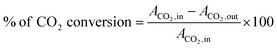
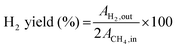
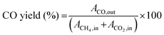
The DRM tests were carried out in a reaction set up fabricated in our laboratory, the details of which can be found in a recent report in the literature.50 In short, the DRM reaction was carried out at 800 °C by adding 100 mg of catalyst (mesh size of ≈85–100) in a down flow quartz micro-reactor placed vertically in a tubular furnace. CH4 and CO2 were mixed in a 1:1 (mol mol−1) ratio using helium as the carrier gas and a diluting agent (total flow = 56 mL min−1) with the CH4:CO2:He ratio of 1:1:3.6 to maintain a GHSV of 34000 mL gcat−1 h−1. All the gases used for the DRM reaction were of ultrahigh purity grade (99.999%). The gaseous mixture from the reactor outlet was analysed using a quadrupole mass spectrometer (OMNIStar gas analysis system), which gave the ion current (A) values against the specific m/z (m = mass of the gas, z = charge on the ion) value of the component gases (X) from the gaseous mixture. The CH4 and CO2 conversion values were calculated using the formula below considering the initial (i.e., before reaction, AX,in) and steady-state (after ∼1 h of reaction at a particular temperature (AX,out) ion current values for each component X with a fixed m/z value.| | 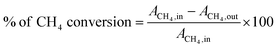 | (5) |
| |  | (6) |
| |  | (7) |
| |  | (8) |
| |  | (9) |
| |  | (10) |
The H2/CO ratio was calculated from the ratio of  for each ion current value. The reproducibility of the experimental data was verified, which suggested the experimental error was within ±3%. It should be mentioned that there was no need to rectify the m/z = 28 amu signal for CO2 cracking or the CH4 cracking contribution to the production of H2.
3. Results and discussion
3.1. Powder XRD analyses of the as-prepared perovskite catalysts
The powder XRD patterns of CuXLNO (X = 10–80) are presented in Fig. 1, where it is evident that up to x = 0.6, the pure perovskite phase was achieved. Subsequently, the anticipated perovskite phase appeared together with certain impurities, including NiO, CuO, and La2O3, as the concentration of Cu increased. The diffraction peaks of the primary LaNi1−xCuxO3 phase are observed at the 2θ values of 23.2°, 32.7°, 33.4°, 41.4°, 42.3°, 47.2°, 52.6°, 53.2°, 58.6°, 59.5°, 68.6°, 69.7°, 78°, and 79.4°, which match the lattice planes of (012), (110), (104), (202), (006), (024), (122), (116), (214), (018), (220), (208), (134), and (128), respectively, of the perovskite (JCPDS PDF2 # 880633). The Scherrer sizes of the as-prepared LNO, Cu10LNO, Cu20LNO, Cu30LNO, Cu40LNO, Cu60LNO, and Cu80LNO samples are 16.2, 23.9, 24.2, 23.3, 17.4, 56, and 63 nm, respectively. The peaks at the 2θ values of 27.3° and 31.2° correspond to La2O3, at 43.2° to NiO and 36.2°, 39.4° and 49° to CuO impurities. No impurity phases were detected at lower Cu-doping. However, the impurity-related peaks became apparent at higher Cu-doping percentages over 60%.
 |
| | Fig. 1 Powder XRD patterns of as-prepared CuXLNO (X = 10–80, the atom percentage of Cu doping) perovskite materials. | |
3.2. Screening of materials for DRM
All the as-prepared samples were subjected to an initial catalytic activity test for 10 h to determine the best catalyst and their catalytic activity is shown in Fig. 2(a)–(c). The CH4 conversion by the as-prepared LNO, Cu10LNO, Cu20LNO, Cu30LNO, Cu40LNO, Cu60LNO, and Cu80LNO samples was 72%, 92%, 97%, 93%, 92%, 80%, and 77%, respectively. The corresponding CO2 conversion by the samples was 85%, 95%, 99%, 97%, 93%, 91%, and 90%, respectively. In all cases, the H2/CO ratio for this catalytic reaction was found to vary from 0.6 to 1.9. Thus, it is evident that all the doped catalysts showed superior DRM catalytic activities to the parent LNO system, which followed the order of Cu20LNO > Cu30LNO > Cu40LNO > Cu10LNO > Cu60LNO > Cu80LNO > LNO. Thus, by partially replacing Ni with Cu in LaNiO3, all the as-prepared catalysts belonging to the perovskite series demonstrated higher catalytic activities than the parent LNO, among which Cu20LNO showed the highest activity toward DRM. In this regard, the atomic percentage of Cu-doping was significant.
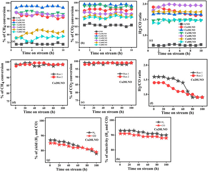 |
| | Fig. 2 Catalytic activities of as-prepared CuXLNO (X = 0–80) perovskite materials for 10 h (upper panel) and 100 h (middle panel) of the DRM reaction: (a) and (d) CH4 conversion, (b) and (e) CO2 conversion, (c) and (f) H2/CO ratio, and (g) and (h) H2/CO yield and selectivity, respectively (reaction conditions: CH4:CO2:He = 1:1:3.6, GHSV = 34000 mL gcat−1 h−1, 800 °C). | |
To shed further light on the Cu20LNO perovskite catalyst system and determine its durability in the reforming atmosphere, a constant 100 h DRM reaction was conducted using this catalyst. The CH4 conversion, CO2 conversion, and H2/CO ratio of the Cu20LNO catalyst are shown in Fig. 2(d)–(f) for 100 h DRM reaction, respectively. According to the conversion graph, Cu20LNO demonstrated the remarkable conversion of 97% for CH4 and 99% for CO2 over the duration of DRM reaction lasting 100 h, with the H2/CO ratio ranging from 1.4 to ∼0.9. The fact that the H2/CO ratio first exceeded unity indicates the existence of the Boudouard reaction (eqn (4)), where CO was transformed to carbon and carbon dioxide. As a result, the total amount of CO was reduced and the H2/CO ratio reached 1.4 within the first 10 h of the reaction. Coke deposition in the reaction medium often causes the reaction to slow down, but the Boudouard and reverse Boudouard reactions occur simultaneously, efficiently supporting the catalytic activity of the catalyst in the reaction medium. As projected, the H2/CO ratio gradually approached unity. The H2/CO ratio value greater than unity was also thought to originate from the methane cracking process. However, in that case, there should have been a decrease in methane conversion due to hindrance by coke formed via cracking, as previously reported in the literature.50 The fact that the deposited coke had no effect on the reaction activity suggests that the Boudouard reaction is the key factor for a higher H2/CO ratio rather than methane cracking. The yield of H2 was in the range of 87% (at the beginning of reaction) to 78% at the end of 100 h DRM reaction, whereas the CO production varied from 85% to 79% during this time on stream activity. The variation in H2 selectivity was minimal, maintaining an average value of 92% with an average CO selectivity of 90%. The reaction was terminated after 100 h of continuous operation, and the aged catalyst was cooled in a helium atmosphere to room temperature. To determine the changes in the catalyst after the DRM reaction and comprehend the structure–activity correlation, the aged catalyst was characterized thoroughly and compared with the as-prepared catalyst (Table 1).
Table 1 DRM reaction data of as-prepared catalysts
| Catalyst |
CH4 conversion (%) |
CO2 conversion (%) |
H2/CO ratio |
| 10 h |
100 h |
10 h |
100 h |
10 h |
100 h |
| Cu10LNO |
92 |
— |
95 |
— |
1.7 |
— |
| Cu20LNO |
97 |
97 |
99 |
99 |
1.4 |
0.9 |
| Cu30LNO |
93 |
— |
97 |
— |
1.5 |
— |
| Cu40LNO |
92 |
— |
93 |
— |
1.9 |
— |
| Cu60LNO |
77 |
— |
91 |
— |
1.7 |
— |
| Cu80LNO |
75 |
— |
90 |
— |
1.4 |
— |
| LNO |
72 |
— |
85 |
— |
0.7 |
— |
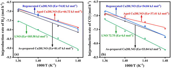
The apparent activation energies of the reforming reaction associated with the various forms of Cu20LNO and pristine LNO were calculated to correlate them with the activity data. In the kinetic investigations, the fixed-bed flow reactor was loaded with 30 mg of catalyst that had been diluted with 70 mg of purified silica of the same mesh size (85–100), keeping the other experimental conditions unchanged. The temperature was varied in the range of 400–460 °C to keep the conversion below 20%. The Arrhenius plots of LNO and the various Cu20LNO catalysts are shown in Fig. 3. The apparent activation energies (considering the formation rates of H2 in the above-mentioned temperature range) calculated from the slopes of the Arrhenius plots are 105.5 kJ mol−1 for LNO, 81.5 kJ mol−1 for the as-prepared Cu20LNO, 66.7 kJ mol−1 for the aged Cu20LNO, and 74.8 kJ mol−1 for the regenerated Cu20LNO (see Fig. 3(a)). Noticeably, the calculated apparent activation energies for the production of CO were comparatively lower than that for the production of H2, which are 72.7 kJ mol−1 (LNO), 54.0 kJ mol−1 (as-prepared Cu20LNO), 37.3 kJ mol−1 (aged Cu20LNO) and 54.0 kJ mol−1 (regenerated Cu20LNO) (see Fig. 3(b)). It is evident that pure LNO had the maximum activation energy (105.5 kJ mol−1 and 72.7 kJ mol−1 for H2 and CO production) and the aged form of the Cu20LNO catalyst had the lowest activation energy barrier (66.7 kJ mol−1 and 37.3 kJ mol−1 for H2 and CO production) among the different forms of the catalyst, respectively. Thus, it can be concluded that once aged, the Cu20LNO catalyst transforms into its most activated form. Although higher than the aged catalyst, the regenerated form of the catalyst also has a lower apparent activation energy value than the as-prepared catalyst.
 |
| | Fig. 3 Arrhenius plots for the production of (a) H2 and (b) CO for LNO, as-prepared Cu20LNO, aged Cu20LNO, and regenerated Cu20LNO catalysts (reaction conditions: CH4:CO2:He = 1:1:3.6 and GHSV = 113300 mL gcat−1 h−1). | |
3.3. Powder XRD analyses of various forms of Cu20LNO catalyst: relationship with the DRM activity behaviour
Fig. 4 shows the powder XRD patterns of all forms of the Cu20LNO catalyst. It clearly proves that the characteristic diffraction pattern of the perovskite phase was completely suppressed with the appearance of several diffraction peaks in aged sample. These new peaks correspond to the simple binary oxide phases, as assigned in the figure, which obviously emerged due to the degradation of the original perovskite phase. It can also be pointed out that the same structural transformation (powder XRD patterns not included here) was observed after 10 h of reaction. These phases exactly correspond with ICDD PDF # 831349 for La2O3 (*), 897128 for Ni (○), 140481 for NiO (●), 782076 for CuO (◊), and 832034 for La(OH)3 (■). Numerous studies have demonstrated that the catalyst typically breaks down into its component oxides in the reaction environment,26,35,37–43 losing its parent oxide phases. For instance, the catalyst of the same composition45 broke down into its separate oxide phases together with metallic nickel in the reaction environment. The decomposed components were identified to be La2O3 (*), as presented by the peaks at 2θ values of 26.2°, 28°, and 48.7°, CuO (◊) at 2θ values of 36.2° and 42.4°, NiO (●) at 2θ values of 31.7°, 44.2°, 51.6° and 55.3° and metallic nickel at a 2θ value of 44.3°. However, their study was not focused on regenerating the aged catalyst and its catalytic behaviour and the issue of repeated usability. The desirable feature of the Cu20LNO catalyst system in the present study is that the aged (in the DRM reaction environment) catalyst formed by the decomposition of the primary phase could be regenerated completely by heating in static air for 3 h (see Fig. 4). Thus, it is expected that the parent perovskite phase and the fragmented phase formed from the decomposition of the parent oxide into distinct individual oxide phases together with metallic nickel will exhibit comparable activity behaviour, as shown later.
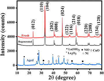 |
| | Fig. 4 Powder XRD patterns of as-prepared, aged, and regenerated Cu20LNO perovskite catalysts. | |
The aged and regenerated Cu20LNO catalysts possessed Scherer sizes of 13 and 23.4 nm, respectively. Thus, the increase in surface area (from 35 to 54 m2 g−1 on ageing) values from the BET measurement (discussed in Section 3.4) is well supported by the shrinkage of the size of the catalyst in the DRM reaction environment.
Structural refinement of the powder XRD patterns of the two phases was carried out to evaluate the structural identities of the pristine and regenerated phases. The FullProf Suite software was used to refine the XRD patterns. To properly index both the pristine and regenerated phase patterns during analysis, the rhombohedral (R![[3 with combining macron]](https://www.rsc.org/images/entities/char_0033_0304.gif) c) space group was needed. The absence of any signs of extra reflection in the refined patterns confirms their phase purity. Fig. 5 displays the refined patterns of the pristine and regenerated samples. The phase identities of the pristine and regenerated samples obtained by the refinement results are consistent with accounts in the literature. Table 2 provides the structural and refinement parameters for both phases. It is apparent that the peaks in the diffraction pattern of the regenerated phase of the catalyst are not as intense as in the pristine phase. This is merely due to the amount of sample used for diffraction, given that a smaller quantity of regenerated sample was used. This supports the structural congruity between the pristine and regenerated phases, as reported in our earlier article.50
c) space group was needed. The absence of any signs of extra reflection in the refined patterns confirms their phase purity. Fig. 5 displays the refined patterns of the pristine and regenerated samples. The phase identities of the pristine and regenerated samples obtained by the refinement results are consistent with accounts in the literature. Table 2 provides the structural and refinement parameters for both phases. It is apparent that the peaks in the diffraction pattern of the regenerated phase of the catalyst are not as intense as in the pristine phase. This is merely due to the amount of sample used for diffraction, given that a smaller quantity of regenerated sample was used. This supports the structural congruity between the pristine and regenerated phases, as reported in our earlier article.50
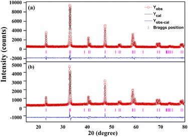 |
| | Fig. 5 Rietveld powder XRD patterns of (a) as-prepared and (b) regenerated Cu20LNO catalysts. The experimental data, computed pattern, difference curve, and Bragg position are represented by the open red circles, black lines, bottom blue lines, and vertical magenta bars, respectively. | |
Table 2 Structural and Rietveld refinement parameters of the Cu20LNO (LaNi0.8Cu0.2O3) perovskite catalyst material in the as-prepared and regenerated forms
| Catalyst |
Cell parameter |
Bond length (Å) |
Bond angle (°) |
Atomic coordinate |
| Cu20LNO |
a = 5.460 Å |
Ni/Cu–O: 1.943(9) |
Ni/Cu–O–Ni/Cu: 162.22 |
Atom |
x
|
y
|
z
|
| As-prepared |
b = 5.460 Å |
|
|
La |
0.00000 |
0.00000 |
0.25000 |
| Rhombohedral |
c = 13.167 Å |
|
|
Ni |
0.00000 |
0.00000 |
0.00000 |
|
Rc |
V = 339.98 Å3 |
|
|
Cu |
0.00000 |
0.00000 |
0.00000 |
|
|
γ = 120° |
|
|
O |
0.55500 |
0.00000 |
0.25000 |
|
|
R
Bragg = 3.32% |
|
|
|
|
|
|
|
|
R
f = 2.36% |
|
|
|
|
|
|
|
|
χ
2 = 2.75 |
|
|
|
|
|
|
|
|
| Cu20LNO |
a = 5.465 Å |
Ni/Cu–O: 1.944(0) |
Ni/Cu–O–Ni/Cu: 162.50 |
La |
0.00000 |
0.00000 |
0.25000 |
| Regenerated |
b = 5.465 Å |
|
|
Ni |
0.00000 |
0.00000 |
0.00000 |
| Rhombohedral |
c = 13.161 Å |
|
|
Cu |
0.00000 |
0.00000 |
0.00000 |
|
Rc |
V = 340.42 Å3 |
|
|
O |
0.55410 |
0.00000 |
0.25000 |
|
|
γ = 120° |
|
|
|
|
|
|
|
|
R
Bragg = 6.11% |
|
|
|
|
|
|
|
|
R
f = 3.39% |
|
|
|
|
|
|
|
|
χ
2 = 3.20 |
|
|
|
|
|
|
Subsequently, the regeneration of the catalyst was done in situ to further guarantee that the catalytic activity remained the same after its regeneration. Firstly, we performed the DRM test on the Cu20LNO sample for 10 h at 800 °C. After stopping the reaction, the gas lines were cleaned with helium (He) gas for 30 min. Then, the catalyst was regenerated at 800 °C (giving more importance to the synthesis temperature) for 3 h with zero air flow in place of the He gas flow. Fig. 6 presents the catalytic activity data of the as-prepared and regenerated Cu20LNO catalysts, suggesting the near complete retention of activity on regeneration. The activity test of the regenerated Cu20LNO was done using similar reaction conditions, where it must also be noted that regeneration at even lower temperatures of 600 °C and 700 °C resulted in similar activity (shown in Fig. 13), which is quite intriguing. Given that the H2/CO ratio of the as-prepared catalyst was greater than unity, it suggests the presence of the Boudouard reaction, which converts CO into carbon and carbon dioxide. Consequently, within the first 10 h of the reaction, the H2/CO ratio reached 1.5 and the overall amount of CO decreased. However, the H2/CO ratio progressively approached unity for the 100 h reaction.50 In the case of the regenerated catalyst, the H2/CO ratio varied from 1.3 to 1. In this case, the Boudouard reaction was predominant over the reverse water gas shift reaction (RWGS) during the initial hours. However, after ∼5 h of the commencement of the reaction, the H2/CO ratio reached close to unity, indicating the lower extent of both the side reactions (see Fig. 6).
 |
| | Fig. 6 (a) CH4 conversion, (b) CO2 conversion, and (c) H2/CO ratio of the as-prepared and in situ regenerated Cu20LNO catalyst materials for 10 h of DRM reaction (reaction conditions: CH4:CO2:He = 1:1:3.6, GHSV = 34000 mL gcat−1 h−1, 800 °C). | |
Thus, in the perovskite catalyst system further evaluated in this investigation, the intimate mixture at the molecular level of individual oxides and metallic nickel corresponding to the pristine perovskite phase is the actual performer in the observed DRM activity under the selected reaction conditions. We coined the terminology “molecular-level nanocomposite perovskite” catalyst for this intimate mixture of component phases. The molecular-level nanocomposite formed by the individual oxides together with metallic nickel is what we propose to be responsible for the observed high DRM activity behaviour. Under the chosen reaction conditions, this nanocomposite is the actual performer in the perovskite catalyst system in enhancing the DRM activity, while other oxides such as La2O3 act as a support30,32,48–50 and CuO promotes the DRM activity inside the reaction medium.49 The decomposition-regeneration process is reversible given that the aged catalyst phase can be restored to its pristine perovskite phase. A reforming atmosphere mediated the first phase, while a calcination step mediated the second phase.
3.4. BET surface area analyses
Fig. 7 displays the BET N2 adsorption–desorption isotherms of the as-prepared CuXLNO (where X = 10, 20, and 30) and aged and regenerated Cu20LNO materials and the corresponding inset contains their pore size distribution graphs. Table 3 includes the surface areas, pore volumes, and pore size distributions of the catalysts. The N2 gas adsorption–desorption isotherms of the as-prepared, aged, and regenerated Cu20LNO catalysts, which ranged from P/P0 values of 0 to 1, revealed that the amount of N2 gas adsorbed was lower at a low relative pressure and progressively increased at a high relative pressure, indicating the formation of a type IV isotherm with an H3-type hysteresis loop. The surface areas of the Cu10LNO, Cu20LNO, Cu30LNO, aged Cu20LNO, and regenerated Cu20LNO catalysts were determined to be approximately 26, 35, 31, 54, and 51 m2 g−1, respectively. Compared to all the other catalysts in the series, Cu20LNO possessed the maximum surface area, which contributes to its maximum DRM activity. After ageing in the reaction media, the surface area of the Cu20LNO catalyst increased to 54 m2 g−1 from 35 m2 g−1. This may be because the catalyst cracked down into its constituent oxide components and its particle size decreased to 13 nm, which was confirmed by additional XRD analysis. An increased surface area in the DRM atmosphere is crucial for improving methane conversion.
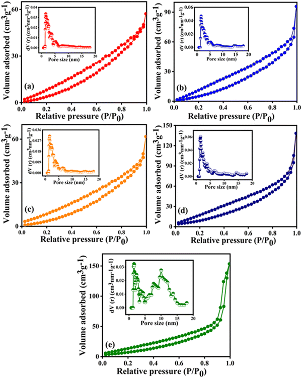 |
| | Fig. 7 N2 adsorption–desorption isotherms and pore size distribution curves (in the inset) of (a) Cu10LNO, (b) Cu20LNO, (c) Cu30LNO, (d) aged Cu20LNO, and (e) regenerated Cu20LNO. | |
Table 3 Textural characteristics of different CuXLNO (where X = 10, 20, and 30), aged and regenerated Cu20LNO catalysts with the production rates of H2 and CO per unit area (BET specific surface area) and per unit mass of the catalyst
| Catalyst |
Specific surface area (m2 g−1) |
Pore volume (cm3 g−1) |
Pore size (nm) |
Production rate of H2 × 103 |
Production rate of CO × 103 |
| (mol h−1 m−2 g) |
(mol h−1 g−1) |
(mol h−1 m−2 g) |
(mol h−1 g−1) |
| Cu10LNO |
26 |
0.073 |
1.58 |
0.195 |
50.7 |
0.189 |
49.3 |
| Cu20LNO |
35 |
0.101 |
1.58 |
0.152 |
53.5 |
0.146 |
51.5 |
| Cu30LNO |
31 |
0.071 |
1.58 |
0.165 |
51.3 |
0.163 |
50.4 |
| Aged Cu20LNO |
54 |
0.144 |
1.38 |
0.100 |
53.5 |
0.096 |
51.5 |
| Regenerated Cu20LNO |
51 |
0.139 |
1.36 |
0.104 |
53.5 |
0.100 |
51.5 |
The regenerated catalyst possessed an increased surface area of 51 m2 g−1. The high catalytic activity of this form of the catalyst is well-supported by its increased surface area in comparison to the as-prepared catalyst.
To gain better insight, the production rates of H2 and CO were calculated per unit area and per unit mass of catalyst (see Table 3). Based on the BET specific surface area, the aged Cu20LNO catalyst exhibited the lowest H2 and CO production rates of 0.100 × 10⁻³ and 0.096 × 10⁻³ mol h−1 m−2 g owing to its highest surface area (54 m2 g−1), respectively. In contrast, the Cu10LNO catalyst possessed the lowest surface area (26 m2 g−1) with the maximum H2 and CO production rates of 0.195 × 10⁻³ and 0.189 × 10⁻³ mol h−1 m−2 g, respectively. As discussed in the screening of the catalysts (Section 3.2), the Cu10LNO and Cu30LNO catalysts could convert a maximum of ∼93% methane, and hence were not considered further in the DRM tests. The conversion of methane at the experimental temperature of 800 °C was the same for the different forms of Cu20LNO, and the H2 and CO production rates were also similar with values of 53.5 × 10⁻³ and 51.5 × 10⁻³ mol h−1 g−1, respectively.
3.5. FESEM analyses
The surface morphologies and elemental contents of the as-prepared, aged, and regenerated catalysts were examined using FESEM microscopic analysis. According to the FESEM studies, it was observed that Cu20LNO existed as a highly aggregated combination of cubic, spherical, and hexagonal shaped nanoparticles, as presented in Fig. S1(a)–(d) (ESI†). The morphology of the aged Cu20LNO sample is shown in Fig. S1(g)–(j) (ESI†). The morphology of the aged catalyst was altered from its initial shape to a semi-spherical or rod shape, which may be the result of the catalyst decomposing or the catalyst sample being reduced in the reaction atmosphere. It should be noted that the aged sample contained some aggregated Cu20LNO, which had a spherical shape. The surface morphology of the regenerated Cu20LNO catalyst resembles that of the as-prepared catalyst, as shown in Fig. S1(k)–(n) (ESI†). The smooth surface of the catalyst was regained upon its regeneration. It was found that the regenerated Cu20LNO catalyst was a highly aggregated combination of nanoparticles with hexagonal, spherical, and cubic shapes based on the FESEM experiments. The EDX analysis of the as-prepared, aged, and regenerated Cu20LNO samples indicated the presence of La, Cu, Ni, and O elements, as shown in Fig. S1(e), (f) and (o) (ESI†). The as-prepared Cu20LNO catalyst material was observed to possess a smooth and transparent surface, whereas the smoothness of the aged sample decreased, which was probably because the catalyst was being reduced as it aged. It was observed that the smooth surface of the catalyst reappeared upon the regeneration of the aged catalyst.
3.6. HRTEM analyses
The microstructures of the as-prepared and aged Cu20LNO were examined by TEM and HRTEM investigations and the results are presented in Fig. 8. It can be observed from this figure that the as-prepared Cu20LNO has an uneven spherical and hexagonal morphology, as well as some cube-like particles according to Fig. 8(a), in contrast to its altered granular-like grouped asymmetrical sphere morphology, shown in Fig. 8(e), as it is aged in the DRM reaction medium. A lattice fringe (d spacing) of 0.272 nm, which corresponds to the (110) lattice plane of the Cu20LNO catalyst, can be seen in the HRTEM image (Fig. 8(c)) of the as-prepared Cu20LNO sample. The obtained data matches well with the XRD result of pure Cu20LNO. Alternatively, the (102) NiO lattice plane corresponds to the 0.23 nm lattice fringe and the 0.27 nm lattice fringe is attributed to the (002) lattice plane of La2O3 in the aged Cu20LNO sample, as displayed in Fig. 8(g). The XRD examination of the Cu20LNO sample obtained after the DRM reaction further supports this result, which shows that pure Cu20LNO transformed into various oxide phases following the DRM reaction. The selected area electron diffraction (SAED) pattern of the pure Cu20LNO catalyst is shown in Fig. 8(d) and the corresponding lattice planes of the aged Cu20LNO catalyst are indicated in its SAED pattern, as demonstrated in Fig. 8(h). No clear signature of carbon nanotubes is observed from the HRTEM analysis.
 |
| | Fig. 8 (a) and (e) TEM images, (b) and (f) HRTEM images, (c) and (g) zoomed portion of HRTEM images and (d) and (h) SAED patterns of as-prepared and aged Cu20LNO catalysts. | |
3.7. XPS analyses
To comprehend the components present and their oxidation states in the freshly prepared and aged Cu20LNO samples, XPS investigations were conducted and the results are presented in Fig. 9. The as-prepared, aged, and regenerated Cu20LNO catalysts contain La, C, O, and Cu according to the XPS survey spectra (not shown). The Ni 2p3/2 core level peak cannot be seen properly as it overlaps with the La 3d3/2 core level peaks. However, Ni 2p1/2 core level peak together with its satellite peak was observed in the survey spectra of all the catalysts.
 |
| | Fig. 9 XPS profiles of (a) La 3d + Ni 2p, (b) Cu 2p, (c) C 1s, and (d) O 1s core level regions of the different forms of the Cu20LNO catalyst. | |
The La 3d and Ni 2p core level spectra of the as-prepared, aged, and regenerated Cu20LNO were recorded simultaneously due to the overlap of their La 3d3/2 and Ni 2p3/2 core level regions, as shown in Fig. 9(a). A relatively strong peak at around 855 eV compared to the surrounding peaks is observed in the spectra of catalysts, which suggests the presence of Ni species in the La 3d core level area. The La 3d core level region of the as-prepared catalyst shows La 3d5/2,3/2 doublet peaks at 835.2 and 851.9 eV, respectively, which correspond to La(OH)3 species present in the catalyst. The observed significant tail peaks with considerable intensities at around 833.6 and 850.2 eV are attributed to La2O3. These values are in good agreement with the literature.51,52 These doublet peaks are associated with several initial and final states related to 3d94f1 (lower binding energy) and 3d94f0 (higher binding energy). The broad intense peak at around 855.0 eV is composed of both the La 3d3/2 3d94f0 final state of the La3+ species and Ni 2p3/2 of the Ni3+ species.51,53 The broad intense peak at 863.5 eV contains satellite peaks of Ni3+ and La3+. The peaks at 872.2 and 880.4 eV are attributed to Ni 2p1/2 of the Ni3+ species and related satellite, respectively. In the case of the aged catalyst, the nature of the La 3d + Ni 2p spectral region is slightly different from that of the pristine catalyst. The intense 3d5/2 peak at 835.4 eV signifies the existence of La(OH)3 species on its surface. There is a small tail peak at 833.9 eV related to La2O3. In the XRD pattern of the aged catalyst, the peak due to La(OH)3 is observed, which agrees well with the XPS observations of the aged catalyst.51,52 The decrease in the relative intensity of the peak at around 855 eV and low-deep valley at around 853.4 eV compared to that of the as-prepared catalyst indicates the presence of reduced Ni species such as Ni metal and Ni2+ on the surface of the aged catalyst formed during DRM reaction, which is consistent with the powder XRD findings (see Fig. 3). The La 3d core level spectrum of the regenerated catalyst looks similar to that of the as-prepared catalyst. However, the peaks related to La(OH)3 at 835.3 and 852.0 eV became prominent, which is due to the regeneration process of the catalyst. Fig. 9(b) displays the Cu 2p core level spectra of the as-prepared, aged, and regenerated catalyst, respectively. It contains a peak at 933.5 eV together with satellite peaks at 941.5 and 943.5 eV, indicating the presence of Cu2+ species.54–56 The satellite peaks are characteristics of transition metal oxides. There is no significant change in the Cu 2p spectral feature in the aged catalyst. However, the catalyst was regenerated, as evident from the corresponding Cu 2p core level spectrum of the regenerated catalyst. Further, the Cu2+ peaks are found to be intense and sharp compared to that of the as-prepared catalyst, which is attributed to the regeneration process of the catalyst, as observed in the La 3d + Ni 2p spectra. The C 1s core level spectra of the as-prepared, aged, and regenerated Cu20LNO catalysts indicate presence of different carbon species on the catalyst surface, as displayed in Fig. 9(c). Correspondingly, the core level peaks at 284.9, 286.2, and 289.1 eV are associated with C–C/C–H, C–O, and carbonate species (CO32−). The intensity of the C–O species gets increased at the cost of carbonate species in the aged catalyst. There is no significant change in the C 1s core level spectrum of the regenerated catalyst with respect to the as-prepared catalyst, confirming the regeneration of the catalyst.50 The O 1s core level spectra of the as-prepared and aged Cu20LNO catalysts are broad, whereas the regenerated catalyst shows a distinct peak in the low binding energy region, as presented in Fig. 9(d). The peaks observed at 528.6, 530.5, 531.7, 532.5, and 533.4 eV are associated with La–O, Cu–O, adsorbed hydroxyl (OH−), adsorbed carbonate, and adsorbed water species, respectively.57,58 In the regenerated catalyst, the presence of the intense and separated La–O peak is because of the regeneration process of the aged catalyst.
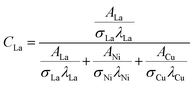
The relative surface concentrations of La, Ni, and Cu of the as-prepared, aged, and regenerated catalysts were estimated using the following relations:59
| |  | (11) |
| |  | (12) |
| |  | (13) |
where
C,
A,
σ, and
λ are the surface concentration, peak area, photoionization cross-section, and mean escape depth, respectively. The integrated areas of the La 3d
5/2, Ni 2p
1/2, and Cu 2p peaks were considered to estimate their concentrations, whereas the photoionization cross-sections and mean escape depths were obtained from the literature.
60,61 The relative surface concentrations (at%) of La, Ni and Cu in Cu20LNO are shown in
Table 4.
Table 4 Surface concentrations (at%) of La, Ni and Cu in the as-prepared, aged, and regenerated Cu20LNO catalysts
| Form of Cu20LNO catalyst |
Surface atomic concentration (at%) |
| La |
Ni |
Cu |
| As-prepared |
0.59 |
0.28 |
0.13 |
| Aged |
0.51 |
0.26 |
0.23 |
| Regenerated |
0.53 |
0.27 |
0.2 |
It is clear from this table that an increase in the Cu surface concentration and simultaneous decrease in the La and Ni surface concentrations were observed in the aged catalyst, indicating the segregation of Cu on the surface of the aged catalyst. However, the surface concentrations of La and Ni were found to increase in the regenerated catalyst.
3.8. Superiority of sol–gel method over ceramic and solution combustion methods
According to the foregoing findings, it is anticipated that any synthetic route leading to a nanocomposite of the requisite components of nanodimensions will show similar DRM behaviour. In this case, the question of the activity of a physical mixture of the catalyst arises. According to the stoichiometry of the Cu20LNO perovskite, can a finely mixed physical mixture (PM) of independently synthesised nanosized oxide components (Cu20LNO PM) exhibit the same activity as the in situ generated oxide nanocomposites? The catalyst composition was exactly the same as the nanocomposite that was generated in situ, and then subjected to a reforming environment above 450 °C, when metallic nickel, the missing component of the PM, is expected to be formed. The possibility of preparing a catalyst system corresponding to the perovskite composition by mixing the component oxides, and then comparing the activity of this physical mixture (Cu20LNO PM) with the sol–gel made catalyst was the second factor considered. The La2O3, CuO, and NiO oxides prepared via a similar sol–gel route50 were mixed thoroughly in a mortar and pestle for 3 h with the addition of acetone at intervals. To compare the activity of the physical mixture with that of the in situ produced catalyst during the first 10 h of the reforming reaction, one portion was employed immediately for the DRM process under similar reaction conditions. The other portion of the catalyst was calcined at 1200 °C for 3 h, as followed in the conventional ceramic method (CM). With a small quantity of NiO as an impurity, the desired perovskite phase was produced in this sample, named Cu20LNO CM, according to the XRD analysis (see Fig. 10(a)). The pure phase of the catalyst was also formed when synthesized via a one-step solution combustion method (see Fig. 10(b)).
 |
| | Fig. 10 Powder XRD patterns of Cu20LNO materials synthesized via (a) ceramic and (b) solution combustion methods. | |
The DRM activities were tested using the prepared catalysts with different compositions, namely Cu20LNO, Cu20LNO PM, Cu20LNO CM and Cu20LNO SCS, under the identical reaction conditions. It is interesting to note that the sol–gel method is superior to both the CM and SCS methods. In particular, the catalyst synthesized via the ceramic approach demonstrated ∼70% CH4 conversion and 89% CO2 conversion, with an H2/CO ratio of 1.3 during the 10 h of DRM reaction (see Fig. 11), which are much lower than that by the catalyst prepared using the sol–gel method. Nevertheless, this activity of perovskite prepared by the ceramic technique is rather remarkable and unavailable in the literature. The SCS-synthesized catalyst showed ∼65% CH4 conversion and ∼85% CO2 conversion with the H2/CO ratio of 1.3. Surprisingly, in the case of PM, almost no DRM activity was observed (data not included in the figure). After 10 h of DRM reaction, analysis of the powder XRD pattern of PM did not reveal any indication of metallic nickel. As a result, Ni0 was only formed during the decomposition of the perovskite phase, which must be present for the catalyst to exhibit DRM activity whether it is synthesized via the sol–gel method, traditional ceramic method or solution combustion. We already noted that the physical combination of the component phases had no beneficial effect on the DRM activity. Therefore, it is natural to conclude that Ni0 is only formed when the perovskite phase decomposes, which can happen via the sol–gel, traditional ceramic route, or solution combustion methods. This finding led us to conclude that the spatial distribution of the component phases is more significant than their simple presence in the catalyst matrix.
 |
| | Fig. 11 Activities of the Cu20LNO (synthesized via SG, CM, and SCS methods) catalyst materials for 10 h of DRM reaction: (a) CH4 conversion, (b) CO2 conversion and (c) H2/CO ratio (reaction conditions: 800 °C, CH4:CO2:He = 1:1:3.6, GHSV = 34000 mL gcat−1 h−1). | |
Table 5 presents a comparison of the Cu20LNO catalyst with similar types of catalysts available in the literature with respect to parameters such as methane and carbon dioxide conversion, H2/CO ratio, GHSV, temperature and duration of time on stream activity. Most of the durability tests were carried out at 800 °C or in a few cases at 750 °C. The Ni–Mo/MgO catalyst was found to be the best catalyst.47 Besides this catalyst, the DRM activity of the present LaNi0.8Cu0.2O3 catalyst is comparable to the Ni/MgO catalyst, although the GHSV was almost double in the latter case.46 The activity of the La(Co0.1Ni0.9)0.5Fe0.5O3 perovskite catalyst48 is also comparable to the Cu-doped perovskite catalyst in this study, but they merely tested their catalyst for 5 h. Thus, the catalytic activity data in Table 5 suggests the commendable activity behaviour of the present catalyst in the dry reforming of methane.
Table 5 Comparison of the DRM activity of the Cu20LNO catalyst with relevant catalysts reported in the literature
| Catalyst |
CH4 conversion (%) |
CO2 conversion (%) |
H2/CO ratio |
GHSV (mL gcat−1 h−1) |
Stability tested (h) |
Temperature (°C) |
Ref. |
| LaNi0.34Co0.33Mn0.33O3 |
92 |
96 |
1.20 |
12000 |
14 |
800 |
30
|
| LaNi0.6Mn0.4O3 |
50 |
85 |
1.10 |
15000 |
10 |
800 |
43
|
| LaNi0.8Fe0.2O3 |
50 |
40 |
0.80 |
15000 |
20 |
800 |
44
|
| LaNi0.2Mn0.8O3 |
77 |
84 |
1.10 |
15000 |
14 |
750 |
45
|
| Ni/MgO |
91 |
98 |
0.92 |
60000 |
120 |
800 |
46
|
| Ni–Mo/MgO |
75 |
80 |
0.86 |
60000 |
850 |
800 |
47
|
| La(Co0.1Ni0.9)0.5Fe0.5O3 |
70 |
80 |
0.92 |
36000 |
5 |
750 |
48
|
| LaNi0.8Cu0.2O3 |
73 |
90 |
0.84 |
— |
20 |
750 |
49
|
| LaNi0.8Cu0.2O3 |
97 |
99 |
1.4 to 0.9 |
34000 |
100 |
800 |
This work |
3.9. Insights into catalyst regeneration: effect of variation of the calcination temperature
It has already been noticed that the aged perovskite catalyst can be regenerated completely by calcination at the reaction temperature of 800 °C. The fact that all the characteristic diffraction peaks of the regenerated catalyst are at the same 2θ position as the fresh catalyst clearly indicates that it underwent complete phase regeneration (see Fig. 12). The XPS studies also demonstrated the similarity of the La 3d + Ni 2p, Cu 2p, C 1s, and O 1s core level spectra of the as-prepared catalysts with the regenerated catalyst. Therefore, these findings suggest that the catalyst can be applied in a cyclic fashion, and hence has promising potential application in the DRM reaction. Even more interesting, this catalyst could be successfully regenerated through calcination in air even at lower temperatures of 700 °C and 600 °C (with minor impurities of NiO, peak at 43.2°) for 3 h (see Fig. 12). The synthesis of the Cu20LNO CM catalyst via the ceramic route required a much higher temperature for phase formation, and hence the regeneration of the phase was achieved through calcination at the same temperature of 1200 °C (see Fig. 10(a)). However, for the regeneration of the SCS catalyst, the calcination temperature was chosen to be the lowest, namely 600 °C (see Fig. 10(b)), to maintain similarity with the sol–gel-made sample.
 |
| | Fig. 12 Powder XRD patterns of as-prepared and regenerated (at various temperatures) sol–gel-synthesized Cu20LNO catalyst. | |
Fig. 13 shows the DRM activity of the sol–gel-synthesized Cu20LNO catalyst regenerated at various calcination temperatures under the same reaction conditions. It is clearly evident that the catalyst forms regenerated at lower (than synthesis) temperatures of 700 °C and 600 °C show similar CH4 and CO2 conversion values and H2/CO ratios to the sample regenerated at 800 °C. Thus, the DRM activity was practically the same irrespective of the regeneration temperature. The regeneration temperatures did not compromise the catalytic activity except for a slight variation in the H2/CO ratio (see Fig. 13(a)–(c)). In ideal cases, the H2/CO ratio should be unity. This variation in H2/CO ratio occurs due to some side reactions, thermodynamically feasible at the reaction temperature, happening inside the reaction medium. The H2/CO ratio varied from 1.4 to 1.1 for the catalyst regenerated at 800 °C, preferably indicating the occurrence of the Boudouard reaction. The H2/CO ratio gradually reaching unity implies a gradual decrease in the Boudouard reaction in the DRM reaction medium. In the case of catalyst regenerated at 700 °C, the H2/CO ratio ranged from 0.9 to 1.1. This suggests that the reverse water gas shift reaction (RWGS) occurs slightly in the first stage. Moreover, the RWGS steadily reduced until the H2/CO ratio approached unity. The H2/CO ratio for the catalyst that underwent regeneration at 600 °C is in the range of 1.1 to 0.9 (see Fig. 13(c)), which is quite close to unity, suggesting a slight occurrence of both the Boudouard and RWGS reactions.
 |
| | Fig. 13 Catalytic activities of the Cu20LNO catalyst regenerated at various temperatures: (a) CH4 conversion, (b) CO2 conversion, and (c) H2/CO ratio. | |
3.10. TGA studies
The carbon deposition on the catalyst surface in the long run (100 h of DRM reaction) was assessed via thermogravimetric measurement of the aged form of Cu20LNO and compared with that of the pristine sample (see Fig. 14). With a gradual increase in the temperature to 900 °C, there was no loss of mass for the sample that was initially prepared. However, there were two instances of mass loss for the aged sample, with the smaller one starts occurring at 348 °C and the larger one starts occurring at 490 °C. The removal of carbon from the catalyst surface, most likely as CO2, accounts for about 34% mass loss.
 |
| | Fig. 14 TGA curves of the as-prepared and aged Cu20LNO catalysts. | |
The impact of carbon structure on the dry reforming activity and stability in the Ni–carbon composite catalysts over mesocellular silica (MS) synthesized using the catalytic chemical vapor deposition (CCVD) technique was investigated by Donphai et al.62 According to their reports, the temperature of CCVD synthesis has an important effect on both the activity and stability of the catalysts by affecting the amorphous carbon to CNT transition. The mass loss at 300–400 °C was ascribed to amorphous carbon, less stable CNTs at 400–540 °C, and very stable CNTs at 540–750 °C. However, in the Ni–CNT composite catalysts, the less stable CNTs and amorphous carbon partially enveloping the nickel clusters could be gasified or hydrogenated by methanation. Two instances of mass loss were reported by Xu et al.63 The oxidation of amorphous carbon is responsible for the peak at approximately ∼500 °C, while that of carbon nanotubes is responsible for the peak at approximately ∼640 °C. Therefore, amorphous carbon is formed more easily at lower temperatures, and finally transforms into graphite carbon at higher temperatures. It seems that the structure of the deposited coke has a greater influence than its content.64 Methane conversion is said to be slowed down when active types of catalyst particles are encased in carbon, both graphitic and amorphous carbon layers.65 The XRD and HRTEM examinations of the aged Cu20LNO catalyst in this study did not reveal any evidence of crystalline forms of carbon, likely indicating the amorphous nature of the coke produced. The TGA study indicated that the mass loss was completed at around 500 °C. This again supports the nature of the deposited coke to be amorphous.44,50 It is also plausible to believe that the carbon that form remained separate from the catalyst crystallites or particles and combined with them to produce the nanocomposite. Fig. 15 shows a schematic representation of one potential reversible in situ structural transition that could arise. Without substantially changing their initial positions within the perovskite structure, the starting perovskite Cu20LNO (left) decomposed to the component metal/metal oxides in situ in the reforming reaction (right), and subsequently positioned at the corresponding locations of the metal ions in the structure of the pristine perovskite. When heated in air at about 600 °C, the components can be easily switched back to their original perovskite structure due to their closeness (∼atomic dimension). Additionally, it seems that a structure like this will facilitate the easy removal of the deposited amorphous carbon species during calcination, leaving an unaltered catalyst surface. As a result, the DRM activity is the same in both phases. The consistent conversion behaviour over an extended period of 100 h also indicates synchronous Boudouard and reverse Boudouard processes.30–32 Although the former process results in the deposition of coke, the latter step also takes place simultaneously to facilitate the smooth functioning of the DRM process. The process of methanation and the RWGS reaction, which may not be totally ignored, is also indicated by the sustained DRM activity.16 Briefly, the Cu20LNO catalyst can be considered a nanocomposite at the molecular level, which is composed of the individual oxide components conforming to Cu20LNO and a definite portion of metallic Ni. Based on these findings, the observed high DRM activity behaviour is attributed to the individual oxides together with metallic nickel, forming a molecular-level nanocomposite, which are the actual performers in the perovskite catalyst system in enhancing the DRM activity under the chosen reaction conditions, where other oxides such as La2O3 act as a support and the presence of CuO promotes the activity inside the reaction medium. The active phase of the DRM, the ensuing Ni0/NiO nanocomposite, remains highly dispersed on the surface of La2O3.45 This simple La2O3 support is well-defined structure on which small metal particles, produced by in situ reduction in the DRM atmosphere, are uniformly distributed. Tiny metal particles help to inhibit the deposition of carbon, while enhancing the stability and activity of the catalyst. Coke formation may be inhibited via an alternative route. The carbonaceous species deposited on the Ni particles reacts at first with the supports to produce La2O2CO3–CuO in situ.45 This is subsequently decomposed to liberate CO2, thereby regenerating fresh La2O3 and re-establishing Ni activity towards CH4 reforming. This nanocomposite exhibited reversible thermal switching involving the parent perovskite and the nanocomposite, which accounts for the high DRM activity of the Cu20LNO catalyst.50
 |
| | Fig. 15 Diagram illustrating the reversible thermal switching (≥600 °C) between the pristine perovskite and the molecular-level nanocomposite of perovskite formed in situ during DRM. A schematic representation of amorphous carbon deposition on the nanocomposite is also provided. | |
4. Conclusions
In the current study, nano-sized Cu-doped LaNiO3 (LNO) catalysts were prepared using the conventional one-pot citric acid sol–gel method. The as-prepared catalysts adopted the rhombohedral phase, which was supported by the XRD analyses. The preliminary test of DRM was performed at 800 °C for 10 h. The most active Cu20LNO catalyst was used in the DRM reaction for a long period of 100 h at the same temperature with a feed ratio of 1:1:3.6 = CH4:CO2:He and GHSV = 34000 mL gcat−1 h−1. The individual oxides/metal, La2O3, Ni, NiO, CuO, and La(OH)3, were formed by the decomposition of the catalyst in the DRM reaction environment, as demonstrated by carefully analysing the Cu20LNO catalyst in both its as-prepared and aged forms employing several techniques. Smaller-sized individual metal oxides and metallic nickel on the sample surface are crucial for enhancing the catalyst activity in the DRM reaction medium. Other oxides such as La2O3 acted as a support and CuO promoted the activity inside the reaction medium, and the individual oxides together with metallic nickel formed a molecular-level nanocomposite, which were the actual performers in the perovskite catalyst system in enhancing the DRM activity under the selected reaction conditions. The as-prepared Cu20LNO sample possessed a specific surface area of 35 m2 g−1, whereas the aged Cu20LNO sample had a larger specific surface area of 54 m2 g−1, suggesting the formation of smaller components subsequent to phase decomposition. The higher specific surface area of 51 m2 g−1 of the regenerated Cu20LNO catalyst nicely supported the high DRM activity and reusability of this catalyst for the DRM reaction.
The apparent activation energy values showed that the aged Cu20LNO catalyst had the lowest energy barrier for H2 and CO production (66.7 and 37.3 kJ mol−1, respectively). Alternatively, pure LNO had the maximum apparent activation energy (105.5 and 72.7 kJ mol−1 for H2 and CO production, respectively). These data are also in good agreement with the highest activity of the aged, i.e., molecular-level nanocomposite, form of the Cu20LNO catalyst. The lost perovskite phase of the aged catalyst was restored by calcination of the aged sample at 800 °C for 3 h, although the aged sample was broken down into distinct individual oxides in the reaction environment. The XRD analyses clearly demonstrated that the characteristic peaks of the regenerated catalyst corresponding to the perovskite phase reappeared at the same 2θ positions of the as-prepared catalyst. More interestingly, the phase regeneration was shown to be possible even at the lowest calcination temperature of 600 °C. The findings from the XPS surface characterization are also consistent with the other data. Thus, the Cu-doped LaNiO3 perovskite catalyst, LaNi0.8Cu0.2O3, has robust DRM activity with potential for commercialization.
Data availability
All the data required to support the study are presented in the manuscript (figures and tables).
Conflicts of interest
The authors declare that there is no conflict of interest regarding the publication of this article.
Acknowledgements
Financial supports from the Science and Engineering Research Board (SERB), Government of India, by the grant EMR/2016/001811 to A. Gayen, CSIR research fellowship to A. Hossain, DST Special Grant in the International Year of Chemistry 2011 to the Department of Chemistry, Jadavpur University and the PURSE II Grant to Jadavpur University are gratefully acknowledged. J. L. is a Serra Húnter Fellow and is grateful to ICREA Academia program and projects MICINN/FEDER PID2021-124572OB-C31 and GC 2021 SGR 01061. M. Vasundhara would like to acknowledge the support offered by Department of K&IM of Indian Institute of Chemical Technology (IICT/Pubs./2024/353).
References
- A. Abdulrasheed, A. A. Jalil, Y. Gambo, M. Ibrahim, H. U. Hambali and M. Y. S. Hamid, A review on catalyst development for dry reforming of methane to syngas: recent advances, Renewable Sustainable Energy Rev., 2019, 108, 175–193, DOI:10.1016/j.rser.2019.03.054.
- M. Li and A. C. Veen, Coupled reforming of methane to syngas (2H2-CO) over Mg–Al oxide supported Ni catalyst, Appl. Catal., A, 2018, 550, 176–183, DOI:10.1016/j.apcata.2017.11.004.
- S. A. Arni, B. Bosio and E. Arato, Syngas from sugarcane pyrolysis: an experimental study for fuel cell applications, Renewable Energy, 2010, 35, 29–35, DOI:10.1016/j.renene.2009.07.005.
- C. C. Liu, S. S. Shy, C. W. Chiu, M. W. Peng and H. J. Chung, Hydrogen/carbon monoxide syngas burning rates measurements in high-pressure quiescent and turbulent environment, Int. J. Hydrogen Energy, 2011, 36, 8595–8603, DOI:10.1016/j.ijhydene.2011.04.087.
- S. You, Y. S. Ok, S. S. Chen, D. C. W. Tsang, E. E. Kwon, J. Lee and C. H. Wang, A critical review on sustainable biochar system through gasification: energy and environmental applications, Bioresour. Technol., 2017, 246, 242–253, DOI:10.1016/j.biortech.2017.06.177.
- X. H. Pham, U. P. M. Ashik, J. I. Hayashi, A. P. Alonso, D. Pla, M. Gomez and D. P. Minh, Review on the catalytic tri-reforming of methane – Part II: catalyst development, Appl. Catal., A, 2021, 623, 118286, DOI:10.1016/j.apcata.2021.118286.
- R. C. Canatoy, S. T. Jeong, S. J. C. Galgo, P. J. Kim and S. R. Cho, Biochar as soil amendment: syngas recycling system is essential to create positive carbon credit, Sci. Total Environ., 2022, 809, 151140, DOI:10.1016/j.scitotenv.2021.151140.
- S. Singh, R. Kumar, H. D. Setiabudi, S. Nanda and D. V. N. Vo, Advanced synthesis strategies of mesoporous SBA-15 supported catalysts for catalytic reforming applications: a state-of-the-art review, Appl. Catal., A, 2018, 559, 57–74, DOI:10.1016/j.apcata.2018.04.015.
- G. Chen, I. A. Jamro, S. R. Samo, T. Wenga, H. A. Baloch, B. Yan and W. Ma, Hydrogen-rich syngas production from municipal solid waste gasification through the application of central composite design: an optimization study, Int. J. Hydrogen Energy, 2020, 45, 33260–33273, DOI:10.1016/j.ijhydene.2020.09.118.
- A. C. V. Olivares, M. N. Barroso, C. A. Lopez, J. Llorca and M. C. Abello, Chelating agent effects in the synthesis of supported Ni nanoparticles as catalysts for hydrogen production, Appl. Catal., A, 2021, 622, 118219, DOI:10.1016/j.apcata.2021.118219.
- V. L. Parola, L. F. Liotta, G. Pantaleo, M. L. Testa and A. M. Venezia, CO2 reforming of CH4 over Ni supported on SiO2 modified by TiO2 and ZrO2: effect of the support synthesis procedure, Appl. Catal., A, 2022, 642, 118704, DOI:10.1016/j.apcata.2022.118704.
- P. Nikolaidis and A. Poullikkas, A comparative overview of hydrogen production processes, Renewable Sustainable Energy Rev., 2017, 67, 597–611, DOI:10.1016/j.rser.2016.09.044.
- Z. Ou, Z. Zhang, C. Qin, H. Xia, T. Deng, J. Niu, J. Ran and C. Wu, Highly active and stable Ni/perovskite catalysts in steam methane reforming for hydrogen production, Sustainable Energy Fuels, 2021, 5, 1845–1856, 10.1039/D1SE00082A.
- D. Luo, X. Liu, T. Chang, J. Bai, W. Guo, W. Zheng and X. Wen, Towards understanding the lower CH4 selectivity of HCP-Co than FCC-Co in Fischer–Tropsch synthesis, Phys. Chem. Chem. Phys., 2024, 26, 5704–5712, 10.1039/D3CP06041A.
- R. G. Santos and A. C. Alencar, Biomass-derived syngas production via gasification process and its catalytic conversion into fuels by Fischer Tropsch synthesis: a review, Int. J. Hydrogen Energy, 2020, 45, 18114–18132, DOI:10.1016/j.ijhydene.2019.07.133.
- L. Ma, B. Wang, M. Fan, L. Ling and R. Zhang, A specific defect type of Cu active site to suppress Water–Gas-Shift reaction in syngas conversion to methanol over Cu catalysts, Chem. Eng. Sci., 2023, 269, 118496, DOI:10.1016/j.ces.2023.118496.
- S. Asthana, K. Tripathi and K. K. Pant, Impact of La engineered stable phase mixed precursors on physico-chemical features of Cu-based catalysts for conversion of CO2 rich syngas to methanol, Catal. Today, 2022, 404, 154–168, DOI:10.1016/j.cattod.2022.02.013.
- P. Luo, Y. Liu, K. Wang, Z. Li, C. Zhang, Y. Wu, X. Zan and W. Huang, Investigation of Al precursor for ethanol synthesis from syngas on Cu-based multifunctional catalyst, Fuel Process. Technol., 2023, 245, 107728, DOI:10.1016/j.fuproc.2023.107728.
- M. Shahabuddin, G. Brooks and M. A. Rhamdhani, Decarbonisation and hydrogen integration of steel industries: recent development, challenges and technoeconomic analysis, J. Cleaner Prod., 2023, 395, 136391, DOI:10.1016/j.jclepro.2023.136391.
- H. Elsheikh and V. Eveloy, Assessment of variable solar- and grid electricity-driven power-to-hydrogen integration with direct iron ore reduction for low-carbon steel making, Fuel, 2022, 324, 124758, DOI:10.1016/j.fuel.2022.124758.
- I. N. Zaini, A. Nurdiawati, J. Gustavsson, W. Wei, H. Thunman, R. Gyllenram, P. Samuelsson and W. Yang, Decarbonising the iron and steel industries: production of carbon-negative direct reduced iron by using biosyngas, Energy Convers. Manage., 2023, 281, 116806, DOI:10.1016/j.enconman.2023.116806.
- L. A. Schulz, L. C. S. Kahle, K. H. Delgado, S. A. Schunk, A. Jentys, O. Deutschmann and J. A. Lercher, On the coke deposition in dry reforming of methane at elevated pressures, Appl. Catal., A, 2015, 504, 599–607, DOI:10.1016/j.apcata.2015.03.002.
- F. G. Denardin, A. R. Muniz and O. W. Perez-Lopez, Nature of the interactions between Fe and Zr for the methane dehydroaromatization reaction in ZSM-5, J. Mol. Struct., 2020, 1220, 128720, DOI:10.1016/j.molstruc.2020.128720.
- X. Li, Q. Hu, Y. Yang, Y. Wang and F. He, Studies on stability and coking resistance of Ni/BaTiO3–Al2O3 catalysts for lower temperature dry reforming of methane (LTDRM), Appl. Catal., A, 2012, 413–414, 163–169, DOI:10.1016/j.apcata.2011.11.004.
- N. Vosooghi, S. Askari, M. Rashidzadeh and S. Sadighi, Promotion of the acidity and textural properties of NiMo/γ-Al2O3 catalyst by applying fluorine, boron and phosphorus in hydrodesulfurization of diesel fuel, J. Mol. Struct., 2022, 1270, 133911, DOI:10.1016/j.molstruc.2022.133911.
- W. Liu, L. Li, S. Lin, Y. Luo, Z. Bao, Y. Mao, K. Li, D. Wu and H. Peng, Confined Ni-In intermetallic alloy nanocatalyst with excellent coking resistance for methane dry reforming, J. Energy Chem., 2022, 65, 34–47, DOI:10.1016/j.jechem.2021.05.017.
- W. Wattanathana, N. Nootsuwan, C. Veranitisagul, N. Koonsaeng, N. Laosiripojana and A. Laobuthee, Simple cerium-triethanolamine complex: synthesis, characterization, thermal decomposition and its application to prepare ceria support for platinum catalysts used in methane steam reforming, J. Mol. Struct., 2015, 1089, 9–15, DOI:10.1016/j.molstruc.2015.02.010.
- A. Abanades, E. Ruiz, E. M. Ferruelo, F. Hernandez, A. Cabanillas, J. M. M. Val, J. A. Rubio, C. Lopez, R. Gavela, G. Barrera, C. Rubbia, D. Salmieri, E. Rodilla and D. Gutierrez, Experimental analysis of direct thermal methane cracking, Int. J. Hydrogen Energy, 2011, 36, 12877–12886, DOI:10.1016/j.ijhydene.2011.07.081.
- M. Yousefi and S. Donne, Technical challenges for developing thermal methane cracking in small or medium scales to produce pure hydrogen –
A review, Int. J. Hydrogen Energy, 2022, 47, 699–727, DOI:10.1016/j.ijhydene.2021.10.100.
- W. Y. Kim, J. S. Jang, E. C. Ra, K. Y. Kim, E. H. Kim and J. S. Lee, Reduced perovskite LaNiO3 catalysts modified with Co and Mn for low coke formation in dry reforming of methane, Appl. Catal., A, 2019, 575, 198–203, DOI:10.1016/j.apcata.2019.02.029.
- D. Wang, P. Littlewood, T. J. Marks, P. C. Stair and E. Weitz, Coking can enhance product yields in the dry reforming of methane, ACS Catal., 2022, 12, 8352–8362, DOI:10.1021/acscatal.2c02045.
- S. Sun, Y. Zhang, C. Li, Y. Wang, C. Zhang, X. Zhao, H. Sun and C. Wu, Upgrading CO2 from simulated power plant flue gas via integrated CO2 capture and dry reforming of methane using Ni-CaO, Sep. Purif. Technol., 2023, 308, 122956, DOI:10.1016/j.seppur.2022.122956.
- Y. O. Sokefun, J. Trottier, M. M. Yung, B. Joseph and J. N. Kuhn, Low temperature dry reforming of methane using Ru–Ni–Mg/ceria-zirconia catalysts: effect of Ru loading and reduction temperature, Appl. Catal., A, 2022, 645, 118842, DOI:10.1016/j.apcata.2022.118842.
- I. Luisetto, C. Sarno, D. D. Felicis, F. Basoli, C. Battocchio, S. Tuti, S. Licoccia and E. D. Bartolomeo, Ni supported on γ-Al2O3 promoted by Ru for the dry reforming of methane in packed and monolithic reactors, Fuel Process. Technol., 2017, 158, 130–140, DOI:10.1016/j.fuproc.2016.12.015.
- P. F. Qu and G. C. Wang, Theoretical insight into the strong size-dependence of dry reforming of methane over Ru/CeO2, J. CO2 Util., 2022, 65, 102221, DOI:10.1016/j.jcou.2022.102221.
- D. G. Araiza, D. G. Arcos, A. G. Cortés and G. Díaz, Dry reforming of methane over Pt–Ni/CeO2 catalysts: effect of the metal composition on the stability, Catal. Today, 2021, 360, 46–54, DOI:10.1016/j.cattod.2019.06.018.
- M. Usman, W. M. A. W. Daud and H. F. Abbas, Dry reforming of methane: influence of process parameters—A review, Renewable Sustainable Energy Rev., 2015, 45, 710–744, DOI:10.1016/j.rser.2015.02.026.
- J. J. T. Herrera, S. A. Korili and A. Gil, Bimetallic (Pt–Ni) La-hexaaluminate catalysts obtained from aluminum saline slags for the dry reforming of methane, Chem. Eng. J., 2022, 433, 133191, DOI:10.1016/j.cej.2021.133191.
- D. J. Xu, J. Wu, Z. Liu, L. Y. Qiao, S. S. Zong, Z. F. Zhou and Y. G. Yao, Doping low amount of Zirconium in Rh-LTO to prepare durable catalysts for dry reforming of methane, Mol. Catal., 2023, 535, 112822, DOI:10.1016/j.mcat.2022.112822.
- V. A. Kondratenko, U. Karimova, A. A. Kasimov and E. V. Kondratenko, Methane conversion into synthesis gas over supported well-defined Pt, Rh or Ru nanoparticles: effects of metal and support, Appl. Catal., A, 2021, 619, 118143, DOI:10.1016/j.apcata.2021.118143.
- S. Katheria, G. Deo and D. Kunzru, Rh-Ni/MgAl2O4 catalyst for steam reforming of methane: effect of Rh doping, calcination temperature and its application on metal monoliths, Appl. Catal., A, 2019, 570, 308–318, DOI:10.1016/j.apcata.2018.11.021.
- N. E. McGuire, N. P. Sullivan, O. Deutschmann, H. Zhu and R. J. Kee, Dry reforming of methane in a stagnation-flow reactor using Rh supported on strontium-substituted hexaaluminate, Appl. Catal., A, 2011, 394, 257–265, DOI:10.1016/j.apcata.2011.01.009.
- A. Shahnazi and S. Firoozi, Improving the catalytic performance of LaNiO3 perovskite by manganese substitution via ultrasonic spray pyrolysis for dry reforming of methane, J. CO2 Util., 2021, 45, 101455, DOI:10.1016/j.jcou.2021.101455.
- A. Jahangiri, H. Aghabozorg and H. Pahlavanzadeh, Effects of Fe substitutions by Ni in La–Ni–O perovskite-type oxides in reforming of methane with CO2 and O2, Int. J. Hydrogen Energy, 2013, 38, 10407–10416, DOI:10.1016/j.ijhydene.2013.05.080.
- G. Valderrama, A. Kiennemann, C. U. Navarro and M. R. Goldwasser, LaNi1−xMnxO3 perovskite-type oxides as catalysts precursors for dry reforming of methane, Appl. Catal., A, 2018, 565, 26–33, DOI:10.1016/j.apcata.2018.07.039.
- Y. H. Hu and E. Ruckenstein, Comment on “Dry reforming of methane by stable Ni–Mo nanocatalysts on single-crystalline MgO”, Science, 2020, 368, 6492, DOI:10.1126/science.abb5459.
- Y. Song, E. Ozdemir, S. Ramesh, A. Adishev, S. Subramanian, A. Harale, M. Albuali, B. A. Fadhel, A. Jamal, D. Moon, S. H. Choi and C. T. Yavuz, Dry reforming of methane by stable Ni–Mo nanocatalysts on single-crystalline MgO, Science, 2020, 367, 777–781, DOI:10.1126/science.aav2412.
- H. Wang, X. Dong, T. Zhao, H. Yu and M. Li, Dry reforming of methane over bimetallic Ni-Co catalyst prepared from La(CoxNi1−x)0.5Fe0.5O3 perovskite precursor: catalytic activity and coking resistance, Appl. Catal., B, 2019, 245, 302–313, DOI:10.1016/j.apcatb.2018.12.072.
- G. R. Moradi, F. Khosravian and M. Rahmanzadeh, Effects of partial substitution of Ni by Cu in LaNiO3 perovskite catalyst for dry methane reforming, Chin. J. Catal., 2012, 33, 797–801, DOI:10.1016/S1872-2067(11)60378-1.
- A. Hossain, M. Bhattacharjee, K. Ghorai, J. Llorca, M. Vasundhara, S. Roy, P. Bera, Md. M. Seikh and A. Gayen, High activity in dry reforming of methane by thermally switchable double perovskite and in situ generated molecular level nanocomposite, Phys. Chem. Chem. Phys., 2024, 26, 5447–5465, 10.1039/D3CP05494B.
- S. Mickevicius, S. Grebinskij, V. Bondarenka, B. Vengalis, K. Sliuzien, B. A. Orlowski, V. Osinniy and W. Drube, Investigation of epitaxial LaNiO3−x thin films by high-energy XPS, J. Alloys Compd., 2006, 423, 107–111, DOI:10.1016/j.jallcom.2005.12.038.
- V. Celorrio, E. Dann, L. Calvillo, D. J. Morgan, S. R. Hall and D. J. Fermin, Oxygen reduction at carbon-supported lanthanides: the role of the B-site, ChemElectroChem, 2016, 3, 283–291, DOI:10.1002/celc.201500440.
- S. Viswanathan, L. Mohan, S. John, P. Bera and C. Anandan, Effect of surface finishing on the formation of nanostructure and corrosion behavior of Ni–Ti alloy, Surf. Interface Anal., 2017, 49, 450–456, DOI:10.1002/sia.6178.
- T. Baidya, T. Mazumder, K. Y. Koltunov, P. R. Likhar, A. H. Clark, K. Tiwari, V. I. Sobolev, S. Payra, T. Murayama, M. Lin, P. Bera, S. Roy, K. Biswas, O. Safonova, B. S. Rao and M. Haruta, Low-temperature propylene epoxidation activity of CuO–CeO2 catalyst with CO + O2: role of metal–support interaction on the reducibility and catalytic property of CuOx Species, J. Phys. Chem. C, 2020, 124, 14131–14146, DOI:10.1021/acs.jpcc.0c00777.
- S. Maiti, A. K. Kundu, O. I. Lebedev, P. Bera, C. Anandan, A. Gayen and Md. M. Seikh, Synthesis and magnetic properties of nano-dimensional Fe1−xCuxAl2O4 (0.3 ≤ x ≤ 0.8), RSC Adv., 2015, 5, 83809–83817, 10.1039/C5RA14623B.
- S. Malwadkar, P. Bera and C. V. V. Satyanarayana, Influence of cobalt on performance of Cu–CeO2 catalysts for preferential oxidation of CO, J. Rare Earths, 2020, 38, 941–950, DOI:10.1016/j.jre.2019.08.001.
- K. Ghorai, A. Panda, A. Hossain, M. Bhattacharjee, M. Chakraborty, S. K. Bhattacharya, B. Show, A. Sarkar, P. Bera, H. Kim, Md. M. Seikh and A. Gayen, LaNiO3/g-C3N4 nanocomposite: an efficient Z-scheme photocatalyst for wastewater treatment using direct sunlight, J. Rare Earths, 2022, 40, 725–736, DOI:10.1016/j.jre.2021.04.013.
- S. D. Senanayake, D. Stacchiola, P. Liu, C. B. Mullins, J. Hrbek and J. A. Rodriguez, Interaction of CO with OH on Au(111): HCOO, CO3, and HOCO as key intermediates in the water-gas shift reaction, J. Phys. Chem. C, 2009, 113, 19536–19544, DOI:10.1021/jp908169s.
- C. J. Powell and P. E. Larson, Quantitative surface analysis by X-ray photoelectron spectroscopy, Appl. Surf. Sci., 1978, 1, 186–201, DOI:10.1016/0378-5963(78)90014-4.
- J. H. Scofield, Hartree-Slater subshell photoionization cross-sections at 1254 and 1487 eV, J. Electron Spectrosc. Relat. Phenom., 1976, 8, 129–137, DOI:10.1016/0368-2048(76)80015-1.
- D. R. Penn, Quantitative chemical analysis by ESCA, J. Electron Spectrosc. Relat. Phenom., 1976, 9, 29–40, DOI:10.1016/0368-2048(76)85004-9.
- W. Donphai, T. Witoon, K. Faungnawakij and M. Chareonpanich, Carbon-structure affecting catalytic carbon dioxide reforming of methane reaction over Ni–carbon composites, J. CO2 Util., 2016, 16, 245–256, DOI:10.1016/j.jcou.2016.07.011.
- D. Xu, Y. Xiong, S. Zhang and Y. Su, The synergistic mechanism between coke depositions and gas for H2 production from co-pyrolysis of biomass and plastic wastes via char supported catalyst, J. Waste Manage., 2021, 121, 23–32, DOI:10.1016/j.wasman.2020.11.044.
- A. J. Carrillo and J. M. Serra, Exploring the stability of Fe–Ni alloy nanoparticles exsolved from double-layered perovskites for dry reforming of methane, Catalysts, 2021, 11, 741, DOI:10.3390/catal11060741.
- O. U. Osazuwa, H. D. Setiabudi, R. A. Rasid and C. K. Cheng, Syngas production via methane dry reforming: a novel application of SmCoO3 perovskite catalyst, J. Nat. Gas Sci. Eng., 2017, 37, 435–448, DOI:10.1016/j.jngse.2016.11.060.
|
| This journal is © the Owner Societies 2024 |
Click here to see how this site uses Cookies. View our privacy policy here. 
 a,
Trilochan
Bhunia
a,
Jordi
Llorca
a,
Trilochan
Bhunia
a,
Jordi
Llorca


 for each ion current value. The reproducibility of the experimental data was verified, which suggested the experimental error was within ±3%. It should be mentioned that there was no need to rectify the m/z = 28 amu signal for CO2 cracking or the CH4 cracking contribution to the production of H2.


