
In-depth exploration of catalytic sites on amorphous solid water: I. The astrosynthesis of aminomethanol†
Giulia M.
Bovolenta
 ab,
Gabriela
Silva-Vera
a,
Stefano
Bovino
cde,
German
Molpeceres
f,
Johannes
Kästner
g and
Stefan
Vogt-Geisse
*a
ab,
Gabriela
Silva-Vera
a,
Stefano
Bovino
cde,
German
Molpeceres
f,
Johannes
Kästner
g and
Stefan
Vogt-Geisse
*a
aDepartamento de Físico-Química, Facultad de Ciencias Químicas, Universidad de Concepción, Concepción, Chile. E-mail: stvogtgeisse@qcmmlab.com
bAtomistic Simulations, Italian Institute of Technology, 16152 Genova, Italy
cChemistry Department, Sapienza University of Rome, P.le A. Moro, 00185 Rome, Italy
dINAF – Osservatorio Astrofisico di Arcetri, Largo E. Fermi 5, 50125 Firenze, Italy
eDepartamento de Astronomía, Facultad de Ciencias Físicas y Matemáticas, Universidad de Concepción, Av. Esteban Iturra s/n Barrio Universitario, Concepción, Chile
fDepartamento de Astrofísica Molecular Instituto de Física Fundamental (IFF-CSIC), Madrid, Spain
gInstitute for Theoretical Chemistry, University of Stuttgart, Pfaffenwaldring 55, 70569 Stuttgart, Germany
First published on 21st June 2024
Abstract
Chemical processes taking place on ice-grain mantles are pivotal to the complex chemistry of interstellar environments. In this study, we conducted a comprehensive analysis of the catalytic effects of an amorphous solid water (ASW) surface on the reaction between ammonia (NH3) and formaldehyde (H2CO) to form aminomethanol (NH2CH2OH) using density functional theory. We identified potential catalytic sites based on the binding energy distribution of NH3 and H2CO reactants, on a set-of-clusters surface model composed of 22 water molecules and found a total of 14 reaction paths. Our results indicate that the catalytic sites can be categorized into four groups, depending on the interactions of the carbonyl oxygen and the amino group with the ice surface in the reactant complex. A detailed analysis of the reaction mechanism using Intrinsic Reaction Coordinate and reaction force analysis, revealed three distinct chemical events for this reaction: formation of the C–N bond, breaking of the N–H bond, and formation of the O–H hydroxyl bond. Depending on the type of catalytic site, these events can occur within a single, concerted, albeit asynchronous, step, or can be isolated in a step-wise mechanism, with the lowest overall transition state energy observed at 1.3 kcal mol−1. A key requirement for the low-energy mechanism is the presence of a pair of dangling OH bonds on the surface, found at 5% of the potential catalytic sites on an ASW porous surface.
1 Introduction
In molecular clouds of the interstellar medium, where temperatures are extremely low (<20 K), interstellar dust grains are covered by thick ice mantles, which are significant reservoirs of chemical species. Recently, thanks to the extraordinary sensitivity offered by the James Webb Space Telescope (JWST), it has been possible to carry out ice observations with unprecedented resolution.1 In terms of composition,2,3 water is known to be the primary ice component, along with CO, NH3, CO2 and CH4. Although precise information about ice morphology is still lacking, water is assumed to be in the so-called amorphous solid water phase (ASW), and to feature a certain porosity.4 Experiments on ASW show5–7 that, due to the amorphous nature of the surface, molecules interact with ice in different ways depending on the type of sites. The strength of the interaction can be described by the binding energy (BE) of the molecule with respect to the ice surface. Therefore, every surface chemical process may depend on the adsorption profile of the participant molecules, which is characterized by the distribution of binding energies, although a specific connection between binding energies and catalytic activity is still missing. According to experimental8,9 and theoretical10 findings, these BE distributions resemble a Gaussian function. In a novel multi-binding approach, the single BE value for a certain species can be replaced with a BE Gaussian distribution, as it has been recently implemented11 in astrochemical kinetic models.Few theoretical studies have explored the impact of the surface morphology on interstellar reactive processes12 studied the hydrogenation of HCNO using QM/MM techniques on a hemispherical water surface with a radius of 34 Å and obtained 81 binding sites. They employed BHLYP-D3/def2-TZVPD in the QM region on five different H2CO adsorption sites with different BE and found no significant impact on the transition state energies. In a more recent work, paiva et al.13 studied the addition reaction of H2CO and HCO on 10 different periodic slabs, containing 25 water molecules randomly arranged within the unit cell. They found a significant catalytic effect of the water surface with respect to the gas phase reflected by a 50% reduction in the reaction barrier.
A good target for applying the multi-binding approach, to evaluate the catalytic effect of the plethora of possible binding sites present on an ASW surface, is the first step of the Strecker synthesis. This series of reactions has enjoyed a longstanding fascination in the astrochemical community, as it provides a pathway to the formation of glycine, the simplest amino acid, from relatively abundant species in the interstellar medium: NH3, H2CO and HCN. The first step corresponds to the nucleophilic addition of NH3 to H2CO to form NH2CH2OH (aminomethanol, AMeOH).
| H2CO + NH3 → NH2CH2OH | (1) |
Laboratory preparation and isolation of AMeOH have been elusive. The species has been tentatively formed in a seminal experimental work14 using ice-analogs, using a 10 K mixture of H2O:NH3:H2CO, co-deposited on a cold surface and subsequently warmed up, but the identification of the reaction product was considered ambiguous. The experiment has been repeated by Bossa et al.,15 confirming the previous findings and estimating AMeOH formation to take place between 80 and 100 K. Furthermore, AMeOH has also been identified in a temperature-programmed desorption experiment, starting from CH3NH2 and O2 ices, upon exposure to energetic electrons,16 showing unexpected kinetic stability under extreme environments. Nevertheless, AMeOH has hitherto not been observed in the interstellar medium.
The formation of AMeOH via the first step of the Strecker synthesis has also been studied theoretically. The gas phase barrier of this reaction has been determined to be high for interstellar conditions, amounting to 34 kcal mol−1.17 The water-catalyzed reaction has been studied in the presence of small water clusters17–19 and with the addition of implicit solvation using a polarizable continuum model. The incorporation of the water cluster results in a significant lowering of the reaction barrier by 20 kcal mol−1. To date, the most accurate barrier for the reaction in the presence of a water dimer, was provided by Courmier et al.18 at CCSD(T)/6-311+G**//MP2/6-311+G** level of theory, amounting to 14 kcal mol−1. Finally, the same reaction has been studied using larger cluster models. Rimola et al.20 simulated the reaction on a 18-molecules crystalline water ice surface model at DFT/B3LYP level, with a reported TS energy of 9.6 kcal mol−1.
In this work, we present a detailed analysis of the surface catalytic effect by studying the addition reaction of NH3 and H2CO on different catalytic sites of an ASW surface, spanned by a set of amorphized 22-water-molecules clusters. We also study the same reaction inside a nano-pore, derived from a periodic ASW surface of 500 water molecules. We explore the different reaction pathways by means of DFT and analyze the reaction mechanism using intrinsic reaction coordinate (IRC) energy profiles, natural bond orbital (NBO) bond order derivatives, and reaction force analysis. In Section 2, we describe the aspects of the methodology used in this work. In Section 3.1, we present the BE profiles of NH3 and H2CO, followed by the reaction path and potential energy surface (PES) analysis of the reaction in different binding scenarios, on the ASW set of clusters (Sections 3.2 and 3.3), and in a nano-pore model (Section 3.4). Finally, we discuss the results and the astrophysical implications in Section 4.
2 Theoretical methods
2.1 DFT model chemistry
We performed an extensive benchmark of DFT methods. The reference system for reaction (1) is constituted by the reactants coordinated to two water molecules (NH3 + H2CO + 2H2O), acting as proton transfer intermediaries during the reaction, in an arrangement commonly named as proton relay. The reference system geometry is DF-CCSD(T)-F12/cc-pVDZ-F12,21,22 which has been shown to provide excellent geometries.23 The energies of stationary points have been computed at CCSD(T)24 using a complete basis set (CBS) extrapolation.25,26 For the CBS extraploation we employed the aug-cc-pVXZ with X = D, T, Q for SCF energies, X = T, Q for MP2 correlation energies and X = D, T for CCSD and CCSD(T) correlation energies extrapolation using the extrapolation routines implemented in the Psi4 driver.27 We took into account around 53 DFT functionals for the geometry benchmark belonging to different classes, and two different basis sets: def2-SVP and def2-TZVP.28 This is due to the fact that a double ζ basis is used to study the reaction on a variety of binding sites on the larger surfaces, hence the need to assess the consistency of a specific DFT functional with the two tiers of method and basis. Dispersion effects are treated using D3BJ29,30 and D431 correction. The geometry benchmark has been carried out using Orca32 software, adopting TIGHTOPT thresholds criteria. The best method for the lower tier equilibrium geometry is BHandHLYP-D4/def2-SVP,33 with an average Root Mean Square Deviation (RMSD) error of 0.1 Å with respect to the CCSD(T) reference. Regarding the energy benchmark, 258 DFT functionals are considered. The best ones are BMK/def2-TZVP34 and ω-B97M-D3BJ/def2-TZVP (a modified version of ω-B97M-V augmented with D3BJ correction35) that show a mean absolute error (MAE) below 1 kcal mol−1.To summarize, the benchmark allows to identify two suitable methods: Tier 1: ω-B97M-D3BJ/def2-TZVP//BHandHLYP-D4/def2-SVP and Tier 2: BMK/def2-TZVP//BHandHLYP-D3BJ/def2-SVP. We used the former with the Orca software, and the latter with Gaussian36 software, due to the unavailability of Tier 1. For all calculations of the reactive sites on the ASW clusters we used the default optimization thresholds. Full benchmark results can be found in the ESI† (Section S1). High level CCSD(T)-F12 optimizations are performed using Molpro.37
2.2 ASW modeling
 | ||
| Fig. 1 (a) Some of the 20 homogeneous 22-water-molecules amorphous clusters used in this work for BE evaluation and reactivity studies. After modeling through AIMD techniques, the structures undergo geometry optimization. (b) Generation of the nano-pore model. From the left: Altitude map (see ESI,† Section S6.2) of an ASW slab composed of 500 water molecules, with an initial density of 0.8 g cm−3 and top view of the corresponding periodic cell. One of the suitable nano-porous regions of the slab is highlighted in yellow. To the right: The spherical pore site as extracted from the slab, prior to geometry optimization. The color scheme for the atoms is red for O and white for H. | ||
To run MD simulations on the periodic systems, the GMNN program44 is interfaced to the ASE package.47 Orca32 software is used to compute DFT energies and gradients that constitute MLP training set.
2.3 Binding energy, binding energy distributions, interaction energy
The BE of a species (i) adsorbed on a surface (ice) is defined as:| BE(i) = Esup − (Eice + Ei) | (2) |
• Low-BE(i): BE < 0.2 × mean(BEd)
• High-BE(i): BE > 0.7 × mean(BEd)
The BE can be further decomposed into two components: the deformation energy DE(i) and interaction energy IE(i), such that BE(i) = DE(i) − IE(i). We computed the interaction energy using a zeroth order symmetry adapted perturbation theory (SAPT0) analysis,50 together with a jun-cc-pVDZ51 basis set. This allowed us to directly quantify the strength of the non-covalent intermolecular interaction between the reactant complex (R) and the ASW surface (W) in the bound configuration:
| IE(R) = −IE(NH3 + H2CO⋯W) | (3) |
Binding sites optimization and BE computations are performed using Psi427via the platform BEEP.48,52 All SAPT0 computations use the density-fitted implementation53,54 provided in Psi4.
2.4 Reactive sites sampling
In agreement with the multi-binding framework, the reactions under study have been carried out on a variety of sites on the ASW surfaces. The procedure to obtain the set of transition states for reaction (1) has been the following:(1) Selection of several suitable Low-BE and High-BE binding sites for each reactant. The selection is based on the binding mode analysis which allows to identify the arrangement for the reaction to take place (vide infra, Section 3.1)
(2) Extensive sampling of the first fragment around the other in Low-BE and High-BE sites, and vice versa. This step provides a set of potential reaction sites.
(3) Transition state (TS) search and characterization for the whole set, exploring the PES by means of relaxed scan and nudged elastic band methods.55
The minimum energy structures are identified and optimized using Orca.
2.5 Reaction force analysis
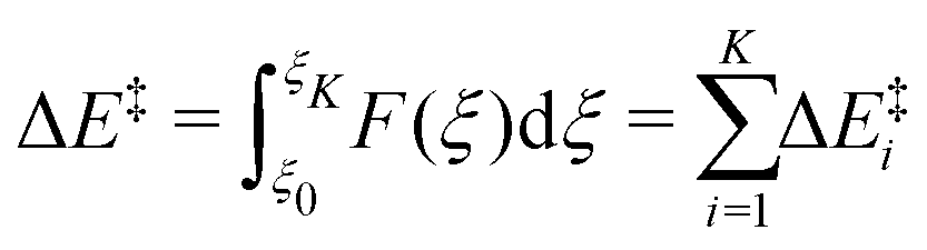
The most widespread method to locate a reaction path is tracing the IRC,56 which corresponds to the minimum energy path in mass-weighted coordinates. Useful information about the mechanism of a chemical process can be obtained from the reaction force profile. For a certain process, the potential energy E(ξ) of the system along the intrinsic reaction coordinate (ξ) has an associated reaction force F(ξ), defined by: | (4) |
It has been shown57 that the critical points of F(ξ) define regions along ξ in which different reactive events take place. The reactive events are identified as inflection points of the reaction force profile. Within each reaction event i, it is possible to identify three regions, limited within the critical points present in F(ξ), namely the local minimum, at ξmin,i, and the local maximum, at ξmax,i. The pre- and post-event region (ξ ≤ ξmin, ξmax ≤ ξ) are characterized by structural preparation and relaxation of the participating species, respectively. On the other hand, the event region itself is governed by changes in the electron density associated with bond formation and dissociation processes.
In general, a single kinetic step of a chemical reaction can be composed of N different reaction events, such that the total reaction energy corresponds to the sum of the energy of the individual reactive events:
 | (5) |
 | (6) |
 | (7) |
IRC calculations are performed with Gaussian36 after re-optimization of the stationary states with that same software. Analysis of the IRC profiles is carried out using Kudi.59 Natural atomic orbital (NAO) population analysis uses the NBO software version60 implemented in Gaussian and Orca.
3 Results
Fig. 2 shows the reactants, transition state, and product of reaction (1), studied on a two-water molecules cluster using high-level model chemistry (see Section 2.1). Overall, two new bonds are formed (C–N and O–H) and one bond is broken (N–H) to yield the AMeOH product. The reactive events involving the proton transfer are assisted by the two water molecules that relay the proton from the amino end to form the hydroxyl moiety in the amino alcohol. On this minimal water surface model, the reaction is exothermic by −9.3 kcal mol−1 with a TS barrier of 9.5 kcal mol−1. Fig. 2 also reports the two Tiers corresponding to the best performing methods of the TS and reaction energy benchmark, which shows an excellent agreement between the DFT model chemistry and the ab initio reference (see Section 2). | ||
| Fig. 2 Energy diagram for reaction (1), reference system (NH3 + H2CO + 2H2O), using CCSD(T)/CBS//DF-CCSD(T)-F12/cc-pVDZ-F12 level of theory (solid black line), ω-B97M-D3BJ/def2-TZVP//BHandHLYP-D4/def2-SVP (blue solid line, Tier 1) and BMK/def2-TZVP//BHandHLYP-D3BJ/def2-SVP (orange solid line, Tier 2) levels of theory. Water-OH groups not engaged in any H-bond with other water molecules are labelled d(OH) (dangling-OH bonds). The color scheme for the atoms is red for O, black for C, blue for N, and white for H. | ||
3.1 Binding modes and energies of NH3 and H2CO
With the goal of analyzing the binding patterns of NH3 and H2CO to the ASW surface that enable the formation of AMeOH, we analyzed the binding modes within the BE distribution that we obtained from the BEEP database, on a set of 22-water-molecules clusters. For reaction (1) to take place, NH3 has to be acting as a hydrogen-bond (H-bond) donor with respect to the ice, while carbonyl-O of H2CO is placed as H-bond acceptor. The surface molecule acting as a donor to the carbonyl-O presents an OH group pointing upwards away from the surface (not engaged in any other H-bond). Such surface OH bonds are labeled dangling-OH bonds – d(OH).Fig. 3 reports the BE distributions for both molecules. The fraction of binding sites compatible with reaction (1) has been highlighted in green, and represents the 48% and 83% for NH3 and H2CO, respectively. Among the binding sites, we identified different binding regimes: low-BE sites of NH3 and H2CO, in which there is only one ice H-bond acceptor and donor group, respectively, and High-BE sites, where there are two water molecules coordinated to each fragment. The latter corresponds to the interaction with two acceptor groups – High-BE(NH3)- and to two d(OH) bonds – High-BE(H2CO). Combining those possible binding regimes results in four limiting patterns for the reactants in the bound configuration (Fig. 4):
 | ||
| Fig. 3 Histogram of the BE distribution of H2CO (upper panel) and NH3 (lower panel) computed on a set-of-clusters model with a cluster size of 22 water molecules, using HF-3c/MINIX geometries. According to the benchmark results, the energy has been computed at ω-PBE/def2-TZVP level of theory for NH3 and CAM-B3LYP/def2-TZVP level of theory for H2CO. The ZPVE correction has not been included. BE values are given in K (upper scale) and kcal mol−1 (lower scale). The green color corresponds to the binding mode that is conducive to the formation of AMeOH through reaction (1), while binding modes that could not directly engage in a reactive encounter are in grey. Mean BE (μ) and standard deviation (σ) of a Gaussian fit of the distribution are reported in kcal mol−1 for the suitable binding mode (green). The fit is obtained using a bootstrap method, see ESI,† Section S6.1. The insets show an example of High-BE and Low-BE molecules in a favorable orientation for the reaction. Water-OH groups pointing upwards away from the surface (not engaged in any other H-bond) are labelled d(OH) (dangling-OH bonds). The color scheme for the atoms is red for O, black for C, blue for N, and white for H. | ||
 | ||
| Fig. 4 Example of structures belonging to the four groups of reactive sites identified for reaction (1), using BHandDHLYP-D4/def2-SVP geometries. The color scheme for the atoms is red for O, black for C, blue for N, and white for H. H-bonds established by the reactants have been highlighted and colored accordingly. | ||
• Low-BE(NH3)/Low-BE(H2CO)
• High-BE(NH3)/Low-BE(H2CO)
• Low-BE(NH3)/High-BE(H2CO)
• High-BE(NH3)/High-BE(H2CO)
3.2 Binding site sampling
We sampled selected binding sites representing the different binding regimes shown in the previous section, with its complementary reactant molecule for reaction (1), following the procedure illustrated in Section 2.4. In total, we identified 14 reaction-conducing catalytic sites on different ASW clusters, traceable to the aforementioned 4 categories. In order to further characterize and quantify the strength of the interaction of the reactant complex, we computed the IE(R) with respect to the ASW surface (eqn (3)), for the different reactive sites. The results are reported in Table 1. There is a good agreement between the binding regime of the individual reactants and the total IE(R), as the reactant complexes that correspond to High-BE orientations display the highest IE(R), while the ones that are categorized in the Low-BE regime also have the lowest average IE(R).| IE(R) | Avg (Std) | |
|---|---|---|
| ASW clusters: | ||
| Low-BE(NH3)/Low-BE(H2CO) | ||
| A 11.7 | ||
| B 10.5 | ||
| C 11.3 | ||
| D 11.6 | ||
| E 8.0 | ||
| 10.6 (1.4) | ||
| High-BE(NH3)/Low-BE(H2CO) | ||
| A 13.7 | ||
| B 11.3 | ||
| C 12.2 | ||
| 12.4 (1.0) | ||
| Low-BE(NH3)/High-BE(H2CO) | ||
| A 16.6 | ||
| B 16.6 | ||
| C 17.6 | ||
| D 18.9 | ||
| 17.7 (0.9) | ||
| High-BE(NH3)/High-BE(H2CO) | ||
| A 21.8 | ||
| B 21.7 | ||
| 21.7 (0.05) | ||
| Porous ASW: | A 32.3 |
3.3 AMeOH formation on ASW clusters
For this case, reaction (1) is concerted, and one TS was located. Table 2, reports the TS energy for the structures in this group (systems A–E), while the diagram in Fig. 5, shows only the lowest energy value (system A, solid grey line). The average TS barrier of 10.9 kcal mol−1 is in line with the model system (Fig. 2), along with the small variation of the average TS barrier, when the proton involves two water molecules (cases A–D). It is worth noting that a proton relay mechanism with a single water molecule, as in case E, results in a significantly higher TS energy and a more exothermic reaction.
| AMeOH formation | # | WX | ΔE‡S1 | ΔES1° | ΔE‡S2a | ΔES2a° | ΔE‡S2b | ΔES2b° | ΔE‡ | ΔE° | |
|---|---|---|---|---|---|---|---|---|---|---|---|
| ASW clusters: | |||||||||||
| Low-BE(NH3)/Low-BE(H2CO) | A | 2 | 9.6 | −7.4 | |||||||
| B | 2 | 10.1 | −7.5 | ||||||||
| C | 2 | 10.2 | −7.3 | ||||||||
| D | 2 | 10.3 | −7.8 | ||||||||
| E | 1 | 14.3 | −12.9 | ||||||||
| High-BE(NH3)/Low-BE(H2CO) | A | 2 | 9.6 | −5.8 | |||||||
| B | 2 | 10.1 | −8.1 | ||||||||
| C | 2 | 10.2 | −6.7 | ||||||||
| Low-BE(NH3)/High-BE(H2CO) | A | 2 | 5.2 | 5.1 | 7.5 | −9.1 | 7.5 | −9.1 | |||
| B | 1 | 5.2 | 5.1 | 11.6 | −8.3 | 11.6 | −8.3 | ||||
| C | 1 | 5.9 | 6.2 | 9.1 | −8.1 | 9.1 | −8.1 | ||||
| D | 2 | 8.1 | 8.3 | 12.5 | −7.6 | 12.5 | −7.6 | ||||
| High-BE(NH3)/High-BE(H2CO) | A | 2 | −0.6 | −6.2 | 1.5 | −11.5 | 1.5 | −11.5 | |||
| B | 1 | 1.5 | −0.1 | 5.1 | −9.9 | 5.1 | −9.9 | ||||
| Porous ASW: | A | 2 | 1.3 | −5.0 | −0.6 | −3.4 | −3.1 | −10.0 | 1.3 | −10.0 |
 | ||
| Fig. 5 Energy diagram for the lowest energy pathways of each binding regime (system A, see Table 2), using BHandHLYP-D4/def2-SVP geometries and ω-B97M-D3BJ/def2-TZVP energies. Note that in the High-BE(NH3)-BE(H2CO) regime, TSS1 has a negative value after ZPVE correction. Without the correction the value is 0.1 kcal mol−1, see Table S3 in ESI.† | ||
Reaction mechanism. In order to elucidate the mechanism of reaction (1), the IRC procedure is used to locate the reaction path. Energy and reaction force profiles are reported in Fig. 6, for system A, which presents the lowest TS barrier. The analysis of the reaction force profiles, middle panel, allows to define different reaction events that take place along the reaction coordinate. The TS region of the IRC profile is defined within the minimum and maximum of the reaction force profile and is displayed as a blue shadowed area. It has been pointed out57 that primarily electronic rearrangements occur in the TS region, whereas outside this region, structural modifications are predominant. However, additional inflection points in the reaction force profile suggest that a second incipient reaction event might be present before the TS region. In fact, the system presents an additional critical point, located before the TS, that can be used to define a faux TS. This event corresponds to a visible shoulder on the IRC profile. Such events are considered transient point along the reaction path and are associated with hidden transition states (marked as ‘h-TS’) and corresponding hidden intermediates (‘h-I’), which can be converted into real TS and intermediate in the presence of a change in the environment conditions or substitution pattern of the reactive fragments.58 Similarly to the TS region, a h-TS region can be defined as well, by means of the local minimum and maximum of the force profile (orange shaded region in Fig. 6).
 | ||
| Fig. 6 Left: Energy (upper panel) and reaction force profiles (middle panel) along the intrinsic reaction coordinate (ξ) for system A, Low-BE(NH3)/Low-BE(H2CO) case. Energies are computed at BMK/def2-TZVP level of theory on geometries of BHandHLYP-D3BJ/def2-SVP quality. Blue and orange lines represent TS and h-TS, respectively. TS and h-TS regions are displayed as orange and blue shadowed areas. The inset table reports TS energy (ΔE‡) and reaction energy (ΔE°) extracted from the energy profile, as well as the partition of the barrier in ΔE‡E1 (relative to h-TS) and ΔE‡E2 (TS). Inset figures representing R and h-TS are extracted from the IRC profile. C–N bond distances have been highlighted. The lower panel reports the bond order derivative for the main bond distances involved in reaction (1). Right: Analogous for system A, High-BE(NH3)/Low-BE(H2CO) case. The second hidden TS (h-TS2), present on the relaxation part of the reaction coordinate, is reported in green. The color scheme for the atoms is red for O, black for C, blue for N, and white for H. | ||
In order to correlate the bond-breaking/forming processes of reaction (1) to the two events identified along the reaction path, we analyzed the Wiberg bond orders61 and bond order derivatives along the reaction coordinate, for the main bonds involved in the reaction (Fig. 6, lower left panel). A negative sign in the derivative indicates bond weakening or dissociation, while a positive sign accounts for bond formation or strengthening. We observed that the major change in the bond order describing the formation of C–N bond is located within the h-TS region, while the proton transfer processes are located in the TS region. Therefore, reaction (1) takes place in asynchronous fashion and presents two reactive events (E1 and E2): E1, C–N bond formation, is the first to happen and gives rise to a dipolar h-I (−OCH2⋯NH3+), which is then converted to the TS; followed by E2, the proton relay, which connects the TS to the product. Information about the synchronicity of the chemical processes in E2 is also provided by the bond order derivative plot. Carbonyl-O protonation takes place first: O–H forming peak is found to be at the beginning of the TS region, while N–H breaking is closer to the end.
Partition of the reaction barrier. Integration of the reaction force profiles allows the quantification of the energy associated with the different reactive events. The total energy barrier for reaction (1), ΔE‡, is therefore partitioned as:
| ΔE‡ = ΔE‡E1 + ΔE‡E2 | (8) |
In summary, structures that fall within the Low-BE(NH3)/Low-BE(H2CO) binding regime exhibit a concerted mechanism, featuring reaction barriers of approximately 10 kcal mol−1. However, analysis using IRC and reaction force indicates that the mechanism takes place in a highly asynchronous manner. Further breakdown of the reaction barrier reveals that the formation of the dipolar adduct represents the most significant energy expenditure in the TS barrier.
We found 3 reactant configurations that correspond to this case, TS energy barrier and reaction energy results (systems A–C) are reported in Table 2, and the energy diagram for the lowest energy path (system A) is in Fig. 5, dashed grey line. The result, in terms of energy barrier, is analog to the previous case and to the model system, with a average barrier of 10 kcal mol−1. The reaction is exothermic by an average of −10 kcal mol−1.
Reaction mechanism. A significant consequence of NH3 coordination in the reactive complex manifests in the alteratiEon of the reaction mechanism, evident when examining the IRC profile for structure A, displayed in Fig. 6, right upper panel. While the left branch of the energy curve does not show major differences with respect to the previous case, the curve in proximity of the region passed the TS presents the appearance of another shoulder feature, corresponding to a second hidden transition state, h-TS2(green solid line). This is confirmed by the analysis of the inflection points of the reaction force profile, Fig. 6, mid right panel, which displays the presence of three distinct reactive events. The bond order derivative plot, Fig. 6, lower right panel, shows that the asynchronicity in the proton transfer steps (E2) increases to such an extent that it manifests as two separated reactive events (E2a,b), in which the emerging h-TS2 can be associated solely to the final step of the proton transfer: N–H bond breaking. The result suggests it to be a peculiar feature of such reactive sites, following from the inductive effects exerted by the two water molecules acting as H-bond acceptors on NH3. They reduce the proton donor character of N-atom, thereby delaying the proton transfer from it. Basically, the effect exerted by the ice on NH3 side of the reactive complex enhances the asynchronicity of the proton transfer processes, hence N–H breaking is located much later with respect to O–H bond forming (E2a), and constitutes a separate event (E2b).
Partition of the reaction barrier. The partition of the energy barrier shows that the reaction energy associated to E2a is 3.3 kcal mol−1, which is similar to the Low-BE/Low-BE regime. As pointed out, the additional H-bond acceptor interaction affects the mechanism past the TS, therefore, it has a minor effect on the TS barrier.
Reaction mechanism. Unlike previous cases, reaction (1) presents a step-wise mechanism, where the two steps, S(1,2), correspond to events E(1,2) previously identified:
| S1 H2CO + NH3 → −OCH2⋯NH3+ | (9) |
| S2 −OCH2⋯NH3+ → HOCH2NH2 | (10) |
Once C–N bond is attained, the dipolar adduct is further stabilized by the two H-bond interactions established by the carbonyl-O and it emerges as a true stationary state.
Reaction barriers. S1 is associated with the formation of a PES energy plateaux with an average energy barrier of 3.6 kcal mol−1 (before ZPVE correction, see ESI,† Table S3), which is lower by about 2 kcal mol−1 than the partial barrier estimated for E1 in the Low-BE(H2CO) regimes. The peculiar arrangement of H2CO in the High-BE regime is associated with large intramolecular polarization of the fragment, favoring the nucleophilic addition. S2, the conversion of the intermediate to the product, is exothermic and it is the rate-limiting step for all the systems, with a average TSS2 energy of 7.5 kcal mol−1. The number of water molecules involved in the proton relay (two for systems A, D and one for B, C) seems to have little effect on the TS energies, as both display cases with a higher and lower TS2 energy. The variation can rather be explained by analyzing the coordination of the reactive site to the ASW cluster. Taking into account not only the reactants but also the water molecules that participate in the proton relay, we found that some systems (e.g. A and D) present coordination defects in the H-bond ice network around the site, such as lacking H-bond donor groups acting on the assisting water molecules (see ESI,† Section S4). Energetically, it is an unfavorable characteristic since it prevents the stabilization of TS structures, increasing TS energies.
Reaction mechanism. As for the previous case where H2CO is a high-BE binding site, reaction (1) is comprised of two steps, S(1,2), which have been listed previously. Our findings suggest that it is indeed the H2CO arrangement in the reactive site to determine the isolation of the dipolar intermediate, since such a feature is absent in the case where solely NH3 is in a high BE binding mode (Section 3.3.2).
Reaction barriers. The main difference with previous case is that in the High-BE(NH3)/High-BE(H2CO) regime, TSS1 energies are close to zero kcal mol−1, meaning that the PES is very flat and the formation of the dipolar intermediate is essentially barrierless. In fact TSS1 becomes negative for after ZPVE correction, whereas before the ZPVE correction the barrier is 0.1 kcal mol−1 (Table S3 in ESI†). Such feature can be attributed to the fact that the reactive sites are especially suitable to undergo the reaction, as the ice surface contributes favorably to both the geometrical orientation of the fragments and in polarizing the bonds participating to reaction (1), via inductive effects. Moreover, S1 involves a marked exothermic process (reaction energy ΔES1° up to −6.2 kcal mol−1). This is imputed to the fact that, upon formation, the dipolar intermediate is strongly stabilized by the surface, as both sides of the adduct are coordinated to two water molecules.
Regarding S2, the proton transfer is the rate-limiting step of the process, as for the previous case, with barriers ΔES2‡ ranging from 5 to 13 kcal mol−1. Despite the large barriers, it is possible to argue that the exothermicity of S1 (especially for system A) might supply part of the amount of energy needed to overcome S2.
3.4 AMeOH formation inside of a nano-pore
To investigate the impact of the increased insertion of the reactive complex into the ice H-bond network, also motivated by the finding for reaction (1) in proximity of high-BE sites, the reaction is conducted on a surface featuring a nano-pore. To attain the initial geometry of the reactive site, we sampled the inner region of the pore, applying a constraint to the Cartesian positions of the atoms belonging to the outer sphere, to preserve it. In the majority of the resulting reactant complexes, the docking site for the fragments was a specific d(OH) bond located in the central-right region of the pore, thereby such configuration was the only one selected to carry out the reaction. An image of the reactive site equilibrium structure can be found in the inset of Fig. 7, which also reports the energy diagram and stationary point geometries for the process. | ||
| Fig. 7 Energy diagram for reaction (1) inside a nano-pore. Energies values are computed at BMK/def2-TZVP//BHandHLYP-D3BJ/def2-SVP level of theory. Inset figures representing the energy minima are included. Water ice molecules directly coordinated to the reactants are represented as balls and sticks, while the rest as sticks. The molecules in the outer sphere of the pore are kept constrained during optimization and are represented as grey sticks. In the inset of IS2a, the donor H-bonds stabilizing the HO− in the dipolar adduct are highlighted in yellow. The color scheme for the atoms is red for O, black for C, blue for N, and white for H. | ||
| S2a −OCH2⋯NH3+ + H2O → −OH⋯HOCH2NH3+ | (11) |
| S2B −OH⋯HOCH2NH3+ → H2O + HOCH2NH2 | (12) |
3.5 Binding energy distribution of AMeOH
AMeOH can establish a variety of interactions with the ASW, owing to the amino and hydroxyl groups that can both act as H-bond donors and acceptors. Fig. 8 displays the BE distribution of AMeOH, which is spread over 10 kcal mol−1. A large molecule, such as AMeOH, presents several binding modes; a complete census of them is out of the scopes of this work. We identified two majority modes; the main difference between them is that in the first binding mode (BM1, green), the hydroxyl OH-group acts as H-bond donor, whereas in the second (BM2, blue), the hydroxyl accepts a H-bond from a d(OH) surface group. BM1 exhibits a higher average BE (10.9 kcal mol−1) than BM2, despite being rarer (only 15% of the binding sites). Interestingly, AMeOH formation pathways explored in this work result in AMeOH binding modes corresponding to the high-energy structures in BM1 (as they derive from the protonation of carbonyl-O). This indicates that, once formed through reaction (1), AMeOH is expected to be bound very strongly to the ASW. | ||
| Fig. 8 Histogram of the BE distribution of AMeOH, calculated at ω-PBE-D3BJ/def2-TZVP//BHandHLYP/def2-SVP level of theory, without including ZPVE correction. Mean (μ) and standard deviation (σ) of a Gaussian fit are reported for the main binding modes identified (BM1, where the hydroxyl moiety of the molecule acts as H-bond donor, and BM2, where it acts as H-bond acceptor), along with an example, as selected from the distribution. The color scheme for the atoms is red for O, grey for C, white for H and blue for N. | ||
4 Discussion
The detailed analysis of the nucleophilic addition of NH3 to H2CO, resulting in AMeOH, revealed that the presence of an ASW surface leads to a wide variety of reaction mechanisms. These span from a single concerted reaction exhibiting various degrees of asynchronicity, to a total separation of the three principal reaction events that result in the formation of AMeOH: the C–N bond formation to establish the AMeOH backbone, the protonation of the carbonyl group (O–H bond formation), and the N–H bond dissociation that gives rise to the amino group. Furthermore, such diversity significantly affects the overall transition state energies, reducing them from ∼10 kcal mol−1 to as low as 1.3 kcal mol−1.The C–N bond formation involves a dipolar adduct (−OCH2⋯NH3+), which is present in all the reaction pathways. In the concerted reactions it is a hidden intermediate, but becomes a discernible stationary state as the interaction energy between the ice surface and the reactive complex increases. In the High-BE(NH3)/High-BE(H2CO) regime and inside of the nano-pore, the large number of water molecules favorably coordinated to the reactants, lowers the energy of the reactive complex, as well as of the TS and dipolar intermediate, to such extent that this step (S1) is rendered practically barrierless (between −0.6 and 1.5 kcal mol−1). Moreover, in those limiting cases, the formation of the intermediates is notably exothermic (range of 3–6 kcal mol−1). Evidence of such dipolar intermediate can be found in a DFT study using PCM,19 where the reaction proceeds on a 4-water-molecules cluster. In the study, however, the conditions under which the intermediate was isolated, were not investigated, as it formed barrierless. Comparing with the results reported herein, it is likely that the addition of implicit solvation effects overestimates the actual ASW stabilization on the dipolar adduct.
The second part of the reaction is constituted by proton transfer processes. In the concerted pathways they are present as distinct events along the reaction profile, while in the High-BE(H2CO) cases, they represent the second step of a step-wise mechanism. Nevertheless, only in one case (A) of the High-BE(NH3)/High-BE(H2CO) regime, the TSS2 energy is significantly lowered (1.5 kcal mol−1) due to the hyper-coordination through H-bonds on the water molecules that channel the proton relay. Hence, it is worth noting that the first TS (TSS1) is stabilized by the H-bond network provided by water molecules coordinated to the reactive complex, while the second TS (TSS2) is stabilized by the H-bonds established by the water molecules assisting in the proton relay, i.e. the molecules present in the lower ice layers. When the reaction takes place inside a nano-pore, this effect is amplified, such that the proton relay is further divided into two distinct stationary states, relating to first the protonation of the carbonyl moiety, followed by N–H bond dissociation in NH3, with the new intermediate (IS2a) showing exothermic character. Another aspect that influences the height of the energy barriers is the number of molecules involved in the proton relay step of the reaction. Baiano et al.62 studied the HNC ⇌ HCN reaction with different sized cluster models and found that the isomerization barrier was lower when four water molecules where involved in the proton-relay. As we only searched for reaction paths involving 1 and 2-water molecules, it is possible for a mechanism involving more water molecules to further lower the reported TS barriers for the Low-BE/Low-BE cases. However, we expect less dependence on the number of water molecules for this reaction, since the IRC analysis showed that the major part of the reaction barrier corresponds to the addition of the two fragments and that only the first leg of the proton relay contributes to the barrier.
In light of these results, it seems apparent that, overall, the prerequisite for a low energy mechanism is linked to having a high interaction energy between the reactive complex and the ice, driven by the specific arrangement of the H2CO moiety, which requires the presence of a pair of d(OH) bonds. In order to estimate the frequency of occurrence of these pair-d(OH)s bonds, we quantified these particular sites on the large periodic ASW surface models (see Fig. 1b). We took into account five periodic ASW surfaces that stem from the same MD simulation, to get a statistically relevant quantification. The census considered only the surface of the periodic slabs i.e. the molecules at the top layer. Assuming an adsorption site to have an area of approximately 3 × 3 Å, each periodic surface is estimated to accommodate ∼100 potentially unique reactive sites, for a total of 500 possible reactive sites. The result of this analysis indicates that 25% over the 500 sites are estimated to harbor d(OH) bonds, on average over the five surfaces. It is worth mentioning that the number includes d(OH)s that are located in concavities or pores, as those regions constitute part of the periodic slabs. Finally, pair-d(OH)s sites – two d(OH) sites in close proximity, below 3 Å from one another - are present in approximately 5% of all possible reactive sites: a non-negligible number, thus making the low energy mechanism feasible over the vastness of a real ice-grain surface.
Astrophysical implications
One of the main results of this work is that, under specific circumstances, concerted water-assisted reactions are converted to step-wise. Specifically, a dipolar-adduct is isolated in the first part of reaction (1), and the proton relay, taking place in the second part, is fragmented to a sequence of isolated events. As a consequence, the rate of the proton transfer processes might benefit from quantum tunneling effects, allowing reactions involving hydrogen atoms to occur faster than expected from transition state theory. Tunneling effects associated with transfer and abstraction reactions involving hydrogen, have been extensively studied63–65 and are known to play a significant role in the ISM.12,66 Moreover, tunneling effects are heavily dependent on the width of the energy barrier. Analysis of the IRC profiles revealed that, in case of isolated or nearly isolated proton transfer steps, e.g. High-BE(NH3)/Low-BE(H2CO) regime, the top region of the IRC curve, that corresponds to the proton transfer steps, gets particularly narrow, compared to the profile of the Low-BE/Low-BE case (where the process involves the entire set of proton relay steps) opening to the actual possibility of tunneling effects.An additional effect, that could influence the outcome of the reaction under investigation in astronomical environments, is the reaction energy dissipation rate to the ice matrix. In some limit cases that present exothermic intermediates, the viability of the reaction will greatly depend on the competition between thermalization and continuation of the reaction. Estimating the timescales for this competition is challenging, and dedicated MD simulations can shed light in this particular topic. Nevertheless, Fig. 7 shows that, inside a nano-pore, the reaction should definitely take place, due to the overall small barriers, which summed to the efficiency of quantum tunneling in the proton relay mechanism (vide supra), renders thermalization of IS1 or IS2a on the surface an unlikely event.
Our results support the proposition that AMeOH can be formed through the initial reaction of a Strecker-type synthesis under interstellar dense clouds condition. Furthermore, the results presented in this work are in excellent agreement with the experimental result Bossa et al.15 of 0.5 kcal mol−1 for the energy barrier; especially considering the rich diversity of catalytic sites present on ASW, which suggests that TS energies smaller than our lower limit (1.3 kcal mol−1) might be encountered. Furthermore, our work lends support to the claim that AMeOH is present on the ice, and has a long residence time, in light of the range of BEs we computed (whose upper limit of 15 kcal mol−1, is in good agreement with the experimental result by Bossa et al.15 of 14 kcal mol−1). Possible depletion routes of AMeOH include the second step of the Strecker synthesis, namely the dehydration to form methynimine. However, this reaction has been found to have a significant energy barrier.67 Moreover, the orientation of AMeOH of ASW as synthesized viareaction (1) does not enable the dehydration, making it unlikely that the exothermicity of reaction (1) could be carried over, to overcome the dehydration barrier under cold interstellar cloud conditions. Based on the presented results, it seems more likely that the non-detection of AMeOH is related to the identification difficulties. Infrared astronomical spectra of AMeOH display strong absorption features, which are blended with water and silicate bands. Furthermore the remaining bands fall in regions where several other organic compounds absorb. Future surveys with JWST might help bridge the gap between experiments and observations, although more detailed studies on both the IR spectrum of AMeOH and its mm rotational features in the gas phase are likely needed. These studies could facilitate the detection of this prebiotic precursor using ALMA, in regions where warming from newborn stars can release AMeOH into the gas phase.
5 Conclusions
In this paper, we presented a broad analysis of the catalytic effect of an ASW surface for the reaction of NH3 and H2CO to form NH2CH2OH. We studied the reaction on a set of different 22-water-molecules clusters and inside a nano-pore, derived from a periodic ASW model surface containing 500 water molecules, generated according to the initial density of 0.8 g cm−3. We sampled four catalytic sites with an approach based on the binding modes derived from the binding energy distribution of NH3 and H2CO molecules, and determined that the catalytic sites can be classified into four groups based on the interaction of the carbonyl-end the amino group with the ice surface, in the reactant complex, namely Low-BE(NH3)/Low-BE(H2CO), High-BE(NH3)/Low-BE(H2CO), Low-BE(NH3)/High-BE(H2CO), High-BE(NH3)/High-BE(H2CO). The findings about the catalytic effect of the ASW surface can be summarized as follows:(1) In the cases where the interaction between the reaction complex and the ASW surface is weak – Low-BE(NH3)/Low-BE(H2CO) regime – the TS energy is in the range of 9.6–14.3 kcal mol−1, the reaction takes place in a one-step concerted mechanism. The energy barriers are similar to the reaction carried out on a water dimer model surface, indicating a negligible role of the bulk water on the reaction mechanism. However, the analysis of IRC, reaction force, and NBO bond orders, allowed us to classify the mechanism of the reaction as highly asynchronous: the C–N bond formation is present as a hidden-TS in the form of an emerging dipolar adduct, which is 95% completed before the proton relay begins.
(2) When the interaction with the ASW surface increases through the NH3-end of the reactant complex – High-BE(NH3)/Low-BE(H2CO) – the reactions is still concerted, however, the reaction mechanism becomes more asynchronous as both proton transfer events that constitute the proton relay are now present as distinct hidden-TSs.
(3) When the interaction with the ASW surface increases through the carbonyl-end of the reactant complex – Low-BE(NH3)/High-BE(H2CO) – the reactions transits from being concerted with a hidden-TS to displaying a well-characterized dipolar intermediate for the C–N bond formation, albeit within a flat potential energy region. Furthermore, the highest TS energy, that corresponds to the TS of the proton relay, is only slightly lower than the single TS energy of the concerted mechanism of the previous cases.
(4) In the case in which both ends of the reactant complex are bound to the ASW surface in a high BE configuration – High-BE(NH3)/High-BE(H2CO) – the effect on the TS barriers is most significant, resulting in the nearly barrierless formation of a exothermic dipolar intermediate. In the most effective catalytic site of this interaction type, the highest TS energy is also considerably lower than in all the previous cases (1.5 kcal mol−1) and corresponds to the proton relay step of the reaction.
(5) When the reaction takes place in a nano-pore catalytic site, the highest TS energy corresponds to the first leg of the proton relay and display a low value (1.3 kcal mol−1), within the range of the High-BE/High-BE case. However, the mechanism presents an additional fragmentation, as the proton relay is separated into two exothermic steps for the N–H bond dissociation and the O–H bond formation. The emergence of these intermediates can be attributed to the nano-pore environment, which provides the stabilization of the anionic hydroxyl intermediate in the proton relay chain, thanks to the water molecules in the neighboring ice layers.
(6) The d(OH) and pair of d(OH) bonds on the ASW surface are essential for the reaction to occur. A survey of these bonds across the possible binding sites on five different 500-water-molecules ASW periodic surfaces, revealed that d(OH) and pair d(OH) bonds are present at a fraction of 25% and 5%, respectively.
(7) Analysis of the main adsorption motives in the BE distribution of AMeOH on the set-of-clusters, shows that the orientation of the product, as generated through reaction (1), corresponds to the binding mode of highest BE.
Our findings corroborate the hypothesis that AMeOH can be synthesized through the initial reaction of a Strecker-type synthesis under interstellar dense cloud conditions, aligning with experimental results that estimated a low activation barrier. Furthermore, the presence of diverse catalytic sites on ASW suggests even lower transition state energies are feasible. Finally, the binding energy distribution of AMeOH indicates a long residence time on ice, supporting the idea that the non-detection of AMeOH in the ISM may stem more from identification difficulties than from its absence. To facilitate detection, new experimental and theoretical spectroscopic data are needed both on the ice and in the gas phase, which could open avenues for detecting this molecule with both JWST and ALMA. The effect of the ASW surface on the subsequent steps of the Strecker Synthesis of Glycine, following from AMeOH formation, will be addressed in a forthcoming work.
Data availability statement
The datasets generated during and/or analyzed during the current study are available in the, ESI† associated to this work. The data on the binding energy distributions can be accessed through our binding energy evaluation platform. Instructions on how to access the data can be found in: https://github.com/QCMM/beep/tree/main/tutorial/data_query. Further inquiries can be directed to the corresponding author.Conflicts of interest
There are no conflicts to declare.Acknowledgements
GMB gratefully acknowledges support from ANID Beca de Doctorado Nacional 21200180 and Proyecto UCO 1866-Beneficios Movilidad 2021–2022. GSV thanks the Universidad de Concepción for the Beca de Excelencia Académica scholarship. SB acknowledges BASAL Centro de Astrofisica y Tecnologias Afines (CATA), project number FB210003. GM and JK thank the Deutsche Forschungsgemeinschaft (DFG, German Research Foundation) for supporting this work by funding – EXC2075 – 390740016 under Germany's Excellence Strategy and acknowledge the support by the Stuttgart Center for Simulation Science (SimTech). GM acknowledges the support of the grant RYC2022-035442-I funded by MCIN/AEI/10.13039/501100011033 and ESF+. SVG thanks VRID research grant 2022000507INV for financing this project.Notes and references
- M. K. McClure, W. R. M. Rocha, K. M. Pontoppidan, N. Crouzet, L. E. U. Chu, E. Dartois, T. Lamberts, J. A. Noble, Y. J. Pendleton, G. Perotti, D. Qasim, M. G. Rachid, Z. L. Smith, F. Sun, T. L. Beck, A. C. A. Boogert, W. A. Brown, P. Caselli, S. B. Charnley, H. M. Cuppen, H. Dickinson, M. N. Drozdovskaya, E. Egami, J. Erkal, H. Fraser, R. T. Garrod, D. Harsono, S. Ioppolo, I. Jiménez-Serra, M. Jin, J. K. Jørgensen, L. E. Kristensen, D. C. Lis, M. R. S. McCoustra, B. A. McGuire, G. J. Melnick, K. I. Öberg, M. E. Palumbo, T. Shimonishi, J. A. Sturm, E. F. van Dishoeck and H. Linnartz, Nature Astronomy, 2023, 7, 431–443 CrossRef.
- A. G. G. M. Tielens, Astrophys. J., 1998, 499, 267–272 CrossRef CAS.
- A. A. Boogert, P. A. Gerakines and D. C. Whittet, Annu. Rev. Astron. Astrophys., 2015, 53, 541–581 CrossRef CAS.
- M. E. Palumbo, Astron. Astrophys., 2006, 453, 903–909 CrossRef CAS.
- L. Amiaud, J. H. Fillion, S. Baouche, F. Dulieu, A. Momeni and J. L. Lemaire, J. Chem. Phys., 2006, 124, 094702 CrossRef CAS PubMed.
- N. Watanabe, Y. Kimura, A. Kouchi, T. Chigai, T. Hama and V. Pirronello, Astrophys. J., 2010, 714, L233–L237 CAS.
- J. He, K. Acharyya and G. Vidali, Astrophys. J., 2016, 825, 89 CrossRef.
- J. He, P. Frank and G. Vidali, Phys. Chem. Chem. Phys., 2011, 13, 15803–15809 RSC.
- J. A. Noble, E. Congiu, F. Dulieu and H. J. Fraser, Mon. Not. R. Astron. Soc., 2012, 421, 768–779 CAS.
- G. Bovolenta, S. Bovino, E. Vöhringer-Martinez, D. A. Saez, T. Grassi and S. Vogt-Geisse, Mol. Astrophys., 2020, 100095 CrossRef.
- T. Grassi, S. Bovino, P. Caselli, G. Bovolenta, S. Vogt-Geisse and B. Ercolano, Astron. Astrophys., 2020, 643, A155 CrossRef CAS.
- L. Song and J. Kästner, Phys. Chem. Chem. Phys., 2016, 18, 29278–29285 RSC.
- M. A. M. Paiva, S. Pilling, E. Mendoza, B. R. L. Galvão and H. A. De Abreu, Mon. Not. R. Astron. Soc., 2023, 519, 2518–2527 CrossRef CAS.
- W. Schutte, L. Allamandola and S. Sandford, Icarus, 1993, 104, 118–137 CrossRef CAS PubMed.
- J. B. Bossa, P. Theule, F. Duvernay and T. Chiavassa, Astrophys. J., 2009, 707, 1524–1532 CrossRef CAS.
- S. K. Singh, C. Zhu, J. La Jeunesse, R. C. Fortenberry and R. I. Kaiser, Nat. Commun., 2022, 13, 375 CrossRef CAS PubMed.
- D. E. Woon, Icarus, 1999, 142, 550–556 CrossRef CAS.
- D. Courmier, F. Gardebien, C. Minot and A. St-Amant, Chem. Phys. Lett., 2005, 405, 357–363 CrossRef CAS.
- L. Chen and D. E. Woon, J. Phys. Chem. A, 2011, 115, 5166–5183 CrossRef CAS PubMed.
- A. Rimola, M. Sodupe and P. Ugliengo, Phys. Chem. Chem. Phys., 2010, 12, 5285 RSC.
- W. Györffy and H.-J. Werner, J. Chem. Phys., 2018, 148, 114104 CrossRef PubMed.
- N. Sylvetsky, M. K. Kesharwani and J. M. L. Martin, J. Chem. Phys., 2017, 147, 134106 CrossRef PubMed.
- C. E. Warden, D. G. A. Smith, L. A. Burns, U. Bozkaya and C. D. Sherrill, J. Chem. Phys., 2020, 152, 124109 CrossRef CAS PubMed.
- U. Bozkaya and C. D. Sherrill, J. Chem. Phys., 2017, 147, 044104 CrossRef PubMed.
- T. Helgaker, W. Klopper, H. Koch and J. Noga, J. Chem. Phys., 1997, 106, 9639–9646 CrossRef CAS.
- J. Dunning, K. A. Peterson and A. K. Wilson, J. Chem. Phys., 2001, 114, 9244–9253 CrossRef.
- R. M. Parrish, L. A. Burns, D. G. A. Smith, A. C. Simmonett, A. E. DePrince, E. G. Hohenstein, U. Bozkaya, A. Y. Sokolov, R. Di Remigio, R. M. Richard, J. F. Gonthier, A. M. James, H. R. McAlexander, A. Kumar, M. Saitow, X. Wang, B. P. Pritchard, P. Verma, H. F. Schaefer, K. Patkowski, R. A. King, E. F. Valeev, F. A. Evangelista, J. M. Turney, T. D. Crawford and C. D. Sherrill, J. Chem. Theory Comput., 2017, 13, 3185–3197 CrossRef CAS PubMed.
- F. Weigend and R. Ahlrichs, Phys. Chem. Chem. Phys., 2005, 7 Search PubMed.
- S. Grimme, J. Antony, S. Ehrlich and H. Krieg, J. Chem. Phys., 2010, 132, 154104 CrossRef PubMed.
- S. Grimme, S. Ehrlich and L. Goerigk, J. Comput. Chem., 2011, 32, 1456–1465 CrossRef CAS PubMed.
- E. Caldeweyher, S. Ehlert, A. Hansen, H. Neugebauer, S. Spicher, C. Bannwarth and S. Grimme, J. Chem. Phys., 2019, 150, 154122 CrossRef.
- F. Neese, F. Wennmohs, U. Becker and C. Riplinger, J. Chem. Phys., 2020, 152, 224108 CrossRef CAS PubMed.
- A. D. Becke, J. Chem. Phys., 1993, 98, 1372–1377 CrossRef CAS.
- A. D. Boese and J. M. L. Martin, J. Chem. Phys., 2004, 121, 3405–3416 CrossRef CAS PubMed.
- A. Najibi and L. Goerigk, J. Chem. Theory Comput., 2018, 14, 5725–5738 CrossRef CAS PubMed.
- M. J. Frisch, G. W. Trucks, H. B. Schlegel, G. E. Scuseria, M. A. Robb, J. R. Cheeseman, G. Scalmani, V. Barone, G. A. Petersson, H. Nakatsuji, X. Li, M. Caricato, A. V. Marenich, J. Bloino, B. G. Janesko, R. Gomperts, B. Mennucci, H. P. Hratchian, J. V. Ortiz, A. F. Izmaylov, J. L. Sonnenberg, D. Williams-Young, F. Ding, F. Lipparini, F. Egidi, J. Goings, B. Peng, A. Petrone, T. Henderson, D. Ranasinghe, V. G. Zakrzewski, J. Gao, N. Rega, G. Zheng, W. Liang, M. Hada, M. Ehara, K. Toyota, R. Fukuda, J. Hasegawa, M. Ishida, T. Nakajima, Y. Honda, O. Kitao, H. Nakai, T. Vreven, K. Throssell, J. A. Montgomery, Jr., J. E. Peralta, F. Ogliaro, M. J. Bearpark, J. J. Heyd, E. N. Brothers, K. N. Kudin, V. N. Staroverov, T. A. Keith, R. Kobayashi, J. Normand, K. Raghavachari, A. P. Rendell, J. C. Burant, S. S. Iyengar, J. Tomasi, M. Cossi, J. M. Millam, M. Klene, C. Adamo, R. Cammi, J. W. Ochterski, R. L. Martin, K. Morokuma, O. Farkas, J. B. Foresman and D. J. Fox, Gaussian-16 Revision C.01, 2016, Gaussian Inc, Wallingford CT Search PubMed.
- H.-J. Werner, P. J. Knowles, F. R. Manby, J. A. Black, K. Doll, A. HeBelmann, D. Kats, A. Köhn, T. Korona, D. A. Kreplin, Q. Ma, T. F. Miller, A. Mitrushchenkov, K. A. Peterson, I. Polyak, G. Rauhut and M. Sibaev, J. Chem. Phys., 2020, 152, 144107 CrossRef CAS PubMed.
- T. Shimonishi, N. Nakatani, K. Furuya and T. Hama, Astrophys. J., 2018, 855, 27 CrossRef.
- A. D. Becke, Phys. Rev. A: At., Mol., Opt. Phys., 1988, 38, 3098–3100 CrossRef CAS.
- C. Lee, W. Yang and R. G. Parr, Phys. Rev. B: Condens. Matter Mater. Phys., 1988, 37, 785–789 CrossRef CAS PubMed.
- I. S. Ufimtsev and T. J. Martinez, J. Chem. Theory Comput., 2009, 5, 2619–2628 CrossRef CAS PubMed.
- A. V. Titov, I. S. Ufimtsev, N. Luehr and T. J. Martinez, J. Chem. Theory Comput., 2013, 9, 213–221 CrossRef CAS PubMed.
- T. Hama and N. Watanabe, Chem. Rev., 2013, 113, 8783–8839 CrossRef CAS PubMed.
- V. Zaverkin and J. Kästner, J. Chem. Theory Comput., 2020, 16, 5410–5421 CrossRef CAS PubMed.
- V. Zaverkin, D. Holzmüller, I. Steinwart and J. Kästner, J. Chem. Theory Comput., 2021, 17, 6658–6670 CrossRef CAS PubMed.
- V. Zaverkin, G. Molpeceres and J. Kästner, Mon. Not. R. Astron. Soc., 2022, 510, 3063–3070 CrossRef CAS.
- A. Hjorth Larsen, J. Jørgen Mortensen, J. Blomqvist, I. E. Castelli, R. Christensen, M. Dulak, J. Friis, M. N. Groves, B. Hammer, C. Hargus, E. D. Hermes, P. C. Jennings, P. Bjerre Jensen, J. Kermode, J. R. Kitchin, E. Leonhard Kolsbjerg, J. Kubal, K. Kaasbjerg, S. Lysgaard, J. Bergmann Maronsson, T. Maxson, T. Olsen, L. Pastewka, A. Peterson, C. Rostgaard, J. Schiøtz, O. Schütt, M. Strange, K. S. Thygesen, T. Vegge, L. Vilhelmsen, M. Walter, Z. Zeng and K. W. Jacobsen, J. Phys.: Condens.Matter, 2017, 29, 273002 CrossRef PubMed.
- G. M. Bovolenta, S. Vogt-Geisse, S. Bovino and T. Grassi, Astrophys. J. Supplement Series, 2022, 262, 17 CrossRef CAS.
- R. Sure and S. Grimme, J. Comput. Chem., 2013, 34, 1672–1685 CrossRef CAS PubMed.
- B. Jeziorski, R. Moszynski and K. Szalewicz, Chem. Rev., 1994, 94, 1887–1930 CrossRef CAS.
- E. Papajak, J. Zheng, X. Xu, H. R. Leverentz and D. G. Truhlar, J. Chem. Theory Comput., 2011, 7, 3027–3034 CrossRef CAS PubMed.
- D. G. A. Smith, D. Altarawy, L. A. Burns, M. Welborn, L. N. Naden, L. Ward, S. Ellis, B. P. Pritchard and T. D. Crawford, WIREs Comput. Mol. Sci., 2020, e1491 Search PubMed.
- E. G. Hohenstein and C. D. Sherrill, J. Chem. Phys., 2010, 133, 014101 CrossRef PubMed.
- E. G. Hohenstein, R. M. Parrish, C. D. Sherrill, J. M. Turney and H. F. Schaefer, J. Chem. Phys., 2011, 135, 174107 CrossRef PubMed.
- H. Jónsson, G. Mills and K. W. Jacobsen, Classical and Quantum Dynamics in Condensed Phase Simulations, Lerici, Villa Marigola, 1998, 385–404 Search PubMed.
- K. Fukui, Acc. Chem. Res., 1981, 14, 363–368 CrossRef CAS.
- A. Toro-Labbé, J. Phys. Chem. A, 1999, 103, 4398–4403 CrossRef.
- E. Kraka and D. Cremer, Acc. Chem. Res., 2010, 43, 591–601 CrossRef CAS PubMed.
- S. Vogt-Geisse, J. Mol. Modeling, 2016, 22, 110 CrossRef PubMed.
- E. D. Glendening, C. R. Landis and F. Weinhold, J. Comput. Chem., 2013, 34, 1429–1437 CrossRef CAS PubMed.
- F. Weinhold and E. B. Wilson, J. Chem. Phys., 1967, 46, 2752–2758 CrossRef CAS.
- C. Baiano, J. Lupi, V. Barone and N. Tasinato, J. Chem. Theory Comput., 2022, 18, 3111–3121 CrossRef CAS PubMed.
- T. I. Hasegawa and E. Herbst, Mon. Not. R. Astron. Soc., 1993, 261, 83–102 CrossRef CAS.
- A. G. G. M. Tielens, The Physics and Chemistry of the Interstellar Medium, Cambridge University Press, Cambridge, 2005 Search PubMed.
- T. P. M. Goumans, Mon. Not. R. Astron. Soc., 2011, 413, 2615–2620 CrossRef CAS.
- L. Song and J. Kästner, Astrophys. J., 2017, 850, 118 CrossRef.
- A. Rimola, D. Skouteris, N. Balucani, C. Ceccarelli, J. Enrique-Romero, V. Taquet and P. Ugliengo, ACS Earth Space Chem., 2018, 2, 720–734 CrossRef CAS.
Footnote |
| † Electronic supplementary information (ESI) available. See DOI: https://doi.org/10.1039/d4cp01865f |
| This journal is © the Owner Societies 2024 |