 Open Access Article
Separation of CO2/CH4 gas mixtures using nanoporous graphdiyne and boron-graphdiyne membranes: influence of the pore size†
Sahar
Mahnaee
 ,
María J.
López
 * and
Julio A.
Alonso

Departamento de Física Teórica, Atómica y Óptica, Universidad de Valladolid, 47011 Valladolid, Spain. E-mail: mariajlopez@uva.es
First published on 28th May 2024
Abstract
Nanoporous carbon-based membranes have garnered significant interest in gas separation processes owing to their distinct structure and properties. We have investigated the permeation and separation of the mixture of CO2 and CH4 gases through membranes formed by thin layers of porous graphdiyne (GDY) and boron graphdiyne (BGDY) using Density Functional Theory. The main goal is to investigate the effect of the pore size. The interaction of CO2 and CH4 with GDY and BGDY is weak, and this guarantees that those molecules will not be chemically trapped on the surface of the porous membranes. The permeation and separation of CO2 and CH4 through the membranes are significantly influenced by the size of the pores in the layers. The size of the hexagonal pores in BGDY is large in comparison to the size of the two molecules, and the passing of these molecules through the pores is easy because there is no barrier. Then, BGDY is not able to separate CO2 and CH4. In sharp contrast, the size of the triangular pores in GDY is smaller, comparable to the diameter of the two molecules, and this raises an activation barrier for the crossing of the molecules. The height of the barrier for CO2 is one half of that for CH4, the reason being that CO2 is a linear molecule which adopts an orientation perpendicular to the GDY layer to cross the pores, while CH4 has a spherical-like shape, and cannot profit from a favorable orientation. The calculated permeances favor the passing of CO2 through the GDY membrane, and the calculated selectivity for CO2/CH4 mixtures is large. This makes GDY a very promising membrane material for the purification of commercial gases and for the capture of the CO2 component in those gases.
1 Introduction
Greenhouse gas emissions related to human activity, particularly CO2 emissions, have increased steadily over the past 100 years, contributing to global warming. This issue generates deep concern among citizens and many governments around the world. Indeed, reducing atmospheric CO2 content is one of the most complex challenges facing modern society. Noteworthy, up to 80% of the world's energy demand is supplied by highly polluting fossil fuels. In spite of the commitment of international organizations, the pace of replacement of the contaminant energy sources by renewable clean energies is, by far, too slow to restrain global warming. Meanwhile, alternative strategies are being developed to reduce the excess of CO2 in the atmosphere1 and to contribute to reach the objective of carbon neutrality.A promising strategy consists in the sequestration of CO2, that is, the selective capture and storage of CO2 in suitable sorbent materials. Post-combustion CO2 capture is performed at the time of production, removing the CO2 from the flue gases before its emission to the atmosphere. Pre-combustion capture separates CO2 from CO2/H2 mixtures leading, ideally, to pure H2 that can be used to generate energy. The purification of natural gas and landfill gas, and the biogas upgrading2 through the separation of CO2 from the CO2/CH4 mixtures, a process that improves their energy content, have acquired great relevance in the last years. A large variety of technologies and sorbents are being actively investigated3,4 to improve the efficiency of more conventional sorbents based on zeolites and activated carbons. Among them, membrane-based technologies5–7 offer many advantages, since they are easy to implement, scalable and energy efficient. The last years have witnessed significant developments on membranes for CO2 capture and gas separation: MOF membranes,8 carbon molecular sieve (CMS) membranes,9 nanocomposite membranes,10 ionic liquid (IL)-based membranes11,12 and facilitated transport membranes (FTM).13 In this context, nanomaterials show attractive characteristics.4 Mazri et al. have reviewed the application of graphene and graphene-based nanofluids for CO2 absorption4
Gas separation is the central process on all these technologies. Therefore, abundant, cheap, recyclable filtering materials provide the key for the widespread use of these technologies. The two main factors for the efficient separation of gases are high permeability and selectivity of the membranes. Despite substantial advances, there is still a need to improve and develop novel membrane filtering materials to achieve a high selectivity towards one of the gases in the mixture without compromising their permeability.7 It is known that the gas transport trough the filtering membrane is inversely proportional to its thickness. Therefore, since the discovery of graphene and the emergence of a large variety of 2-dimensional (2D) carbon based materials there has been great interest for the applicability of these 2D materials in filtration processes. These one atom-thick platforms bear a great potential for developing filtration membranes with excellent permeability. Thus, nanoporous graphene and graphene oxide (GO) membranes have been designed and proposed as efficient filters.14–17 Molecular dynamics simulations demonstrate good performance of some arrays of these layers for CO2/CH4 separation. The main difficulty for developing these structures is the controlled generation of pores at the sub-nanometer level, with high precision on their size and position on the graphene layer. However, in recent years, members of a novel family of 2D carbon materials with a uniform distribution of pores of nanometric size and various shapes have been synthesized.18,19 Graphynes are formed by hexagonal carbon rings, similar to those of graphene, but linked to each other through acetylenic chains of different lengths giving rise to triangular pores18 or other shapes,20 depending on the inserted linkages. It has been shown that doping these layers with heteroatoms (H, F, N) adds additional flexibility to improve/adjust the pore structure for the effective separation of gas mixtures.21 The structure of another member of the family, boron graphdyine (BGDY), is imposed by the three-fold coordination of the boron atoms, linked by diacetylenic chains forming hexagonal pores.19
In this work, we examine and compare the utility of graphdiyne (GDY) and boron-graphdiyne (BGDY) layered nanostructures as membranes for the separation of gas mixtures. We expect that an array of these porous nanostructures can be helpful in gas separation technologies, and can achieve a high rate of gas throughput. Actually, GDY, and more in general graphynes, have been investigated for helium separation,22 molecular hydrogen isotope separation,23 hydrogen purification,24–26 detection of dissolved gases in oil,27 separation of oxygen from harmful gases,28 separation of hydrogen from CO2,29 and separation of CO2 from N2.30 The specific gas mixture that we study is the mixture of CH4 and CO2, of significant interest in biogas upgrading.2,6 Different membrane materials have been investigated for the separation of this gas mixture: activated carbons,31 mixed matrix membranes,32,33 and hybrid organic–inorganic clay membranes.34,35 We perform Density Functional calculations (DFT)36 to investigate the performance of GDY and BGDY as membranes for the selective separation of CH4 and CO2 gas molecules. Specifically, as one of the main objectives of this work we study the important effect of the size of the pores on the permeability and selectivity of the membranes, since the pore sizes in GDY and BGDY are different. The theoretical method is briefly presented in Section 2, the results are reported in Section 3, and are discussed in Section 4. Finally, some conclusions are offered in Section 5.
2 Theoretical method
To perform the calculations, we have employed the Kohn–Sham DFT method36 as implemented in the Quantum Espresso computational package.37,38 The Perdew–Burke–Ernzerhof (PBE) generalized gradient (GGA) functional was used for electronic exchange–correlation effects.39 The interaction between valence and core electrons was described by projector-augmented wave (PAW) pseudopotentials,40,41 and dispersion interactions effects were included using Grimme's DFT-D3 method.42,43 In a previous work by some of the authors44 an extensive study of the interaction of molecular hydrogen with graphene and benzene was performed using DFT with a number of exchange–correlation functionals, and also several other quantum chemical methods. The conclusion was that the use of PBE with Grimme's semiempirical description of dispersion interactions gives accurate results for the interaction energy between H2 and those substrates in comparison with more demanding quantum chemical methods. The nature of the chemical interaction of CO2 and CH4 with GDY and BGDY is just the same as that of H2 with graphene, a weak interaction with an important van der Waals component, so the above conclusions also apply here. However, it is worth noticing that some differences exist between CO2 (and CH4) with respect to H2. The main one in the present context arises from the electric dipole polarizabilities, which affect the dispersion interactions with the substrate: the measured polarizabilities of CO2 and CH4 are larger than that of H2. The electronic wave functions are expanded in a basis of plane waves, with a cut-off energy of 45 Ry, and the cut-off for the electron density is 360 Ry. The Brillouin zone in reciprocal space was sampled with a 2 × 2 × 1 Monkhorst–Pack grid.45 The selected cut-off energies and grid of k points yield to a good convergence of the adsorption energies with a maximum numerical error of 2.0 × 10⁻⁴ eV (see Table S1 of the ESI†). The calculations were carried out in spin-polarized mode.The main purpose of this work is to investigate the permeance of the CO2 and CH4 molecules through the hollow pores of the GDY and BGDY membranes. For this purpose, a key ingredient is to calculate the potential energy of the system as the molecule crosses from one side to the other side of the layer. Two types of paths have been considered. The first one is specified by the coordinates (0, 0, z), with varying z, of the centre of mass of the molecule; that is, the molecule follows a straight vertical path through the centre, placed at (0, 0, 0), of a specific pore of the membrane layer. In the second type of path, the x and y coordinates of the centre of mass of the molecule are allowed to relax to optimize the energy at each distance z from the layer. In all cases, that is, for both types of path, the individual positions of the atoms of the membrane layers (GDY and BGDY), as well as the positions of the atoms of the molecules (CO2 and CH4) are fully relaxed at each step; that is, for each value of the distance z between the molecule and the layer.
3 Results
3.1 Structure of grapdiyne and boron-graphdiyne membranes
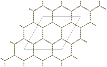
Graphdiyne46,47 is a unique carbon allotrope that belongs to the family of graphyne. It is a two-dimensional layer material composed of carbon atoms arranged in a periodic hollow lattice structure shown in Fig. 1. In graphdiyne, some carbon atoms form hexagons, like in graphene. However, these hexagons are linked through carbon chains, resulting in a more complex structure showing large triangular holes. The distinctive feature of graphdiyne is the presence of both sp-hybridized and sp2-hybridized carbon atoms. The sp2-hybridized C atoms are those forming the hexagons, and the chains joining those aromatic ring hexagons are formed by sp-hybridized C atoms, leading to –C![[triple bond, length as m-dash]](https://www.rsc.org/images/entities/char_e002.gif) C–C
C–C![[triple bond, length as m-dash]](https://www.rsc.org/images/entities/char_e002.gif) C– chains with alternating triple (acetylenic) and single bonds. The calculated bond lengths along the carbon chains are: 1.39, 1.23, 1.33, 1.23, and 1.39 Å, and the carbon–carbon bond lengths in the carbon hexagons are larger, with an average value of 1.43 Å. These bond lengths agree well with previous work.48 Because of the planar structure with triangular holes, GDY can be used as a membrane for the filtration of gases. The holes in the structure can also anchor metal clusters and the metal-functionalized GDY has been proposed as a promising material in catalysis and hydrogen storage.48,49
C– chains with alternating triple (acetylenic) and single bonds. The calculated bond lengths along the carbon chains are: 1.39, 1.23, 1.33, 1.23, and 1.39 Å, and the carbon–carbon bond lengths in the carbon hexagons are larger, with an average value of 1.43 Å. These bond lengths agree well with previous work.48 Because of the planar structure with triangular holes, GDY can be used as a membrane for the filtration of gases. The holes in the structure can also anchor metal clusters and the metal-functionalized GDY has been proposed as a promising material in catalysis and hydrogen storage.48,49
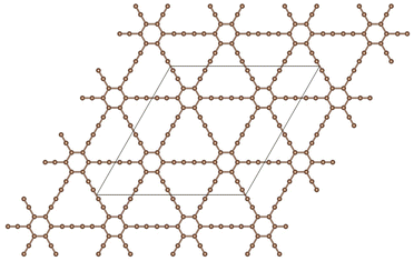 | ||
Fig. 1 Planar structure of graphdiyne, showing hexagonal rings linked by diacetylenic –C![[triple bond, length as m-dash]](https://www.rsc.org/images/entities/char_e002.gif) C–C C–C![[triple bond, length as m-dash]](https://www.rsc.org/images/entities/char_e002.gif) C– chains, which form large triangular holes. The unit cell used in the calculations is highlighted. C– chains, which form large triangular holes. The unit cell used in the calculations is highlighted. | ||
Boron graphdiyne, which has been synthesized by a bottom-up strategy,19 is a two-dimensional layer material that contains boron and carbon atoms in its structure. The structure of BGDY, shown in Fig. 2, consists of a honeycomb lattice made up of hexagons, like in graphene. However, in BGDY the vertices of the hexagons are occupied by boron atoms, and chains of C atoms join those B atoms and form the sides of the large hexagonal holes. The C atoms in the structure of BGDY form diacetylenic chains, like the chains in GDY. The calculated B–C bond length is 1.52 Å, and the bond lengths of triple C![[triple bond, length as m-dash]](https://www.rsc.org/images/entities/char_e002.gif) C bonds and single C–C bonds are 1.23 Å and 1.36 Å, respectively, close to the values in GDY and in agreement with previous work.49,50 The large hexagonal holes are a result of the boron atoms occupying the vertices of the hexagonal lattice. Because of the presence of these holes, the material can have applications in filtration membranes.
C bonds and single C–C bonds are 1.23 Å and 1.36 Å, respectively, close to the values in GDY and in agreement with previous work.49,50 The large hexagonal holes are a result of the boron atoms occupying the vertices of the hexagonal lattice. Because of the presence of these holes, the material can have applications in filtration membranes.
3.2 Adsorption of CO2 and CH4 on the membrane surface
CO2 is a linear molecule with calculated C–O bond distance of 1.20 Å. In methane, the four H atoms form a tetrahedron around a central C atom, and the calculated C–H bond distance is 1.09 Å. When the molecules of the gas mixture approach to the surface of the membrane, these molecules feel an attractive force due, at least, to the weak van der Waals interaction. But the force could be stronger if electrostatic or chemical interactions occur in addition. If the net attractive interaction is strong, the molecules will be trapped near the surface of the membrane, and passing through the membrane pores might be difficult. Of course, a barrier to cross the membrane may be present, as we discuss in the next section, and a deep interaction potential results in a high activation barrier. For this reason, it is important, as a first step, to know the strength of the adsorption energies of the molecules on the GDY and BGDY layers. The lowest energy adsorption configurations of one and several molecules (per hollow pore) on top of the GDY and BGDY layers were calculated, and the corresponding adsorption energies are reported in Table 1. The structures are given and described in the ESI.† The adsorption energy of a single CO2 molecule is defined| Eads(CO2) = E(CO2) + E(layer) − E(CO2-layer), | (1) |
| Eads(nCO2) = nE(CO2) + E(layer) − E(nCO2-layer), | (2) |
| n = 1 | n = 2 | n = 3 | n = 4 | |
|---|---|---|---|---|
| nCO2/BGDY | 0.121 | 0.272 (0.136) | 0.429 (0.143) | 0.614 (0.153) |
| nCH4/BGDY | 0.091 | 0.198 (0.099) | 0.331 (0.110) | |
| nCO2/GDY | 0.168 | 0.333 (0.167) | ||
| nCH4/GDY | 0.138 | 0.272 (0.136) |
Some results for mixed adsorption of nCO2 and mCH4 molecules are reported in Table 2. Total adsorption energies are compared with the sum nEads(CO2) + mEads(CH4), where the values of those sums, calculated from the data in Table 1, are given in parentheses. Again, the effect of the attractive dispersion interaction between the molecules is observed. In summary, the strength of the interaction energies (per molecule) of CO2 and CH4 with GDY and BGDY is small, and will not prevent the passing of the molecules trough the hollow pores.
| n = 1, m = 1 | n = 2, m = 3 | |
|---|---|---|
| Adsorption energy | 0.244 (0.212) | 0.695 (0.515) |
Further insight on the interaction between the CO2 molecule and the GDY and BGDY layers is provided by the electron density redistribution taking place upon adsorption of CO2 on those supporting layers, defined as
Δρ(![[r with combining right harpoon above (vector)]](https://www.rsc.org/images/entities/i_char_0072_20d1.gif) ) = ρCO2-layer( ) = ρCO2-layer(![[r with combining right harpoon above (vector)]](https://www.rsc.org/images/entities/i_char_0072_20d1.gif) ) − ρlayer( ) − ρlayer(![[r with combining right harpoon above (vector)]](https://www.rsc.org/images/entities/i_char_0072_20d1.gif) ) − ρCO2( ) − ρCO2(![[r with combining right harpoon above (vector)]](https://www.rsc.org/images/entities/i_char_0072_20d1.gif) ) ) | (3) |
![[r with combining right harpoon above (vector)]](https://www.rsc.org/images/entities/i_char_0072_20d1.gif) ) is the electron density of the system formed by the CO2 molecule adsorbed on the GDY (or BGDY) layer, and ρlayer(
) is the electron density of the system formed by the CO2 molecule adsorbed on the GDY (or BGDY) layer, and ρlayer(![[r with combining right harpoon above (vector)]](https://www.rsc.org/images/entities/i_char_0072_20d1.gif) ) and ρCO2(
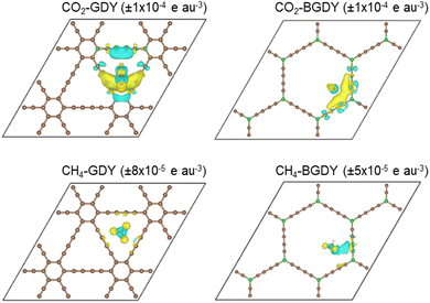
) and ρCO2(![[r with combining right harpoon above (vector)]](https://www.rsc.org/images/entities/i_char_0072_20d1.gif) ) are the densities of the separated GDY (or BGDY) layer and CO2 molecule, where the separated subsystems hold the same structure as in the adsorbed system. A similar definition applies to CH4 adsorption on GDY and BGDY. The electron density redistributions are shown in Fig. 3. The figure shows that the density redistribution is small in all cases. One can observe a tiny accumulation of electronic charge between the CO2 molecule and the two diacetylenic chains of GDY (or BGDY) closer to the molecule (notice the small value of the Δρ isodensity surface plotted) and a tiny polarization of the electron density in the CH4 molecule. The density redistribution concentrates mainly on the adsorbed CO2 or CH4 molecules, and the GDY and BGDY substrates are mostly unaffected. The electron density redistribution confirms the weak interaction (van der Waals type) between CO2 and CH4 molecules and GDY and BGDY layers, and the absence of electrostatic or chemical interactions between the molecules and the supporting layers that would impede the passing of the molecules through the pores of the layers.
) are the densities of the separated GDY (or BGDY) layer and CO2 molecule, where the separated subsystems hold the same structure as in the adsorbed system. A similar definition applies to CH4 adsorption on GDY and BGDY. The electron density redistributions are shown in Fig. 3. The figure shows that the density redistribution is small in all cases. One can observe a tiny accumulation of electronic charge between the CO2 molecule and the two diacetylenic chains of GDY (or BGDY) closer to the molecule (notice the small value of the Δρ isodensity surface plotted) and a tiny polarization of the electron density in the CH4 molecule. The density redistribution concentrates mainly on the adsorbed CO2 or CH4 molecules, and the GDY and BGDY substrates are mostly unaffected. The electron density redistribution confirms the weak interaction (van der Waals type) between CO2 and CH4 molecules and GDY and BGDY layers, and the absence of electrostatic or chemical interactions between the molecules and the supporting layers that would impede the passing of the molecules through the pores of the layers.
We are not aware of other works for the interaction of CO2 and CH4 with GDY or BGDY. But some information exists for the interaction of these molecules with other related carbon materials. DFT calculations of the adsorption energies of CO2 and CH4 with graphene have been performed.51–53 The adsorption energies of CO2 on graphene calculated by Wood et al.52 and Thierfelder et al.53 vary between 0.12 and 0.16 eV per molecule, depending on the exchange–correlation energy functional used, and the treatment of dispersion. These results are in good agreement with the experimental value of 0.127 eV per molecule. The calculated adsorption energy of CH4 is 0.24 eV per molecule.52 The adsorption energies obtained by Ossouledini et al.51 are smaller, 0.03 eV per molecule (CO2) and 0.05 eV per molecule (CH4). Overall, these results are consistent with the results in Table 1. All the adsorption energies reveal the fact that the attractive part of the interaction of CO2 and CH4 with the three planar substrates, graphene, GDY and BGDY, is weak, dominated by dispersion effects, although differences can be expected between the difference substrates. Ganji54 investigated the interaction of CO2 with carbon nanotubes using DFT, and obtained an adsorption energy of 0.38 eV per molecule. This energy is larger than the adsorption energies quoted above, and this can be understood as due to the higher reactivity of the curved nanotubes.
3.3 Vertical path of CO2 and CH4 through the center of the pores of GDY and BGDY
We now investigate the filtration of CO2 and CH4 through the GDY and BGDY membranes. The passing of these molecules through the hollow pores of GDY and BGDY has been first simulated by placing the molecules at a distance z above the center of a hollow pore, that is, fixing the (x, y, z) coordinates of the C atom of those molecules at (0, 0, z), and calculating the energy of the whole system, molecule and membrane layer, for several different distances z of approach (these conditions will be relaxed in Section 3.4). For each value of z, the orientation of the molecules, and also the interatomic distances in the molecule, and the coordinates of the atoms of the membranes are fully relaxed to optimize the energies. In this way, the potential energy of the molecule along a path (with x = y = 0) approaching the layer is obtained.The energy versus distance z is plotted in Fig. 4. The main difference between the GDY and BGDY membranes is that the strength of the interaction between these molecules and BGDY is substantially lower than their interaction with GDY. This is due to the larger size of the holes in BGDY. The minimum of the potential energy curves occurs near z = 2–3 Å in GDY, and at z = 0 in BGDY. This means that there is an activation barrier for the passing of CO2 and CH4 through the triangular holes of GDY (notice that the potential energy curve is symmetrical with respect to the layer plane). The magnitude of the barrier is quite different: 0.28 eV for CO2, and 0.51 eV for CH4. On the other hand, the passing of the two molecules through the hexagonal holes of BGDY is much easier: the depth of the minimum at z = 0 is tiny, with values of −0.029 for CO2, and −0.030 eV for CH4, and there are no barriers for the passing from one side of the membrane layer to the other.
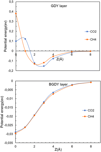 | ||
| Fig. 4 Energy as a function of the distance z between the CO2 or CH4 molecules and the layer. Upper panel, GDY. Lower panel, BGDY. The (x, y) coordinates of the molecule are x = 0, y = 0. | ||
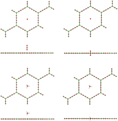
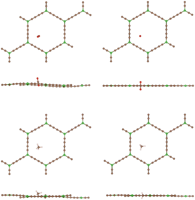
The particular orientation of the molecular axis of the linear CO2 molecule is not relevant when the molecule is far away, or at least not close to the GDY layer. At distances z near the potential energy minimum, the orientation of the CO2 axis is a bit tilted with respect to the plane of the GDY layer; see Fig. 5. However, the orientation becomes perpendicular when the molecule approaches closely the layer. This reorientation of the molecular axis occurs spontaneously in the calculations, because it lowers the short-range Pauli repulsion with the pore walls and facilitates the crossing of the molecule through the narrow hole. The vertical orientation of the axis can be interpreted as a way of decreasing the effective size of the CO2 molecule, as sensed by the pore boundaries, in comparison to other molecular orientations, when passing through the hole. On the other hand, the shape of CH4 is nearly spherical, and its orientation is not relevant. The boundaries of the hole deform slightly through the crossing of CH4, but not through the crossing of CO2 (due to the favorable orientation). The boundaries of the large hexagonal holes of BGDY do not suffer deformation through the passing of CO2 or CH4, as shown in Fig. 6.
To clarify the nature of the interaction between these molecules and the GDY and BGDY layers, the interaction energy and its attractive van der Waals contribution are plotted in Fig. 7 for the case of CO2 interacting with GDY. The two curves are very close until the molecule approaches the layer at a distance of 3 Å. However, as the molecule approaches closer to the layer, the total interaction turns repulsive because the molecule does not fit well into the triangular hole due to the short-range repulsive interaction with the pore walls, and some energy has to be invested to go through.
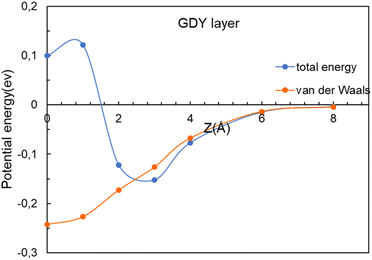 | ||
| Fig. 7 Energy as a function of the distance z between the CO2 molecule and the GDY layer. The (x, y) coordinates of the molecule are x = 0, y = 0. The van der Waals contribution is also included. | ||
3.4 Relaxation of the crossing path
The straight vertical path (0, 0, z) through the center of the hollow pores serves to illustrate well the form of the potential energy of interaction (see Fig. 4). However, in their travel the molecules might deviate from the (0, 0, z) vertical path if this lowers the potential energy. New calculations have been performed by allowing for those deviations. That is, at each specific value of the z coordinate of the center of mass of the molecule (vertical distance to the layer) the x and y coordinates of the center of mass were allowed to relax to optimize the energy, in addition to the full relaxation of the orientation and interatomic distances of the molecule and the positions of all the atoms of the membrane. The improved interaction potentials for the passing of CO2 and CH4 through the GDY pores are plotted in Fig. 8. By comparison with Fig. 4, no appreciable changes are observed in the potential energies of the two molecules. The positions of the energy minima and the magnitude of the activation barriers are practically the same as in Fig. 4. The position and orientation of the molecules near the potential energy minimum, and at z = 0 are practically indistinguishable from those in Fig. 5; that is, the deviation of the path of the molecules from the path with x = y = 0 is negligible. The main conclusion from Fig. 4 and 8, is that the different heights of the barriers for CO2 and CH4 reveal the excellent selectivity of the GDY:CO2 molecules will pass much more easily than CH4 molecules through the triangular holes. And one can profit from this fact to purify commercial gas, and to capture the CO2.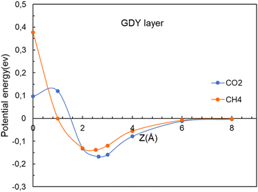 | ||
| Fig. 8 Energy as a function of the distance z between the CO2 and CH4 molecules and the GDY layer. The (x, y) coordinates of the molecules are relaxed for each value of z. | ||
In sharp contrast, in the case of BGDY, with large hexagonal pore holes, the relaxation of the (x, y) coordinates of the molecules affects substantially their potential energies. Fig. 9 shows that the minima of the potential energy curves become deeper in comparison to Fig. 4, because the path of the molecules moves a bit towards one corner of the hexagon (see Fig. 10), in this way increasing the attractive van der Waals interaction with the layer. The barriers for the crossing of CO2 and CH4 molecules from one side of the BGDY layer to the other through the hexagonal holes are negligibly small, and the depth of the potential confining the molecules in the region close to the layer is small in both cases, and easily surmountable under the usual filtration conditions. This means that BGDY is much less effective to separate CO2 and CH4.
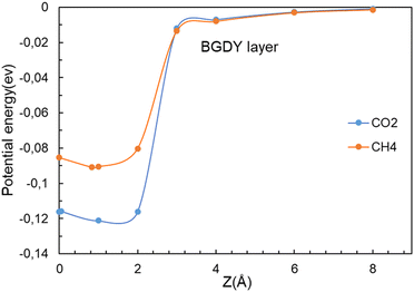 | ||
| Fig. 9 Energy as a function of the distance z between the CO2 and CH4 molecules and the BGDY layer. The (x, y) coordinates of the molecules are relaxed for each value of the vertical distance z. | ||
4 Discussion
The potential energy minima at distances of 2–3 Å from the GDY layer shown in Fig. 8 indicate that there is a stable adsorption configuration for CO2 and CH4 when these molecules are close to the GDY layer. This is mainly due to the attractive van der Waals interactions between the molecules and the GDY, and the depths of the minima are small. The barrier to go through the hollow cavities arises because the sizes of these molecules and the size of the pores are relatively similar. However, the barrier for CO2 is smaller than the barrier for CH4, because CO2 is a linear molecule that can adopt a favorable orientation, perpendicular to the layer, to cross the holes. On the other hand, CH4 is nearly spherical and cannot profit from a favorable orientation. Fig. 11 shows the electronic densities of CO2 and CH4 at the point of passing through the GDY membrane, that is, at z = 0. At this point, the axis of the CO2 molecule is, as mentioned above, perpendicular to the GDY layer. Surfaces of constant density with a value 0.01 e a.u.−3 have been plotted, and these reflect well the difference in size of the two molecules that permits the easier crossing of CO2 through the triangular hole.The energy barriers are critical for controlling the permeation of molecules through the material. Smaller activation barriers indicate that it is easier for those molecules to pass through. This property can be exploited to create selective membranes allowing certain molecules to pass, while inhibiting others. In our case, GDY membranes will be able to separate a mixture of CO2 and CH4, allowing the purification of natural gas and biogas, as well as the capture of the CO2.
The relative sizes of the pores and gas molecules are the major factor determining what molecules can pass easily through the membrane. The sizes of CO2 and CH4 are quite similar, the experimental bond-lengths being d(C–O) = 1.16 Å, and d(C–H) = 1.09 Å. But CO2 is a linear molecule, and by adopting the vertical orientation with respect to the membrane layer, its effective size when passing through the hollow pore is much reduced.
The size of the hexagonal pores in BGDY is substantially larger than the sizes of CO2 and CH4, and these molecules will easily pass through the layer holes. The molecules have a tendency to deviate from the x = y = 0 path, a fact that increases the attractive part of the interaction with the BGDY layer, but the passing through the hollow pores is still easy because there is no activation barrier. BGDY will not serve to separate CO2 and CH4, but could serve to separate CO2 and CH4 from larger molecules, like large hydrocarbons.
To quantitatively assess the capacity of GDY to separate CO2 and CH4, the selectivity of the membrane and the permeances of the two gases can be calculated. The selectivity of the GDY membrane to separate CO2 and CH4 can be obtained by starting from Arrhenius equation
 | (4) |
 | (5) |
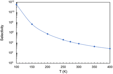
The selectivity as a function of the temperature is shown in Fig. 12 (the actual values are given in Table S2 of the ESI†). Evidently, the selectivity decreases with increasing temperature. But at room or lower temperatures the selectivity is substantial and promising, reaching a value near 104 at room temperature, which guarantees an efficient separation of the two gases, and the capture of the CO2 component. Selectivities of this order have been obtained in works for other gas mixtures.28,29
The permeance of a membrane for a gas28 is defined by
| P = F/Δp. | (6) |
In this equation, F is the gas molar flux through the membrane, and Δp the pressure difference between the two sides of the membrane. F is calculated as F = Nf, where N represents the number of gas molecules per unit surface and unit time colliding with the membrane, and f is the probability for a particle to diffuse through the pore at a given velocity. The kinetic theory of gases allows to write N as
 | (7) |
 | (8) |
 | (9) |
Therefore, the probability f is given by
 | (10) |
Taking into account the properties of the Gaussian integral,57f becomes
 | (11) |
 | (12) |
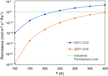
The calculated permeances of CO2 and CH4 through GDY are plotted in Fig. 13 as a function of the temperature, for an incoming pressure p = 3 × 10⁵ Pa and a pressure difference between the two sides of the membrane Δp = 105 Pa. The permeance of CO2 is higher than the permeance of CH4, which is consistent with the calculated selectivity of GDY. The horizontal line plotted in this Figure marks the industrial permeance limit for gas separation processes, which is 6.7 × 10⁻⁹ mol m−2 s−1 Pa−1. These results confirm that GDY can act as a porous membrane for the effective separation of CO2 and CH4, and for the capture of the CO2 in the natural gas industry.
5 Conclusions
The capacity of GDY and BGDY nanoporous membranes to separate CO2 and CH4 in a CO2/CH4 gas mixture has been investigated. This process is relevant in the purification of natural gas, landfill gas, and biogas. The strength of the interaction between these two molecules and GDY or BGDY is small. Consequently, these molecules are not chemically bound to the membrane layers, and passing through the holes of the GDY and BGDY membranes is possible under the usual filtration conditions. A crucial difference between the two membranes is that the size of the hexagonal pores in BGDY is large in comparison to the size of the two molecules, and the crossing of these molecules through the pores of BGDY is easy because of the lack of activation barriers. Then, BGDY is not efficient to separate CO2 and CH4. On the other hand, the size of the triangular pores in GDY is smaller, comparable to the diameters of the two molecules, and this builds up an activation barrier for the passing of the molecules. The height of the barrier for CO2 is approximately one half of that for CH4. The reason is that CO2 is a linear molecule which adopts an orientation perpendicular to the GDY layer to cross the pores, in this way reducing its effective size during the crossing process. In contrast, CH4 has a spherical-like shape, and cannot profit from a favorable orientation. For these reasons, the calculated selectivity of the GDY membrane for CO2/CH4 separation is large, and favors the passing of CO2. The calculated permeances are consistent with the selectivity. This makes GDY a very promising membrane material for the purification of commercial gas and for the capture of its CO2 component.Author contributions
Sahar Mahnaee: conceptualization; formal analysis; investigation; writing – original draft; visualization. María J. López: conceptualization; formal analysis; investigation; writing – review & editing; supervision; funding acquisition. Julio A. Alonso: conceptualization; formal analysis; investigation; writing – original draft; writing – review & editing; supervision.Conflicts of interest
There are no conflicts to declare.Acknowledgements
Work supported by Ministerio de Ciencia e Innovación of Spain (grants PID2019-104924RB-I00 funded by MCIN/AEI/10.13039/501100011033, and PID2022-138340OB-I00 funded by MCIN/AEI/10.13039/501100011033 and FSE+), and the University of Valladolid (GIR Nanostructure Physics Group). S. M. acknowledges a predoctoral contract with the University of Valladolid.References
- Carbon capture, storage and utilization: a possible climate change solution for energy industry, ed. M. Goel, M. Sudhakar, and R. V. Sahi, CRC Press, 2019 Search PubMed.
- X. Yuan Chen, H. Vinh-Thang, A. Avalos Ramirez, D. Rodrigue and S. Kaliaguine, Membrane gas separation technologies for biogas upgrading, RSC Adv., 2015, 5, 24399–24448, 10.1039/C5RA00666J.
- A. Alonso, J. Moral-Vico, A. Abo Markeb, M. Busquets-Fité, D. Komilis, V. Puntes, A. Sánchez and X. Font, Critical review of existing nanomaterial adsorbents to capture carbon dioxide and methane, Sci. Total Environ., 2017, 595, 51–62, DOI:10.1016/j.scitotenv.2017.03.229.
- N. Azni Farhana Mazria, A. Arifutzzamana, M. Kheireddine Arouaa, M. Ekhlasur Rahmand and S. Ali Mazari, Graphene and its tailoring as emerging 2D nanomaterials in efficient CO2 absorption: A state-of-the-art interpretative review, Alexandria Eng. J., 2023, 77, 479–502, DOI:10.1016/j.aej.2023.06.070.
- A. G. Olabi, A. H. Alami, M. Ayoub, H. Aljaghoub, S. Alasad, A. Inayat, M. A. Abdelkareem, K.-J. Chae and E. T. Sayed, Membrane-based carbon capture: Recent progress, challenges, and their role in achieving the sustainable development goals, Chemosphere, 2023, 320, 137996, DOI:10.1016/j.chemosphere.2023.137996.
- F. M. Baena-Moreno, E. le Saché, L. Pastor-Pérez and T. R. Reina, Membrane-based technologies for biogas upgrading: a review, Environ. Chem. Lett., 2020, 18, 1649–1658, DOI:10.1007/s10311-020-01036-3.
- M. Farnam, Hilmi bin Mukhtar and Azmi bin Mohd Shariff, A Review on Glassy and Rubbery Polymeric Membranes for Natural Gas Purification, ChemBioEng Rev., 2021, 8(2), 90–109, DOI:10.1002/cben.202100002.
- H. Demir, G. O. Aksu, H. C. Gulbalkan and S. Keskin, MOF Membranes for CO2 Capture: Past, Present and Future, Carbon Capture Sci. Technol., 2022, 2, 100026 CrossRef CAS.
- W. Li, K. Goh, C. Y. Chuah and T.-H. Bae, Mixed-matrix carbon molecular sieve membranes using hierarchical zeolite: A simple approach towards high CO2 permeability enhancements, J. Membr. Sci., 2019, 588, 117220 CrossRef CAS.
- D. Chen, K. Wang, Z. Yuan, Z. Lin, M. Zhang, Y. Li, J. Tang, Z. Liang, Y. Li, L. Chen, L. Li, X. Huang, S. Pan, Z. Zhu, Z. Hong and X. He, Boosting membranes for CO2 capture toward industrial decarbonization, Carbon Capture Sci. Technol., 2023, 7, 100117 CrossRef CAS.
- A. R. Nabais, S. Ahmed, M. Younis, J.-X. Zhou, J. R. Pereira, F. Freitas, D. Mecerreyes, J. G. Crespo, M. H. Huang and L. A. Neves, et al., Mixed matrix membranes based on ionic liquids and porous organic polymers for selective CO2 separation, J. Membr. Sci., 2022, 660, 120841 CrossRef CAS.
- N. N. R. Ahmad, C. P. Leo and A. W. Mohammad, Enhancement on the CO2 separation performance of mixed matrix membrane using ionic liquid, Mater. Lett., 2021, 304, 130736 CrossRef CAS.
- H. Guo, J. Wei, Y. Ma, J. Deng, S. Yi, B. Wang, L. Deng, X. Jiang and Z. Dai, Facilitated transport membranes for CO2/CH4 separation—State of the art, Adv. Membr., 2022, 2, 100040 CrossRef.
- S. Blankenburg, M. Bieri, R. Fasel, K. Müllen, C. A. Pignedoli and D. Passerone, Porous graphene as an atmospheric nanofilter, Small, 2010, 6, 2266e71 CrossRef PubMed.
- H. W. Kim, H. W. Yoon, S.-M. Yoon, B. M. Yoo, B. K. Ahn, Y. H. Cho, H. J. Shin, H. Yang, U. Paik, S. Kwon, J.-Y. Choi and H. B. Park, Selective Gas Transport Through Few-Layered Graphene and Graphene Oxide Membranes, Science, 2013, 342, 91, DOI:10.1126/science.1236098.
- N. Razmara, A. Kirch, J. Romano Meneghini and C. Rodrigues Miranda, Efficient CH4/CO2 gas mixture separation through nanoporous graphene membrane designs, Energies, 2021, 14, 2488, DOI:10.3390/en14092488.
- A. Ali, M. Aamir, K. H. Thebo and J. Akhtar, Laminar graphene oxide membranes towards selective ionic and molecular separations: Challenges and progress, Chem. Rec., 2019, 19, 1–12, DOI:10.1002/tcr.201900024.
- G. Li, Y. Li, H. Liu, Y. Guo, Y. Lia and D. Zhu, Architecture of graphdiyne nanoscale films, Chem. Commun., 2010, 46, 3256–3258, 10.1039/B922733D.
- N. Wang, X. Li, Z. Tu, F. Zhao, J. He, Z. Guan, C. Huang, Y. Yi and Y. Li, Synthesis and electronic structure of boron-graphdiyne with an sp-hybridized carbon skeleton and its application in sodium storage, Angew. Chem., Int. Ed., 2018, 57, 3968–3973, DOI:10.1002/anie.201800453.
- N. V. Rao Nulakani and V. Subramanian, J. Phys. Chem. C, 2016, 120(28), 15153–15161, DOI:10.1021/acs.jpcc.6b03562.
- L. Zhao, P. Sang, S. Guo, X. Liu, J. Li, H. Zhu and W. Guo, Promising monolayer membranes for CO2/N2/CH4 separation: Graphdiynes modified respectively with hydrogen, fluorine, and oxygen atoms, Appl. Surf. Sci., 2017, 405, 455–464, DOI:10.1016/j.apsusc.2017.02.054.
- M. Bartolomei, E. Carmona-Novillo, M. I. Hernández, J. Campos-Martínez, F. Pirani and G. Giorgi, Graphdiyne pores: “Ad hoc” openings for helium separation applications, J. Phys. Chem. C, 2014, 118, 29966–29972, DOI:10.1021/jp510124e.
- E. García-Arroyo, J. Campos-Martínez, M. Bartolomei, F. Pirani and M. I. Hernández, Molecular hydrogen isotope separation by a graphdiyne membrane: a quantum-mechanical study, Phys. Chem. Chem. Phys., 2022, 24, 15840–15850, 10.1039/D2CP01044E.
- S. W. Cranford and M. J. Buehler, Selective hydrogen purification through graphdiyne under ambient temperature and pressure, Nanoscale, 2012, 4, 4587–4593, 10.1039/C2NR30921A.
- K. Xu, N. Liao, M. Zhang and W. Xue, Atomic-scale investigations of enhanced hydrogen separation performance from doping boron and nitrogen in graphdiyne membrane, Int. J. Hydrogen Energy, 2020, 45, 28893–28902, DOI:10.1016/j.ijhydene.2020.07.174.
- Y. Jiao, A. Du, M. Hankel, Z. Zhu, V. Rudolph and S. C. Smith, Graphdiyne: a versatile nanomaterial for electronics and hydrogen purification, Chem. Commun., 2011, 47, 11843–11845, 10.1039/C1CC15129K.
- X. Zhang, R. Fang, D. Chen and G. Zhang, Using Pd-doped-graphyne to detect dissolved gases in transformer oil: A density functional theory investigation, Nanomaterials, 2019, 9, 1490, DOI:10.3390/nano9101490.
- Z. Meng, X. Zhang, Y. Zhang, H. Gao, Y. Wang, Q. Shi, D. Rao, Y. Liu, K. Deng and R. Lu, Graphdiyne as a high-efficiency membrane for separating oxygen from harmful gases: A first-principles study, ACS Appl. Mater. Interfaces, 2016, 8, 28166–28170, DOI:10.1021/acsami.6b08662.
- P. Rezaee and H. R. Naeij, A new approach to separate hydrogen from carbon dioxide using graphdiyne-like membrane, Sci. Rep., 2020, 10, 13549, DOI:10.1038/s41598-020-69933-9.
- Y. B. Apriliyanto, N. Faginas Lago, A. Lombardi, S. Evangelisti, M. Bartolomei, T. Leininger and F. Pirani, Nanostructure selectivity for molecular adsorption and separation: the case of graphyne layers, J. Phys. Chem. C, 2018, 122, 16195–16208, DOI:10.1021/acs.jpcc.8b04960.
- H. Hamyali, F. Nosratinia, A. Rashidi and M. Ardjmand, Anthracite coal-derived activated carbon as an effectiveness adsorbent for superior gas adsorption and CO2/N2 and CO2/CH4 selectivity: Experimental and DFT study, J. Environ. Chemical Engineering, 2022, 10, 107007, DOI:10.1016/j.jece.2021.107007.
- S. Rafiq, Z. Man, A. Maulud, N. Muhammad and S. Maitra, Separation of CO2 from CH4 using polysulfone/polyimide silica nanocomposite membranes, Sep. Purif. Technol., 2012, 90, 162–172, DOI:10.1016/j.seppur.2012.02.031.
- M. Rezakazemi, A. Ebadi Amooghin, M. M. Montazer-Rahmati, A. Fauzi Ismail and T. Matsuura, State-of-the-art membrane based CO2 separation using mixed matrix membranes (MMMs): An overview on current status and future directions, Prog. Polym. Sci., 2014, 39, 817–861, DOI:10.1016/j.progpolymsci.2014.01.003.
- N. M. Ismail, A. F. Ismail and A. Mustaffa, Characterization of polyethersulfone/cloisite 15A mixed matrix membrane for CO2/CH4 separation, J. Teknol. Lab., 2014, 69, 83–87, DOI:10.11113/JT.V69.3402.
- A. Jamil, O. P. Ching and A. M. Shariff, Mixed matrix hollow fibre membrane comprising polyetherimide and modified montmorillonite with improved filler dispersion and CO2/CH4 separation performance, Appl. Clay Sci., 2017, 143, 115–124, DOI:10.1016/j.clay.2017.03.017.
- D. S. Sholl and J. A. Steckel, Density Functional Theory, Wiley, Hoboken, 2009 Search PubMed.
- P. Giannozzi, S. Baroni, N. Bonini, M. Calandra, R. Car, C. Cavazzoni, D. Ceresoli, G. L. Chiarotti, M. Cococcioni and I. Dabo, et al., QUANTUM ESPRESSO: a modular and open-source software project for quantum simulations of materials, J. Phys.: Condens. Matter, 2009, 21, 395502, DOI:10.1088/0953-8984/21/39/395502.
- https://www.quantumespresso.org (accessed 19 February 2024).
- J. P. Perdew, K. Burke and M. Ernzerhof, Generalized gradient approximation made simple, Phys. Rev. Lett., 1966, 77, 3865–3868, DOI:10.1103/PhysRevLett.77.3865.
- G. Kresse and D. Joubert, From ultrasoft pseudopotentials to the projector augmented wave method, Phys. Rev. B: Condens. Matter Mater. Phys., 1999, 59, 1758–1775, DOI:10.1103/PhysRevB.59.1758.
- P. E. Blöchl, Projector augmented-wave method, Phys. Rev. B: Condens. Matter Mater. Phys., 1994, 50, 17953–17979, DOI:10.1103/PhysRevB.50.17953.
- S. Grimme, J. Antony, S. Ehrlich and H. Krieg, A consistent and accurate ab initio parametrization of density functional dispersion correction (DFT-D) for the 94 elements H-Pu, J. Chem. Phys., 2010, 132, 154104, DOI:10.1063/1.3382344.
- L. Goerigk, in A comprehensive overview of the DFT-D3 London-dispersion correction, ed. A. Otero de la Roza, and G. A. DiLabio, Non-Covalent Interactions in Quantum Chemistry and Physics, Elsevier, 2017, pp. 195–219 DOI:10.1016/B978-0-12-809835-6.00007-4.
- I. Cabria, M. J. López and J. A. Alonso, Searching for DFT-based methods that include dispersion interactions to calculate the physisorption of H2 on benzene and graphene, J. Chem. Phys., 2017, 146, 214104, DOI:10.1063/1.4984106.
- H. J. Monkhorst and J. D. Pack, Special points for Brillouin-zone integrations, Phys. Rev. B: Solid State, 1976, 13, 5188–5192, DOI:10.1103/PhysRevB.13.5188.
- X. Gao, H. Liu, D. Wang and J. Zhang, Graphdiyne: synthesis, properties, and applications, Chem. Soc. Rev., 2019, 48, 908–936, 10.1039/C8CS00773J.
- Y. Du, W. Zhou, J. Gao, X. Pan and Y. Li, Fundament and application of graphdiyne in electrochemical energy, Acc. Chem. Res., 2020, 53, 459–469, DOI:10.1021/acs.accounts.9b00558.
- A. Seif, M. J. López, A. Granja-DelRío, K. Azizi and J. A. Alonso, Adsorption and growth of palladium clusters on graphdiyne, Phys. Chem. Chem. Phys., 2017, 19, 19094–19102, 10.1039/C7CP03263C.
- E. German, J. Sandoval, A. Recio, A. Seif, J. A. Alonso and M. J. López, Supported metal nanohydrides for hydrogen storage, Chem. Mater., 2023, 35, 1134–1147, DOI:10.1021/acs.chemmater.2c03106.
- E. Germán, A. Alvarez-Yenes, J. A. Alonso and M. J. López, Adsorption of transition metal clusters on Boron-graphdiyne, Appl. Surf. Sci., 2021, 548, 149270, DOI:10.1016/j.apsusc.2021.149270.
- N. Osouleddini and S. F. Rastegar, DFT study of the CO2 and CH4 assisted adsorption on the surface of graphene, J. Electron. Spectrosc. Relat. Phenom., 2019, 232, 105–110, DOI:10.1016/j.elspec.2018.11.006.
- B. C. Wood, S. Y. Bhide, D. Dutta, V. S. Kandagal, A. D. Pathak, S. N. Punnathanam, K. G. Ayappa and S. Narasimhan, Methane and carbon dioxide adsorption on edge-functionalized graphene: A comparative DFT study, J. Chem. Phys., 2012, 137, 054702, DOI:10.1063/1.4736568.
- C. Thierfelder, M. Witte, S. Blankenburg, E. Rauls and W. G. Schmidt, Methane adsorption on graphene from first principles including dispersion interaction, Surf. Sci., 2011, 605, 746–749, DOI:10.1016/j.susc.2011.01.012.
- M. D. Ganji, Theoretical study of the adsorption of CO2 on tungsten carbide nanotubes, Phys. Lett. A, 2008, 372, 3277–3282, DOI:10.1016/j.physleta.2008.01.032.
- P. Sang, L. Zhao, J. Xu, Z. Shi, S. Guo, Y. Yu, H. Zhu, Z. Yan and W. Guo, Excellent membranes for hydrogen purification: Dumbbell-shaped porous-graphynes, Int. J. Hydrogen Energy, 2017, 42, 5168–5176, DOI:10.1016/j.ijhydene.2016.11.158.
- Y. F. Li, Z. Zhou, P. W. Shen and Z. F. Chen, Two-dimensional polyphenylene: experimentally available porous graphene as a hydrogen purification membrane, Chem. Commun., 2010, 46, 3672–3674, 10.1039/B926313F.
- M. Abramowitz and I. A. Stegun, Handbook of Mathematical Functions. Dover Publications, New York, 1972 Search PubMed.
Footnote |
| † Electronic supplementary information (ESI) available. See DOI: https://doi.org/10.1039/d4cp00872c |
| This journal is © the Owner Societies 2024 |

