
 Open Access Article
 This Open Access Article is licensed under a
 Creative Commons Attribution 3.0 Unported Licence
Impact of long-range attraction on desorption kinetics†
Florian
Schneider
 *a,
Lukas
Höltkemeier
a,
Andrea
Floris
b,
Lev
Kantorovich
c,
Ralf
Bechstein
a and
Angelika
Kühnle
*a
*a,
Lukas
Höltkemeier
a,
Andrea
Floris
b,
Lev
Kantorovich
c,
Ralf
Bechstein
a and
Angelika
Kühnle
*a
aFaculty of Chemistry, Physical Chemistry I, Bielefeld University, 33615 Bielefeld, Germany. E-mail: fschneider8@uni-bielefeld.de; angelika.kuehnle@uni-bielefeld.de
bSchool of Chemistry, University of Lincoln, Brayford Pool, Lincoln LN6 7TS, UK
cDepartment of Physics, Kings College London, London WC2R 2LS, UK
First published on 27th February 2024
Abstract
Desorption of molecules from surfaces is widespread both in nature and technology. Despite its omnipresence and conceptual simplicity, fundamental details can be surprisingly complex and are often poorly understood. In many cases, first-order kinetics is assumed, which implies that the adsorbates do not interact with each other and desorption is the rate-limiting process. While this might be a good approximation in some cases, it is far from reality in the case of adsorbates that form ordered structures. Here, we study the desorption of a submonolayer film of 3-nitrophenol from the natural cleavage plane of calcite kept in ultrahigh vacuum. Interestingly, two distinctly different desorption regimes are observed during isothermal desorption monitored by dynamic atomic force microscopy. Initially, at high coverages, the coverage decreases almost linearly in time, indicating a constant desorption rate. Beyond this linear regime, at low coverages, a drastic increase in desorption rate is observed until the surface is completely empty. The transition between these two regimes is associated with a critical island width. We propose an existence of a long-range attractive interaction between the molecules as a possible explanation for the sudden increase in the desorption rate when a critical island width is reached. The herein observed phenomenon of two different desorption regimes is expected to be of general nature when interactions beyond next-neighbour attraction are present.
1 Introduction
Desorption of adsorbed atoms and molecules from a surface1–3 is an omnipresent phenomenon in nature and technology, for example during drying of wet surfaces or within heterogeneous catalysis.4,5 The desorption process is often considered to follow first-order kinetics, i.e., the rate is proportional to the coverage.6 This assumption implies that adsorbate–adsorbate interactions can be neglected. Due to the fact that a large number of adsorbates form well-ordered islands on surfaces, adsorbate–adsorbate interactions do, however, play a significant role in many cases. Thus, complex desorption kinetics are expected, which strongly depend on the interactions of the adsorbates and their local arrangement on the surface.Scanning probe techniques are appropiate to analyse such complex desorption kinetics by repeatedly scanning the same surface area over a long time and tracking the desorption. This has been done in ultrahigh vacuum (UHV) environment with scanning tunneling microscopy (STM),7 atomic force microscopy (AFM)8 and low-energy electron microscopy (LEEM).9 In liquid environments, STM and AFM experiments are frequently used to investigate desorption processes.10–14
Here, we present isothermal desorption curves obtained from long-time AFM measurements of 3-nitrophenol (C6H5NO3) desorbing from the (10.4) surface of calcite. All desorption curves exhibit two regimes. At high coverages, an almost linear regime is observed, which indicates desorption with a constant desorption rate. However, when a low coverage is reached, the desorption rate increases drastically. We were able to correlate this desorption rate increase with a critical island width, indicating that the drastic increase of the desorption rate might be caused by a reduction of the influence of a long-range interaction between the molecules. The herein reported increase of the desorption rate at low coverage is expected to be of general nature as long as interactions beyond next neighbours are present.
2 Methods
Experimental methods
Atomic force microscopy (AFM) experiments were performed in an ultrahigh vacuum (UHV) chamber (Scienta Omicron, Germany) with a base pressure in the low 10−10 mbar range. The calcite crystal (Korth Kristalle GmbH, Germany) was degassed in UHV at 750 K for 50 min and afterwards cleaved in situ to ensure a clean (10.4) surface. Before the AFM measurements, the calcite crystal was annealed at 500 K for 1 h to reduce the high surface charges caused by cleavage. After sample preparation, 3-nitrophenol (Sigma-Aldrich, purity ≥98.5%) was deposited onto the calcite surface with a Knudsen cell sublimator at room temperature. We performed long-time AFM measurements at 310 K, 315 K and 330 K, tracking the desorption process. Several different series of AFM images were collected at different temperatures. The AFM measurements were performed in the frequency-modulation mode. The images were measured with 500 × 500 pixels and a measurement time of 400 μs per pixel. This corresponds to a scan time per image of 200 s, including trace and retrace. The temperature was controlled with a temperature controller (Lakeshore) through heating. Image processing and analysis (see ESI† Section S1) were performed with Gwyddion,15 unDrift16 and Fiji.17 We estimate the temperature stability to be within 0.5 K at the beginning, reducing to 0.1 K during the course of the experiment. The actual value of the temperature is expected to have a much larger error and is difficult to quantify. For the present work, however, the actual value of the temperature is not relevant as long as the temperature is constant during each individual experiment.Computational methods
3 Results and discussion
To get insights into the adsorption structure of 3-nitrophenol (Fig. 1a) on the calcite (10.4) surface (Fig. 1b), high-resolution AFM images were collected with the sample kept at 300 K. Fig. 1c shows an island border, which separates the 3-nitrophenol island on the left from the clean calcite surface on the right. The island border appears fuzzy, indicating fast attachment and detachment. The calcite (10.4) surface is known to reconstruct in UHV forming a (2 × 1) unit cell,25 which is marked by a grey rectangle in Fig. 1c. The molecules form a commensurate superstructure with two protrusions within the unit cell, which is marked by a blue rectangle in Fig. 1c. Thus, each calcite (2 × 1) unit cell is most likely occupied by two upright 3-nitrophenol molecule. This assignment is motivated by a comparison with dihydroxybenzoic acid having a similar size as 3-nitrophenol.26 | ||
| Fig. 1 (a) Model of 3-nitrophenol. (b) Calcite (10.4) surface model. (c) AFM image with atomic resolution of a 3-nitrophenol island edge measured at 300 K. The (2 × 1) unit cell of the adsorbate (calcite) is marked by a blue (grey) rectangle. (d) AFM image of a calcite step edge, which separates two terraces. Both terraces are covered with a submonolayer film of 3-nitrophenol. | ||
Fig. 1d shows a calcite step edge (faint line) running from the lower left to the upper right and separating two calcite terraces. Both terraces are covered with a submonolayer film of 3-nitrophenol, exhibiting vacancy islands (darker areas), which expose the bare calcite. It is interesting to note that directly at the step edge the lower terrace is occupied by molecules while the upper terrace is barely covered in the proximity of the step edge. For this study, however, we focus on areas without step edges to exclude the effect of step edges on the desorption process. To gain insights into the desorption process, we performed long-time AFM measurements at 310 K, 315 K and 330 K, tracking the desorption process (ESI† Section S3 and videos: 310 K, 315 K-1, 315 K-2, 330 K and 310 Kdifference). Two measurement series were taken at 315 K. We collected series of AFM images with the sample kept at constant temperature. For each image, we analysed the molecular coverage by thresholding (ESI† Sections S1 and S2) to arrive at a representation with the bare calcite surface being black (0) and the molecule-covered part being white (1). Subsequently, we calculated the average grey value (arithmetic mean), which is interpreted as the coverage (ESI† eqn (S1)).
In Fig. 2a, the molecular coverage on the sample when kept at 310 K is plotted against time. Two distinct regimes can be observed: In the first regime, an almost linear decrease of the coverage is found until about 0.35 ML is reached. In the second regime, the coverage decreases with a much higher rate, visible as a steep drop of the coverage. Furthermore, three AFM images are shown in Fig. 2b–d selected from the linear regime (Fig. 2b), towards the end of the linear regime (Fig. 2c) and from the fast-desorption regime (Fig. 2d). All images have a size of 1500 × 1500 nm2. In Fig. 2e–g, the same images are shown again with a red overlay indicating the island area that vanishes during the following 33 minutes (i.e., the next five images). The red overlays to the images are obtained by subtracting the actual image from the image taken 33 minutes later. Vanishing structures are colored red while unchanged structures are colored as before. Minor deviations at the island borders might be caused by thermal drift. In the following, we will discuss these images as well as the desorption rate in both regimes in more detail.
 | ||
| Fig. 2 (a) Isothermal desorption curve of 3-nitrophenol desorbing from calcite (10.4) determined by long-time AFM measurements. (b)–(d) AFM images with a size of 1500 × 1500 nm2. The images were edited by thresholding to arrive at a representation with the bare calcite surface being black and the molecule-covered part white. Details can be found in the ESI† (Section S1). Two exemplary vacancy islands with different orientations are marked by turquoise rectangles. (e)–(g) Difference images, which show the differences between the actual image and the image taken 33 minutes later by a red overlay. Exemplary desorption events showing border desorption and island disconnection are marked by colored rectangles (yellow and violet). Times at which the AFM images (b)–(d) were taken are shown in (a) by the orange, blue and green vertical lines, respectively. | ||
Linear regime
A linear decrease in coverage over time indicates that the desorption rate is independent of the coverage and, hence, follows zero-order kinetics. Zero-order kinetics is typically observed in the case of multilayer desorption.27–29 However, as in this study we investigated the desorption of a submonolayer film, the linear desorption regime cannot be explained by multilayer desorption. To examine the almost linear desorption regime more closely, we compared the experimental data with three different models. For this, we performed a linear fit to 50 data points at high coverage (0.826 to 0.788 ML) to get an average desorption rate ((1.57 ± 0.08) × 10−6 ML s−1) at high coverage.‡ Starting with this average value, we extrapolated desorption curves using three different models, implementing three different coverage dependencies: no coverage dependence (zero-order), (1 − θ)1/2 and (1 − θ) dependence. A coverage dependence of (1 − θ)1/2 is expected when the desorption is limited by detachment from the borders of circular vacancy islands of equal size, since in this case the number of molecules in each circular vacancy island is proportional to its radius, which, in turn, is a square root of the empty surface area given by (1 − θ). If the condensed phase is in equilibrium with a two-dimensional gas phase from which the desorption occurs, a coverage dependence of (1 − θ) is to be expected.10 The resulting extrapolated curves as well as the experimental data are presented in Fig. 3. On the one hand, the experimental data clearly shows a coverage dependence of the desorption rate as can be seen by comparing with the zero-order model. Therefore, zero-order kinetics cannot describe our experimental data. On the other hand, the coverage dependence (i.e., the slope change) of the experimental data is clearly overestimated by (1 − θ). Hence, molecules are not desorbing from a gas phase in equilibrium with the molecular islands. The remaining model of detachment-limited desorption ((1 − θ)1/2) slightly overestimates the real coverage dependence. This deviation could easily arise from the more complex geometry of the vacancy islands as compared to a simple circular shape. In the following, we analyse our images with the hypothesis that the desorption is limited by detachment from vacancy island borders.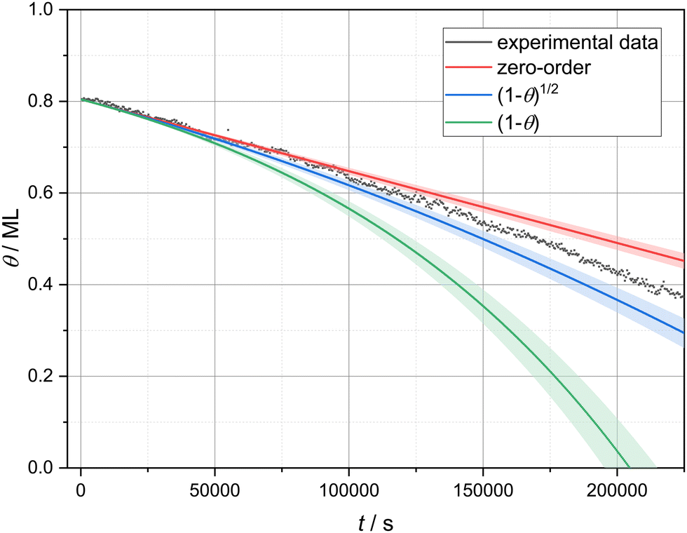 | ||
| Fig. 3 Experimental and calculated desorption curves based on three different coverage dependencies: no coverage dependence (zero-order), (1 − θ)1/2 and (1 − θ). | ||
In images from the linear desorption regime (Fig. 2b and e), the 3-nitrophenol film (white) exhibits vacancy islands (black) that are approximately triangular shaped and have two orientations. In the AFM image (b), one vacancy island of each orientation is marked by a turquoise rectangle. These vacancy islands grow through desorption. The difference image (e) shows three significant characteristics of the desorption process. First, the desorption does not occur continuously with the same speed at all borders. Instead, many molecules desorb from some borders while most borders remain unchanged. The location of these desorption events appears to be randomly distributed. Since the desorption events are much faster than the imaging speed, we see whole segments of the borders vanishing from one image to the next. Two of these desorption events are highlighted by yellow rectangles. Accordingly, it is likely that the desorption follows the terrace-ledge-kink (TLK) model:30,31 the rate-determining step is the removal of one molecule from the border of the island, which results in the formation of a double kink. The molecules adjacent to the kink have a smaller number of next neighbours and, consequently, a smaller binding energy and a higher desorption rate. In a chain-like manner, the whole border desorbs on a short timescale until no kinks are present. These findings agree with the above-made assumption of desorption from the vacancy island border. We can, thus, conclude that the specific molecular arrangement on the surface is decisive to understand the details of the desorption kinetics.
We want to note a second interesting observation. The desorption appears to occur exclusively at a specific edge in every vacancy island. Accordingly, the desorption rates from different edges of the vacancy island border differ. This finding can be explained by a tilted adsorption geometry, which could result in a strong preference of one desorption pathway. A similar situation is known for the attachment and detachment of 2,5-dihydroxybenzoic acid on calcite (10.4).32
Thirdly, and most importantly for understanding the two desorption regimes, we have analysed the widths of the molecular structures. Towards the end of the linear regime (Fig. 2c), a stripe-like appearance of the molecule-covered surface areas has established with a seemingly uniform stripe width. Coinciding with the end of the linear desorption regime, an overall change in morphology of the molecular arrangement can be observed: the interconnected molecule-covered area (Fig. 2b), which exhibited vacancy islands, gradually disconnects (Fig. 2c). This transition is a result of desorption events that disconnect the stripe network at various positions (violet boxes in Fig. 2f), leading to the qualitatively new situation of molecular islands surrounded by void surface areas.
Fast-desorption regime
From this point on and until the end of the desorption process, when it is more appropriate to talk about the desorption from molecular islands rather than from vacancy islands, we observe stripe-like islands exclusively. All islands appear to have a rather similar and uniform stripe width (Fig. 2d and g).An increased detachment rate from smaller islands has been observed in many studies.33–36 The most simple explanation is an increase of the step-edge tension for islands of shrinking diameter, i.e., of an increasing curvature. This renders smaller islands less stable as compared to larger islands. This effect alone cannot explain the rapid increase of the detachment barrier in the fast-desorption regime in our case. When the coverage decreases, we do not observe circular islands of increasing curvature but stripe-like islands instead. These islands possess a higher curvature at the island ends, which leads to a higher detachment rate at those island borders. However, the curvature along the rest of the stripe island border barely changes. Besides desorption from the island ends, we observe several island disconnection events within the remaining stripes. Three of these events are highlighted by violet rectangles in Fig. 2g. These observations prompt us to conclude that a further mechanism is at play, which results in the drastic increase of the desorption rate. A possible explanation for a drastically accelerated desorption sparing only seemingly uniform narrow islands is the existence of a long-range attraction between the molecules as will be argued in the following. As can be seen in Fig. 2g, we do not observe a gradual decrease of the island width. Instead, entire island segments vanish upon desorption. Complete desorption, however, requires the (short-lived) existence of islands with a smaller width. Since we cannot image such narrow islands, we conclude that the islands in Fig. 2d and g have reached a critical width. Islands with a width smaller than the critical island width apparently desorb on a time scale, which is much shorter than our imaging time. In the case of a long-range attraction, the critical stripe width is a measure for the length scale on which this long-ranged attraction contributes significantly to the detachment barrier. In other words, we propose the high desorption rate in the fast desorption regime is at least partly caused by straight borders of narrow islands instead of island borders of high curvature. Therefore, we have analysed the critical stripe width in high-resolution measurement series of single stripes, which are presented in the ESI† (movies: 310 K_high_resolution1–3). The three last images of one of these videos are shown in Fig. 4. These images show stripes with widths between 6 and 15 nm, which are fluctuating but do not shrink over the course of several minutes. Suddenly, between the last two images, an entire segment vanishes on a time scale much faster than our scanning capabilities allow to follow.§ Based on these measurements, we estimate a critical stripe width of around 6 nm. Islands of at least this width are desorbing slow enough to be visible in our AFM images.
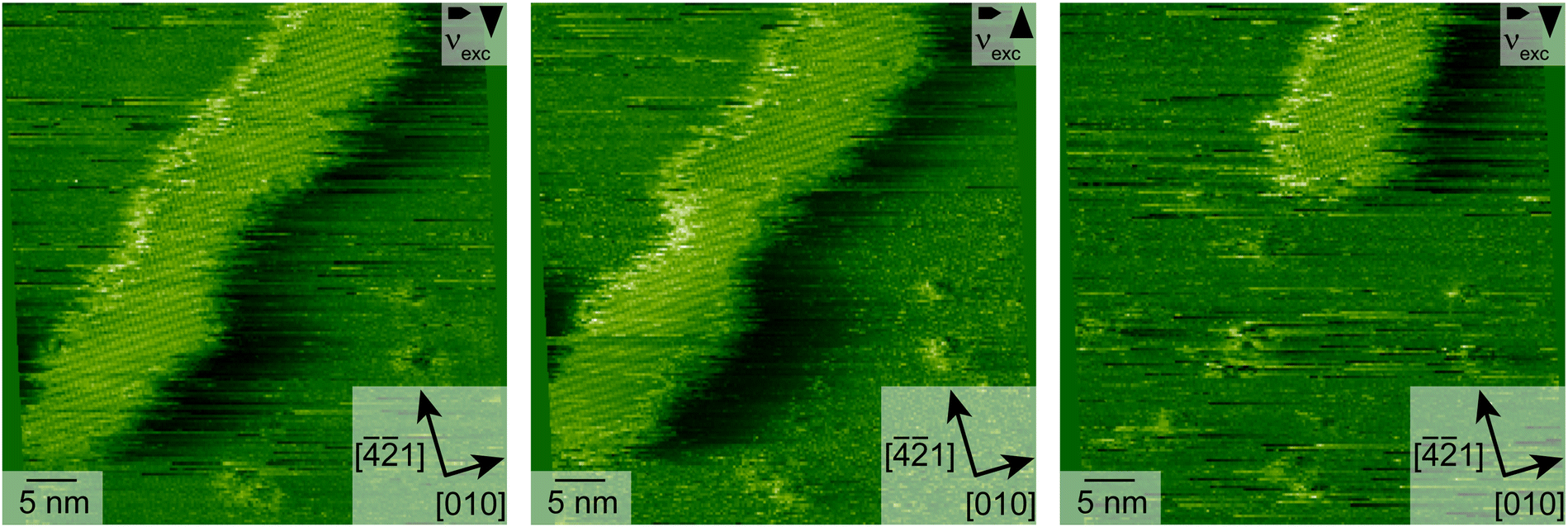 | ||
| Fig. 4 AFM images of a desorbing stripe with atomic resolution. The images of this movie series were measured with 200 × 200 pixels and a measurement time of 600 μs per pixel. | ||
A critical stripe width is a strong indication of a long-range attraction between the molecules. Due to the limited effective range of the long-range interaction, the molecules are attracted to a certain number of molecules. This number is constant as long as the stripe width is larger than the effective interaction range. When the stripe width falls below the critical width, however, the number of molecules effectively attracting each other is reduced drastically. Consequently, the detachment barrier decreases and the overall desorption rate increases. Thus, a possible explanation for the observed increase in the desorption rate is the existence of a long-range attractive interaction between the molecules. To corroborate this hypothesis, we simulated the desorption rate based on a simple numerical model. In this model, we can include the effect of a distance-dependent, radial symmetric molecule–molecule attraction on the desorption rate (see ESI† Section S4 for simulation details). For simplicity, we simulate the desorption from the perimeter of an infinite stripe, i.e., we expect zero-order desorption. Indeed, as shown in Fig. 5, the coverage as a function of time decreases linearly as long as no long-range attractions are considered. When including a long-range attraction, the coverage still decreases almost linearly at high coverages. At low coverage, however, the coverage decreases rapidly precisely as observed in our experiment. This behaviour can be understood by the fact that the contribution of the surrounding molecules to the attractive interaction with a given molecule stays almost constant as long as the island is larger than the effective range of the molecule–molecule interaction. Only when the structure width falls below a critical width, the attractive interaction decreases significantly, resulting in a rapidly increasing desorption rate.
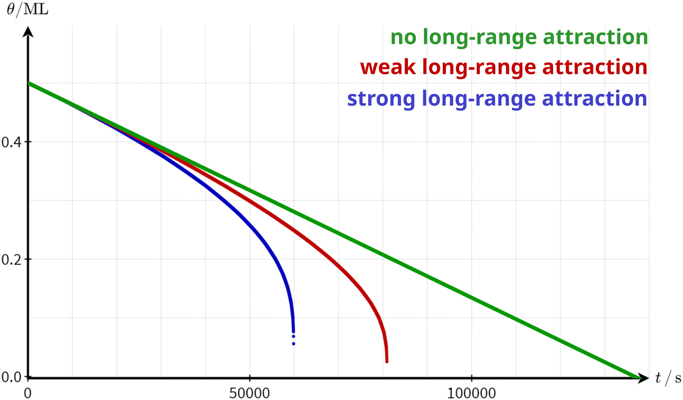 | ||
| Fig. 5 Simulated desorption curves based on the model presented in the ESI† (Section S4) with no long-range attraction (green), weak long-range attraction (red) and strong long-range attraction (blue). It is assumed that the desorption exclusively occurs from the border of an infinite stripe. The binding energy to the surface EMS was adapted to arrive at a situation where the desorption barrier at θ = 0.5 ML is the same in all three cases. | ||
While the conclusion of this simple model is independent of the nature of the molecule–molecule interaction, it is reasonable to assume dipole–dipole interactions to be at play in our specific case. This assumption is supported by our DFT calculations, revealing a strong dipole moment of a single 3-nitrophenol molecule in the gas phase. Dipoles in the x and y directions, which are defined in Fig. 1a, were calculated to be Dx = 0.78 Debye and Dy = 3.72 Debye, respectively. The modulus of the dipole is then |D| = 3.80 Debye. Even so the adsorption is expected to somewhat change this dipole, dipole–dipole interactions remain a plausible candidate for the long-range attraction, motivating the 1/r3 dependence of the interaction with the molecule–molecule distance adopted in our modeling. However, the general conclusion of this model will remain unaffected by these system-specific details even if another interaction is at play.
By fine-tuning the specific details of the investigated system, e.g., by changing the substrate or the molecular structure, it should be possible to tailor the desorption curve. For example, a molecule with a stronger dipole is not only expected to desorb at a lower rate but also change into the fast-desorption regime at a higher coverage. This is due to the higher contribution of the long-range interactions to the total desorption energy.
4 Conclusions
Isothermal desorption measurements are presented for 3-nitrophenol desorbing from the (10.4) surface of calcite. At high coverage, the desorption rate has a weak coverage dependence close to (1 − θ)1/2. This coverage dependence is indicative of desorption from the surface following detachment from the perimeter of vacancy islands. When falling below a critical island width, the desorption rate drastically increases. A possible explanation for this rapid change is the presence of a long-range attractive interaction between the adsorbates. The critical island width corresponds to the effective interaction range. When the island width falls below the critical width, the binding energy of the molecules starts to decrease. Consequently, the desorption rate rises. Based on the strong dipole moment obtained by DFT calculations for the molecule used here, the dipole–dipole interaction is a plausible candidate for a long-range attraction between the adsorbates in the specific case here. However, the effect demonstrated in this work is expected to be of general nature as long as interactions beyond next-neighbour are present.Author contributions
F. S. and L. H. carried out the experiments. F. S. analyzed the experimental data with contributions of R. B. and A. K. The DFT calculations were performed by A. F. The first version of the manuscript was written by F. S. and A. K. All authors commented and contributed to the final manuscript. All authors have given approval to the final version of the manuscript.Conflicts of interest
There are no conflicts to declare.Acknowledgements
Stimulating discussions with Hans-Jürgen Butt are gratefully acknowledged. We acknowledge financial support from the DFG through grant INST 215/552-1 FUGG.References
- K. D. Rendulic, Surf. Sci., 1992, 272, 34–44 CrossRef CAS.
- S. J. Lombardo and A. T. Bell, Surf. Sci. Rep., 1991, 13, 3–72 CrossRef.
- D. A. King, Surf. Sci., 1975, 47, 384–402 CrossRef CAS.
- G. Ertl, Angew. Chem., Int. Ed. Engl., 1990, 29, 1219–1227 CrossRef.
- R. Schlögl, Angew. Chem., Int. Ed., 2015, 54, 3465–3520 CrossRef PubMed.
- P. Stoltze, Prog. Surf. Sci., 2000, 65, 65–150 CrossRef CAS.
- T. Kawasaki, D. Sakai, H. Kishimoto, A. A. Akbar, T. Ogawa and C. Oshima, Surf. Interface Anal., 2001, 31, 126–130 CrossRef CAS.
- Y. Miyamoto, T. Nemoto, K. Yoshida, H. Kurata and S. Isoda, Jpn. J. Appl. Phys., 2004, 43, 4606–4609 CrossRef CAS.
- S. Gunther, T. O. Mentes, M. A. Nino, A. Locatelli, S. Bocklein and J. Wintterlin, Nat. Commun., 2014, 5, 3853 CrossRef CAS PubMed.
- I. Doudevski and D. K. Schwartz, Langmuir, 2000, 16, 9381–9384 CrossRef CAS.
- A. Bhattarai, U. Mazur and K. W. Hipps, J. Am. Chem. Soc., 2014, 136, 2142–2148 CrossRef CAS PubMed.
- A. Bhattarai, U. Mazur and K. W. Hipps, J. Phys. Chem. C, 2015, 119, 9386–9394 CrossRef CAS.
- Y. Fang, O. Ivasenko, A. Sanz-Matias, K. S. Mali, K. Tahara, Y. Tobe and S. de Feyter, Nanoscale, 2023, 15, 4301–4308 RSC.
- O. Ochs, N. Martsinovich, W. M. Heckl and M. Lackinger, J. Phys. Chem. Lett., 2020, 11, 7320–7326 CrossRef CAS PubMed.
- D. Nečas and P. Klapetek, Gwyddion, 2023, https://gwyddion.net/.
- T. Dickbreder, F. Sabath, L. Höltkemeier, R. Bechstein and A. Kühnle, Beilstein J. Nanotechnol., 2023, 14, 1225–1237 CrossRef CAS PubMed.
- J. Schindelin, I. Arganda-Carreras, E. Frise, V. Kaynig, M. Longair, T. Pietzsch, S. Preibisch, C. Rueden, S. Saalfeld, B. Schmid, J.-Y. Tinevez, D. J. White, V. Hartenstein, K. Eliceiri, P. Tomancak and A. Cardona, Nat. Methods, 2012, 9, 676–682 CrossRef CAS PubMed.
- H. Söngen, Kontrast: Interactive data visualization, 2023, https://soengen-dev.de/index/.
- P. Giannozzi, S. Baroni, N. Bonini, M. Calandra, R. Car, C. Cavazzoni, D. Ceresoli, G. L. Chiarotti, M. Cococcioni, I. Dabo, A. Dal Corso, S. de Gironcoli, S. Fabris, G. Fratesi, R. Gebauer, U. Gerstmann, C. Gougoussis, A. Kokalj, M. Lazzeri, L. Martin-Samos, N. Marzari, F. Mauri, R. Mazzarello, S. Paolini, A. Pasquarello, L. Paulatto, C. Sbraccia, S. Scandolo, G. Sclauzero, A. P. Seitsonen, A. Smogunov, P. Umari and R. M. Wentzcovitch, J. Phys.: Condens. Matter, 2009, 21, 395502 CrossRef PubMed.
- P. Giannozzi, O. Andreussi, T. Brumme, O. Bunau, M. Buongiorno Nardelli, M. Calandra, R. Car, C. Cavazzoni, D. Ceresoli, M. Cococcioni, N. Colonna, I. Carnimeo, A. Dal Corso, S. de Gironcoli, P. Delugas, R. A. DiStasio, A. Ferretti, A. Floris, G. Fratesi, G. Fugallo, R. Gebauer, U. Gerstmann, F. Giustino, T. Gorni, J. Jia, M. Kawamura, H.-Y. Ko, A. Kokalj, E. Küçükbenli, M. Lazzeri, M. Marsili, N. Marzari, F. Mauri, N. L. Nguyen, H.-V. Nguyen, A. Otero-de-la Roza, L. Paulatto, S. Poncé, D. Rocca, R. Sabatini, B. Santra, M. Schlipf, A. P. Seitsonen, A. Smogunov, I. Timrov, T. Thonhauser, P. Umari, N. Vast, X. Wu and S. Baroni, J. Phys.: Condens. Matter, 2017, 29, 465901 CrossRef CAS PubMed.
- P. Giannozzi, O. Baseggio, P. Bonfà, D. Brunato, R. Car, I. Carnimeo, C. Cavazzoni, S. de Gironcoli, P. Delugas, F. Ferrari Ruffino, A. Ferretti, N. Marzari, I. Timrov, A. Urru and S. Baroni, J. Chem. Phys., 2020, 152, 154105 CrossRef CAS PubMed.
- D. Vanderbilt, Phys. Rev. B: Condens. Matter Mater. Phys., 1990, 41, 7892–7895 CrossRef PubMed.
- J. P. Perdew, K. Burke and M. Ernzerhof, Phys. Rev. Lett., 1996, 77, 3865–3868 CrossRef CAS PubMed.
- S. Grimme, J. Comput. Chem., 2006, 27, 1787–1799 CrossRef CAS PubMed.
- J. Heggemann, Y. S. Ranawat, O. Krejčí, A. S. Foster and P. Rahe, J. Phys. Chem. Lett., 2023, 14, 1983–1989 CrossRef CAS PubMed.
- C. Paris, A. Floris, S. Aeschlimann, J. Neff, F. Kling, A. Kühnle and L. Kantorovich, Commun. Chem., 2018, 1, 66 CrossRef.
- K. Nagai, Vacuum, 1990, 41, 230–231 CrossRef CAS.
- H. Asada and H. Sekito, Surf. Sci., 1992, 273, 139–146 CrossRef CAS.
- H. J. Kreuzer and S. H. Payne, Surf. Sci., 1988, 200, L433–L440 CrossRef CAS.
- W. Kossel, Nachr. Ges. Wiss. Göttingen, 1927, 135–143 CAS.
- I. N. Stranski, Z. Phys. Chem., 1928, 136U, 259–278 CrossRef.
- S. Aeschlimann, J. Neff, R. Bechstein, C. Paris, A. Floris, L. Kantorovich and A. Kühnle, Adv. Mater. Interfaces, 2019, 6, 1900795 CrossRef.
- M. Giesen, Prog. Surf. Sci., 2001, 68, 1–154 CrossRef CAS.
- J. Ikonomov, C. H. Schmitz and M. Sokolowski, Phys. Rev. B: Condens. Matter Mater. Phys., 2010, 81, 195428 CrossRef.
- M. Giesen, C. Steimer and H. Ibach, Surf. Sci., 2001, 471, 80–100 CrossRef CAS.
- G. Rosenfeld, K. Morgenstern, I. Beckmann, W. Wulfhekel, E. Lægsgaard, F. Besenbacher and G. Comsa, Surf. Sci., 1998, 402–404, 401–408 CrossRef CAS.
Footnotes |
| † Electronic supplementary information (ESI) available: AFM data processing, coverage error due to lack of drift correction, isothermal desorption curves and videos at 310 K, 315 K and 330 K, a video of the difference images at 310 K, three high-resolution videos of desorbing stripes and numeric simulation of the desorption rate from an infinite stripe in the presence of long-range attraction. See DOI: https://doi.org/10.1039/d3cp05465a |
| ‡ We chose to start the fitting range at 0.826 ML rather than at the beginning of the desorption curve due to the stronger drift and less temperature accuracy at the beginning of the measurement. |
| § The scan time of one image in such a movie, including trace and retrace, is 48 s. |
| This journal is © the Owner Societies 2024 |