
Boosted reverse water-gas shift activity via exsolved Cu and Ni in silicalite-1†
Jedy
Prameswari
a,
Pei-Tung
Chou
a,
Ming-Yuan
Hung
b,
Po-Yang
Peng
c,
Ying-Rui
Lu
c,
Chi-Liang
Chen
 c,
Hong-Kang
Tian
*abd and
Yu-Chuan
Lin
*a
c,
Hong-Kang
Tian
*abd and
Yu-Chuan
Lin
*a
aDepartment of Chemical Engineering, National Cheng Kung University, Tainan 70101, Taiwan. E-mail: hktian@gs.ncku.edu.tw; yclin768@mail.ncku.edu.tw
bProgram on Smart and Sustainable Manufacturing, Academy of Innovative Semiconductor and Sustainable Manufacturing, National Cheng Kung University, Tainan 70101, Taiwan
cNational Synchrotron Radiation Research Center, Hsinchu 30076, Taiwan
dHierarchical Green-Energy Materials (Hi-GEM) Research Center, National Cheng Kung University, Tainan 70101, Taiwan
First published on 13th November 2024
Abstract
The reverse water-gas shift (RWGS) reaction offers a sustainable approach for CO2 utilization, yielding CO for vital catalytic processes. This study compares the catalytic performance of exsolved Cu- and Ni-encapsulated silicalite-1 (S-1) catalysts against those prepared by impregnation methods. Exsolved catalysts, characterized by confined metal nanoparticles and distinct surface chemistry, exhibited higher CO selectivity and lower activation energies of CO formation than their impregnated counterparts. Surface and structural analyses revealed that the exsolution process enhanced RWGS activity, driven by altered metal-support interactions and unique adsorption behaviors, offering insights for improving the efficiency of RWGS catalysis.
CO2 utilization through the reverse water-gas shift (RWGS) offers a promising approach to reducing atmospheric CO2. The RWGS reaction produces CO, a key component in catalytic processes like Fischer–Tropsch and methanol synthesis, which are essential for producing fuels and chemicals while decreasing reliance on fossil resources.1–3
Nanoparticle size is critical to CO2 hydrogenation, with smaller particles favoring RWGS and larger ones promoting methanation.4,5 Methods like impregnation and co-precipitation, often paired with treatments such as pH control, sacrificial templating, and acid treatment, aim to confine metal nanoparticles.4–7 However, these methods have limitations: pH control can yield inconsistent sizes, sacrificial templating adds waste and complexity, and acid treatment risks altering catalytic nature. The exsolution process has emerged as a promising alternative for controlling particle size, particularly in crystals like perovskites, offering unique surface chemistry and enhanced catalytic performance.8–10 Despite this potential, research on exsolution-made catalysts, especially hetero-atom encapsulation in solid solutions, remains limited.
This study investigates the exsolution of Cu- and Ni-encapsulated S-1 in RWGS catalysts synthesis. A direct comparison of RWGS-active Cu and Ni catalysts prepared by exsolved (Me@S-1-red; Me = Cu or Ni) and impregnation (Me/S-1-red) was conducted to elucidate the distinct surface chemistry of exsolved catalysts.2,11
The metal loading in the catalysts ranged from 1.8% to 3.8%, aligning closely with the target of 2% (Table S1, ESI†). XRD patterns of the precursors (Me@S-1 and Me/S-1) displayed the characteristic S-1 diffraction, with no detectable MeOx signals (Fig. S1, ESI†). H2-TPR analysis (Fig. S2, ESI†) assessed the reducibility of the precursors, guiding the exsolution conditions. The maximum rates of reduction temperature for Cu@S-1 (311 °C) and Ni@S-1 (706 °C) were higher than those of their impregnated counterparts, Cu/S-1 (276 °C) and Ni/S-1 (435 °C). Table S1 (ESI†) shows the H2 uptake and extent of reduction (EOR). Exsolved Cu@S-1 (8.3 mmol gCu−1, 66%) and Ni@S-1 (8.2 mmol gNi−1, 61.2%) had lower EOR values than their counterparts (Cu/S-1![[thin space (1/6-em)]](https://www.rsc.org/images/entities/char_2009.gif) :9.5 mmol gCu−1, 75.5%; Ni/S-1:8.6 mmol gNi−1, 64.5%, Table S1, ESI†). The reduction temperature for each precursor was selected based on the endpoint of its TPR profile: Cu@S-1 and Cu/S-1 were reduced at 500 °C to exsolve Cu cations, while Ni@S-1 was reduced at 800 °C and Ni/S-1 at 600 °C to exsolve Ni cations.
:9.5 mmol gCu−1, 75.5%; Ni/S-1:8.6 mmol gNi−1, 64.5%, Table S1, ESI†). The reduction temperature for each precursor was selected based on the endpoint of its TPR profile: Cu@S-1 and Cu/S-1 were reduced at 500 °C to exsolve Cu cations, while Ni@S-1 was reduced at 800 °C and Ni/S-1 at 600 °C to exsolve Ni cations.
The XRD patterns (Fig. S1, ESI†) of the exsolved catalysts mostly exhibited the MFI topology of S-1 structure. No diffractions of Cu and Ni species could be identified. MFI structure in Ni@S-1-red collapsed to cristobalite with little extent of MFI due to thermal-induced stress during reduction.12 The porosity is listed in Table S1 (ESI†) and N2 isotherm (Fig. S3, ESI†) showed a type I isotherm with H4 hysteresis loop. Me@S-1-red had a wide hysteresis loop (P/P0 = 0.1 to 0.9) related to slit-like pores. Me/S-1-red had a lower total surface area and pore volume but with a higher microporosity than those of Me/S-1-red. SEM images (Fig. S4, ESI†) showed coffin-shaped crystals in each catalyst, characteristic of the S-1 morphology.13 HR-TEM images (Fig. S5, ESI†) and EDS mapping (Fig. S6, ESI†) revealed uniformly dispersed Cu and Ni.
Fig. S7 (ESI†) shows the XAS fitting curves in R space for the tested catalysts, with parameters listed in Table S2 (ESI†). The first (Me–O) and second (Me–Me) shells were identified, showing similar values. For Cu catalysts, the coordination number (CN) for Cu–O was 2.3–2.6 and for Cu–Cu, 0.4–1.3; for Ni, the CN for Ni–O was 0.6–1.3 and Ni–Ni 9.7–10.3. Using the 2nd Me–Me shell, the estimated Cu0 and Ni0 sizes were approximately 2 and 32 nm respectively.14 The estimated dispersions of Cu0 and Ni0 by using Scherrer equation15 were 23.3% and 1.6%, respectively.
Fig. S8 (ESI†) shows the XPS spectra. The presence of Cu2+–O–Si and Ni2+–O–Si species could be identified solely in Cu@S-1-red and Ni@S-1-red, respectively. Fig. S9 (ESI†) shows the in situ DRIFT analysis of CO–N2 switching test at 50 °C. Cu@S-1-red and Cu/S-1-red showed Cu+-carbonyl (2116 and 2129 cm−1) caused by linearly bonded CO.16 Ni@S-1-red and Ni/S-1-red showed the formation of bridged-*CO (1880 cm−1), with a shift to higher wavenumber (1940 cm−1) for Ni@S-1-red during N2 flushing. The NH3-TPD profiles (Fig. S10, ESI†) show that only Me@S-1-red catalysts exhibit moderate acid strength, with NH3 desorption around 250 °C. Pyridine-adsorbed IR analysis (Fig. S11, ESI†) confirms these acids are Lewis acidic (1450 cm−1), absent in Me/S-1-red.
Fig. 1 shows that Cu@S-1-red achieved a higher CO2 conversion (XCO2) than Cu/S-1-red, producing only CO. Ni@S-1-red and Ni/S-1-red had similar XCO2 values at 350 and 400 °C; however, Ni@S-1-red exhibited higher RWGS conversions (XRWGS, 15.2% and 27.8%), approaching the equilibrium conversion line of RWGS (XRWGS,eq), compared to those of Ni/S-1-red (5.4% and 3.4%). The activation energy for CO formation in the exsolved catalysts is lower (34.0 kJ mol−1 for Cu@S-1-red and 37.4 kJ mol−1 for Ni@S-1-red) than in their impregnated counterparts (57.9 kJ mol−1 for Cu/S-1-red and 63.2 kJ mol−1 for Ni/S-1-red) (Fig. S12(a), ESI†). Additionally, the activation energy for CH4 formation in Ni@S-1-red is higher (126.0 kJ mol−1) than that of Ni/S-1-red (94.4 kJ mol−1) (Fig. S12(b), ESI†). The porosity (Fig. S13, ESI†) and crystallinity of the post-reaction catalysts were like their fresh forms (Fig. S14, ESI†). Fig. S15 (ESI†) presents the 100-hour durability test results. Cu@S-1-red maintained its XCO2 values of 23% to 30% with 100% CO selectivity, while Ni@S-1-red had its XCO2 values of 28% to 33% with 84.2% CO selectivity. Cu/SiO2 and Ni/SiO2 catalysts were tested for comparison (Fig. S16, ESI†), showing lower XRWGS (5.3% for Cu/SiO2 and 14.65% for Ni/SiO2 at 400 °C) than the exsolved catalysts, highlighting the superior activity of exsolved catalysts over supported catalysts and most reported in literature (Table S3, ESI†).
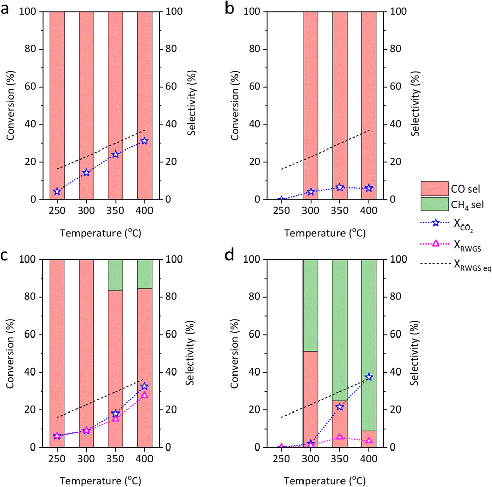 | ||
| Fig. 1 Performance of (a) Cu@S-1-red, (b) Cu/S-1-red, (c) Ni@S-1-red, and (d) Ni/S-1-red on CO2 hydrogenation. Reaction conditions: GHSV = 6000 mL gcat h−1, CO2/H2/N2= 12.5/37.5/50, 0.2 g catalyst, 1 bar. | ||
Fig. 2 presents the in situ diffuse reflectance infrared fourier transform spectroscopy (DRIFTS) analysis of exsolved Cu and Ni catalysts during CO2 and H2 switching tests. For Cu catalysts (Fig. 2(a) and S17(a)), linear *CO (2078 cm−1), bicarbonate (*HCO3, 1690 and 1343 cm−1), and bidentate carbonate (b-*CO3, 1583 cm−1) were observed in CO2. Upon switching to H2, CO(g), bridged-*CO (1955–1874 cm−1), b-*CO3, and monodentate carbonate (m-*CO3, 1453 cm−1) appeared, with m-*CO3 only present on Cu@S-1-red (Fig. 2(a)). On Ni@S-1-red, m-*CO3 (1453 cm−1) was detected in CO2 alongside *HCO3 (1679 and 1367 cm−1). After switching to H2, *HCO2 (formate, 1602 cm−1), *CHO (formyl, 1753 cm−1), and *CHx (1346 and 1302 cm−1) formed, with bridged/multi-bonded *CO found exclusively on Ni/S-1-red (Fig S17(b), ESI†), while m-*CO3 persisted on Ni@S-1-red (Fig. 2(b)).
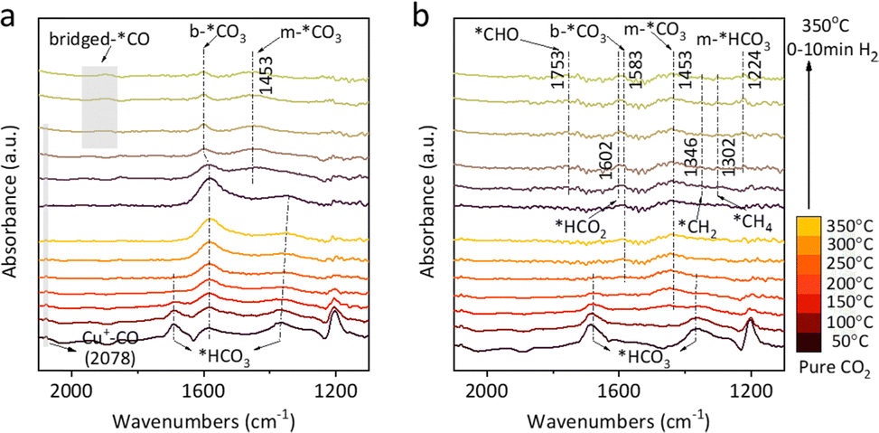 | ||
| Fig. 2 In situ DRIFTS of CO2-H2 switching test of (a) Cu@S-1-red and (b) Ni@S-1-red. | ||
In situ XAS analysis during CO2–H2 switching tests was conducted to explore the mechanism. Under CO2, the white line of Cu@S-1-red shifts toward the Cu2O reference with increasing temperature, indicating the oxidation state (δ+) increases from ∼0 to 1 (Fig. 3(a)), with a corresponding edge shift from 8979.0 eV to 8980.4 eV between 200 and 500 °C in the first derivative (Fig. S18(a), ESI†). In H2 stream, δ+ decreases from ∼1 to 0, as the white line approaches the Cu foil (Fig. 3(b)), accompanied by a downward edge shift from 8980.5 eV to 8979.3 eV (Fig. S18(b), ESI†). Ni@S-1-red showed minimal changes in CO2 and H2 environments (Fig. 3(c-d)). The white line intensity slightly increased with temperature in CO2, while in H2, it diminished, approaching the profile of Ni foil. No significant edge shift was detected (Fig. S18(c) and (d), ESI†), indicating the oxidation state of Ni in Ni@S-1-red remained nearly unchanged.
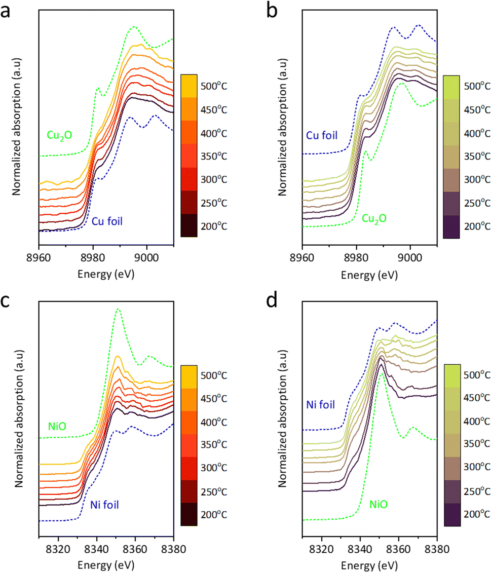 | ||
| Fig. 3 In situ XAS profile of Cu@S-1-red (a) under CO2 environment and (b) under H2 environment, and Ni@S-1-red under (c) CO2 environment and (d) H2 environment. | ||
Density Functional Theory (DFT) calculations examined CO adsorption on Cu@S-1-red and Ni@S-1-red to correlate adsorption with CO selectivity. Cu and Ni surfaces modelled the catalysts (Table S4, ESI† and Fig. 4a), considering vertical and horizontal CO configurations (Fig. S19 and S20, ESI†). After optimization, CO consistently aligned vertically, with C bonded to Cu or Ni. The lowest adsorption energies were −1.13 eV for Cu and −2.25 eV for Ni (Fig. 4b), with bond lengths of 1.94 Å (C–Ni) and 2.04 Å (C–Cu) (Fig. 4c), indicating stronger CO adsorption on Ni. Charge density difference analysis further confirmed stronger CO–Ni bonding due to greater electron transfer from Ni.
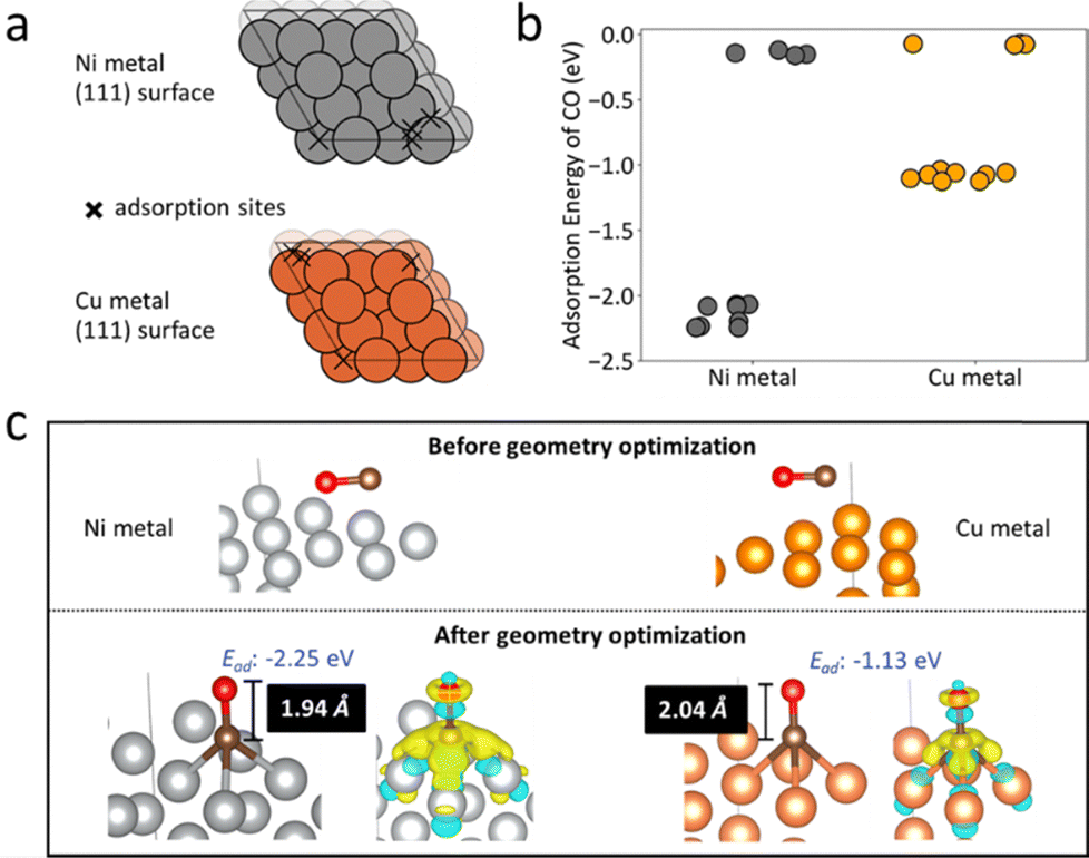 | ||
| Fig. 4 (a) Potential adsorption sites (marked by cross symbols) on the Ni and Cu (111) metal surfaces, identified using Delaunay triangulation as implemented in Pymatgen.17 The differences in adsorption site distribution between Ni and Cu are attributed to their distinct bulk lattice parameters: 3.52 Å for Ni and 3.63 Å for Cu. (b) DFT-calculated adsorption energies for a CO molecule on the Ni and Cu (111) surfaces, with each point representing a different adsorption site or CO configuration. (c) The most stable CO adsorption configurations on Ni and Cu surfaces before and after geometry optimization, showing metal-C bond lengths and charge density difference upon CO adsorption. Yellow and blue indicate regions of electron density increase and decrease, respectively. | ||
The Cu- and Ni-based catalysts showed similar physical properties elemental composition, porosity, crystallinity, and metal dispersion regardless of whether they were prepared by impregnation or exsolution. However, differences in RWGS activity revealed distinct catalytic behaviors: Me@S-1-red exhibited higher CO selectivity than that of Me/S-1-red.
Surface analysis showed that while the Mex+–O–Si phase persisted in the exsolved catalysts, the impregnated catalysts primarily featured Mex+–O species, each playing distinct roles in CO2 reduction. It was observed that highly coordinatively unsaturated sites (i.e., Ni2+–O–Si) could form m-*CO3 upon interaction with CO2, which could then be further reduced to formate and eventually to CO.18 LAS arise from the coordinatively unsaturated Mex+ species within the S-1 framework (Mex+–O–Si), and that a strong interaction between Mex+ and the support leads to a higher concentration of LAS due to the confinement effect of encapsulated Me and S-1.19,20 Moreover, the confinement effect and metal-support interactions enhance the stability of exsolved catalysts.21,22 This claim is supported by the H2-TPR results, which shows higher reduction temperature and lower EOR value of exsolved catalyst than those of the impregnated catalyst.
CO-N2 DRIFTS analysis showed that Me@S-1-red catalysts exhibited weaker CO adsorption (lower *CO wavenumbers) compared to Me/S-1-red, indicating weaker Cu+–CO (Cu@S-1-red) and bridged-*CO (Ni@S-1-red) bonding, which facilitates CO desorption.23 This weaker adsorption supports the higher CO selectivity in exsolved catalysts by promoting CO desorption and reducing the deep hydrogenation to CH4. The lower activation energy for CO formation further aligns with this behavior. Additionally, m-*CO3 and *HCO3 species – formed via CO2 adsorption on Mex+–O–Si and –OH groups, respectively24 – were unique to the exsolved catalysts, suggesting the hydroxyl-enriched S-1 support through exsolution. This finding underlined the unique surface chemistry for potential use in hydroxyl-catalyzed process like CO and alcohols oxidation.25
The in situ DRIFTS analysis of Cu@S-1-red during CO2–H2 switching showed that m-*CO3 decomposed to produce CO, indicating a redox mechanism. Here, CO2 chemisorbs onto oxygen vacancies (Ov), causing surface oxidation. Consistently, in situ XAS spectra show an edge shift in Cu@S-1-red from 0 to 1 under CO2 (signifying oxidation) and returns from 1 to 0 in H2 (reflecting reduction). In contrast, Ni@S-1-red promotes the conversion of m-*CO3 to m-*HCO3via surface hydrogen, suggesting an associative mechanism. The lack of significant XAS edge shifts and unchanged DRIFTS signals during CO2 flushing support this pathway. While Ni catalysts are often linked to the redox-driven RWGS,26 the distinct redox (Cu@S-1-red) and associative (Ni@S-1-red) mechanisms observed here merit further study.
DFT calculations further illustrate the differences in RWGS performance between Cu and Ni catalysts. Our previous study,18 demonstrated that weaker CO adsorption, indicated by more positive adsorption energy, enhances CO selectivity by favoring desorption over further reduction to CH4. The observed electron transfer differences arise from greater π-backdonation from Cu compared to Ni, leading to stronger CO adsorption on Ni and resulting in CH4 as a byproduct.
In conclusion, we demonstrated the distinctive advantage of exsolution in preparing Cu and Ni catalysts. Despite comparable physical properties, i.e., active metal dispersion, they exhibited different performance and reaction pathways in the RWGS reaction. Notably, the exsolution process generates unique Mex+–O–Si species that promote the m-CO3* route, absent in impregnated catalysts. These findings highlight the potential of exsolution-induced confinement effects in tuning RWGS reaction mechanisms.
J. P.: Investigation, validation, and writing – original draft; P.-T. C.: Investigation and validation; M.-Y. H.: DFT calculation; P.-Y. P.: Formal analysis and validation; Y.-R. L.: Investigation and data curation; C.-L. C.: Data curation and resources; H.-K. T.: DFT calculation, validation, and writing – original draft; Y.-C. L.: Supervision, funding acquisition, and writing – review & editing.
This study was supported by the National Science and Technology Council (Projects 110-2222-E-006-014-MY3, 112-2923-E-006-004, 113-2221-E-006-023-MY3, and 113-2221-E-006-199-MY3) and the Higher Education Sprout Project, Ministry of Education, to the Headquarters of University Advancement, National Cheng Kung University (NCKU). The authors thank the TPS 32A beamline staffs at NSRRC, Taiwan, for their supports. We also acknowledge the use of XPS (ESCA003700) and HR-TEM (EM000800) from NSTC 113-2740-M-006-002 at the Core Facility Center, and the computational and storage resources provided by the National Center for High-performance Computing (NCHC) and the Miin Wu School of Computing, NCKU.
Data availability
The data supporting this article have been included as part of the ESI.†Conflicts of interest
There are no conflicts to declare.Notes and references
- J. Zhu, G. Zhang, W. Li, X. Zhang, F. Ding, C. Song and X. Guo, ACS Catal., 2020, 10, 7424–7433 CrossRef CAS.
- A. Kumar, A. A. A. Mohammed, M. A. H. S. Saad and M. J. Al-Marri, Int. J. Energy Res., 2022, 46, 441–451 CrossRef CAS.
- C. Zhang, R. Zhang, Y. Liu, X. Wu, H. Wang, Q. Ge and X. Zhu, ChemCatChem, 2023, 15, e202201284 CrossRef CAS.
- C.-S. Chen, C. S. Budi, H.-C. Wu, D. Saikia and H.-M. Kao, ACS Catal., 2017, 7, 8367–8381 CrossRef CAS.
- J. F. M. Simons, T. J. de Heer, R. C. J. van de Poll, V. Muravev, N. Kosinov and E. J. M. Hensen, J. Am. Chem. Soc., 2023, 145, 20289–20301 CrossRef CAS PubMed.
- C. Vogt, E. Groeneveld, G. Kamsma, M. Nachtegaal, L. Lu, C. J. Kiely, P. H. Berben, F. Meirer and B. M. Weckhuysen, Nat. Catal., 2018, 1, 127–134 CrossRef CAS.
- D. Wang, Z. Yuan, X. Wu, W. Xiong, J. Ding, Z. Zhang and W. Huang, ACS Catal., 2023, 13, 7132–7138 CrossRef CAS.
- H. S. Lim, M. Lee, Y. Kim, D. Kang and J. W. Lee, Int. J. Hydrogen Energy, 2021, 46, 15497–15506 CrossRef CAS.
- L. Lindenthal, J. Popovic, R. Rameshan, J. Huber, F. Schrenk, T. Ruh, A. Nenning, S. Löffler, A. K. Opitz and C. Rameshan, Appl. Catal., B, 2021, 292, 120183 CrossRef CAS.
- F. Orsini, D. Ferrero, S. F. Cannone, M. Santarelli, A. Felli, M. Boaro, C. de Leitenburg, A. Trovarelli, J. Llorca, G. Dimitrakopoulos and A. F. Ghoniem, Chem. Eng. J., 2023, 475, 146083 CrossRef CAS.
- A. M. Bahmanpour, F. Héroguel, M. Kılıç, C. J. Baranowski, L. Artiglia, U. Röthlisberger, J. S. Luterbacher and O. Kröcher, ACS Catal., 2019, 9, 6243–6251 CrossRef CAS.
- D. S. Bhange and V. Ramaswamy, Mater. Res. Bull., 2007, 42, 851–860 CrossRef CAS.
- S. Xu, T. J. A. Slater, H. Huang, Y. Zhou, Y. Jiao, C. M. A. Parlett, S. Guan, S. Chansai, S. Xu, X. Wang, C. Hardacre and X. Fan, Chem. Eng. J., 2022, 446, 137439 CrossRef CAS.
- A. Jentys, Phys. Chem. Chem. Phys., 1999, 1, 4059–4063 RSC.
- A. Borodziński and M. Bonarowska, Langmuir, 1997, 13, 5613–5620 CrossRef.
- M. D'Andria, F. Krumeich, Z. Yao, F. R. Wang and A. T. Güntner, Adv. Sci., 2024, 11, 2308224 CrossRef PubMed.
- S. P. Ong, W. D. Richards, A. Jain, G. Hautier, M. Kocher, S. Cholia, D. Gunter, V. L. Chevrier, K. A. Persson and G. Ceder, Comput. Mater. Sci., 2013, 68, 314–319 CrossRef CAS.
- C.-H. Chen, H.-K. Chen, W.-H. Huang, C.-L. Chen, K. Choojun, T. Sooknoi, H.-K. Tian and Y.-C. Lin, Green Chem., 2023, 25, 7582–7597 RSC.
- J. Tan, X. Xia, J. Cui, W. Yan, Z. Jiang and Y. Zhao, J. Phys. Chem. C, 2019, 123, 9779–9787 CrossRef CAS.
- M. U. Rehman, H. Wang, Q. Han, Y. Shen, L. Yang, X. Lu, X. Guo, N. Ji, S. Wang, Y. Xu and Y. Zhao, Fuel, 2024, 378, 132891 CrossRef CAS.
- N. Wang, Q. Sun and J. Yu, Adv. Mater., 2019, 31, 1803966 CrossRef PubMed.
- Q. Sun, N. Wang and J. Yu, Adv. Mater., 2021, 33, 2104442 CrossRef CAS PubMed.
- J. C. Campuzano and R. G. Greenler, Surf. Sci., 1979, 83, 301–312 CrossRef CAS.
- P. Rzepka, Z. Bacsik, A. J. Pell, N. Hedin and A. Jaworski, J. Phys. Chem. C, 2019, 123, 21497–21503 CrossRef CAS.
- M. S. Ide and R. J. Davis, Acc. Chem. Res., 2014, 47, 825–833 CrossRef CAS PubMed.
- K.-J. Lee, Y. Ye, H. Su, B. S. Mun and E. J. Crumlin, ACS Catal., 2023, 13, 9041–9050 CrossRef CAS.
Footnote |
| † Electronic supplementary information (ESI) available: Experimental details, characterization data. See DOI: https://doi.org/10.1039/d4cc04964k |
| This journal is © The Royal Society of Chemistry 2024 |