DOI:
10.1039/D4CC02687J
(Communication)
Chem. Commun., 2024,
60, 11275-11278
Improvements in the evaluation of electrocatalytic ammonia oxidation reactions†
Received
3rd June 2024
, Accepted 9th August 2024
First published on 12th August 2024
Abstract
For a reliable evaluation of the electrocatalytic ammonia oxidation reaction (EAOR), we revised the standard electrode potentials in both aqueous and nonaqueous electrolytes using the solvation energies of ammonia. Moreover, we developed an improved assessment protocol for EAOR systems, particularly for those employing nonaqueous electrolytes and/or nitrogen-containing materials.
The electrocatalytic ammonia oxidation reaction (EAOR) holds promising applications in the energy conversion field due to ultrahigh hydrogen content (17.7 wt%), zero carbon content, and the ease of liquefaction of ammonia.1–3 Ideally, ammonia is oxidized to N2 at the anode and water is reduced to H2 at the cathode, following the reactions eqn (1)–(3). Based on the change in the standard Gibbs free energy (16.407 kJ mol−1) for the overall reaction (eqn (3)), only 0.06 V is required for ammonia electrolysis, representing up to 95% energy savings compared to water electrolysis.4 However, practical applications of the EAOR have yet to be realized due to large overpotentials, sluggish reaction kinetics, and poor stability.1–3,5–7| | | Anode: N2(g) + 6H2O(l) + 6e− ↔ 2NH3(g) + 6OH−(aq) E0 = −0.77 V vs. SHE | (1) |
| | | Cathode: 6H2O(l) + 6e− ↔ 6OH−(aq) + 3H2(g) E0 = −0.83 V vs. SHE | (2) |
| | | Overall: 2NH3(g) ↔ N2(g) + 3H2(g) E0 = −0.06 V | (3) |
There are two primary types of EAOR electrocatalysts: noble and non-noble metal-based catalysts. To date, Pt-based catalysts exhibit the best EAOR activity, although their overpotentials remain above 0.5 V, and they are susceptible to poisoning and deactivation.1–3 Efforts to enhance their EAOR performance through regulation of the composition and nanostructure have resulted in significant improvements in current density but limited effects on overpotential and stability.8–10 In contrast, non-noble metal-based electrocatalysts, which are abundant and offer reduced cost and improved durability, generally suffer from higher overpotentials (>1.5 V) and serious side reactions, inducing considerable by-products and electrode corrosion.11–16 Therefore, the development of new catalysts that are low-cost, highly active, and exceptionally stable is urgent. Simulation studies predict that introduction of nitrogen (N) can alter the binding energy between the metal and intermediates, potentially improving EAOR performance.17,18 Experimentally, Little et al. reported the first nitride EAOR electrocatalyst (FeNx), which exhibited EAOR performance comparable to Pt under the same testing conditions (onset potential, 1.15 V vs. NHE).19 Subsequently, He et al. reported another nitride EAOR electrocatalyst, NiCo2N nanosheets, with an onset potential (0.55 V vs. NHE) even lower than that of the Pt/C electrocatalyst.20 These studies suggest great potential for nitride catalysts in the EAOR.
The electrolyte also plays a crucial role in EAOR, yet few studies have focused on this aspect. Alkaline aqueous electrolytes are commonly used in EAOR studies due to their high ionic conductivity, low toxicity, and ease of handling. However, as noted, the enhancement of EAOR performance with aqueous electrolytes is limited. Thus, applying the EAOR in non-aqueous electrolytes could be a viable alternative. To date, only a few studies have investigated non-aqueous electrolytes, typically involving solvents such as ammonia-saturated acetonitrile or N,N-dimethylformamide, with solutes like KPF6 or tetrabutylammonium salts.6,20–24 Using an ammonia-saturated acetonitrile electrolyte with 0.06 M nBu4NBF4, Li Xiao et al. reported the absence of poisoning for the Pt catalyst, a significant departure from results in aqueous electrolytes.24 Recently, remarkable enhancements in both onset potential and durability of the EAOR were reported using ammonia-saturated 0.1 M KPF6 acetonitrile electrolyte.20
These reports on nitride catalysts and non-aqueous electrolytes are promising. However, these new systems, involving either new nitrogen sources other than ammonia or uncertain effects on the counter electrode, pose challenges for evaluating EAOR activity. Additionally, the literature potentials as shown in eqn (1)–(3)1–4 were based on data of free energies of formation of NH3 gas, which differs from the actual state of NH3 in the aqueous and nonaqueous electrolytes. In this work, we first recalculate the standard electrode potentials of the EAOR by considering the solvation energies of NH3 in the electrolytes. We then present two cases to elucidate the key points for attention in experimentally evaluating the EAOR systems that utilize nitride materials and non-aqueous electrolytes. The revised standard electrode potentials and improved protocol would help to evaluate the EAOR activity and performances more reliably, accelerating the development of high-performance catalysts and electrolytes for EAOR technologies.
For a practical EAOR system using either an aqueous electrolyte or nonaqueous electrolyte, NH3 exists in the liquid state by dissolving in the media. To obtain reliable standard electrode potentials, the solvation energies of NH3 in the electrolytes need to be considered. For a dilute electrolyte, this solvation energy could be approximately equal to that of NH3 in the pure solvent. In this work, we adopted the widely studied water and acetonitrile (AN) as the solvents representative for aqueous and nonaqueous electrolyte, respectively. According to the reported solvation energies of NH3(g) in water (eqn (4)) and AN (eqn (5)) and of NH4+(aq) in AN (eqn (6)),25 the standard electrode potentials of the EAOR in aqueous and AN-based nonaqueous electrolytes can be recalculated (see the ESI† for calculation details). In the nonaqueous system, the pathway of the EAOR via NH4+ was chosen based on the previous studies.22–24 The obtained results are listed in eqn (7)–(12). For the aqueous system, the anode potential was revised from 0.77 V vs. SHE to 0.736 V vs. SHE, and the overall voltage was revised from −0.06 to −0.092 V. For the AN-based nonaqueous system, the anode and cathode potentials and the overall voltage were determined, which are 0.406 V vs. NHE, −0.469 V vs. NHE, and −0.063 V, respectively. Due to a small change in the thermodynamics of the overall reaction, the overall voltage difference between the aqueous and nonaqueous systems is very small (−0.092 vs. −0.06 V). However, we noticed remarkable differences in the anode/cathode potential for these two systems, indicating that the solvation energy has a profound influence on the electrode potentials. Hence, these revised standard electrode potentials provide a more accurate benchmark for EAOR evaluation.
| | | NH3(g; 1 atm) ↔ NH3(aq; 1 M) ΔG0 = −10.090 kJ mol−1 | (4) |
| | | NH3(g; 1 atm) ↔ NH3(AN; 1 M) ΔG0 = −1.717 kJ mol−1 | (5) |
| | | 6NH4+(aq) ↔ 6NH4+(AN) ΔG0 = 95.96 kJ mol−1 | (6) |
In aqueous electrolyte (298.15 K):
| | | Anode: N2(g) + 6H2O(l) + 6e− ↔ 2NH3(aq) + 6OH−(aq) E0 = −0.736 V vs. SHE | (7) |
| | | Cathode: 6H2O(l) + 6e− ↔ 6OH−(aq) + 3H2(g) E0 = −0.828 V vs. SHE | (8) |
| | | Overall: 2NH3(aq) ↔N2(g) + 3H2(g) E = −0.092 V | (9) |
In non-aqueous electrolyte (298.15 K):
| | | Anode: 1/2 N2(g) + 3NH4+(AN) + 3e− ↔ 4NH3(AN) E0 = –0.406 V vs. NHE | (10) |
| | | Cathode: 3NH4+(AN) + 3e− ↔ 3NH3(AN) + 3/2H2(g) E0 = −0.469 V vs. NHE | (11) |
| | | Overall: NH3(AN) ↔ 1/2 N2(g) + 3/2H2(g) E = −0.063 V | (12) |
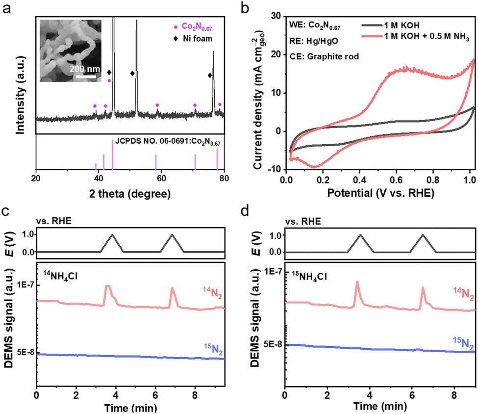
Next, we present two cases for EAOR measurements. The first one applies a cobalt nitride material in conventional alkaline aqueous electrolytes. The cobalt nitride was prepared via a two-step process of hydrothermal synthesis and nitridation, using nickel foam as the substrate. According to scanning electron microscopy (SEM) and X-ray diffraction (XRD) characterization studies, the as-prepared material exhibited a chain-like morphology with a possible phase composition of Co2N0.67 (Fig. 1a). Cyclic voltammetry (CV) tests were conducted in 1 M KOH aqueous electrolytes with and without ammonia to preliminarily assess the EAOR activity, using a three-electrode cell with the nitride material, graphite rod, and Hg/HgO as the working, counter, and reference electrodes, respectively (Fig. 1b). In 1 M KOH electrolyte, no current density was observed in the CV scans between 0 and 1.0 V vs. RHE. By contrast, in 1 M KOH + 1 M NH3 electrolyte, anodic current density appeared at approximately 0.3 V vs. RHE and reached a peak of about 15.0 mA cm−2 at around 0.6 V vs. RHE. As the nickel foam substrate makes no contribution to the anodic current density (see Fig. S2, ESI†), these results suggest that the as-prepared nitride material would exhibit good EAOR activity with an ultra-low onset potential superior to that of Pt-based catalysts. Subsequently, the gas products were analyzed using differential electrochemical mass spectrometry (DEMS). N2 gas was detected (Fig. 1c), further supporting the preliminary EAOR assessment based on the CV results.
 |
| | Fig. 1 EAOR measurements of a cobalt nitride material in aqueous electrolytes. (a) XRD pattern of as-prepared cobalt nitride material. The inset shows SEM image of the material. (b) CV curves of as-prepared cobalt nitride material in the aqueous electrolytes of 1 M KOH and 1 M KOH + 0.5 M NH3. (c) and (d) DEMS analysis of gas products at the anode in the electrolytes of 1 M KOH + 14NH4Cl (c) and 1 M KOH + 15NH4Cl (d). The scan rate is 10 mV s−1. The potential is converted according to ERHE = EHg/HgO + 0.9004 V. | |
Given that the nitride material contains nitrogen, which may contribute to the formation of N2 gas, we conducted an isotope measurement using 15NH4Cl as the ammonia source to identify the nitrogen origin of the N2 gas product (see Fig. 1c and Fig. S1, ESI†). Surprisingly, no 15N2 but solely 14N2 gas was detected (Fig. 1c), indicating that all the nitrogen in the produced N2 came from the nitride material rather than the ammonia. This result contradicts the CV and DEMS results, unambiguously clarifying that the as-prepared nitride material is not a genuine EAOR catalyst. Thus, we conclude that the as-prepared nitride was unstable during the CV test and underwent an oxidation reaction to form N2, possibly induced by the ammonia in the electrolyte. The mechanism is unclear and requires further study. Nevertheless, for systems containing new nitrogen sources besides ammonia, it is necessary to conduct isotope measurements to identify the origin of nitrogen oxidation.
The second case explores the application of nonaqueous electrolytes for the EAOR. The nonaqueous electrolyte used in this study is 0.1 M tetra-n-butylammonium hexafluorophosphate (nBu4NPF6) dissolving in ammonia-saturated AN with a water content of <50 ppm. The EAOR was initially tested in a three-electrode cell with a Pt wire, Pt mesh, and Ag0/+ (0.01 M AgNO3 in AN) serving as the working, counter, and reference electrodes, respectively. Fig. 2a shows the CV curves of Pt in the nonaqueous electrolytes with and without ammonia. The anodic current density started at approximately 1.06 V vs. NHE (1.0 mA cm−2) and reached 5.0 mA cm−2 at around 1.31 V vs. NHE. Consistent with literature reports,6,20–24 no poisoning phenomenon was observed for Pt in the nonaqueous electrolyte, demonstrating a different behavior compared to that in the aqueous electrolyte. Despite this promising result, the overpotential of Pt in the nonaqueous system is about 0.65 V, which is slightly higher than that in the aqueous system. Additionally, very little N2 was detected compared to H2 (see Fig. 2b), suggesting complex reactions in the nonaqueous system. To exclude any potential shift caused by the reference electrode, we conducted ammonia electrolysis in a two-electrode cell. The onset potential reached an incredibly high value of approximately 3.2 V at 1.0 mA cm−2 (Fig. 2c), indicating an even higher overpotential on the cathode. We also tested the as-prepared cobalt nitride in the AN-based electrolyte and obtained similar results (see Fig. S3, ESI†).
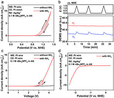 |
| | Fig. 2 EAOR measurements of Pt in nonaqueous electrolytes. (a) CV curves of Pt in the nonaqueous electrolytes of 0.1 M nBu4NPF6 in acetonitrile with/without ammonia. (b) On line MS analysis of gas products during the EAOR test. (c) CV curves of ammonia electrolysis in a two-electrode cell. (d) HER of Pt in the nonaqueous electrolyte. The scan rate is 20 mV s−1. The potential is converted according to ENHE = EAg0/+ +ΔE(Ag0/+![[thin space (1/6-em)]](https://www.rsc.org/images/entities/char_2009.gif) −Fc0/+) + 0.400 V = EAg0/+ + 0.489 V. −Fc0/+) + 0.400 V = EAg0/+ + 0.489 V. | |
In the aqueous system, the study of hydrogen evolution reaction (HER) at the cathode is usually negligible due to the very low overpotential (less than 0.10 V at 10 mA cm−2) compared to that of the EAOR at the anode.26 In the nonaqueous system, the overpotential on the cathode could become very large, as deduced from the test in the two-electrode cell. Thus, the study of the HER at the cathode should not be ignored, yet previous work using nonaqueous electrolytes has rarely paid attention to it. In this work, we applied a negative scan between 0.3 and −2.4 V vs. NHE to study the HER on Pt in the three-electrode cell. As shown in Fig. 2d, the onset potential for the HER was about −1.83 V vs. NHE at 1.0 mA cm−2, corresponding to an overpotential of 1.36 V for the HER, which is dramatically higher than that in aqueous electrolytes. Moreover, at such low potentials, the electrolyte may undergo some reduction reactions accompanied by the HER. And the reduction products left in the electrolyte may cross over to the anode and undergo oxidation reactions without N2 formation. This assumption provides a possible explanation for the observed phenomenon of much H2 being generated on the cathode but little N2 on the anode. Meanwhile, the reductive decomposition of electrolyte may produce a passivation film on the electrode surface accounting for the observed large overpotential for the HER, similar to the passivation of electrodes in the lithium and sodium batteries.27 Because the practical application of the EAOR requires a minimal overpotential of overall reaction, a comprehensive study on both the anode and cathode is necessary for an accurate assessment of the system when using nonaqueous electrolytes for the EAOR.
Clearly, the above results indicate that conventional measurements of CV plus MS on the anode are insufficient to accurately evaluate EAOR performance in some cases. Hence, we propose a recommended protocol for evaluating the EAOR in the form of a flowchart (Fig. 3). In systems containing new nitrogen sources besides NH3, the generated N2 may not be directly derived from NH3. Conventional measurements, such as CV, MS, and ion chromatography (IC), cannot identify the nitrogen origin for N2, which may result in a misjudgment of EAOR activity. Therefore, isotope measurements using the 15NH3 source are necessary to assess whether the studied system exhibits true EAOR activity or not. In systems using nonaqueous electrolytes, measurements on the anode alone are insufficient because the overpotential at the cathode may be even larger. If the actual operating potentials exceed the electrochemical stability window of the electrolyte, side reactions can occur between the anode and cathode instead of the EAOR. Thus, both the anode and cathode need to be carefully studied in nonaqueous systems. Moreover, we recommend examining the onset potential in a full cell (two-electrode cell), which offers two benefits: (1) a more reliable parameter to reflect the kinetic barrier encountered by the overall reaction, not just by the anode; and (2) allowing direct comparison of the overall overpotential between the nonaqueous and aqueous systems.
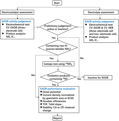 |
| | Fig. 3 A recommended protocol for the evaluation of the EAOR. | |
For an effective comparison of EAOR performances under different testing conditions, it is recommended that the current density be normalized by the electrode geometric area (mA cmgeo−2) or electrochemically active surface area (mA cmECSA−2), and that the potential be converted to a standard one vs. RHE or NHE. The onset potential should be clearly defined with the corresponding current density. For steady-state tests using chronoamperometry (CA) and chronopotentiometry (CP), the corresponding current and voltage should be provided. Besides, for an EAOR system with poor stability, special care of the compositional/structural change of the material is required to exclude the pseudo catalysis caused by a non-faradaic reaction between the material and ammonia.
In summary, we recalculated the standard electrode potentials of the EAOR in the aqueous and AN-based nonaqueous electrolytes by considering the solvation energies of NH3(g) in the solvent for the first time. These revised standard electrode potentials provide a more accurate benchmark for evaluating the overpotential of EAOR. Moreover, we found that conventional measurements cannot reliably assess the activity of EAOR systems employing nitride materials and/or non-aqueous electrolytes. We recommend a modified protocol for these cases: for systems containing new nitrogen sources other than ammonia, isotope experiments are necessary to verify the nitrogen origin of electro-oxidation; for systems using non-aqueous electrolytes, the impact of the electrolyte on both the anode and cathode should be carefully investigated. We hope that these revised standard electrode potentials and improved protocols will accelerate the development of high-performance EAOR catalysts and electrolytes, thereby promoting the practical application of EAOR technologies.
This work was supported by Westlake Education Foundation. The authors thank Dr Qike Jiang at the Instrumentation and Service Center for Physical Science for characterization support.
Data availability
The data supporting this article have been included as part of the ESI.†
Conflicts of interest
The authors declare no conflict of interest.
References
- G. Jeerh,
et al.
, J. Mater. Chem. A, 2021, 9, 727–752 RSC.
- D. T. Tran,
et al.
, Nano Energy, 2022, 94, 106929 CrossRef CAS.
- Y. Tian,
et al.
, Small Struct., 2023, 4, 2200266 CrossRef CAS.
- E. L. Simons,
et al.
, J. Electrochem. Soc., 1969, 116, 556–561 CrossRef CAS.
- Y. Katayama,
et al.
, ACS Catal., 2016, 6, 2026–2034 CrossRef CAS.
- Z. J. Schiffer,
et al.
, J. Phys. Chem. C, 2019, 123, 9713–9720 CrossRef CAS.
- Y. Jin,
et al.
, Chem. Commun., 2022, 58, 10631–10634 RSC.
- Y. Li,
et al.
, Energy Environ. Sci., 2021, 14, 1449–1460 RSC.
- Z.-F. Li,
et al.
, Electrochim. Acta, 2017, 228, 351–360 CrossRef CAS.
- Y. Yang,
et al.
, J. Mater. Chem. A, 2021, 9, 11571–11579 RSC.
- W. Xu,
et al.
, Appl. Catal., B, 2018, 237, 1101–1109 CrossRef CAS.
- J. Huang,
et al.
, ACS Appl. Energy Mater., 2020, 3, 4108–4113 CrossRef CAS.
- R. Wang,
et al.
, Chem. Eng. J., 2021, 404, 132579 Search PubMed.
- J. Huang,
et al.
, Nano Res., 2022, 15, 5987–5994 CrossRef CAS.
- H. Zhang,
et al.
, Chem. Eng. J., 2023, 452, 139582 CrossRef CAS.
- Y. Jin,
et al.
, Chem. Commun., 2024, 60, 1104–1107 RSC.
- J. Hao,
et al.
, ACS Catal., 2017, 7, 4214–4220 CrossRef CAS.
- J. K. Nørskov,
et al.
, Proc. Natl. Acad. Sci. U. S. A., 2011, 108, 937–943 CrossRef PubMed.
- D. J. Little,
et al.
, ACS Appl. Mater. Interfaces, 2017, 9, 16228–16235 CrossRef CAS PubMed.
- M. C. Buzzeo,
et al.
, Electroanalysis, 2004, 16, 888–896 CrossRef CAS.
- W. Peng,
et al.
, J. Phys. Chem. C, 2011, 115, 23050–23056 CrossRef CAS.
- D. J. Little,
et al.
, Energy Environ. Sci., 2015, 8, 2775–2781 RSC.
- S. He,
et al.
, Nano Energy, 2021, 80, 105528 CrossRef CAS.
- S. He,
et al.
, Nano Res., 2021, 15, 4785–4791 CrossRef.
- B. M. Lindley,
et al.
, ACS Energy Lett., 2016, 1, 698–704 CrossRef CAS.
- N. Mahmood,
et al.
, Adv. Sci., 2017, 5, 1700464 CrossRef PubMed.
- J. Wang,
et al.
, Nat. Energy, 2017, 3, 22–29 CrossRef.
|
| This journal is © The Royal Society of Chemistry 2024 |

 bce,
Yang
Liu‡
bce,
Yang
Liu‡