 Open Access Article
Creative Commons Attribution 3.0 Unported Licence
Exploring the full range of N⋯I⋯X halogen-bonding interactions within a single compound using pressure†
Richard H.
Jones
 *a,
Craig L.
Bull
 bc,
Nicholas P.
Funnell
 b,
Kevin S.
Knight
 de and
William G.
Marshall‡
b
aSchool of Chemical and Physical Sciences, Lennard-Jones Building, Keele University, Keele, Staffs ST5 5BG, UK. E-mail: r.h.jones@keele.ac.uk
bISIS Neutron and Muon Source, Rutherford Appleton Laboratory, Didcot, Oxon OX11 0QX, UK
cSchool of Chemistry, University of Edinburgh, David Brewster Road, Edinburgh EH9 3FJ, Scotland, UK
dDepartment of Earth Sciences, University College London, Gower Street, London WC1E 6BT, UK
eDepartment of Earth Sciences, The Natural History Museum, Cromwell Road, SW7 5BD, UK
First published on 27th March 2024
Abstract
The response of the trimethylammonium–iodinechloride and diiodide (TMA–ICl/I2) crystal structures have been examined under high pressure using neutron powder diffraction. TMA–ICl exhibits impressive pressure-driven electronic flexibility, where the N⋯I–Cl interactions progressively encompass all the distances represented in analogous structures recorded in the Cambridge Structural Database. Comparison with the TMA–I2 complex reveals that this flexibility is owed to the electronegativity of the chlorine atom which induces increased distortion of the iodine electron cloud. This structural flexibility may be influential in the future design of functional molecular materials.
Halogen bonds are an important class of intermolecular sigma hole interaction,1 which also include chalogen,2 pnictogen,3 and tetrel4 bonds which have previously been categorized as ‘secondary’ bonds.5 Though hydrogen bonds are often considered the canonical intermolecular interaction in the organic solid state, it has long been recognised that these other secondary interactions can compete with hydrogen bonds in the stabilisation of crystal structures,6–8 but also work in conjunction to form self-assembled porous structures.9 There has since been a rapidly-growing appreciation of the use of halogen bonds as an important tool in crystal engineering, leading to a substantial collection of review articles—these have, themselves, been usefully summarised in a single recent review.10 Interest in halogen bonds has now progressed to wider use in materials science,11 surfaces,12 and nanostructures.13
Due to their historic prominence, our understanding of hydrogen bonds has benefited from exhaustive study across a wide range of different chemical environments and structural response to external stimuli.14 The application of pressure in particular has been a powerful means for tuning interaction strengths and inducing pronounced structural change—in some cases even trapping destabilising hydrogen bond interactions.15 There are 2200 structures in the Cambridge Structural Database (CSD) that feature O/N⋯H bonding under pressure, compared with just 635 structures that cover a much broader chemical landscape with X⋯Y interactions where X = any halogen, and Y = N/O/F/S/Cl/Br/I.§ As such, there is less recorded structural information on halogen bond interactions for crystal engineers to draw from. The substantially wider chemical parameter space involved in halogen bonding presents a greater challenge for fully mapping out interaction strength/trends with pressure—the geometric limits of halogen bonding are not as well established as for hydrogen bonding.
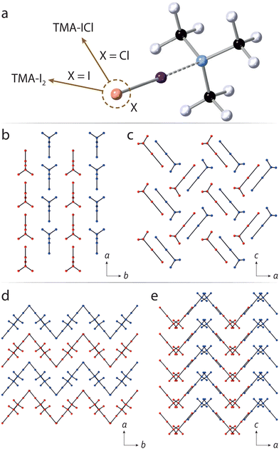
There is a great deal of flexibility in the bonding environment around halogen atoms, and can be exploited using high pressure, for example in tuning optical properties via halogen bond-driven charge transfer.16 This is particularly true of halogen bonding interactions involving the chemically-softer I and Br atoms, which contrasts the case in hydrogen bonding where O–H, and N–H covalent bond distances are constrained to a relatively narrow range. The very different X-ray scattering factors between halogen/non-halogen atoms (in organic substances) means that data sensitivity is dominated by the former. Neutron diffraction offers a clear advantage in that there is greater parity in scattering power across the majority of atoms. We have previously investigated neutron structural studies of halogen-bonded systems at ambient pressure and,17–19 more recently, reported one of very few neutron-determined structures under pressure.20 In this study, we have sought to explore a halogen-bonded system which exhibits a sufficiently flexible geometry such that, under pressure, its bonding environment might encompass much of the known distance parameter space across other CSD-recorded structures—as a ‘representative’ system. We have identified the simple addition compound formed between trimethylamine and I–Cl (hereafter TMA–ICl) as such a structure; earlier work by some of us showed the presence of unexpected C–H⋯Cl interactions, owed to the very different electronegativties associated with the I and Cl halogens. This points towards a potentially flexible bonding environment around the I atom. By way of contrast, we also explore the structurally-similar diiodine complex, i.e. TMA–I2, to look at the influence played by the molecular dipole in its response to pressure. The chemical structures, and crystal packing diagrams of TMA–ICl/I2 are shown in Fig. 1.
Rietveld refinement of our initial neutron powder diffraction patterns (see ESI†) verify the previously reported orthorhombic structures of TMA–I2 and TMA–ICl.17,21 For the TMA–I2 complex we have now been able to locate the hydrogen atoms which was not possible in the earlier X-ray study, owing to the dominant scattering power of the I2 moiety.21 The hydrogen atom arrangement is comparable to that observed in TMA–ICl.17 At ambient pressure both the N⋯I and I–I distances (2.40(4) and 2.86(4) Å, respectively) are longer than those previously reported (2.27 and 2.83 Å).21
With increasing pressure the diffraction patterns show no evidence of any structural phase transitions, with changes being limited to a smooth reduction in the unit-cell volume (see ESI†). Changes in the unit-cell parameters were used to determine the compressibilities of the each crystallographic axis. For TMA–I2 the compressibilities of the a and b axes are similar but greater than that of the c-axis, whilst approximately isotropic compressibility is observed for TMA–ICl. (ESI,† Table S1). From the packing diagrams for TMA–I2 and TMA–ICl (Fig. 1) it can be seen layering occurs along one direction in the former and two directions in the latter. Layered structures commonly show maximum compressibility between the layers and explains the relative compressibility trends observed between the two compounds. The equations of state (EoS) for both TMA–I2 and TMA–ICl (see ESI†) show their bulk moduli are very similar (∼5.8 GPa).22
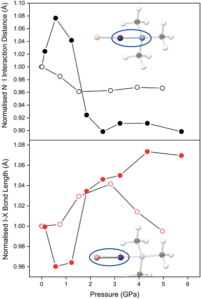
The refined TMA–ICl crystal structure at the lowest measured pressure (0.14 GPa) is in good agreement with that previously published.17 Compression of the crystal leads to a pronounced change in the distance between TMA and ICl, as it accommodates the increase in pressure. The variation in the N⋯I and I–Cl distances as a function of pressure is shown in Fig. 2. Following an initial increase in the N⋯I distance, it decreases by 10% at 6 GPa relative to ambient pressure. A corresponding increase of 7% is observed in the I–Cl distance. These changes can be ascribed to the relatively deformable electron cloud of the I atom in which a reversal of the δ+ and δ− regions is induced with pressure. The consequence of this electronic flexibility is that the full range of known I–Cl and I⋯N bonds (for I–Cl–N-containing crystal structures) can be reflected in this compound alone upon compression. By contrast in the TMA–I2 system the interaction distances remain relatively unchanged overall upon compression to 6 GPa (Fig. 2).
For TMA–ICl small increases in pressure are accommodated by changes within the N⋯I–Cl moiety. In crude terms, the energetic cost in deforming the N⋯I–Cl moiety away from its equilibrium value is less that than of increasing van der Waals repulsion between other atoms. At high pressure the overall compression of the TMA–ICl unit is accomplished by a decrease in the N⋯I distance, and an increase in the I–Cl distance. The changes in the bond distances suggest there is an increase in the covalent character of the N⋯I interaction at the expense of the covalent nature of the I–Cl bond. Similar behaviour has been reported for iodic acid.23 Once the N⋯I distance has attained a value commensurate with an N–I covalent bond, deformation is then achieved by a shearing of the N⋯I–Cl bond angle from 178.6(1)° to 172(2)° at 5.7 GPa. Conversely, in TMA–I2 the mechanism of compression does not manifest in the N⋯I–I fragment which remains unchanged across the pressure series.
The effect of pressure on TMA–I2 is more clearly seen via void reduction between neighbouring pairs of TMA–I2 units where the intermolecular I⋯I distance decreases substantially from 4.32(4) to 3.80(2) Å. At lower pressures this separation is too large to be considered a formal halogen bond, but at the highest pressure, it is possible that that this evolves into a type II halogen bond24 where the I–I⋯I and I⋯I–I angles are 100.5(6)° and 158.6(8)° at 4.96 GPa. However, we are unable to conclude whether this decrease is due to a type II interaction being favoured at higher pressures or because of the flexibility in the van der Waals radius of iodine.25,26
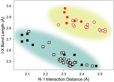
Analysis of structurally-comparable compounds in the Cambridge Structural Database (CSD) reveals particular flexibility in the case of TMA–ICl.¶ We find that on increasing pressure the I–Cl interaction progresses across all the known interaction distances in the reported literature. The scatter graph illustrating the variation of I–X (where X = I/Cl) and N⋯I distances is shown in Fig. 3. This reproduces the characteristic distribution shape for linear triatomic species and our pressure data also fall within this trend.27 In contrast a similar survey of literature results for I–I interactions shows a far reduced distribution of distances and our pressure study only reproduces a small subsection of this—see Fig. 3. It is interesting to see that such structurally-similar materials (TMA–I2 and TMA–ICl) show markedly different responses to pressure.
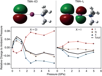
In order to rationalise the electronically-driven response in both compounds we calculated dipole moments and the highest occupied molecular orbital (HOMO) in Guassian03, shown in Fig. 4. Clear differences are immediately obvious between the two compounds. For TMA–ICl the HOMO is localised entirely on a pair of degenerate p-orbitals on the Cl atom rendering it sensitive to its chemical environment; weakening of the I–Cl bond is compensated for by favourable intermolecular interactions. This is not case for TMA–I2 where the HOMO takes the form of a π* orbital between the I atoms. The character of the respective HOMOs is unchanged with pressure in both compounds however, the redistribution of electron density leads to a marked change in dipole moment for TMA–ICl but not TMA–I2.
The greater electronegativity of the Cl atom—accumulating a build up of negative charge—means that it acts more readily as a hydrogen bond acceptor with neighbouring C–H groups than I. The H⋯Cl contacts in the ambient pressure TMA–ICl structure consistently rank among the shortest intermolecular distances across the pressure series. Given the charges and distances—whilst not formally a zwitterionic complex consisting of [(CH3)3NI]+ cations and Cl− anions—it would appear to be a better description than that of a typical halogen-bonded complex between (CH3)3N and ICl. To test this interpretation of the electronic structure we have performed DFT calculations using Gaussian03 with a default LanL2DXZ basis set; natural population analysis was used to identify the distribution of charge within the molecules. The change in charge distribution as a function of pressure is shown in Fig. 4. We find a clear indication that there is negligible charge transfer within TMA–I2, but substantially larger redistribution in TMA–ICl, associated with the decrease in the I–Cl bond length and increase in Cl charge density. As a consequence the computed dipole moment between N–X (X = terminal Cl/I) increases with pressure for TMA–ICl but is invariant for TMA–I2. Many functional devices exploit the electronic tunability of polar materials;28,29 the flexibility demonstrated in the TMA–ICl complex here highlights a tunable structural motif that may be well-suited for potential new materials.
In conclusion, we have shown that the complexes formed between TMA and I2 and ICl show markedly different responses to high pressure. Pressure-induced charge redistribution on the I atom in the TMA–ICl complex leads to substantial variation in the interatomic distances between the N, I, and Cl atoms, such that all previously-observed distance lengths are reproduced. The N⋯I interaction decreases to the extent that it approaches an N–I covalent bond, where the compound more closely resembles a zwitterion, i.e. [(CH3)3N–I]+ Cl−. The structurally similar TMA-I2 accommodates the effects of pressure through intermolecular compression rather than through any distortions in the formula unit. The changes in the ICl complex are possible due to the Cl electronic environment participating in interactions with adjacent hydrogen atoms, coupled with the soft, deformable electronic structure of the I atom. The greater ability of chlorine to accumulate negative charge was confirmed by calculations carried out on the experimental structures. The ability to tune or alter the charge distribution within the components of a halogen bond may have implications in the design of molecular materials with application in electronic devices.
Conflicts of interest
There authors declare no conflicts of interest.References
- F. Fernandez-Palacio, M. Poutanen, M. Saccone, A. Siiskonen, G. Terraneo, G. Resnati, O. Ikkala, P. Metrangolo and A. Priimagi, Chem. Mater., 2016, 28, 8314–8321 CrossRef CAS PubMed.
- L. J. McAllister, C. Präsang, J. P.-W. Wong, R. J. Thatcher, A. C. Whitwood, B. Donnio, P. O'Brien, P. B. Karadakov and D. W. Bruce, Chem. Commun., 2013, 49, 3946–3948 RSC.
- T. Apih, A. Gregorovič, V. Žagar and J. Seliger, Chem. Phys., 2019, 523, 12–17 CrossRef CAS.
- M. Eraković, D. Cinčić, K. Molčanov and V. A. Stilinović, Angew. Chem., Int. Ed., 2019, 58, 15702–15706 CrossRef PubMed.
- N. W. Alcock, Secondary Bonding to Nonmetallic Elements, Academic Press, 1972, vol. 15, pp. 1–58 Search PubMed.
- R. H. Jones and T. A. Hamor, J. Organomet. Chem., 1984, 262, 151–155 CrossRef CAS.
- A. K. Chauhan, A. Kumar, R. C. Srivastava, J. Beckmann, A. Duthie and R. J. Butcher, J. Organomet. Chem., 2004, 689, 345–351 CrossRef CAS.
- M. Boucher, D. Macikenas, T. Ren and J. D. Protasiewicz, J. Am. Chem. Soc., 1997, 119, 9366–9376 CrossRef CAS.
- A. J. Sindt, M. D. Smith, S. Berens, S. Vasenkov, C. R. Bowers and L. S. Shimizu, Chem. Commun., 2019, 55, 5619–5622 RSC.
- L. Brammer, A. Peuronen and T. M. Roseveare, Acta Crystallogr., Sect. C: Struct. Chem., 2023, 79, 204–216 CrossRef CAS PubMed.
- P. Metrangolo, L. Canil, A. Abate, G. Terraneo and G. Cavallo, Angew. Chem., Int. Ed., 2022, 61, e202114793 CrossRef CAS PubMed.
- V. Govindaraj, H. Ungati, S. R. Jakka, S. Bose and G. Mugesh, Chem. – Eur. J., 2019, 25, 11180–11192 CrossRef CAS PubMed.
- Y. Wang, X. R. Miao and W. L. Deng, Crystals, 2020, 10(11), 1057 CrossRef CAS.
- L. Zhao, K. Ma and Z. Yang, Int. J. Mol. Sci., 2015, 16, 8454–8489 CrossRef CAS PubMed.
- S. Fanetti, M. Citroni, K. Dziubek, M. M. Nobrega and R. Bini, J. Phys.: Condens. Matter, 2018, 30, 094001 CrossRef PubMed.
- A. Li, J. Wang, Y. Liu, S. Xu, N. Chu, Y. Geng, B. Li, B. Xu, H. Cui and W. Xu, Phys. Chem. Chem. Phys., 2018, 20, 30297–30303 RSC.
- W. G. Marshall, R. H. Jones, K. S. Knight, J. Clews, R. J. Darton, W. Miller, S. J. Coles and M. B. Pitak, CrystEngComm, 2017, 19, 5194–5201 RSC.
- W. G. Marshall, R. H. Jones and K. S. Knight, CrystEngComm, 2018, 20, 3246–3250 RSC.
- R. H. Jones, K. S. Knight, W. G. Marshall, J. Clews, R. J. Darton, D. Pyatt, S. J. Coles and P. N. Horton, CrystEngComm, 2014, 16, 237–243 RSC.
- R. H. Jones, C. L. Bull, K. S. Knight and W. G. Marshall, CrystEngComm, 2023, 25, 4146–4156 RSC.
- K. O. Stromme, Acta Chem. Scand., 1959, 13, 268–274 CrossRef CAS.
- M. J. Cliffe and A. L. Goodwin, J. Appl. Crystallogr., 2012, 45, 1321–1329 CrossRef CAS.
- B. B. Sharma, P. S. Ghosh, A. K. Mishra and H. K. Poswal, Vib. Spectrosc., 2021, 117, 103318 CrossRef CAS.
- S. Scheiner, Cryst. Growth Des., 2022, 22, 2692–2702 CrossRef CAS.
- S. C. Nyburg and C. H. Faerman, Acta Crystallogr. B, 1985, 41, 274–279 CrossRef.
- G. R. Desiraju and R. Parthasarathy, J. Am. Chem. Soc., 1989, 111, 8725–8726 CrossRef CAS.
- H. A. Bent, Chem. Rev., 1968, 68, 587–648 CrossRef CAS.
- A. Herlihy, T. A. Bird, C. J. Ridley, C. L. Bull, N. P. Funnell and M. S. Senn, Phys. Rev. B, 2022, 105, 094114 CrossRef CAS.
- T. Min, W. Choi, J. Seo, G. Han, K. Song, S. Ryu, H. Lee, J. Lee, K. Eom, C.-B. Eom, H. Y. Jeong, Y.-M. Kim, J. Lee and S. H. Oh, Sci. Adv., 2021, 7, eabe9053 CrossRef CAS PubMed.
Footnotes |
| † Electronic supplementary information (ESI) available. CCDC 2332025–2332038. For ESI and crystallographic data in CIF or other electronic format see DOI: https://doi.org/10.1039/d4cc00847b |
| ‡ Deceased. |
| § For clarity we designate all nitrogen iodine atom interactions as N⋯I regardless of where they lie on the continuum between halogen and covalently bonded regimes. |
| ¶ Ensuring the I atom is not part of a heterocycle and that the Cl and I are terminal atoms on the molecule. |
| This journal is © The Royal Society of Chemistry 2024 |


