
 Open Access Article
 This Open Access Article is licensed under a
 Creative Commons Attribution 3.0 Unported Licence
CO2-Based micro-respirometry for measuring bacterial load under aerobic and anaerobic conditions†
L.
McDonnell
 ,
D.
Yusufu
and
A.
Mills
*
,
D.
Yusufu
and
A.
Mills
*
School of Chemistry and Chemical Engineering, Queen's University Belfast, Stranmillis Road, Belfast, BT9 5AG, UK. E-mail: andrew.mills@qub.ac.uk
First published on 25th September 2024
Abstract
The bacterial load (BL), or total viable count, of aerobes can be measured using micro-respirometry, %O2-μR, in which the consumption of dissolved O2 is monitored with respect to incubation time, t. In %O2-μR the ‘bioreactor’ often comprises a canonical plastic tube with a small %O2 sensor; it is simple, fast and accurate and used in automated, commercial instruments for measuring BL. Here we show that it is also possible to measure BL using a new form of micro-respirometry, %CO2-μR, in which the production of CO2 in the growth medium is monitored. In %CO2-μR, the ‘bioreactor’ is the same as that used in %O2-μR, but with a small 3D printed, colour-based %CO2 indicator set in its base and its apparent absorbance, A′, is measured at any t, as it is related to the %CO2 dissolved in the inoculated growth medium. Under aerobic conditions, different inoculations of the facultative anaerobe, E. coli, of different concentrations (101–108 colony forming units (CFU) per mL) are used to generate a series of A′ vs. t profiles, and a straight-line calibration curve. Statistical comparative analysis of the results generated in the above %CO2-μR study, to those generated for the same system but using a commercial %O2-μR system, is used to demonstrate method equivalence. A study of the same system, under anaerobic conditions, using %CO2-μR, shows that %CO2-μR is suitable for measuring the BL of anaerobes. The potential of %CO2-μR for measuring the bacterial load of CO2-generating aerobes and anaerobes is discussed briefly.
1. Introduction
The measurement of the bacterial load (BL), or total viable count, of aerobes, units: colony forming units (CFU) per mL, is an important part of microbiology practice and is used extensively in food safety, clinical analysis and environmental monitoring.1 The usual method for measuring BL is the plate counting method, PCM,2,3 but it is time consuming, laborious (as it involves multiple dilutions and counting), expensive (as it consumes a lot of plasticware), usually has a subjective element (as it involves colony counting) and slow, taking up to 72 h.4,5 The use of PCM for measuring the BL of aerobes is relatively straightforward, but less so for anaerobes, as it requires a not inexpensive O2-free system for handling and incubating the plates, such as an anaerobic chamber and/or an anaerobic jar.6–9Given the importance of making BL measurements in research, the food industry, the environment, and healthcare, there is an increasing need for a rapid, inexpensive method that can be automated to allow the high throughput of samples. In the case of aerobe BL measurements, one very popular alternative to PCM is O2 micro-respirometry, which involves monitoring the consumption of O2 due to bacterial growth and respiration, and which herein is referred to as %O2-μR.1,10–12 Note, although the rate of O2 consumption, as measured using %O2-μR, is most often used as a measure of the rate of microbial metabolism, the rate of generation of a product of metabolism, such as CO2, can also be used for this purpose.
In %O2-μR, the decrease in the concentration of O2 (units: %O2, where 100% = a partial O2 pressure of 1 atm), due to the respiration of a dispersion of an aerobe in an initially air-saturated growth medium, is monitored with respect to incubation time, t, and a value for the threshold time, TT, taken to reach a set %O2 value (the threshold level) is measured. For each bacterial species under study, the system is first calibrated by measuring the value of TT with respect to initial bacterial load, for a series of different loads, and the results used to produce a calibration plot of log(CFU per mL) vs. TT, which is usually a straight line. This calibration line is used subsequently to calculate the log(CFU mL−1) value, i.e., BL, in any subsequent sample, from its measured value for TT.1,11,12
In %O2-μR, an O2-sensitive luminescent dye is usually employed to monitor the %O2 in the growth medium via its luminescence lifetime, τ, and the Stern–Volmer equation,
| τo/τ = 1 + Ksv%O2 | (1) |
Clearly, %O2-μR cannot be used to evaluate anaerobe BL levels. However, given most aerobes, and many anaerobes, generate CO2 as they respire,13 it should be possible to measure the BL levels of both these types of microbial species using a micro-respirometry method (%CO2-μR) based on the increase in the dissolved CO2 concentration (units: %CO2) in the growth medium with respect to t. %CO2-μR requires a %CO2 indicator that works in the growth medium and, although many colour and luminescence-based %CO2 indicators exist, most are based on ink films that are not stable in a typical growth medium which contains salts, either due to dye leaching or ion-exchange, which usually leads to the permanent protonation of the dye.14 In addition, %CO2-μR would require the absorbance of the indicator to be measured using a UV/Vis spectrophotometer, which would contribute significantly to its cost.
The above two apparent barriers to the widespread use of %CO2-μR for measuring the BL of aerobes and anaerobes have been addressed separately in recent work carried out by this group. Thus, this group has reported a method of encapsulating CO2-sensitive pigment particles in an extrudable polymer film, like low density polyethylene, LDPE, which can then be 3D printed as a thin plastic film %CO2 indicator that can measure the %CO2 in fresh and seawater over long a long time periods (>3 months).15,16 The LDPE makes these %CO2 indicators very stable, even in very salty aqueous medium, since it acts as a gas-permeable, ion-impermeable, membrane that covers the pigment particles that are CO2-sensitive, in much the same way as the polymer membrane, often polypropylene, protects the integral pH electrode in the Severinghaus CO2 electrode.17 This group has also demonstrated that expensive UV/Vis spectrophotometry, for measuring the absorbance, A, of a %CO2 indicator, can be readily replaced by inexpensive digital photography, coupled with digital colour analysis, DCA, which provides a measure of the indicator's apparent absorbance, A′, which is related directly to A.14,18 In this paper a 3D printed %CO2 indicator, analysed using digital photography + DCA, is used to create, for the first time, a simple %CO2-μR method for measuring BL of both aerobes and anaerobes.
2. Experimental
2.1. Materials
All chemicals and solvents were purchased from Merck (Gillingham, UK), unless stated otherwise. Double-distilled, deionized water was used to prepare all aqueous solutions. All gases, including the different %CO2/N2 gas mixtures used to calibrate the XB/LDPE indicator, were from BOC (Surrey, UK). KWIK STIK stock cultures of Escherichia coli (E. coli, ATCC 8739), a facultative anaerobe, were from Microbiologics (St Cloud, Minnesota, USA). The Falcon™ disposable sample tubes, with proprietary O2-sensitive PtBP indicator, were purchased from Oculer Ltd (Tipperary, Ireland). Preparation details of the liquid growth medium used in this work are given in S1 of the ESI† and those for making the stock dispersions of E. coli are given in S2 of the ESI.†2.2. The 3D printed plastic film CO2-sensitive indicator
The 3D printed plastic film CO2-sensitive indicator comprised CO2-sensitive pigment particles encapsulated in LDPE. The pigment particles were nanoparticles of silica coated with a pH-sensitive dye, xylenol blue, XB, and a base, tetrabutyl ammonium hydroxide. The preparation of the CO2-sensitive XB/SiO2 pigment and its use to produce a masterbatch of XB/LDPE pellets, which were then used to produce a 3D printable filament, is described elsewhere.19 In this work, this filament was printed to produce the %CO2 indicator on Tyvek™, 50 μm thick, 5 mm square, illustrated in Fig. 1.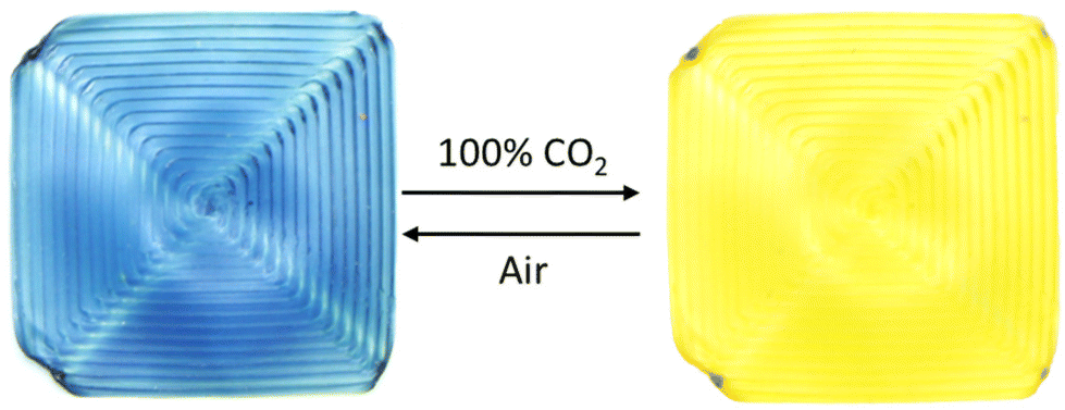 | ||
| Fig. 1 3D printed XB/LDPE indicator in air and CO2. | ||
The experimental conditions used to produce the filament and 3D printed CO2-sensitive indicator were the same as those reported previously for a 3D printed O2-sensitive indicator.20 As shown in Fig. 1, the 3D-printed XB/LDPE (CO2-sensitive) indicator was blue in air, and yellow in the presence of 100% CO2.
2.3. The Falcon™ tube ‘bioreactor’ and apparent absorbance, A′, and lifetime, τ, measurements
A schematic illustration and photographs of the typical %CO2-μR ‘bioreactor’ used in this work are illustrated in S3, Fig. S1 of ESI† and comprised a 15 mL Falcon™ tube, with a proprietary, luminescence-based, %O2 indicator (Oculer Ltd, Tipperary, Ireland) set in its base, to which was added a 3D printed XB/LDPE %CO2 indicator, printed on Tyvek™, secured in place using surgical tape, see Fig. S1 in the ESI.† In a typical experiment, the Falcon™ tube ‘bioreactor’ was filled with 9 mL of the relevant growth medium and 1 mL of the E. coli inoculum under test, mixed, and then placed in an incubation cabinet set at 30 °C (Thermo Scientific™ Heratherm™ Compact Microbiological Incubator, Thermo Fisher Scientific, Massachusetts, USA). Photographic images of the XB/LDPE %CO2 indicator, and the lifetime, τ, of the luminescent %O2 indicator were then measured simultaneously with respect to the incubation time, t. Each photographic image was analysed using DCA, to provide a value for the apparent absorbance, A′, of the %CO2 indicator; details of the data processing involved are given elsewhere.18 All luminescence lifetime, τ, measurements of the luminescent Oculer %O2 indicator were made with a Pyroscience FireSting-O2 fibre-optic oxygen meter (Aachen, Germany).21 This meter monitors the phase shift, Δϕ, of the luminescence emitted by the sensor compared to that of the modulated excitation light, ν = 4 kHz, which is readily transformed into a value for τ, given tan(Δϕ) = 2πντ.1In this work, all digital photography was carried out using a Canon EOS 700D digital camera (Canon Inc., London, UK) to record images of the 3D printed %CO2 indicator through the glass front window of the incubator, lit using a D65 daylight lamp (HiraLite 14 W full spectrum Daylight lamp, Amazon, UK). Before any photographic images were taken, the custom white balance feature was activated on the camera using a white card, so that the camera locked into the colour temperature of the D65 daylight lamp from the light reflected from the card.
2.4. Statistical analysis
All straight-line plots of data were analysed using the method of least squares which generated values for the gradient and its error, m ± Δm, intercept and its error, c ± Δc, and Pearson correlation coefficient, r. In this work all reported error values are for the 95% confidence interval (CI), and calculated from the associated standard deviation value, σ, using CI = 1.96 × σ.When comparing the different abilities of %O2-μR for measuring BL (an established reference–technique like PCM) and that of %CO2-μR (a new method) an Altman–Bland (A–B) analysis was used.22 Thus, in this work, the difference, d, was plotted against the mean, log(CFU)Av, where,
| d = log(CFU mL−1)%O2-μR − log(CFU mL−1)%CO2-μR | (2) |
| log(CFU)Av = (log(CFU mL−1)%O2-μR + log(CFU mL−1)%CO2-μR)/2 | (3) |
![[d with combining macron]](https://www.rsc.org/images/entities/i_char_0064_0304.gif) = 0), (ii) mean difference, , and (iii) the limits of agreement ( ± CI). It is also usual to have a shaded area that covers the confidence limits of , which are defined as lying between + (σ2/n)0.5 and − (σ2/n)0.5, where n = number of data points.22 In such a plot, the two methods are usually considered equivalent if, (i) the shaded grey area encompasses the line of equality, (ii) all the data points lie within the limits of agreement and (iii) the data points appear randomly distributed.22
= 0), (ii) mean difference, , and (iii) the limits of agreement ( ± CI). It is also usual to have a shaded area that covers the confidence limits of , which are defined as lying between + (σ2/n)0.5 and − (σ2/n)0.5, where n = number of data points.22 In such a plot, the two methods are usually considered equivalent if, (i) the shaded grey area encompasses the line of equality, (ii) all the data points lie within the limits of agreement and (iii) the data points appear randomly distributed.22
All PCM and μR BL assays were carried out in triplicate and the average value taken, and in all measurements the CI was ≤±0.1 log(CFU mL−1).
3. Results and discussion
3.1. Initial study of the response characteristics of the XB/LDPE indicator
For colourimetric %CO2 indicators, such as the 3D printed XB/LDPE indicator used here, it can be shown that the measured value of A′ is related to the %CO2 in the medium surrounding the indicator via,| R = (A′0 − A′)/(A′ − A′∞) = α%CO2 | (4) |
The sensitivity of the XB/LDPE indicator towards %CO2 was measured by placing the indicator in 9 mL of nutrient broth (NB, see S1 in the ESI†) at 30 °C, sparging the solution with different known %CO2/N2 blends, and photographing the indicator each time as illustrated in Fig. 2(a). Each image, associated with a known value of %CO2, was analysed using DCA to obtain the corresponding value of A′, which in turn was used to calculate a value for R, using eqn (4).
 | ||
| Fig. 2 (a) Photographic images of the XB/LDPE indicator in NB at 30 °C, saturated with different known levels of %CO2; (b) plot of R vs. %CO2, where R was calculated using eqn (4) and the DCA calculated values of A′ derived from the photos in (a). | ||
The subsequent straight line plot R vs. %CO2, arising from this analysis of the photos in Fig. 2(a), is shown in Fig. 2(b), with m, i.e., α, = 0.73 ± 0.04%−1, which indicates a halfway colour transition value (from blue to yellow) (= 1/α) of 1.38 ± 0.08%CO2.
In other work, the 90% response (0 to 5%), and recovery (5 to 0%), times of the 3D-printed XB/LDPE indicator were calculated by measuring A′ vs. time, t, as the atmosphere surrounding the indicator was changed from air to 5%CO2 and back again in a continuous cycle. The results of this work are shown in S4, Fig. S2 in the ESI,† and values for the 90% response and recovery times in the variation in A′ of 8 and 14 min, respectively, were calculated. Reassuringly, as we shall see, in a typical μR experiment the period over which the dissolved %CO2 starts to change rapidly is ca. 60 min, and so considerably longer that the 90% response time of the %CO2 indicator.
An important aspect of this work is the method of production of the %CO2 indicator, i.e., 3D printing, as it is inexpensive, quick, easy to use, and scalable. In order to test how reproducible the 3D printing process was in the production of the XB/LDPE %CO2 indicators, twenty were printed and the values of A′0, A′∞, and α, exhibited by each indicator, were measured in NB at 30 °C.
The results of this work are illustrated in Fig. 3, and show that the measured values of A′0, A′∞, and α for the twenty 3D printed XB/LDPE %CO2 indicators are very consistent, with an average sensitivity (α) of 0.74 ± 0.02%−1, which equates to a % variation of only ca. 2.3%. This % variation in sensitivity value is only slightly higher than that that (1.7%) reported by others for an array of %O2 indicators produced using a commercial ink made for %O2-μR.23
 | ||
| Fig. 3 Plots of measured values of A′∞ (closed black circles), A′0 (open black circles), and α (red circles) for 20 different 3D printed XB %CO2 indicators. The results of this work reveal a high degree of consistency with A′0 = 0.98 ± 0.02, A′∞ = 0.11 ± 0.01, and α = 0.74 ± 0.02%−1, i.e., a variation in α of ca. 2.3%. | ||
3.2. %CO2-μR for measuring BL under aerobic conditions
Under aerobic conditions, in the growth medium used in this work, E. coli utilises the following reaction to generate the necessary energy for growth, and in so doing consumes O2 and generates CO2.13| Glucose (C6H12O6) + 6O2 → 6CO2 + 6H2O | (5) |
As noted earlier, the BL of an aerobe is routinely measured using %O2-μR, by monitoring the consumption of O2, but given respiration reaction (5) it follows that it should also be possible to measure the BL for a sample by monitoring the generation of CO2, i.e. using %CO2-μR, instead of %O2-μR. Thus, in a typical %CO2-μR experiment, 1 mL of 104 CFU mL−1 of the E. coli bacteria, made by diluting the stock dispersion of the E. coli of known concentration (see S2 in the ESI†), was used to inoculate 9 mL of NB in a 15 mL Falcon™ tube. The inoculated solution was inverted to mix the two solutions, and then incubated at 30 °C. Digital photography was then used to measure the variation in A′ of the %CO2 indicator, and, at the same time, the Pyroscience O2 meter was used to measure the variation in the lifetime, τ, of the Oculer %O2 indicator which was also present, with respect to incubation time, t. Fig. 4(a) shows a typical collection of photographic images, from which the values of A′ vs. t, illustrated in Fig. 4(b), were calculated using DCA. The latter values were then used to calculate the %CO2 (using eqn (4) and α = 0.74%−1) vs. t data points illustrated in Fig. 4(c). Similarly, the simultaneously measured values of τ vs. t in Fig. 4(b), combined with eqn (1) and Ksv = 0.09%O2−1, allowed the %O2vs. t data points in Fig. 4(c) to be calculated.
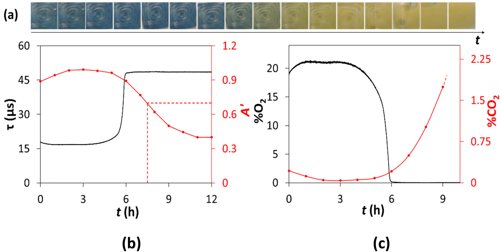 | ||
| Fig. 4 (a) Recorded digital photographs of a XB/LDPE %CO2 indicator in NB inoculated with 104 CFU mL−1E. coli under aerobic conditions; (b) plot of the measured τ (for %O2 indicator), and calculated A′ (for %CO2 indicator derived from photos in (a)) values, vs. incubation time, t. The vertical red broken line identifies the threshold time, TT, (7.5 h) for this run, when A′ = 0.7. (c) Plot of %O2 and %CO2vs. t, calculated using the data in (b), with Ksv = 0.09%O2−1 and α = 0.74%−1, respectively. | ||
A notable feature of the results in Fig. 4(b) is the initial changes in the apparent absorbance, A′, and luminescence lifetime, τ, values in the first 1.5 h of the incubation period. This feature is due to the inoculated Falcon™ tube bioreactor, with the indicators set in its base, see Fig. S1 in ESI,† warming up when first placed inside the incubator. Another, and initially puzzling, feature of the %O2 and %CO2vs. t profiles illustrated in Fig. 4(b), is the apparent faster O2 consumption kinetics compared to that of CO2 generation, so that, by the time all 21% of the dissolved O2 has been consumed (ca. 5.8 h), only 0.2%CO2 has been generated. Interestingly, similar results have been reported by Arain et al. in a μR study in which the variation of %O2 and %CO2 (measured indirectly using a pH indicator) were measured with respect to t.24 It appears likely that this delay is due to the combination of two kinetic features namely, (i) the lag between the consumption of O2 compared with that CO2 production inside the cell, because mechanistically the former is a precursor to the latter via a complex series of reactions, and (ii) the faster kinetics of O2 diffusion into the cell compared to those for CO2 diffusion out of the cell, where it is detected.
The reproducibility of the %CO2-μR method was tested by repeating the same experiment as above ten times and using the results to generate the ten A′ vs. t plots shown in S5, Fig. S3 in the ESI.† These results were used to calculate an average value of TT = 7.43 ± 0.18 h, i.e., a % variance of ±2.4%, which indicates that the %CO2-μR methodology for one inoculum at least is very reproducible. To test the %CO2-μR method more fully, the same set up as above was used to generate a series of A′ vs. t profiles for different inoculum concentrations of E. coli under aerobic conditions, the results of which are illustrated in Fig. 5(a), with the original photographs, from which the values of A′ were calculated, shown in S6, Fig. S4 in the ESI.† These results were then used to construct the usual straight line calibration plot of log(CFU mL−1), vs. TT, which is illustrated in Fig. 6(b) and, as noted before for %O2-μR, can then be used to determine the BL load in any subsequent samples.
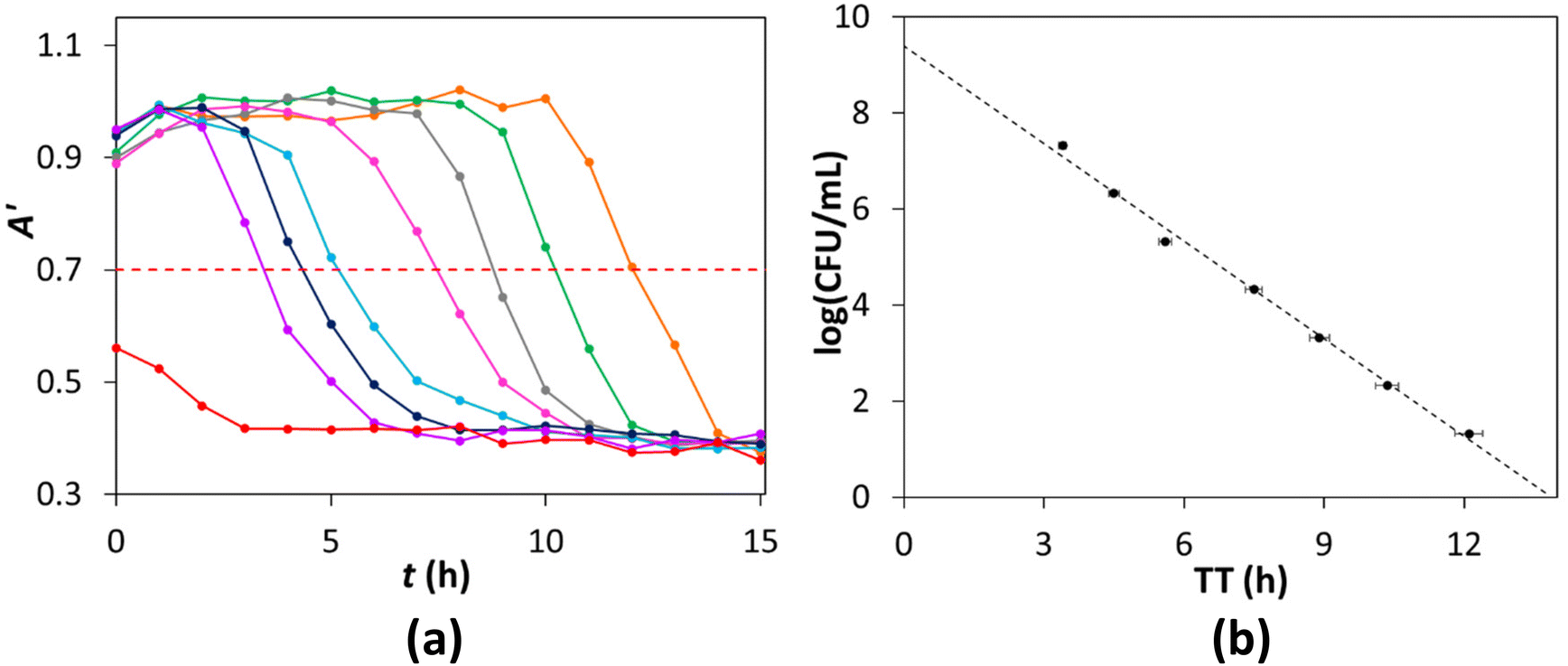 | ||
| Fig. 5 (a) A′ vs. incubation time, t, profiles, calculated using DCA from the photos in Fig. S4 in the ESI,† for a series of 1 mL, 10-fold dilutions of the E. coli stock culture, covering 108 to 101 CFU mL−1, in units of ten from left to right, used to inoculate 9 mL of NB under aerobic conditions. The red dashed line highlights the value of TT, for each inoculum, for when A′ = 0.7; (b) initial inoculum BL, log(CFU mL−1), vs. TT, derived from the data in (a). A line of best fit analysis of the data (dashed line) reveals m ± Δm = −0.68 ± 0.02 log(CFU mL−1) h−1 and c ± Δc = 9.4 ± 0.2 log(CFU mL−1). | ||
 | ||
| Fig. 6 BL values of 14 different E. coli samples were measured using %CO2-μR and %O2-μR systems and the results plotted in (a) as log(CFU mL−1)%CO2-μRvs. log(CFU mL−1)%O2-μR and (b) as d vs. log(CFU)Av, as defined by eqn (2) and (3). and the limits of agreement are represented by the broken red and blue lines, respectively. The grey band depicts the 's confidence limits and the broken black line, where d = 0.22,25 | ||
The above results suggest that the XB/LDPE %CO2 indicator can be used in μR to measure BL under aerobic conditions and is a first reported example of %CO2-μR in which the %CO2 was measured directly using a %CO2 sensor.
3.3. Comparison of %CO2-μR and %O2-μR for measuring BL under aerobic conditions
When introducing any new method for measuring a quantity, such as BL in this work, it is necessary to run the same samples through the new method and an established, reference, method and then to compare the results. In this work %O2-μR was chosen as the reference method for measuring BL, and was run using a commercial instrument and its plastic tube bioreactors (Oculer Rapid 930) designed for this purpose.11 Thus, 14 dispersions of E. coli of different BL, covering 107 to 101 CFU mL−1, were prepared and in each case the BL was measured using both %CO2-μR and %O2-μR. In this work the experimental set up and protocol were the same as that used in Fig. 5, with the exception that the Falcon™ tube had either a %CO2 indicator or a commercial (Oculer) %O2 indicator set in its base.The simplest and most common method employed to compare the results, generated by two methods that measure the same quantity, is to plot them against each other, since ideally, a straight line should be generated with the gradient, m = 1, the intercept, c = 0 and the square of the correlation coefficient, r2 = 1.22 A rough guide to the degree of the equivalence of the two methods is provided by how far the actual values of m, c and r, deviate from the ideal, namely, m = 1, c = 0 and r = 1, and whether these ideal values of m and c fall within the limits of agreement described by m ± Δm and c ± Δc, respectively.
The plot of log(CFU mL−1)%CO2-μRvs. log(CFU mL−1)%O2-μR, for the 14 samples is illustrated in Fig. 6(a) and reveals values for m, c and r, of 0.993 ± 0.06, −0.0013 ± 0.30 and 0.9941, respectively. These results suggest that %CO2-μR and %O2-μR, can be considered equivalent, since the ideal values of 1 and 0 lie with the limits of agreement (e.g., 0.993 + 0.06 to 0.993 − 0.06 for m) for m and c, respectively.
The above straight line plot analysis of the data is not sufficiently rigorous to be sure the two methods are equivalent and so it is usual to also construct an A–B plot of the data. The A–B plot of the data in Fig. 6(a), illustrated in Fig. 6(b), shows the data points are randomly distributed about (= 0.03) and within the limits of agreement (0.03 ± 0.46). A Shapiro–Wilk normality test on the differences showed the data were normally distributed (P = 0.548). In addition, in Fig. 6(b), it can be seen that the grey shaded area, defined by the confidence intervals of , (0.03 ± 0.06), encapsulates the black broken line of equality (d = 0), which indicates that there is little, or no, significant bias between the two methods.25 Thus, the A–B plot illustrated in Fig. 6(b) indicates that the new %CO2-μR method is equivalent to the reference %O2-μR method for measuring BL.
3.4. %CO2-μR for measuring BL of under anaerobic conditions
Given E. coli is a Gram-negative, facultative anaerobe,26 it follows that under anaerobic conditions it can generate the energy needed for growth via fermentation. In the case of E. coli the major soluble fermentation products are acetate, ethanol, lactate, formate, and some succinate, and the major gaseous products are H2 and CO2.27 However, E. coli is just one of many facultative and non-facultative anaerobes that generate CO2 from glucose via its fermentation13 and it should be possible to use %CO2-μR to measure the BL of such anaerobes by monitoring the generation of CO2.The latter idea was tested using E. coli and the same growth NB as before plus sodium sulfite, Na2SO3, as the latter is very effective in removing dissolved O2 from aqueous solution.28 Thus, in a typical experiment, a 1 mL inoculum of 104 CFU mL−1E. coli was added to 9 mL of the NB, containing 50 mg of Na2SO3, in a Falcon™ tube with both a XB/LDPE %CO2 and Oculer %O2 indicator set in its base, see Fig. S1 in the ESI.† The inoculated Falcon™ tube was then quickly stoppered, incubated at 30 °C and the apparent absorbance, A′, of the %CO2 indicator, and τ of the %O2 indicator monitored with incubation time, t.
The results of this work in the form of plots of τ (for the %O2 indicator) and A′ (derived from photographs of the %CO2 indicator using DCA) vs. t are shown in Fig. 7 and show, as expected, that the concentration of dissolved O2, %O2, remained approximately 0 throughout the 22 h run (since τ ≈ τo), whereas the concentration of %CO2 increased (and so A′ decreased) with increasing t, due to the fermentation-driven growth of the E. coli. A comparison of the two A′ vs. t profiles due to the generation of CO2, illustrated in Fig. 4(b) and 7, under aerobic and anaerobic conditions, respectively, shows that the TT values, for an otherwise identical μR experiment, are 7.5 and 12 h, respectively. This feature is consistent with the well-known observation that, under the same conditions, E. coli's growth kinetics due to respiration in air are faster than that associated with fermentation in the absence of air.
 | ||
| Fig. 7 Typical lifetime, τ, and apparent absorbance, A′, vs. t, profile for a μR experiment, with an inoculum of 104 CFU mL−1E. coli, recorded under anaerobic conditions. The red dashed lines identify the TT value, 12 h, when A′ = 0.7. | ||
The results illustrated in Fig. 7 suggest that it should be possible to use %CO2-μR to measure the BL of CO2-generating facultative and non-facultative anaerobes. To test this proposition, the same experimental conditions as used above were employed to generate a series of A′ vs. t profiles for different concentrations of E. coli under anaerobic conditions and the results are illustrated in Fig. 8(a). Note, the original photographs, from which the values of A′ were calculated, are given in S6, Fig. S5 in the ESI.†
 | ||
| Fig. 8 (a) A′ vs. t profiles, calculated using DCA and the photos illustrated in Fig. S5 in the ESI,† for a series of 1 mL, 10-fold dilutions of the E. coli stock culture, from 108–101 CFU mL−1, in units of ten from left to right, used to inoculate 9 mL of NB under anaerobic conditions. The red dashed line identifies the TT value, for each inoculum, for when A′ = 0.7. (b) Log(CFU mL−1), vs. TT, based on the data in (a). A line of best fit analysis of the data (dashed line) reveals m ± Δm = −0.52 ± 0.01 log(CFU mL−1) h−1 and 10.4 ± 0.2 log(CFU mL−1), respectively. | ||
The above results, based on E. coli dispersions under anaerobic conditions, show that the XB/LDPE %CO2 indicator can be used in μR for assessing the BL of CO2-generating anaerobes as it is able to generate a good straight calibration line plot of log(CFU mL−1) vs. TT, as illustrated in Fig. 8(b). As with aerobic μR for measuring BL, such a calibration plot can then be used to determine a value for the log(CFU mL−1) in any subsequent sample containing the anaerobe under test, from its measured TT value recorded under the same anaerobic conditions.
4. Conclusions
%CO2-μR can be used to measure the BL of E. coli under aerobic conditions and, although, under the same conditions, the evolution of CO2 is slower that the consumption of O2, both %CO2-μR and %O2-μR are much faster than the traditional plate counting method for measuring BL. The %CO2 indicator is 3D printed, inexpensive, and its production can be readily scaled up. Statistical analysis of the BL results generated for 14 samples of different E. coli concentration using %CO2-μR, when compared to those generated for the same samples using a commercial %O2-μR system as a reference method, shows that the two methods are equivalent. %CO2-μR can also be used to measure the BL of E. coli under anaerobic conditions and so should be able to measure the BL of any CO2-generating aerobe or anaerobe. There are numerous undesirable features associated with the traditional plate counting method for measuring BL, including its labour-intensive nature and unsuitability for automation. When it comes to measuring the BL of anaerobes, PCM has the additional problems of working in an anaerobic environment, the provision of which is not inexpensive. %O2-μR is an established, excellent, rapid, easy to use method for measuring the BL of aerobes which has been automated and commercialised. This work shows that %CO2-μR has the potential to at least compliment if not replace %O2-μR, as it can be used to measure the BL of both aerobes and anaerobes, and so is likely to have a significant impact on current practice in microbiological analysis laboratories.Author contributions
Lauren McDonnell Validation, formal analysis, investigation, writing – original draft. Dilidaer Yusufu Conceptualization, methodology, validation, visualization. Andrew Mills Conceptualization, writing – review & editing, supervision, project administration, funding acquisition.Data availability
All data is provided in full in the results section of this paper and ESI† accompanying this paper.Conflicts of interest
The authors declare that they have no known competing financial interests or personal relationships that could have appeared to influence the work reported in this paper.Acknowledgements
This work was funded by the EPSRC (EP/T007575/1).References
- D. B. Papkovsky and J. P. Kerry, Oxygen sensor-based respirometry and the landscape of microbial testing methods as applicable to food and beverage matrices, Sensors, 2023, 23, 4519 CrossRef CAS PubMed.
- ISO 4833-1, ISO 4833-1:2013, Microbiology of the food chain-horizontal method for the enumeration of microorganisms-part 1: colony count at 30 °C by the pour plate technique, International Organization for Standardization, Geneva, 2013.
- Y. Tanaka, H. Takahashi, A. Imai, T. Asao, S. Kozaki, S. Igimi and B. Kimura, Reconsideration of flexibility in verifying rapid alternative food microbiological methods, Food Control, 2010, 21, 1075–1079 CrossRef.
- V. Jasson, L. Jacxsens, P. Luning, A. Rajkovic and M. Uyttendaele, Alternative microbial methods: an overview and selection criteria, Food Microbiol., 2010, 27, 710–730 CrossRef PubMed.
- R. Hazan, Y.-A. Que, D. Maura and L. G. Rahme, A method for high throughput determination of viable bacteria cell counts in 96-well plates, BMC Microbiol., 2012, 12, 259 CrossRef PubMed.
- J. McIntosh and P. Fildes, A new apparatus for the isolation and cultivation of anaerobic microorganisms, Lancet, 1916, 1, 768–770 CrossRef.
- J. A. Smith and J. H. Ngui-Yen, Anaerobic plate method for assaying antimicrobial agents in serum, Antimicrob. Agents Chemother., 1981, 20, 678–680 CrossRef CAS PubMed.
- L. M. Mauerhofer, P. Pappenreiter, C. Paulik, A. H. Seifert, S. Bernacchi and S. K. R. Rittmann, Methods for quantification of growth and productivity in anaerobic microbiology and biotechnology, Folia Microbiol., 2019, 64, 321–360 CrossRef CAS PubMed.
- R. G. Bell, N. Penney and S. M. Moorhead, Comparison of aerobic and anaerobic methods for the microbiological monitoring of chilled packaged meat during storage, Lett. Appl. Microbiol., 1997, 24, 265–268 CrossRef CAS PubMed.
- A. Hempel, N. Borchert, H. Walsh, K. Roy Choudhury, J. P. Kerry and D. B. Papkovsky, Analysis of total aerobic viable counts in raw fish by high-throughput optical oxygen respirometry, J. Food Prot., 2011, 74, 776–782 CrossRef CAS PubMed.
- R. Fernandes, C. Carey, J. Hynes and D. Papkovsky, GreenLight Model 960, J. AOAC Int., 2013, 96, 369–385 CrossRef CAS PubMed.
- The Oculer 930 Series, https://oculer.com/technology_tech_Soft.html, (accessed July 2024).
- G. Gottschalk, Bacterial Metabolism, Springer-Verlag, New York, USA, 2nd edn, 1986 Search PubMed.
- A. Mills, L. McDonnell and D. Yusufu, Colorimetric CO2 Indicators, Acc. Mater. Res., 2023, 4, 570–579 CrossRef CAS PubMed.
- A. Mills and D. Yusufu, Extruded colour-based plastic film for the measurement of dissolved CO2, Sens. Actuators, B, 2016, 237, 1076–1084 CrossRef CAS.
- L. McDonnell, D. Yusufu, C. O'Rourke and A. Mills, CO2 measurement in aquaria using a plastic film colourimetric indicator, Sens. Actuators, B, 2024, 412, 135859 CrossRef CAS.
- J. W. Severinghaus and A. F. Bradley, Electrodes for blood pO2 and pCO2 determination, J. Appl. Physiol., 1958, 13, 515–520 CrossRef CAS PubMed.
- D. Yusufu and A. Mills, Spectrophotometric and digital colour colourimetric (DCC) analysis of colour-based indicators, Sens. Actuators, B, 2018, 273, 1187–1194 CrossRef CAS.
- D. Yusufu, E. Magee, B. Gilmore and A. Mills, Non-invasive, 3D printed, colourimetric, early wound-infection indicator, Chem. Commun., 2022, 58, 439–442 RSC.
- D. Yusufu, R. Han and A. Mills, 3D printed O2 indicators, Analyst, 2020, 145, 4124–4129 RSC.
- M. Watson, D. Yusufu and A. Mills, Simple, reusable, solid-state system for measuring total (aerobic) viable count, TVC, using the micro-respirometry method (μRM), Sens. Actuators, B, 2024, 406, 135435 CrossRef CAS.
- D. G. Altman and J. M. Bland, Measurement in medicine: the analysis of method comparison studies, J. R. Stat. Soc., D, 1983, 32, 307–317 Search PubMed.
- E. Santovito, S. Elisseeva, A. Bukulin, J. P. Kerry and D. B. Papkovsky, Facile biosensor-based system for on-site quantification of total viable counts in food and environmental swabs, Biosens. Bioelectron., 2021, 176, 112938 CrossRef CAS PubMed.
- S. Arain, G. T. John, C. Krause, J. Gerlach, O. S. Wolfbeis and I. Klimant, Characterization of microtiterplates with integrated optical sensors for oxygen and pH, and their applications to enzyme activity screening, respirometry, and toxicological assays, Sens. Actuators, B, 2006, 113, 639–648 CrossRef CAS.
- D. Giavarina, Understanding Bland Altman analysis, Biochem. Med., 2015, 25, 141–151 CrossRef PubMed.
- N. Allocati, M. Masulli, M. F. Alexeyev and C. Di Ilio, Escherichia coli in Europe: an overview, Int. J. Environ. Res. Public Health, 2013, 10, 6235–6254 CrossRef PubMed.
- D. P. Clark, The fermentation pathways of Escherichia coli, FEMS Microbiol. Rev., 1989, 63, 223–234 CrossRef CAS PubMed.
- K. H. Rashid and A. A. Khadom, Sodium sulfite as an oxygen scavenger for the corrosion control of mild steel in petroleum refinery wastewater: optimization, mathematical modeling, surface morphology and reaction kinetics studies, React. Kinet., Mech. Catal., 2020, 129, 1027–1046 CrossRef CAS.
Footnote |
| † Electronic supplementary information (ESI) available. See DOI: https://doi.org/10.1039/d4an01016g |
| This journal is © The Royal Society of Chemistry 2024 |