
 Open Access Article
 This Open Access Article is licensed under a
 Creative Commons Attribution 3.0 Unported Licence
Lithiation/delithiation of silicon heavily doped with boron synthesized using the Czochralski process†
Masahiro
Shimizu
 *a,
Kohei
Kimoto
a,
Ayaka
Kikuchi
b,
Toshinori
Taishi
c and
Susumu
Arai
a
*a,
Kohei
Kimoto
a,
Ayaka
Kikuchi
b,
Toshinori
Taishi
c and
Susumu
Arai
a
aDepartment of Materials Chemistry, Faculty of Engineering, Shinshu University, 4-17-1 Wakasato, Nagano, 380-8553, Japan. E-mail: shimizu@shinshu-u.ac.jp; Fax: +81-26-269-5627; Tel: +81-26-269-5627
bTechnical Division, Faculty of Engineering, Shinshu University, 4-17-1 Wakasato, Nagano, 380-8553, Japan
cDepartment of Electrical and Computer Engineering, Shinshu University, 4-17-1 Wakasato, Nagano, 380-8553, Japan
First published on 20th April 2023
Abstract
The effects of B doping and its impurity concentration (1600, 4700, and 12![[thin space (1/6-em)]](https://www.rsc.org/images/entities/char_2009.gif) 400 ppm) on the electrochemical lithiation/delithiation of Si, which has the potential to replace graphite currently used as a negative electrode material in Li-ion batteries due to its huge theoretical capacity, were examined using single-crystals synthesized by the Czochralski method. XRD, Raman spectroscopic measurements, and TEM observation identified the substitution of B with Si without any impurity segregation and TOF-SIMS demonstrated that the dopant concentration was homogeneous against the depth direction. The B doping allowed Li insertion into Si at a higher voltage than the undoped Si irrespective of the B concentration, while the first delithiation capacity decreased from 3360 to 2980 mA h g−1 with the concentration increasing from 1600 to 12400 ppm, despite the increase in electrical conductivity with increasing B doping. This result indicates the electrochemical inertness of B with Li. The heavy B doping of 12400 ppm caused a decrease in the mechanical durability of Si, resulting in deteriorated electrode performance compared to that of the undoped Si. Even when 5 vol% fluoroethylene carbonate as a film-forming additive was added to the electrolyte and the lithiation capacity (degree of volume change) was restricted to 1000 mA h g−1, a significant improvement was not observed for the undoped Si. On the other hand, the doping at 4700 ppm provided moderate softness to Si so as not to cause the loss of the fracture toughness and its high electrical conductivity was exerted to achieve high performance with a reversible capacity of 1000 mA h g−1 at the 280th cycle.
400 ppm) on the electrochemical lithiation/delithiation of Si, which has the potential to replace graphite currently used as a negative electrode material in Li-ion batteries due to its huge theoretical capacity, were examined using single-crystals synthesized by the Czochralski method. XRD, Raman spectroscopic measurements, and TEM observation identified the substitution of B with Si without any impurity segregation and TOF-SIMS demonstrated that the dopant concentration was homogeneous against the depth direction. The B doping allowed Li insertion into Si at a higher voltage than the undoped Si irrespective of the B concentration, while the first delithiation capacity decreased from 3360 to 2980 mA h g−1 with the concentration increasing from 1600 to 12400 ppm, despite the increase in electrical conductivity with increasing B doping. This result indicates the electrochemical inertness of B with Li. The heavy B doping of 12400 ppm caused a decrease in the mechanical durability of Si, resulting in deteriorated electrode performance compared to that of the undoped Si. Even when 5 vol% fluoroethylene carbonate as a film-forming additive was added to the electrolyte and the lithiation capacity (degree of volume change) was restricted to 1000 mA h g−1, a significant improvement was not observed for the undoped Si. On the other hand, the doping at 4700 ppm provided moderate softness to Si so as not to cause the loss of the fracture toughness and its high electrical conductivity was exerted to achieve high performance with a reversible capacity of 1000 mA h g−1 at the 280th cycle.
1. Introduction
In electric vehicles and portable devices such as smartphones, the mileage and the usable time depend on the energy density of the rechargeable batteries. The potential theoretical capacity of a Si negative electrode (3580 mA h g−1) based on the lithiation/delithiation has a high advantage in increasing the energy density of conventional Li-ion batteries.1–12 This is true even for battery forms such as liquid, polymer, and all-solid-state types.13–17 However, the obstacles to the practical application of Si are the severe volume change from Si to a crystalline Li-rich phase (c-Li15Si4) (∼Δ280%),5–7 the low intrinsic electrical conductivity (resistivity: ∼105 Ω cm),18 and the low Li+ diffusion inside the structure (10−15 to 10−10 cm2 s−1).19,20 In particular, the low electrical conductivity is a negative parameter when utilizing Si in all-solid-state batteries. This is because the addition of fine carbon powder as a conductive additive reduces the contact points (frequency factor) with a solid electrolyte as a Li conduction path, which may retard the charge–discharge performance. Although the electrical network of the entire electrode can be improved by optimizing binders and conductive additives such as carbon nanotubes,21,22 they add extra weight, and thus the conductivity of the active material matrix itself is required to be enhanced. As a typical method, impurity doping into Si has been addressed in many cases.23–37 Regarding the lithiation through two crystallographic faces of Si (100) and (111) using wafers, Greeley and Gewirth et al. experimentally found that B doping (p-type) reduces the Li insertion capacity, but the lithiation is energetically as well as kinetically favorable, and the onset potential of lithiation is at a higher potential than that of the P doping (n-type).30 In our previous study, we synthesized highly crystalline P-doped Si (n-type, 2000 ppm) and B-doped Si (p-type, 1600 ppm) by the Czochralski method used in the production processes of semiconductor wafers.37 Using the single-crystal powder obtained by pulverizing the ingots, we have also demonstrated on a slurry-based electrode that the B-doped Si not only provides Li insertion reaction at a higher potential than that of the P-doped Si, but also exhibits a greater Li+ diffusion coefficient. Among p-type semiconductors, especially when focusing on the B-doped Si with powder-based slurry electrodes, many of the studies have relied on ball milling for the synthesis of B-doped Si.25,33,35,38 Although the concentrations of B source materials are described, there are few cases in which the actual B concentration in the resulting sample and the uniformity of the impurity concentration along the depth direction are carefully measured. In the case of synthesis via ball milling, Si particles themselves are inevitably pulverized to be finer. Because the apparent volume expansion/contraction of the fine particles is smaller compared with those of larger particles, they withstand particulate fracture leading to electrical network breakdown due to the significant volume changes.7 In addition, a resulting shorter Li diffusion length improves the battery cycle life as well as rapid charge–discharge properties. Therefore, ball-milling synthesis has the problem that the effects of impurity doping on the electrochemical lithiation/delithiation properties of Si as a negative electrode material for Li-ion batteries become difficult to determine. Han et al. synthesized 3900 ppm-B-doped Si covered with carbon to achieve stable capacity retention with a reversible capacity of 668 mA h g−1 even after the 500th cycle at the relatively high current density of 0.5C (1C = 4000 mA h g−1).35 Meanwhile, Chen et al. prepared the highly crystalline 53200 ppm-B-doped Si with a nanostructure via the air-oxidation demagnesiation of Mg2Si from p-type Si. The highly B-doped porous Si maintained the reversible capacity of 1500 mA h g−1 at the high current density of 2000 mA g−1.36 Thus, there has been still much interest in B-doped Si, which has the potential to replace graphite currently used in Li-ion batteries. To precisely understand the B dopant concentrations, in the present study, we synthesized single-crystalline B-doped Si by the Czochralski method38,39 to the extent that the impurity segregation does not occur and the lithiation/delithiation reactions of the B-doped Si (1600, 4700, and 12400 ppm) using a slurry electrode with size-controlled powder were systematically investigated.
2. Experimental section
Si ingots heavily doped with boron (B) were synthesized by the Czochralski (Cz) method,38,39 and then pulverized to a submicron size powder. Inductively coupled plasma (ICP; ICPE-9800, Shimadzu) and time-of-flight secondary ion mass spectrometry (TOF-SIMS; IONTOF GmbH) were used for the analysis of the quantitative determination and the distribution of dopant in the respective Si samples.37 In the TOF-SIMS measurements, a Bi nanoprobe was the standard primary ion source (Bi32+, 30 keV, 100 × 100 μm2) and pulsed to get good mass resolution and a low energy sputter beam of O2 (1 keV, 300 × 300 μm2) was employed for the depth analysis. Structural changes in the B-doped Si were tracked using X-ray diffractometry (XRD, SmartLab, Rigaku) and Raman spectroscopy (LabRAM HR Evolution; HORIBA, Ltd) with the 532 nm line of a diode-pumped solid-state laser at room temperature.Particle size-adjusted B-doped Si (average size: 3 μm), ketjen black (KB) as the conductive additive, and poly(acrylic acid) (PAA, Mw = ∼450000) as the binder were mixed with deionized water in a weight ratio of 70/10/20 wt%. Si composite electrodes were prepared by casting the resulting slurry onto a Cu current collector (thickness: 18 μm) and then drying in a vacuum at 80 °C for 24 h. The loading mass of the active material was approximately 0.8 mg cm−2.
Two-electrode type cells were used in galvanostatic charge–discharge testing to evaluate the electrochemical lithiation–delithiation properties in the voltage range between 0.005 and 2.000 V (vs Li/Li+) at room temperature. The electrolyte and separator were 1.0 mol dm−3 (M) lithium hexafluorophosphate (LiPF6) dissolved in mixture solvents (50/50 vol%) of ethylene carbonate (EC) and diethyle carbonate (DEC) and a glass fiber (260 μm-thickness, Whatman GF/A), respectively. In cyclic voltammetry measurements, a three electrode type cell with Li metal as the reference electrode was used. The Vickers hardness as the mechanical property was evaluated using a diamond indenter with a fixed force (load: 50 mN) based on International Organization for Standardization 6507-2. In the measurements, at three different points on one bulk surface, the test was carried out for a total of 12 times using four specimens.
3. Results and discussion
We synthesized four Si ingots with different B concentrations by the Cz method. The accurate B concentrations determined by ICP-AES are 300, 1600, 4700, and 12400 ppm and the corresponding atomic densities are 1.5 × 10¹⁹, 8.0 × 10¹⁹, 2.4 × 10²⁰, and 6.2 × 10²⁰ atoms cm−3, respectively (Table S1, ESI†). Only the 300 ppm-B-doped Si was prepared from a diluted melt of Si with highly concentrated B and polycrystalline Si. Fig. 1a shows Raman spectra of the Si bulks pulverized by using ZrO2 balls, which demonstrates that B atoms as the dopant are incorporated inside the Si structure; the Raman bands coming from the vibrations of Si–11B and Si–10B bonds at 617 and 640 cm−1, respectively, are observed only in the B-doped Si, not in the undoped Si.40,41 The distinctive bands are clearly intensified by increasing the B concentrations. As for Si containing B of more than 1600 ppm, a red shift of the lattice vibration of crystalline Si (F2g mode) is noticeable. This is because the resulting bonds by the substitution with B atoms stretch the neighboring Si–Si bonds and cause structural distortion. The substitution of Si by B is also shown in the 111 diffraction peaks in the XRD patterns (Fig. 1b); the lattice parameter of Si (5.431 Å) decreases to 5.429 and 5.415 Å at 300 ppm- and 12400 ppm-B doping, respectively, which originates from the much smaller atomic radius of B (89 pm) than that of Si (117 pm).42 Even in the heavily B-doped Si (12400 ppm), no Si–B alloy formation and impurity segregation are observed (Fig. 1c). The lattice constant is reduced linearly as the B concentration increased (Fig. 1d). In the TOF-SIMS measurements using ingot samples with a plate form, 10B+ and 11B+ fragments (m/z = 10 and 11) are detected at the natural abundance ratio of (1:4) of the two isotopes. The signal intensities of the fragments increased linearly from 300 to 12400 ppm and remain constant in the depth direction (Fig. 1e), clearly indicating the formation of p-type Si with high crystallinity and homogeneous dopant concentrations.
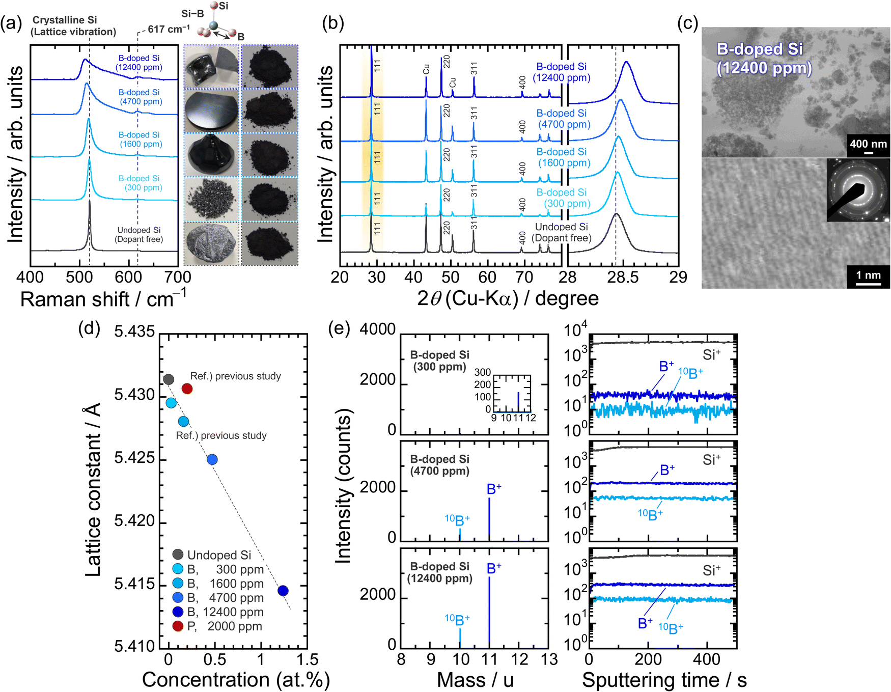 | ||
| Fig. 1 (a) Raman spectra and (b) XRD patterns of pulverized undoped Si (11N) and B-doped Si. The powder was prepared by pulverization of an ingot grown by the Czochralski method. (c) STEM images and SAED pattern of the B-doped Si (12400 ppm). (d) Lattice constant of Si versus impurity concentration (at%). The dopant concentration of B-doped Si was determined by ICP. (e) TOF-SIMS mass spectra and depth profiles of bulk Si samples (B: 600, 4700, and 12400 ppm). For TOF-SIMS, Bi was the primary ion source (30 keV, 100 × 100 μm2) and a low energy sputter beam (1 keV, 300 × 300 μm2) of O2 was used for the depth analysis of B-doped Si samples. | ||
To rigorously investigate the effects of B-doping on the electrochemical lithiation/delithiation of Si in a composite electrode, the particle size (average: 3 μm) and size distribution of the active material powder were adjusted by mechanical milling (Fig. S1 and S2, ESI†). The smaller the particle size, the better the cyclability of the Si-based electrodes should be.7 However, in that case, it is expected to be difficult to determine whether the improved cycle performance is due to the impurity doping or the fine particle sizes. Therefore, we first examined the effect of B dopant concentration using relatively large particles. Fig. 2a compares the initial charge–discharge (lithiation–delithiation) profiles in 1 M LiPF6/EC:DEC under galvanostatic conditions with a constant current density of 358 mA g−1 (0.1C). At the first cycle, voltage plateaus associated with a two-phase reaction of Li–Si alloying/dealloying are observed below 0.125 V and above 0.4 V, respectively, and the onset voltages of lithiation for the B-doped Si are higher than that of the undoped Si irrespective of the B concentration. The lithiation capacity of the undoped Si at which the voltage reached 0.1 V (vs. Li/Li+) is 550 mA h g−1, whereas the capacities of the B-doped Si are 920, 1250, 1090, and 940 mA h g−1 for 300, 1600, 4700, and 12400 ppm, respectively (Fig. S3 and S4, ESI†). The reduction in the overvoltage due to B doping mainly originates from a drastic decrease in the electrical resistivity from ∼108 mΩ cm (undoped Si) to 0.3 mΩ cm (12400 ppm-B-doped Si) (Table S1, ESI†). The favorable kinetics for Li insertion into Si is also responsible for the higher onset voltages; the experimental results using Si wafers reported by Greeley and Gewirth et al. revealed that the Li insertion into Si occurs at a higher potential in n-type Si (dopant: B) than in p-type Si (P), regardless of the (100) and (111) crystal surfaces, which was supported by their DFT calculations.30 On the (111) surface, the p-type Si allowed lithiation at a potential of 0.54 V higher than that of the n-type Si. Although not up to the potential difference observed in the wafer electrodes, the kinetics of lithiation are clearly enhanced by B-doping even in the system of slurry-type composite electrodes. Indeed, we have previously demonstrated using galvanostatic intermittent titration technique (GITT) measurements that the Li diffusion coefficient (DLi) in the B-doped Si (1600 ppm) is twice as large as that of the P-doped Si (2000 ppm).43 On the other hand, the onset voltages for lithiation and Li–Si alloying capacities are not completely dependent on the electrical resistivities of the B-doped Si, that is, B dopant concentrations; as for the B-doped Si with 12400 ppm, which has the lowest electrical resistivity in this work, the lithiation capacity is smaller than that of the undoped Si, even though B doping allows lithiation to proceed at higher potential compared with that of the undoped Si. It is presumed that this is the result of the negative influence of the heavy B-doping, in which lattice contraction causes a decrease in Li-ion conduction, rather than the positive effect of the improved electronic conductivity. Considering the theoretical capacity loss, the initial charge and discharge capacities obtained from 12400-B-doped Si are relatively small. These results indicate that B is electrochemically inactive. The DLi in the 12400 ppm-B-doped Si at the second lithiation cycle (Li0.112Si) determined by the GITT using a three-electrode cell is indeed only about 70% of the 1600 ppm-B-doped Si (4.0 × 10⁻¹⁴ cm2 s−1).37,43 This is supported by the fact that the B-doped Si of 12400 ppm causes the largest charge transfer resistance among the B-doped Si samples (Fig. 2b). It is presumed that the shrinkage of the lattice constant due to heavy B substitution reduced the Li diffusion coefficient. Even so, at the lower cut-off voltage of 0.005 V for the first cycle, the lithiated phase was Li15Si4 (Fig. S5, ESI†), regardless of the B dopant concentration. On the other hand, the smallest resistance observed for the 300 ppm-doped Si that was prepared by diluting with Si originates from the polycrystalline structure with grain boundaries being more reactive with Li than single crystalline Si.44 Meanwhile, the alloying/dealloying reactions of Si with Li associated with bond breaking and rearrangement of Si–Si cause the amorphization,1,9 which shifts the lithiation voltages to the higher side, as observed at the second cycle (Fig. S3 and S4, ESI†). In the second lithiation cycle, the 12400 ppm-B-doped Si underwent a large overvoltage compared with others. This is because the lithiation capacity of the 12400 ppm-B-doped Si at the first cycle was smaller than those of the other systems, i.e., the degree of amorphization was smaller. Even after the amorphization, the dopant B atoms in the structures (300, 1600, 4700, and 12400 ppm) were not lost. On the anodic side in the cyclic voltammograms (Fig. S6, ESI†), no overpotential from Li extraction at the subsequent cycle was observed for the B-doped Si, indicating that the high electrical conductivity was still maintained. Furthermore, the vibrations of Si–11B and Si–10B bonds were again detected when each amorphous Si formed after the first delithiation was irradiated by a 532 nm laser with 25 mW for 30 min (Fig. S7, ESI†). Therefore, even in the case of the pulverization and fracture of the active material due to the huge volume change in Si during lithiation/delithiation, the conductive network of the entire electrode structure is expected to be maintained.
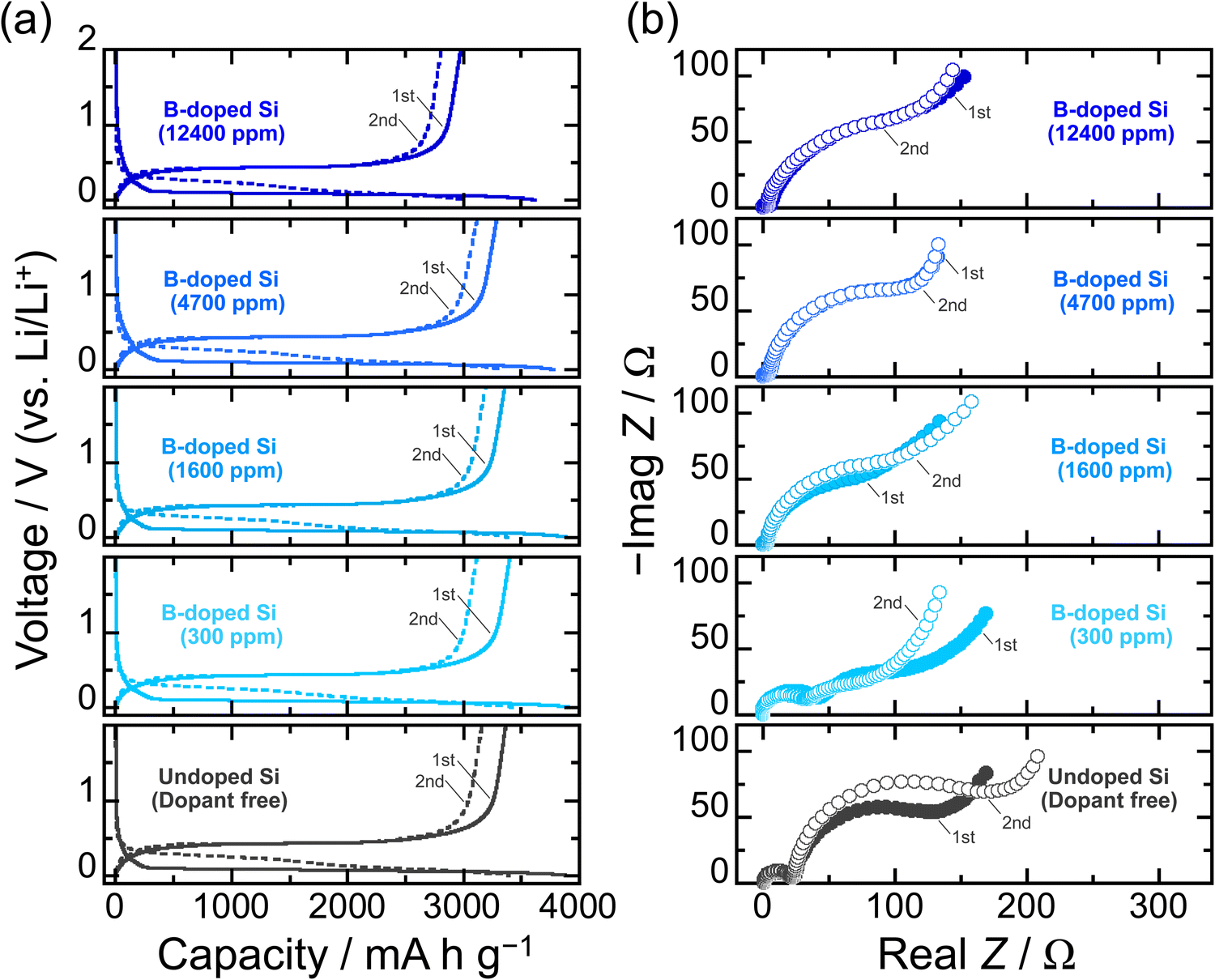 | ||
| Fig. 2 (a) Initial charge/discharge (Li-insertion/extraction) profiles of B-doped Si electrodes in 1 M Li PF6/EC:DEC (50:50vol%) under a constant current density of 358 mA g−1 (0.1C). (b) Nyquist plots of Li/Si electrode cells charged at the lower cut-off voltage. | ||
The effect of B dopant concentration on the cycling performance of Si electrodes was examined under galvanostatic conditions. Fig. 3a represents the dependence of the discharge (delithiation) capacities and Coulomb efficiencies on the cycle number for the B-doped Si electrodes. Despite the enhanced electrical conductivity, the 300 ppm-B-doped Si degraded rather than improved the cycle performance compared to the undoped Si. Since the 300 ppm-B-doped Si is polycrystalline, the mechanical stress gap generated between the different crystal planes and grain boundaries during lithiation is large. The induced mechanical failure earlier than in the single-crystal undoped Si is assumed to be responsible for the accelerated degradation.45,46 The largest capacity decay supports the above, even though the irreversible electrode expansion after the 20th cycle is smaller than those of the other electrodes (Fig. 3b). On the other hand, the 4700 ppm-B-doped Si exhibited the highest electrode performance with a reversible capacity of 1140 mA h g−1 at the 100th cycle. The lithiation/delithiation capacities of the 4700 ppm-B-doped Si at the initial cycle are slightly smaller than those of the 1600 ppm-B-doped Si, meaning that the degree of volume change is also relatively lower. The lower volume change appears to result in the better cycling performance, but rather, the 4700 ppm-B-doped Si actually has larger integrated charge/discharge capacities after 100 cycles (Fig. S8, ESI†). On the other hand, the discharge capacity of the 12400 ppm-B-doped Si dropped to 700 mA h g−1 after the 100th cycle, despite the relatively smaller Li-insertion/extraction capacities than the others. Obrovac et al. systematically investigated the effect of B dopant concentration on electrochemical lithiation/delithiation of an amorphous Si–B thin film prepared by combinatorial sputtering and found that the B is electrochemically inactive with Li.47 In view of this, it is reasonable that the lithiation/delithiation capacities became smaller for the 12400 ppm-B-doped Si, where approximately 1 at% of Si atoms are replaced by B atoms. However, the irreversible electrode expansion after the 20th cycle was remarkable for the 12400 ppm-B-doped Si (Fig. 3b). Considering the bond strengths of Si–Si of 326.8 ± 10 kJ mol−1 and B–Si of 317 ± 12 kJ mol−1,48 the excessive substitution (12400 ppm) of B for Si in the Si structure cannot follow the significant structural change (∼Δ280%) during the Li–Si alloying/dealloying reactions, and it is considered to destroy the Si matrix structure and the electrode structure from a microscopic point of view and from a macroscopic view, respectively. Indeed, the mechanical properties measured by Vickers hardness testing with a load of 50 mN (Fig. 3c) decrease with increasing the B dopant concentration except for the polycrystalline 300 ppm-B-doped Si. The lowest Vickers hardness seems to be closely related to the lowest fracture toughness and thus to the cycle performance of the 12400 ppm-B-doped Si. We do not currently have a clear answer to this question. Given that the hardness of the 4700 ppm-B-doped Si is less than that of the undoped Si, but the cycle performance is better, it is conceivable that the B substitution of up to 12400 ppm would result in a loss of mechanical durability, but a moderate substitution (4700 ppm) would give a good softness and improve the electrode performance. In addition, it is presumable that the nature of the solid electrolyte interphase (SEI) formed on the Si surfaces with these different B concentrations may contribute to the electrode performance,29 but this is a subject for future investigation. In the present study, we added 5 vol% fluoroethylene carbonate (FEC)49 as a film-forming additive to evaluate the electrode performance at a fixed Li-insertion level of 1000 mA h g−1 at 0.1C. This ensures not only that the composition of the surface layer formed in Si is the same regardless of the B concentration, but also that the volume expansion of Si in the entire electrode is the same, thereby making it easier to assess the effects of the B doping on the cycle performance (Fig. 4). In the 12400 ppm-B-doped Si, the limitation of the Li insertion amount led to a slight improvement in performance compared to the undoped Si due to its higher electrical conductivity, but the capacity degraded after less than 100 cycles. This again suggests that the excessive B substitution reduces the fracture toughness. On the other hand, the advantage of the 4700 ppm-B-doped Si was demonstrated when FEC was added and the lithiation capacity was restricted, achieving a reversible capacity of 1000 mA h g−1 for up to ca. the 280th cycle. The explored present study, which shows that the impurity doping by the Cz method can provide electrical conductivity and mechanical durability to the active material matrix itself, is expected to contribute greatly to the research and development of Si negative electrodes for liquid-type as well as all-solid-state batteries.
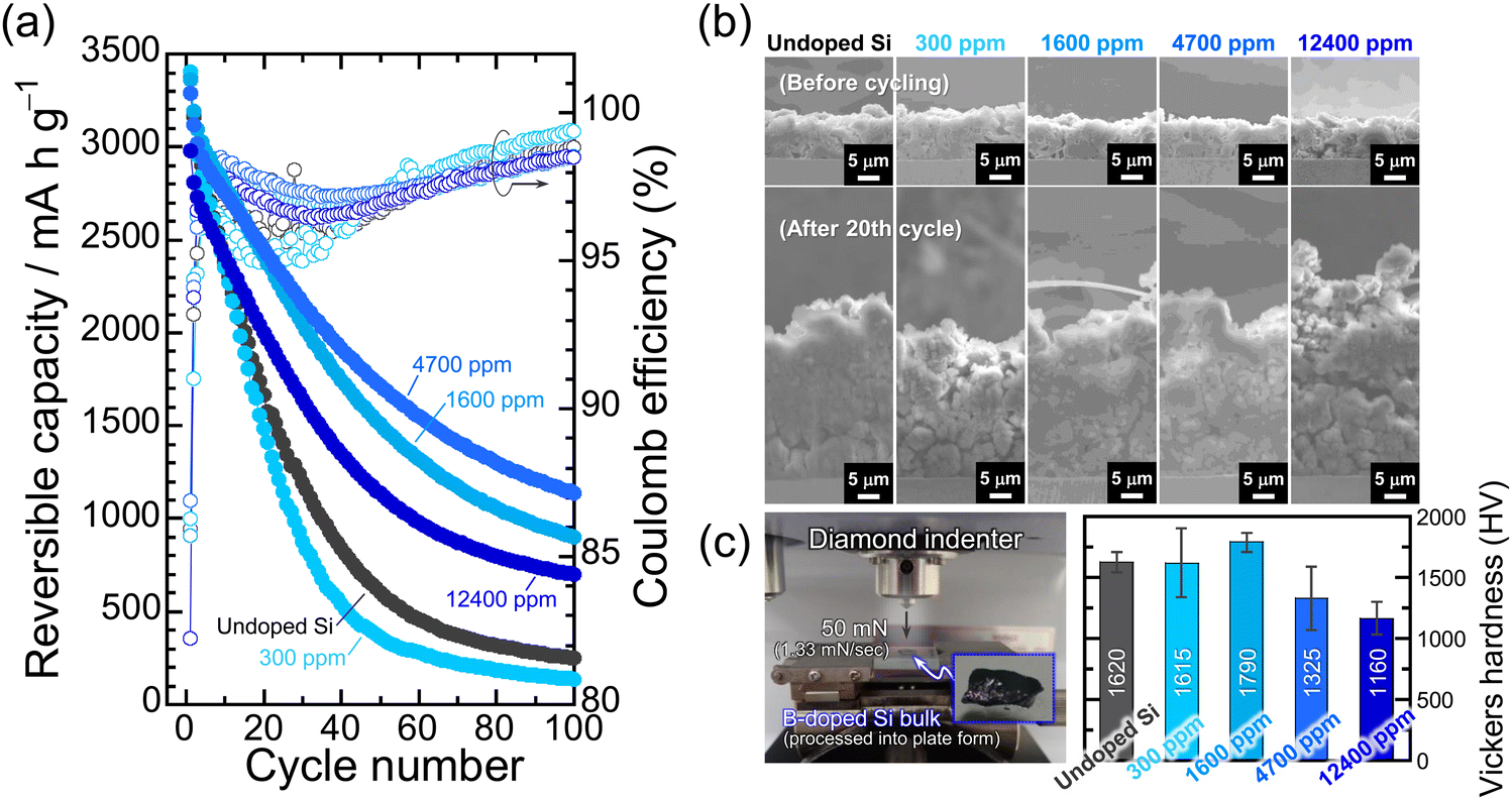 | ||
| Fig. 3 (a) Dependence of the discharge capacities and Coulomb efficiencies on cycle number for undoped-Si and B-doped Si electrodes (300, 1600, 4700, and 12400 ppm) at 0.1C. (b) Cross-sectional SEM images of the electrodes before and after the 20th cycle. (c) Vickers hardness of the Si bulk samples. The Vickers hardness was measured using a diamond indenter with a fixed force (load: 50 mN). | ||
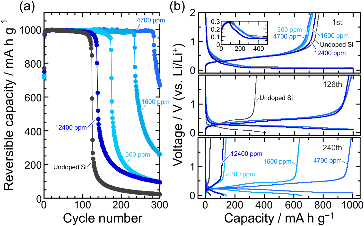 | ||
| Fig. 4 (a) Variation in discharge (Li-extraction) capacity of Si electrodes in 1 M LiPF6/EC:DEC with 5 vol% FEC versus number of cycles at a fixed Li-insertion level of 1000 mA h g−1. (b) Charge/discharge curves of the Si electrodes at the first, 126th, and 240th cycles. Inset: enlarged view of the first charge−discharge curves of Si-based electrodes. | ||
4. Conclusions
We evaluate the electrochemical lithiation/delithiation properties of Si heavily doped with B (∼12400 ppm) synthesized using the Czochralski method. The TOF-SIMS measurements demonstrated that the dopant concentrations of B as an impurity were homogeneous against the depth direction and the lattice constants decreased with increasing the concentration. Although the first lithiation voltages of the B-doped Si (p-type) were thermodynamically favorable compared with that of the undoped Si irrespective of the dopant concentration, the B substitution resulted in a decrease in the lithiation/delithiation capacities. This shows that B is electrochemically inactive with Li. The Vickers hardness testing revealed that the heavy B doping (∼12400 ppm) caused Si to lose mechanical durability, resulting in lower electrode performance than those of the 1600 ppm- and the 4700 ppm-doped Si, despite the highest electrical conductivity. The 4700 ppm-doped Si exhibited the best electrode performance with a reversible capacity of 1140 mA h g−1 at the 100th cycle and 1000 mA h g−1 at the 280th cycle without and with the conditions of limiting charge capacity, respectively. The results indicate that the moderate B doping (4700 ppm) not only imparts high electrical conductivity but also a softness to Si to relax the stress induced by the significant volume change during Li–Si alloying and dealloying reactions.
Conflicts of interest
The authors declare no competing financial interest.Acknowledgements
This work was supported by a Grant-in-Aid for Scientific Research (B) (20H02840) and Early-Career Scientists (18K14317) from the Japan Society for the Promotion of Science (JSPS).References
- B. Key, M. Morcrette, J.-M. Tarascon and C. P. Grey, J. Am. Chem. Soc., 2011, 133, 503 CrossRef CAS PubMed.
- T. T. Truong, Y. Qin, Y. Ren, Z. Chen, M. K. Chan, J. P. Greeley, K. Amine and Y. Sun, Adv. Mater., 2011, 23, 4947 CrossRef CAS PubMed.
- S. R. Gowda, V. Pushparaj, S. Herle, G. Girishkumar, J. G. Gordon, H. Gullapalli, X. Zhan, P. M. Ajayan and A. L. Reddy, Nano Lett., 2012, 12, 6060 CrossRef CAS PubMed.
- H. Wu, G. Chan, J. W. Choi, I. Ryu, Y. Yao, M. T. McDowell, S. W. Lee, A. Jackson, Y. Yang, L. Hu and Y. Cui, Nat. Nanotechnol., 2012, 7, 310 CrossRef CAS PubMed.
- T. D. Hatchard and J. R. Dahn, J. Electrochem. Soc., 2004, 151, A838 CrossRef CAS.
- M. N. Obrovac and L. Christensen, Electrochem. Solid-State Lett., 2004, 7, A93 CrossRef CAS.
- X. H. Liu, L. Zhong, S. Huang, S. X. Mao, T. Zhu and J. Y. Huang, ACS Nano, 2012, 6, 1522 CrossRef CAS PubMed.
- M. Shimizu, H. Usui, K. Matsumoto, T. Nokami, T. Itoh and H. Sakaguchi, J. Electrochem. Soc., 2014, 161, A1765 CrossRef.
- M. Shimizu, H. Usui, T. Suzumura and H. Sakaguchi, J. Phys. Chem. C, 2015, 119, 2975 CrossRef CAS.
- Y. Ma, J. Ma and G. Cui, Energy Storage Mater., 2019, 20, 146 CrossRef.
- C. Zhang, L. Gu, N. Kaskhedikar, G. Cui and J. Maier, ACS Appl. Mater. Interfaces, 2013, 5, 12340 CrossRef CAS PubMed.
- H. Pan, Z. Xu, Z. Wei, X. Liu, M. Xu, C. Zong, W. Li, G. Cui, L. Cao and Q. Wang, ACS Appl. Mater. Interfaces, 2022, 14, 33315 CrossRef CAS PubMed.
- N. Ohta, S. Kimura, J. Sakabe, K. Mitsuishi, T. Ohnishi and K. Takada, ACS Appl. Energy Mater., 2019, 2, 7005 CrossRef CAS.
- R. Miyazaki, N. Ohta, T. Ohnishi and K. Takada, J. Power Sources, 2016, 329, 41 CrossRef CAS.
- V. P. Phan, B. Pecquenard and F. Le Cras, Adv. Funct. Mater., 2012, 22, 2580 CrossRef CAS.
- R. Miyazaki, N. Ohta, T. Ohnishi, I. Sakaguchi and K. Takada, J. Power Sources, 2014, 272, 541 CrossRef CAS.
- J. Pan, H. Peng, Y. Yan, Y. Bai, J. Yang, N. Wang, S. Dou and F. Huang, Energy Storage Mater., 2021, 43, 165 CrossRef.
- G. Masetti, M. Severi and S. Solmi, IEEE Trans. Electron Devices, 1983, 30, 764 Search PubMed.
- N. Ding, J. Xu, Y. X. Yao, G. Wegner, X. Fang, C. H. Chen and I. Lieberwirth, Solid State Ion., 2009, 180, 222 CrossRef CAS.
- J. Xie, N. Imanishi, T. Zhang, A. Hirano, Y. Takeda and O. Yamamoto, Mater. Chem. Phys., 2010, 120, 421 CrossRef CAS.
- L. Xue, G. Xu, Y. Li, S. Li, K. Fu, Q. Shi and X. Zhang, ACS Appl. Mater. Interfaces, 2013, 5, 21 CrossRef CAS PubMed.
- X. Ding, H. Wang, X. Liu, Z. Gao, Y. Huang, D. Lv, P. He and Y. Huang, RSC Adv., 2017, 7, 15694 RSC.
- G. Lv, B. Zhu, X. Li, C. Chen, J. Li, Y. Jin, X. Hu and J. Zhu, ACS Appl. Mater. Interfaces, 2017, 9, 44452 CrossRef CAS PubMed.
- S. Huang, L. Z. Cheong, D. Wang and C. Shen, ACS Appl. Mater. Interfaces, 2017, 9, 23672 CrossRef CAS PubMed.
- R. Yi, J. Zai, F. Dai, M. L. Gordin and D. Wang, Electrochem. Commun., 2013, 36, 29 CrossRef CAS.
- J. S. Kim, W. Choi, D. Byun and J. K. Lee, Solid State Ion., 2012, 212, 43 CrossRef CAS.
- Z. Yang, D. Wang, F. Li, H. Yue, D. Liu, X. Li, L. Qiao and D. He, Mater. Lett., 2014, 117, 58 CrossRef CAS.
- J.-H. Noh, K.-Y. Lee and J.-K. Lee, Trans. Nonferrous Met. Soc. China, 2009, 19, 1018 CrossRef CAS.
- W. McSweeney, O. Lotty, C. Glynn, H. Geaney, J. D. Holmes and C. O’Dwyer, Electrochim. Acta, 2014, 135, 356 CrossRef CAS.
- B. R. Long, M. K. Y. Chan, J. P. Greeley and A. A. Gewirth, J. Phys. Chem. C, 2011, 115, 18916 CrossRef CAS.
- Y. Domi, H. Usui, M. Shimizu, Y. Kakimoto and H. Sakaguchi, ACS Appl. Mater. Interfaces, 2016, 8, 7125 CrossRef CAS PubMed.
- M. Lee, D. Yoon, U. J. Lee, N. Umirov, A. Mukanova, Z. Bakenov and S.-S. Kim, Front. Chem., 2019, 7, 389 CrossRef CAS PubMed.
- S. Rousselot, M. Gauthier, D. Mazouzi, B. Lestriez, D. Guyomard and L. Roué, J. Power Sources, 2012, 202, 262 CrossRef CAS.
- D. Lau, C. A. Hall, S. Lim, J. A. Yuwono, P. A. Burr, N. Song and A. Lennon, ACS Appl. Energy Mater., 2020, 3, 1730 CrossRef CAS.
- X. Han, Z. Zhang, H. Chen, L. Luo, Q. Zhang, J. Chen, S. Chen and Y. Yang, J. Mater. Chem. A, 2021, 9, 3628 RSC.
- M. Chen, B. Li, X. Liu, L. Zhou, L. Yao, J. Zai, X. Qian and X. Yu, J. Mater. Chem. A, 2018, 6, 3022 RSC.
- M. Shimizu, K. Kimoto, T. Kawai, T. Taishi and S. Arai, ACS Appl. Energy Mater., 2021, 4, 7922 CrossRef CAS.
- T. Taishi, X. Huang, M. Kubota, T. Kajigaya, T. Fukami and K. Hoshikawa, Mater. Sci. Eng. B, 2000, 72, 169 CrossRef.
- T. Taishi, Y. Ohno and I. Yonenaga, J. Cryst. Growth, 2014, 393, 42 CrossRef CAS.
- N. Fukata, Adv. Mater., 2009, 21, 2829 CrossRef CAS.
- S. Zhou, X. Pi, Z. Ni, Q. Luan, Y. Jiang, C. Jin, T. Nozaki and D. Yang, Part. Part. Syst. Charact., 2015, 32, 213 CrossRef CAS.
- G. Celotti, D. Nobili and P. Ostoja, J. Mater. Sci., 1974, 9, 821 CrossRef CAS.
- W. Weppner and R. A. Huggins, J. Electrochem. Soc., 1977, 124, 1569 CrossRef CAS.
- M. Gauthier, D. Mazouzi, D. Reyter, B. Lestriez, P. Moreau, D. Guyomard and L. Roué, Energy Environ. Sci., 2013, 6, 2145 RSC.
- M. Sternad, M. Förster and M. Wilkening, Sci. Rep., 2016, 6, 31712 CrossRef CAS PubMed.
- X. Kong, Y. Zhang, S. Peng, J. Zeng and J. Zhao, ACS Sustainable Chem. Eng., 2020, 8, 14938 CrossRef CAS.
- H. Liu, M. Zhu, Z. Du and M. N. Obrovac, J. Electrochem. Soc., 2015, 163, A192 CrossRef.
- Z. Zeng, X. Ma, J. Chen, Y. Zeng, D. Yang and Y. Liu, J. Appl. Phys., 2010, 107, 123503 CrossRef.
- H. Nakai, T. Kubota, A. Kita and A. Kawashima, J. Electrochem. Soc., 2011, 158, A798 CrossRef CAS.
Footnote |
| † Electronic supplementary information (ESI) available: SEM images and particle size distribution of B-doped Si; llithiation/delithiation profiles of Si electrodes during galvanostatic charge/discharge tests (PDF). See DOI: https://doi.org/10.1039/d3ya00021d |
| This journal is © The Royal Society of Chemistry 2023 |