
 Open Access Article
 This Open Access Article is licensed under a Creative Commons Attribution-Non Commercial 3.0 Unported Licence
Surface etching to tune the behaviours of photogenerated charges on a decahedron BiVO4 crystal for efficient photocatalysis†
Yue
Zhao‡
a,
Shunning
Li‡
 b,
Hui
Li
a,
Bin
Zeng
a,
Haibo
Chi
a,
Yihuan
Wang
a,
Huangzhao
Wei
a,
Feng
Pan
*b and
Rengui
Li
*a
b,
Hui
Li
a,
Bin
Zeng
a,
Haibo
Chi
a,
Yihuan
Wang
a,
Huangzhao
Wei
a,
Feng
Pan
*b and
Rengui
Li
*a
aState Key Laboratory of Catalysis, Dalian National Laboratory for Clean Energy, Dalian Institute of Chemical Physics Chinese Academy of Sciences, Zhongshan Road 457, Dalian 116023, China. E-mail: rgli@dicp.ac.cn
bSchool of Advanced Materials, Peking University, Shenzhen Graduate School, Shenzhen, China. E-mail: panfeng@pkusz.edu.cn
First published on 14th July 2023
Abstract
Achieving spatial charge separation between different facets on a single crystal is one of the most efficient approaches to improve the charge separation efficiency of semiconductor-based photocatalysts. However, how the exposed facets affect spatial charge separation is still elusive, and the control of the behaviors of photogenerated charges remains challenging. In this work, decahedron BiVO4 was chosen as a model photocatalyst, and a surface etching strategy using sodium hydroxide solution was employed, resulting in selective etching of the {010} facets while the {110} facets remained intact. The distribution of photogenerated electrons was found to be gradually transferred from the etched {010} facets to the {110} facets, which was accompanied by the reverse transfer of photogenerated holes. This result indicates that the distribution of photogenerated electrons and holes on different facets can be precisely modulated by tuning the surface properties of exposed facets. This modulation, enabled by the surface etching treatment herein, could give rise to much improved photocatalytic performance of decahedron BiVO4 for the degradation of various aromatic and heteroaromatic environmental pollutants. This work provides a feasible strategy to modulate the charge behaviors of semiconductors, which will be instructive in constructing efficient photocatalysts for solar energy conversion.
Environmental significanceCurrently, human society is facing critical challenges related to energy and environmental pollution. Solar energy conversion through semiconductor-based photocatalysis processes has been identified as a potential solution to these problems, but the total utilization of solar energy is limited by poor charge separation. To overcome this limitation, the strategy of spatial charge separation has been suggested, but the underlying mechanisms require further investigation. Herein, a method has been developed to modulate the behavior of photogenerated charges, not only providing insights into the behavior of semiconductor charges, but also improving the degradation performance of various aromatic and heteroaromatic environmental pollutants. This work outlines an effective approach to control the charge behavior of semiconductors, and is valuable for developing efficient photocatalyst systems. |
Introduction
Semiconductor-based photocatalysts are widely studied for photocatalytic solar energy conversion, including water splitting, CO2 reduction, environmental pollutant degradation, organic synthesis, etc.1–13 However, many photocatalysts still suffer from poor charge separation efficiency and sluggish surface reaction kinetics during photocatalytic reaction processes.14–19 To improve the charge separation efficiency, various strategies have been exploited. For example, fabrication of p–n junctions can promote charge separation due to the built-in electric field from n-type to p-type photocatalysts.20,21 Heterophase junctions formed between different crystal phases of semiconductors have also been demonstrated to be useful in facilitating charge separation based on the energy band difference.22,23 Apart from the junction strategies, spatial charge separation between different facets of a single crystal has been widely demonstrated to facilitate charge separation in photocatalysis. Our previous studies have proved that photogenerated electrons and holes can be spatially separated between different facets of BiVO4, which can efficiently facilitate the separation of photogenerated charges and greatly improve photocatalytic performance.24,25 Besides, spatial charge separation between different facets was also achieved in a SrTiO3 single crystal, which possesses high symmetry.26 This strategy was further applied to a variety of semiconductor crystals successfully (e.g., TiO2, Cu2O, and GaN),27,28 demonstrating the crucial role of exposed facets in spatial charge separation in photocatalysis.Spatial charge separation between different facets is proved to be closely related to the exposed facets of a photocatalyst crystal, but it is still unclear how the exposed facets affect the spatial charge separation.15,25,29,30 Specifically, it remains controversial whether the selective distribution of photogenerated electrons and holes is determined by the nature of the crystal or by the properties of the surface. Although it is reported that the spatial charge separation properties can be achieved after constructing the anisotropy of photocatalyst crystals, the spatial charge separation may also be affected by the surface properties.31–33 For example, the regulation of pH could modulate the surface charge characteristics of Bi4TaO8Cl and SrTiO3 with anisotropic facets, such as the isoelectric point, which can induce selective deposition of the cocatalyst on different exposed facets, and further achieve spatial charge separation between different exposed facets.34,35 While these modulations of the crystal surface mainly focus on the surface charge property adjustment and introducing surface modification, studies on intrinsic surface structure regulation are still lacking, especially regarding the regulation of charge distribution on photocatalyst crystals with intrinsic charge separation properties.
In this work, decahedron BiVO4, which shows spatial photogenerated charge separation properties between different facets, was employed as an example to investigate how the surface structure affects the distribution of photogenerated charges. We observed that the {010} facets of BiVO4 were preferably etched using NaOH solution based on the different acid–base stability between {010} and {110} facets, while the {110} facets remained intact. The distribution of photogenerated electrons was changed from the {010} facets to {110} facets, while the photogenerated holes moved from the {110} facets to the etched region. We also demonstrated that the BiVO4 photocatalysts with surface etching show greatly improved photocatalytic degradation of various aromatic and heteroaromatic environmental pollutants, such as methyl blue, methyl orange and m-cresol, as compared to untreated BiVO4. This work provides a potential way to modulate photogenerated charge properties of semiconductor photocatalysts for efficient photocatalysis.
Experimental
Synthesis of a decahedron BiVO4 crystal
A decahedron BiVO4 crystal was synthesized according to our previous report.15,36 10.0 mmol Bi(NO3)3·5H2O and 10.0 mmol NH3VO3 were dissolved respectively in 30 mL nitric acid solution (2.0 M). The above solutions were mixed after complete dissolution. Then the pH value of the mixed solution was adjusted to 0.5 with ammonia solution (25–28 wt%) under vigorous stirring. After stirring for 2 hours at room temperature, a light yellow BiVO4 slurry was obtained. Subsequently, the slurry was transferred to a Teflon-lined stainless-steel autoclave with a capacity of 100 mL, and treated at 473 K for 12 hours in an oven. Finally, a yellow precipitate was obtained. The obtained precipitate was washed with ultrapure water and dried at 353 K overnight. The obtained BiVO4 powder was named a decahedron BiVO4 crystal.Preparation of an etched BiVO4 crystal
60 mg decahedron BiVO4 crystal was dispersed in 10 mL NaOH solutions with different concentrations (0, 0.1 M, 0.2 M, 0.6 M, 1.0 M, 2.0 M, 3.0 M, and 4.0 M), and stirred for 2.5 hours. Then the obtained precipitates were separated by centrifugation and washed with ultrapure water several times. Finally, the precipitates were dried at 353 K overnight.Photo-deposition of metals and/or oxides
Characterization
BiVO4 samples were characterized by X-ray power diffraction (XRD) on a Rigaku SmartLab powder diffractometer. A scan rate of 20° min−1 was applied to record the XRD patterns in the range of 20–60° at a step size of 0.01°. UV-visible (UV-vis) diffuse reflectance spectra were recorded on a UV-vis spectrophotometer (JASCO V-550) equipped with an integrating sphere. The morphologies were examined by scanning electron microscopy (SEM, Quanta 200 FEG, FEI). The binding energies were determined by X-ray photoelectron spectroscopy (XPS, Thermo Escalab 250Xi, a monochromatic Al Kα X-ray source), and calibrated by using the C 1s peak (284.6 eV) for each sample. Electron paramagnetic resonance (EPR) experiments were carried out on a Bruker A200 spectrometer equipped with an ER 4119HS-LC resonator.Photocatalytic organic molecule degradation reaction
The degradation performance was evaluated in a side irradiation reactor (100 mL) using a 300 W Xe lamp (Ushio-CERMAX LX300). Normally, 100 mg photocatalyst was dispersed in the organic molecule solution (methyl blue, methyl orange, and m-cresol) and stirred in the dark for 30 min. After different times, the light source was turned on, and 5 mL of the suspension was taken out and filtered for later detection. The concentrations of residual methyl blue and methyl orange were determined through the spectrophotometric method using a UV-vis spectrophotometer (JASCO V-550). And the concentrations of m-cresol were detected by high-performance liquid chromatography (HPLC, lc-2030 plus, Shimadzu). The concentrations of the total organic carbon (TOC) were determined by using a total organic carbon analyzer (TOC-VCPN, Shimadzu).Calculation methods
First principles calculations were performed using the plane-wave based density functional theory (DFT) method as implemented in the Vienna Ab initio Simulation Package (VASP).37,38 The electron–core interactions were treated in the projector augmented wave method with a kinetic energy cutoff of 520 eV.39 The Perdew–Burke–Ernzerhof generalized gradient approximation was employed with Hubbard U corrections (PBE+U), and spin polarization was taken into consideration in all calculations.40 An effective U value of 3.2 eV for the V element was taken from the literature.41k-Point meshes of at least 1000/(the number of atoms per cell) within the Monkhorst–Pack scheme were used.42 Geometry optimization was performed until the forces on all atoms were smaller than 0.02 eV Å−1. The surface hydrogenation energy was calculated according to the following equation: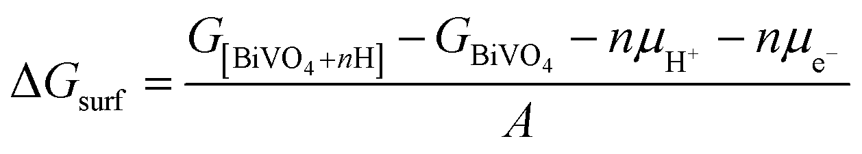 | (1) |
μH+ = 1/2GH2 − kBT![[thin space (1/6-em)]](https://www.rsc.org/images/entities/char_2009.gif) ln[H+] = 1/2GH2 − 2.303kBT × pH ln[H+] = 1/2GH2 − 2.303kBT × pH | (2) |
Results and discussion
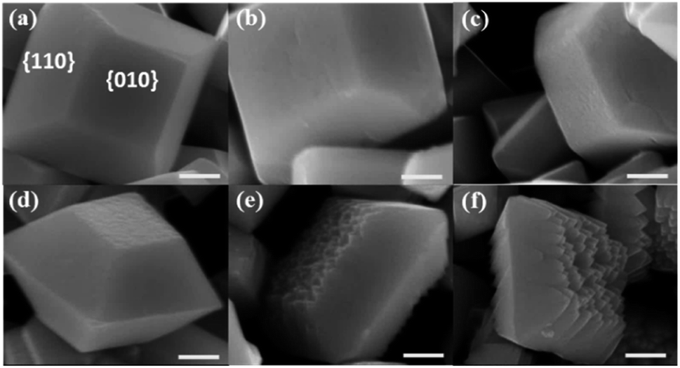
First, BiVO4 crystals with decahedron morphology were synthesized via a hydrothermal process.15,36 As shown in Fig. S1,† smooth {010} and {110} facets are selectively exposed on the synthesized BiVO4 crystals. The distribution of photogenerated electrons and holes was confirmed through in situ photochemical deposition of Au and MnOx. As shown in Fig. S1b and c,† Au nanoparticles and MnOx species are selectively deposited on the {010} and {110} facets of the BiVO4 crystal, respectively, indicating that spatial charge separation between the {010} and {110} facets took place in the as-prepared decahedron BiVO4 crystals.15,24,25 X-ray diffraction (XRD) analysis confirms the monoclinic scheelite phase and high crystallinity of the as-prepared BiVO4 (Fig. S2†).Surface etching enables the tuning of the surface properties, including structure and composition. For example, it is widely accepted that the {001} facets of anatase TiO2 crystals can be controllably etched by introducing HF acid due to the stability difference of the exposed facets.43 To investigate the stability difference between the {010} and {110} facets for decahedron BiVO4, theoretical simulation of pristine surfaces was conducted first (Fig. 1a and b). Then, the {010} and {110} facets were treated under basic conditions to form hydrogen-rich surfaces (Fig. 1c and d). Different pH values were applied to check the stability of the {010} and {110} facets. As shown in Fig. 1e, the hydrogenation energy of the {010} facets increases more rapidly than that of the {110} facets as a function of the pH value, meaning that the hydrogenated {010} facets are more unstable than the {110} facets under basic conditions.
 | ||
| Fig. 1 Theoretical simulation of the (a) {010} facet, (b) {110} facet, (c) hydrogen-rich {010} facet and (d) hydrogen-rich {110} facet of decahedron BiVO4. (e) Effect of the pH value on the stability of the hydrogen-rich {010} and {110} facets of decahedron BiVO4. | ||
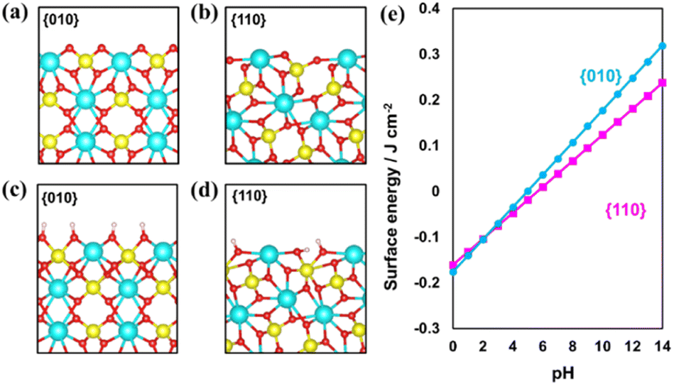
According to the theoretical calculation, different concentrations of NaOH solution were used to treat the as-prepared decahedral BiVO4 crystals. Scanning electron microscope (SEM) images of the obtained BiVO4 samples show that the {010} facets of decahedron BiVO4 were preferably etched in NaOH solution, while the {110} facets maintain smooth (Fig. 2). Meanwhile, the etching degree can be controlled by adjusting the concentration of NaOH solution, but all the BiVO4 samples maintain the monoclinic scheelite phase (Fig. S3†). When the concentration of NaOH was more than 3.0 M, weak characteristic peaks corresponding to cubic Bi2O3 appear, which were also confirmed by the observed cubic crystals in SEM images (Fig. S4†). A relatively low concentration of NaOH etching does not change the bulk structure of BiVO4 crystals, and the light absorption ranges were also maintained (Fig. S5†).
 | ||
| Fig. 2 SEM images of BiVO4 samples etched in NaOH solution with different concentrations. (a) 0 M; (b) 0.1 M; (c) 0.2 M; (d) 1.0 M; (e) 2.0 M and (f) 3.0 M. Scale bar, 500 nm. | ||
To check the distribution of photogenerated electrons of decahedron BiVO4 crystals after NaOH etching, in situ photoreduction-deposition of Au particles was conducted.24,25 SEM images show that Au nanoparticles are selectively deposited on the {010} of decahedron BiVO4 crystals without NaOH etching (Fig. 3a), which is similar to our previous results. When BiVO4 was etched in NaOH solution with a low concentration, Au nanoparticles are still mainly deposited on the etched region of the {010} facets, but a small amount of Au nanoparticles began to appear on the {110} facets (Fig. 3b and S6a†). When the concentration of NaOH increases to 1.0 M, the number of Au nanoparticles in the etched region gradually decreases, but an obvious increase on the {110} facets was observed (Fig. S6b†). When the concentration of NaOH further reaches 2.0 M, almost all the Au nanoparticles are selectively deposited on the {110} facets, but can rarely be observed in the etched region (Fig. 3c and S6c†). It reveals that the dominant distribution of photogenerated electrons can be changed from the {010} facets to {110} facets after surface etching in NaOH solution.
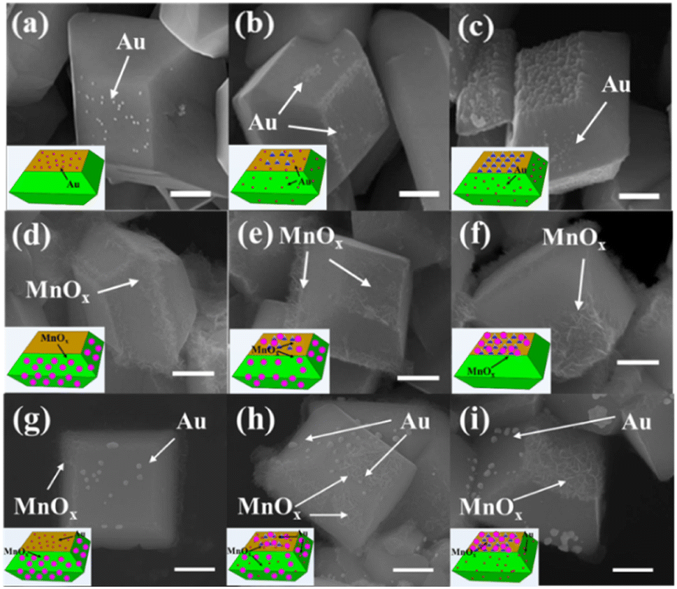 | ||
| Fig. 3 SEM images of etched BiVO4 crystals with photoreduction-deposition of Au (a) without NaOH; (b) 0.6 M; (c) 2.0 M. SEM images of etched BiVO4 crystals with photooxidation-deposition of MnOx (d) without NaOH; (e) 0.6 M (f) 2.0 M. SEM images of etched BiVO4 crystals with photo-deposition of Au and MnOx (g) without NaOH; (h) 0.6 M (i) 2.0 M. The contents of the deposited Au and MnOx are 0.5 wt% and 2.0 wt%, respectively. Scale bar, 500 nm. | ||
Similarly, the distribution of photogenerated holes of decahedron BiVO4 crystals was also investigated by in situ photooxidation deposition.24,25 On decahedron BiVO4 crystals without etching, photooxidation deposition of MnOx species using Mn2+ ions dominantly takes place on the {110} facets (Fig. 3d). However, the MnOx species appear in the etched region of the {010} facets after NaOH etching, and the amount of MnOx species increases with increasing concentration of NaOH (Fig. 3e and S6d, e†). When the concentration of NaOH reaches 2.0 M, the MnOx species mainly appear in the etched region, but rarely on the {110} facets (Fig. 3f and S6f†), indicating that the distribution of photogenerated holes was completely reversed from the {110} facets to the etched region after surface etching with NaOH.
To further confirm the distribution changes of photogenerated electrons and holes on different facets, both photoreduction deposition of Au nanoparticles and oxidation deposition of MnOx species were simultaneously conducted on the etched BiVO4 crystals. As shown in Fig. 3g, Au nanoparticles and MnOx species are selectively deposited on the {010} and {110} facets of decahedron BiVO4 crystals. After surface etching, Au nanoparticles and MnOx species are observed on the {110} facets and the etched region of {010} facets, respectively (Fig. 3h and S6g, h†). When the concentration of NaOH was increased to 2.0 M, Au nanoparticles are dominantly deposited on the {110} facets while MnOx species are selectively deposited on the etched region (Fig. 3i and S6i†). It further verifies that when the {010} facets of decahedron BiVO4 are appropriately etched with NaOH, the distribution of photogenerated electrons is transferred from the {010} to {110} facets, while the distribution of photogenerated holes is transferred from the {110} facets to the etched region. In addition, in situ photodeposition of several species, such as Ag, Pt, PbOx and CoOx, further confirms the distribution change of photogenerated charges after surface etching (Fig. S7†).
To investigate the change in the surface structure for etched decahedron BiVO4 crystals, the stability of the surface structure was theoretically evaluated by constructing off-stoichiometric surfaces under basic conditions (Fig. S8 and S9†). The calculation results show that the free energy change to establish Bi deficiency at the surfaces is remarkably lower than that for VO4 deficiency. More importantly, the formation of both Bi and VO4 deficiencies on the {110} facets is much more endothermic than that on the {010} facets, indicating that the {110} facets exhibit considerably higher resistibility to NaOH etching than the {010} facets. In addition, the etching process will not stop on prolonging the treatment time in NaOH solution; meanwhile, individual cubic Bi2O3 crystals were formed (Fig. S4†). If the terminal atom is Bi after surface etching, Bi2O3 will be formed on the surface and block the etching process.44 Therefore, the surface of the etched region is more likely to be made up of VO4 terminal groups. To further verify the above results, 0.1 M HNO3 was used to wipe out the Bi2O3 species of the etched BiVO4 sample and investigate the effect on the photogenerated charge distribution. As shown in Fig. S10,† Au particles and MnOx species were selectively deposited on the {110} facets and the etched region of the etched BiVO4 pretreated with 0.1 M HNO3 solution, respectively, which is consistent with the situation without acid treatment. This means that there is no obvious change in the etched region of BiVO4 after 0.1 M HNO3 solution treatment. These results further indicate that the etched region of BiVO4 is covered by VO4 terminal groups. Moreover, X-ray photoelectron spectroscopy (XPS) was then introduced to investigate the chemical states of decahedron BiVO4 crystals before and after NaOH etching (Fig. S11†). The O 1s spectrum can be fitted to two peaks located at 529.5 and 531.1 eV for both BiVO4 samples. The peak at 529.5 eV can be assigned to O2− species in the lattice (OL).45,46 The peak at 531.1 eV is usually assigned to hydroxyl groups bonded to the metal cations in the oxygen vacancy region (OV) or bridging hydroxyl on the surface (OB).45–48 As no obvious oxygen vacancy signal was observed in electron paramagnetic resonance (EPR) spectra for both BiVO4 samples (Fig. S12†), the peak at 531.1 eV is possibly assigned to OB on the surface. The atomic ratios of OL and OB were also calculated based on the peak area. The atomic ratio of OB in etched BiVO4 is almost twice that of the pristine one (Table S1†). Therefore, it can be concluded that surface etching removes some of the surface Bi atoms, and more oxygen atoms are exposed as the V–OB terminal group in the etched region.
Based on the above results, the distribution of photogenerated electrons and holes on a decahedron BiVO4 crystal before and after NaOH etching is described as shown in Fig. 4. Before NaOH etching, photogenerated electrons and holes are selectively accumulated on the {010} and {110} facets, respectively (Fig. 4a). After NaOH etching, a totally reversed distribution of photogenerated electrons and holes takes place, that is, photogenerated electrons accumulate on the {110} facets while photogenerated holes accumulate in the etched region (Fig. 4b and c). For a decahedron BiVO4 crystal before NaOH etching, a built-in electric field in the space charge region from {010} to {110} facets, caused by the different band bending between {010} and {110} facets, leads to the anisotropic charge distributions between different facets (Fig. 4d).29 After NaOH etching, Bi atoms on the {010} facets are etched off and V–OB terminal groups are exposed gradually. The increase in V–OB terminal groups makes the electronegativity of the etched region increase and further magnifies its upward band bending (Fig. 4e).49 Then the built-in electric field from the {110} facets to the etched region weakens (Fig. 4f), which may be the origin of the reversed photogenerated charge distribution on the etched BiVO4 crystals.
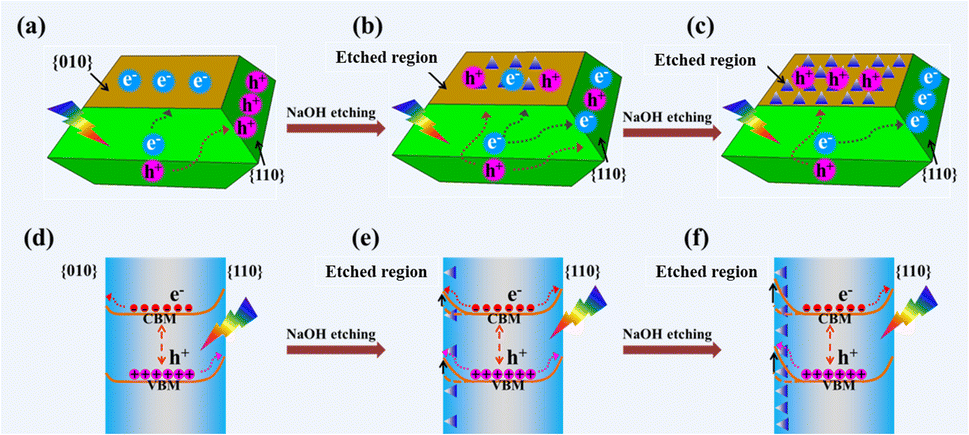 | ||
| Fig. 4 Scheme of the distribution of photogenerated electrons and holes on a decahedron BiVO4 crystal (a) before and (b and c) after NaOH etching. Scheme of different band bendings in the etched region and {110} facets of the decahedron BiVO4 crystal (d) before and (e and f) after NaOH etching and the resulting spatial charge separation. | ||
To investigate how surface etching affects the charge behaviour of photocatalytic reactions, the photocatalytic degradation of different typical pollutants (e.g. methyl blue, methyl orange and m-cresol) on a BiVO4 crystal and the etched BiVO4 crystal treated in 2.0 M NaOH solution for 2.5 h was carried out. As shown in Fig. 5a, the etched BiVO4 crystal shows much higher methyl blue degradation performance than the blank decahedron BiVO4 crystal. Then the reaction kinetics of methyl blue degradation was also examined. As shown in Fig. 5b, the rate constant values follow apparent first order kinetics in agreement with a generally observed Langmuir–Hinshelwood mechanism:
| ln(C0/Ct) = kt |
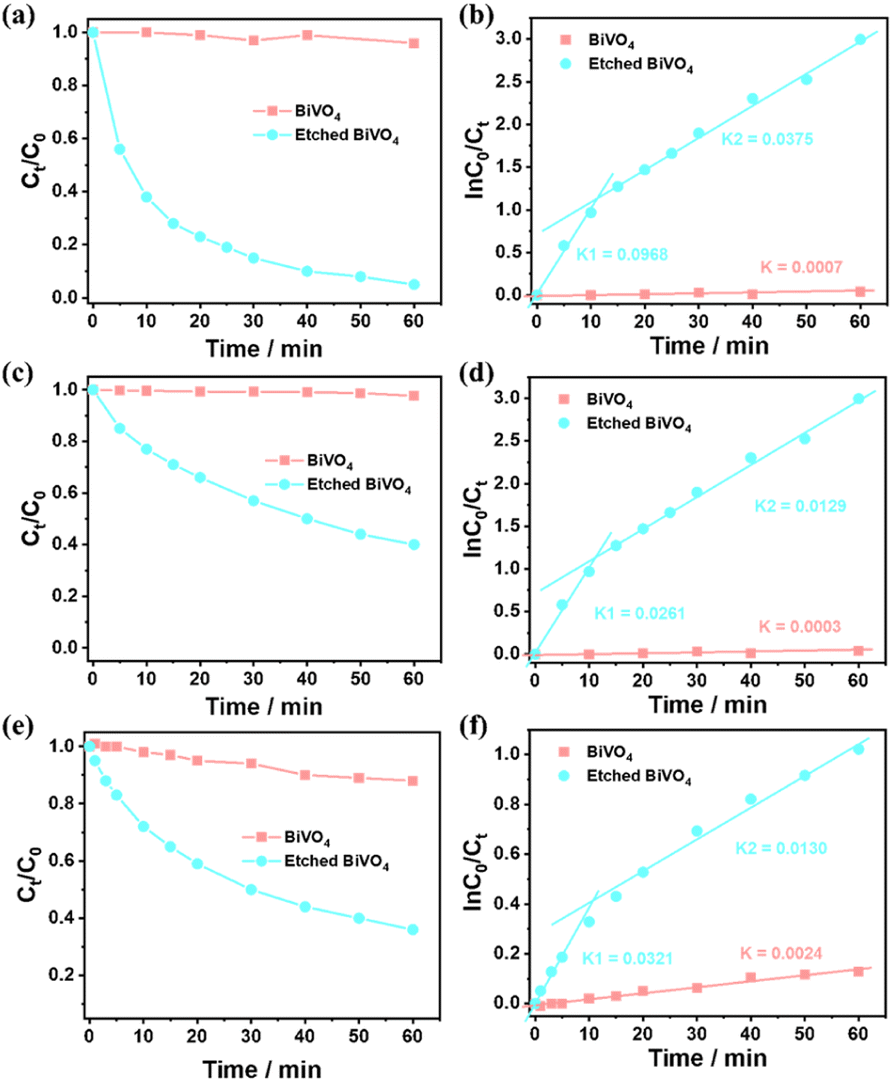 | ||
| Fig. 5 (a) Photocatalytic degradation of methyl blue over a decahedron BiVO4 crystal and etched BiVO4 crystal. (b) Corresponding rate constants of methyl blue degradation from (a). (c) Photocatalytic degradation of methyl orange over a decahedron BiVO4 crystal and etched BiVO4 crystal. (d) Corresponding rate constants of methyl orange degradation from (c). (e) Photocatalytic degradation of m-cresol over a decahedron BiVO4 crystal and etched BiVO4 crystal. (f) Corresponding rate constants of m-cresol degradation from (e). Reaction conditions: catalyst, 200 mg; 10.0 mg L−1 organic molecules, 100 mL; light source, Xe lamp (300 W). The etched BiVO4 crystal represents a BiVO4 crystal treated in 2.0 M NaOH solution for 2.5 h. | ||
Conclusions
In summary, based on the different acid–base stability between the {010} and {110} facets of a decahedron BiVO4 crystal, selective etching of the {010} facets was achieved by using NaOH solution. The distribution of photogenerated electrons was found to be gradually transferred from the {010} facets to the {110} facets, which was accompanied by the reverse transfer of photogenerated holes. This result indicates that the distribution of photogenerated electrons and holes on different facets can be precisely modulated by tuning the surface properties of exposed facets. The reversal in the distribution of photogenerated charges is probably due to the increase in upward surface band bending of etched {010} facets, which is caused by the enhancement of electronegativity of the etched {010} facets due to the surface V–OB terminal groups increasing after NaOH etching. The etched surface of the decahedron BiVO4 crystal shows better performance and great universality for catalytic degradation of aromatic or aromatic heterocyclic structure compounds. This work provides a feasible strategy to modulate the charge behaviours of semiconductors, which will be instructive in constructing efficient photocatalysts for solar energy conversion.Author contributions
Yue Zhao: methodology, validation, formal analysis, writing – original draft. Shunning Li: methodology, formal analysis, writing – review & editing. Hui Li: methodology, validation. Bin Zeng: methodology, formal analysis. Haibo Chi: methodology, formal analysis. Yihuan Wang: methodology, formal analysis. Huangzhao Wei: formal analysis, writing – review & editing. Feng Pan: formal analysis, writing – review & editing, resources. Rengui Li: conceptualization, formal analysis, writing – review & editing, resources, project administration, supervision.Conflicts of interest
There are no conflicts to declare.Acknowledgements
This work was financially supported by the National Key Research and Development Program of China (2021YFA1502300), the National Natural Science Foundation of China (22090033 and 22272165), the Dalian Institute of Chemical Physics, Chinese Academy of Sciences and the Major Science and Technology Infrastructure Project of the Material Genome Big-science Facilities Platform supported by the Municipal Development and Reform Commission of Shenzhen.References
- B. A. Pinaud, J. D. Benck, L. C. Seitz, A. J. Forman, Z. Chen, T. G. Deutsch, B. D. James, K. N. Baum, G. N. Baum, S. Ardo, H. Wang, E. Miller and T. F. Jaramillo, Energy Environ. Sci., 2013, 6, 1983–2002 RSC.
- Q. Wang and K. Domen, Chem. Rev., 2019, 120, 919–985 CrossRef PubMed.
- N. S. Lewis, Science, 2016, 351, 6271 CrossRef PubMed.
- H. L. Wu, M. Y. Qi, Z. R. Tang and Y. J. Xu, J. Mater. Chem. A, 2023, 11, 3262–3280 RSC.
- M. G. Walter, E. L. Warren, J. R. McKone, S. W. Boettcher, Q. X. Mi, E. A. Santori and N. S. Lewis, Chem. Rev., 2010, 110, 6446–6473 CrossRef CAS PubMed.
- F. Zhang, Y. H. Li, J. Y. Li, Z. R. Tang and Y. J. Xu, Environ. Pollut., 2019, 253, 365–376 CrossRef CAS.
- N. S. Lewis and D. G. Nocera, Proc. Natl. Acad. Sci. U. S. A., 2006, 103, 15729–15735 CrossRef CAS PubMed.
- X. Chen, L. Liu, P. Y. Yu and S. S. Mao, Science, 2011, 331, 746–750 CrossRef CAS PubMed.
- X. Chen, S. Shen, L. Guo and S. S. Mao, Chem. Rev., 2010, 110, 6503–6570 CrossRef CAS PubMed.
- F. K. Shang, Y. H. Li, M. Y. Qi, Z. R. Tang and Y. J. Xu, Catal. Today, 2023, 410, 85–101 CrossRef CAS.
- A. Kudo and Y. Miseki, Chem. Soc. Rev., 2009, 38, 253–278 RSC.
- Y. H. Li, Z. R. Tang and Y. J. Xu, Chin. J. Catal., 2022, 43, 708–730 CrossRef CAS.
- Y. Zhang, M. Y. Qi, Z. R. Tang and Y. J. Xu, ACS Catal., 2023, 13, 3575–3590 CrossRef CAS.
- Q. Wang, T. Hisatomi, Q. Jia, H. Tokudome, M. Zhong, C. Wang, Z. Pan, T. Takata, M. Nakabayashi, N. Shibata, Y. Li, I. D. Sharp, A. Kudo, T. Yamada and K. Domen, Nat. Mater., 2016, 15, 611–615 CrossRef CAS PubMed.
- Y. Zhao, C. M. Ding, J. Zhu, W. Qin, X. P. Tao, F. T. Fan, R. G. Li and C. Li, Angew. Chem., Int. Ed., 2020, 59, 9653–9658 CrossRef CAS.
- J. H. Yang, D. G. Wang, H. X. Han and C. Li, Acc. Chem. Res., 2013, 46, 1900–1909 CrossRef CAS PubMed.
- K. Maeda, K. Teramura, D. L. Lu, T. Takata, N. Saito, Y. Inoue and K. Domen, Nature, 2006, 440, 295 CrossRef CAS PubMed.
- Z. G. Zou, J. H. Ye, K. Sayama and H. Arakawa, Nature, 2001, 414, 625–627 CrossRef CAS.
- F. Wen and C. Li, Acc. Chem. Res., 2013, 46, 2355–2364 CrossRef CAS.
- F. K. Meng, J. T. Li, S. K. Cushing, M. J. Zhi and N. Q. Wu, J. Am. Chem. Soc., 2013, 135, 10286–10289 CrossRef CAS.
- S. Ida, A. Takashiba, S. Koga, H. Hagiwara and T. Ishihara, J. Am. Chem. Soc., 2014, 136, 1872–1878 CrossRef CAS.
- J. Zhang, Q. Xu, Z. Feng, M. Li and C. Li, Angew. Chem., Int. Ed., 2008, 47, 1766–1769 CrossRef CAS.
- X. Wang, Q. Xu, M. Li, S. Shen, X. Wang, Y. Wang, Z. Feng, J. Shi, H. Han and C. Li, Angew. Chem., Int. Ed., 2012, 51, 13089–13092 CrossRef CAS PubMed.
- R. Li, H. Han, F. Zhang, D. Wang and C. Li, Energy Environ. Sci., 2014, 7, 1369–1376 RSC.
- R. Li, F. Zhang, D. Wang, J. Yang, M. Li, J. Zhu, X. Zhou, H. Han and C. Li, Nat. Commun., 2013, 4, 1432 CrossRef PubMed.
- L. C. Mu, Y. Zhao, A. L. Li, S. Y. Wang, Z. L. Wang, J. X. Yang, Y. Wang, T. F. Liu, R. T. Chen, J. Zhu, F. T. Fan, R. G. Li and C. Li, Energy Environ. Sci., 2016, 9, 2463–2469 RSC.
- R. Li, X. Tao, R. Chen, F. Fan and C. Li, Chem.–Eur. J., 2015, 21, 14337–14341 CrossRef CAS.
- X. Wang, R. G. Li, Q. Xu, H. X. Han and C. Li, Acta Phys.-Chim. Sin., 2013, 29, 1566–1571 CAS.
- J. Zhu, F. T. Fan, R. T. Chen, H. Y. An, Z. C. Feng and C. Li, Angew. Chem., Int. Ed., 2015, 54, 9111–9114 CrossRef CAS PubMed.
- T. Takata, J. Z. Jiang, Y. Sakata, M. Nakabayashi, N. Shibata, V. Nandal, K. Seki, T. Hisatomi and K. Domen, Nature, 2020, 581, 411–414 CrossRef CAS.
- G. Liu, J. C. Yu, G. Q. Lu and H.-M. Cheng, Chem. Commun., 2011, 47, 12889 Search PubMed.
- J. Li, L. Cai, J. Shang, Y. Yu and L. Zhang, Adv. Mater., 2016, 28, 4059–4064 CrossRef CAS PubMed.
- L. Sun, Y. Zhang, Y. Wang, Y. Yang, C. Zhang, X. Weng, S. Zhu and X. Yuan, Nanoscale, 2018, 10, 1759–1765 RSC.
- S. Su, I. Siretanu, D. van den Ende, B. Mei, G. Mul and F. Mugele, Adv. Mater., 2021, 33, 2106229 CrossRef CAS.
- A. Adenle, M. Shi, W. Jiang, B. Zeng, C. Li and R. Li, J. Mater. Chem. A, 2022, 10, 14293–14299 RSC.
- Y. Zhao, R. Li, L. Mu and C. Li, Cryst. Growth Des., 2017, 17, 2923–2928 CrossRef CAS.
- G. Kresse and J. Furthmuller, Comput. Mater. Sci., 1996, 6, 15–50 CrossRef CAS.
- G. Kresse and J. Furthmuller, Phys. Rev. B: Condens. Matter Mater. Phys., 1996, 54, 11169–11186 CrossRef CAS.
- G. Kresse and D. Joubert, Phys. Rev. B: Condens. Matter Mater. Phys., 1999, 59, 1758–1775 CrossRef CAS.
- J. P. Perdew, M. Ernzerhof and K. Burke, J. Chem. Phys., 1996, 105, 9982–9985 CrossRef CAS.
- J. Cen, S. Li, J. Zheng and F. Pan, RSC Adv., 2019, 9, 819–823 RSC.
- H. J. Monkhorst and J. D. Pack, Phys. Rev. B: Solid State, 1976, 13, 5188–5192 CrossRef.
- X. G. Liu, G. J. Dong, S. P. Li, G. X. Lu and Y. P. Bi, J. Am. Chem. Soc., 2016, 138, 2917–2920 CrossRef CAS.
- F. M. Toma, J. K. Cooper, V. Kunzelmann, M. T. McDowell, J. Yu, D. M. Larson, N. J. Borys, C. Abelyan, J. W. Beeman, K. M. Yu, J. H. Yang, L. Chen, M. R. Shaner, J. Spurgeon, F. A. Houle, K. A. Persson and I. D. Sharp, Nat. Commun., 2016, 7, 12012 CrossRef.
- S. Wang, T. He, J.-H. Yun, Y. Hu, M. Xiao, A. Du and L. Wang, Adv. Funct. Mater., 2018, 28, 1802685 CrossRef.
- S. Wang, P. Chen, Y. Bai, J.-H. Yun, G. Liu and L. Wang, Adv. Mater., 2018, 30, 1800486 CrossRef.
- B. Wang, X. Li, S. Liang, R. Chu, D. Zhang, H. Chen, M. Wang, S. Zhou, W. Chen, X. Cao and W. Feng, Phys. Chem. Chem. Phys., 2020, 22, 9943–9953 RSC.
- F. S. Hegner, D. Forrer, J. R. Galan-Mascaros, N. Lopez and A. Selloni, J. Phys. Chem. Lett., 2019, 10, 6672–6678 CrossRef CAS PubMed.
- Z. Li, L. Zhang, Y. Liu, C. Shao, Y. Gao, F. Fan, J. Wang, J. Li, J. Yan, R. Li and C. Li, Angew. Chem., Int. Ed., 2020, 132, 945–952 CrossRef.
Footnotes |
| † Electronic supplementary information (ESI) available. See DOI: https://doi.org/10.1039/d3va00079f |
| ‡ These authors contributed equally. |
| This journal is © The Royal Society of Chemistry 2023 |