 Open Access Article
Preparation of two kinds of membranes with reverse wettability from waste masks for continuous oil/water separation†
Lianchao
Ning
 ab,
Yi
Liu
ab,
Yang
Luo
ab,
Yaxin
Han
a,
Longfei
Zhang
a and
Ming
Zhang
*ab
ab,
Yi
Liu
ab,
Yang
Luo
ab,
Yaxin
Han
a,
Longfei
Zhang
a and
Ming
Zhang
*ab
aSchool of Chemistry and Chemical Engineering, Tianjin University of Technology, Tianjin 300384, China. E-mail: zm2404@tjut.edu.cn
bCenter of Membrane Materials and Engineering Technology, Tianjin University of Technology, Tianjin 300384, China
First published on 6th February 2023
Abstract
Resourceful use of waste masks (WMs) has become an important challenge for humanity with the spread of the coronavirus disease (COVID-19). In this work, WMs were treated by disinfection treatment and then modified via the in situ chemical deposition of SiO2 followed by the grafting of dopamine (DA) and octadecyltrichlorosilane (OTS). By controlling the amount of DA or OTS added, WM-SiO2/DA (superhydrophilic) and WM-SiO2/OTS (hydrophobic) membranes were fabricated with reverse wettability with water contact angles of 0° and 147.5°, respectively. The WM-SiO2/DA and WM-SiO2/OTS membranes possessed attractive permeability toward water (6793 L m−2 h−1) and CCl4 (13![[thin space (1/6-em)]](https://www.rsc.org/images/entities/char_2009.gif) 867 L m−2 h−1), together with separation efficiencies over 98.0% under gravity. Besides, the WM-SiO2/DA and WM-SiO2/OTS membranes were used in a T-shaped device for the analysis of continuous oil/water separation processes. The results showed that oil/water mixtures could be separated continuously regardless of the density of oil/water by virtue of the attractive permeability and separation efficiency. Furthermore, the membranes also demonstrated favorable stability and reusability under harsh operating conditions. Consequently, this work provides an effective and promising way to upcycle waste masks, especially in the field of oil/water separation.
867 L m−2 h−1), together with separation efficiencies over 98.0% under gravity. Besides, the WM-SiO2/DA and WM-SiO2/OTS membranes were used in a T-shaped device for the analysis of continuous oil/water separation processes. The results showed that oil/water mixtures could be separated continuously regardless of the density of oil/water by virtue of the attractive permeability and separation efficiency. Furthermore, the membranes also demonstrated favorable stability and reusability under harsh operating conditions. Consequently, this work provides an effective and promising way to upcycle waste masks, especially in the field of oil/water separation.
Environmental significanceTwo kinds of membranes with reverse wettability for oil/water separation were fabricated from waste masks. Combined with the self-designed T-shape equipment, oil/water mixtures could be separated continuously under gravity alone. This work provides an effective and promising option for utilizing recycled waste masks, especially in the field of oil/water separation. |
1. Introduction
In recent years, frequent oil spills and the industrial discharges of oily wastewater have caused incalculable harm to the ecological environment and human health.1–4 Commonly used oil–water separation techniques, such as skimming,5 absorption,6 air flotation,7 centrifugation,8 and chemical coagulation,9 have disadvantages, such as low separation efficiency, high energy consumption, complex operation processes, and existence of secondary pollution.10–12 Therefore, it is of great importance to develop green and efficient oil/water separation methods.13,14Compared to conventional strategies, membrane technology is attracting widespread attention in water treatment processes because of its ideal separation efficiency, cost-effectiveness, small footprint, and simplicity of the operating process.15–17 In recent years, many membrane materials have been developed for the selective removal of oils from oil–water mixtures.18–20 Polypropylene (PP) is one of the most widely used polymer membrane materials used for oil–water separation, ascribed to its superior chemical stability, solvent resistance, and high mechanical strength.21–23 Sun et al. (2020) prepared superhydrophilic and submerged superoleophobic films by growing polydopamine on the surface of PP melt-blown membranes after adding the silane coupling agent γ-aminopropyltriethoxysilane, which demonstrated an oil–water separation performance above 99%.24 Li et al. (2021) prepared superhydrophilic and underwater superoleophobic PP membranes by ALD for efficient gravity-driven oil–water separation.25 These show great potential for versatile oil–water separation but still have the disadvantages of high cost and low throughput.26
In recent years, the COVID-19 pandemic has created environmental challenges induced by the extensive use of face masks as more than 130 billion waste masks are disposed of globally every month.27,28 Most waste masks are sent to landfill or burned at high temperatures but both of these methods have negative environmental impacts.29 It is therefore essential to find a way to recycle discarded masks that will improve the environmental and economic benefits.
Generally, used masks are made of PP fiber, where the non-directional distribution of the fiber creates a dense structure exhibiting good filtration properties.30,31 Therefore, it should be possible to use waste masks as oil/water separation materials. In our recent work, waste masks were modified with OTS hydrophobic properties to prepare an oil-absorbent material with excellent performance, which could absorb more than 20 times its own weight of different oils and was able to be reused under abusive conditions.32 At the same time, Park et al. (2022) also modified waste masks for use as oil-absorbent materials.33 However, there are few studies focused on the modification of waste masks as an oil/water separation membrane, especially for use in continuous oil/water separation processes.
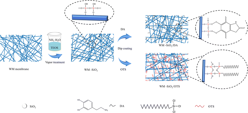
In this work, we propose an effective strategy for recycling waste masks as two inverse wettability membranes for continuous oil/water separation. The micro–nanostructures were successfully constructed by loading homogeneous SiO2 nanoparticles onto the waste masks through in situ chemical deposition, followed by grafting with DA and OTS, respectively (the schematic is shown in Fig. 1). Also, with our self-designed T-shaped device, an oil/water mixture could be continuously separated regardless of the relative density of oil/water. The prepared hydrophilic and hydrophobic membranes modified by the used masks demonstrated a high oil/water flux and separation efficiency. Moreover, the modified membranes displayed good reproducibility and chemical stability and thus show great promise for application in the field of oil/water separation. This method provides a low cost, and environmentally and economically beneficial idea for the disposal of waste masks.
2. Experimental
2.1 Materials
Waste medical surgical masks were collected for use. Ethyl orthosilicate (TEOS), dopamine hydrochloride, carbon tetrachloride (CCl4), OTS, Sudan III, and methyl blue were purchased from Shanghai Maclean Biochemical Co., Ltd. Tris(hydroxymethyl)aminomethane was purchased from Beijing Dingguo Biotechnology Co. Anhydrous ethanol, n-hexane, petroleum ether, cyclohexane, NaClO solution (10%), kerosene, NaOH, Na2SO4, MgSO4, CaCl2, Mg(NO3)2, ammonium hydroxide solution (25 wt%), toluene, hydrochloric acid, and NaCl were purchased from Fuchen (Tianjin) Chemical Reagent Co., Ltd. Soybean oil was purchased from Yihai Kerry Golden Dragonfish Grain, Oil & Food Co., Ltd. Biological sea crystals were purchased from Beijing Red Coral Aquarium Technology Co., Ltd. All the reagents were used without any purification. Deionized water was used throughout all the experiments.2.2 Preparation of the WM-SiO2 membranes
The waste masks were first soaked in 3 g L−1 NaClO solution (obtained by diluting 10 wt% sodium hypochlorite solution), 40 g L−1 NaOH solution, and 75% ethanol for 2 h, respectively. The masks were then dried at 60 °C for 20 min, and then the melt-blown layer (intermediate layer) was obtained and these were marked as the original WM membranes.34 The pristine WM membranes were cut into 10 × 6 cm2 pieces. The original WM membranes were first immersed in TEOS solution for 1 h at room temperature and then centrifuged at 2000 rpm for 3 min to remove excess TEOS. Next, 10 mL NH3·H2O was added to a beaker, and the above masks were placed on top of a spacer and sealed with cling film and subjected to NH3 treatment (and defined as WM-SiO2) at 30 °C for 1 h. After the reaction, the modified membrane was rinsed with deionized water and dried.2.3 Preparation of the WM-SiO2/DA membranes
Different amounts (0, 0.01, 0.05, 0.10, 0.15, 0.20, 0.25 g) of dopamine hydrochloride were sonicated in 100 mL of tris(hydroxymethyl)-aminomethane buffer (pH 8.50), and then the WM-SiO2 membranes were placed in the solution and sonicated for 2 h. Finally, the membranes were cleaned with deionized water and dried at 80 °C for 4 h to obtain WM-SiO2/DA. The membranes modified with DA solutions (0.1, 0.5, 1.0, 1.5, 2.0, 2.5 g L−1) were marked as WM-SiO2/DA-0.1, WM-SiO2/DA-0.5, WM-SiO2/DA-1.0, WM-SiO2/DA-1.5, WM-SiO2/DA-2.0, and WM-SiO2/DA-2.5, respectively.2.4 Preparation of the WM-SiO2/OTS membranes
Different amounts (0, 0.5, 1.0, 1.5, 2.0, 2.5 mL) of OTS were dissolved in toluene solution, and WM-SiO2 membranes were placed under ultrasonic treatment for 2 h. The membranes were then washed with ethanol and deionized water, respectively, and dried at 80 °C for 4 h to obtain WM-SiO2/OTS (OTS was obtained in quantities of 0.5, 1.0, 1.5, 2.0, 2.5 mL and denoted as WM-SiO2/OTS-0.5, WM-SiO2/OTS-1.0, WM-SiO2/OTS-1.5, WM-SiO2/OTS-2.0, and WM-SiO2/OTS-2.5, respectively).2.5 Oil/water separation experiments
![[thin space (1/6-em)]](https://www.rsc.org/images/entities/char_2009.gif) :
:![[thin space (1/6-em)]](https://www.rsc.org/images/entities/char_2009.gif) 1 was poured from the upper glass tube into the assembled separation unit. Under gravity, water/oil passes through the diaphragm and is collected in the conical flask below, while oil/water does not pass through the diaphragm and is intercepted in the tube above. The water/oil flux F (L m−2 h−1) of the modified membrane was calculated by the following equation:
1 was poured from the upper glass tube into the assembled separation unit. Under gravity, water/oil passes through the diaphragm and is collected in the conical flask below, while oil/water does not pass through the diaphragm and is intercepted in the tube above. The water/oil flux F (L m−2 h−1) of the modified membrane was calculated by the following equation: | (1) |
The separation efficiency p (%) of the treated membrane was obtained by the following formula:
 | (2) |
The oil volume before and after oil/water separation was recorded (as V0 and V1, respectively).
The membrane was immersed in ethanol for 10 min and thoroughly washed with deionized water for more than 10 min for the next separation test.
![[thin space (1/6-em)]](https://www.rsc.org/images/entities/char_2009.gif) :
:![[thin space (1/6-em)]](https://www.rsc.org/images/entities/char_2009.gif) 1, v/v) was pumped into the upper tube via a peristaltic pump. The trace oil in the water phase was extracted by CCl4 and then measured by an infrared oil detector. A Karl Fischer moisture meter was used to measure the trace water content in the oil phase. The membrane areas of the two sides were both 9.51 cm2.
1, v/v) was pumped into the upper tube via a peristaltic pump. The trace oil in the water phase was extracted by CCl4 and then measured by an infrared oil detector. A Karl Fischer moisture meter was used to measure the trace water content in the oil phase. The membrane areas of the two sides were both 9.51 cm2.
2.6 Characterization
The morphologies of the original WM, WM-SiO2, WM-SiO2/DA, and WM-SiO2/OTS membranes were observed by scanning electron microscopy (SEM, ZEISS-MERLIN-Compact, Germany). The element mapping of the WM membranes was investigated by energy dispersive spectroscopy (EDS, Verios 460L, USA). The chemical compositions of the original WM, WM-SiO2, WM-SiO2/DA, and WM-SiO2/OTS membranes were examined by attenuated total reflectance Fourier transform infrared (ATR-FTIR, Frontier Mid-IR FTIR/STA6000-TL9000-Clarus SQ8, USA) spectroscopy and X-ray photoelectron spectroscopy (ESCALAB250Xi, UK). A contact angle (CA) measuring machine (SCA20, Germany) was used to record the water contact angle in air (WCA). All the angles were calculated by averaging five parallel measurements made for the different positions of the membrane surface.2.7 Stability testing
The membranes were placed in different salt solutions as well as simulated seawater and different pH solutions for 24 h and then tested for assessing the contact angle and oil–water separation. The simulated seawater was configured from biological sea crystals and deionized water to a 30 g L−1 solution.3. Results and discussion
3.1 Surface characterization
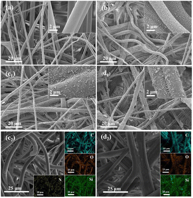
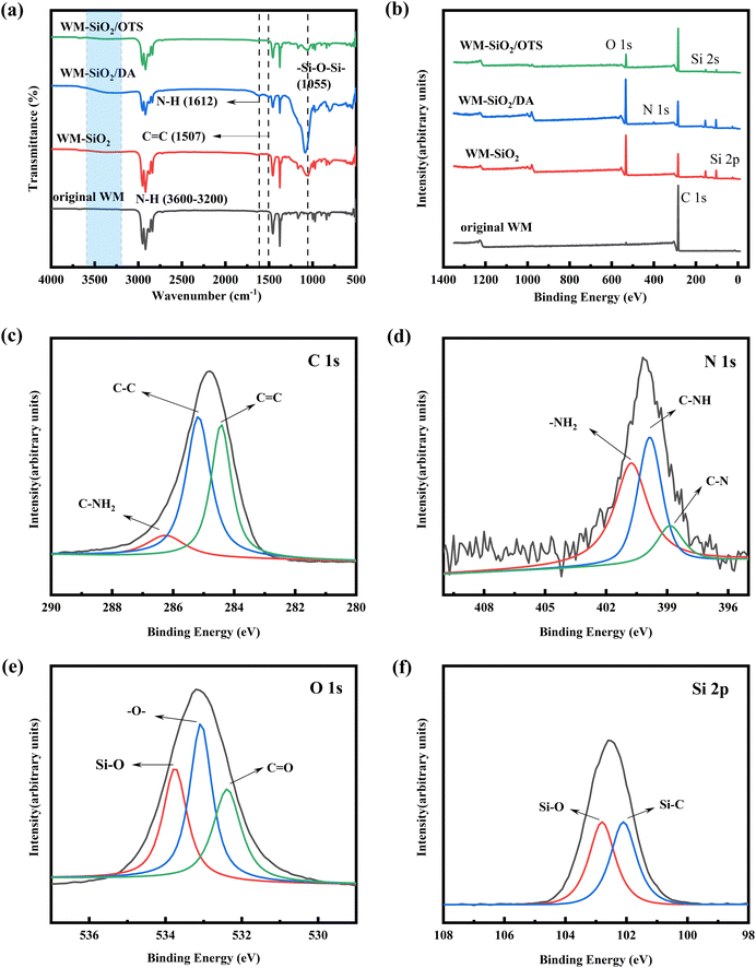
The surface morphologies of the original and modified WM membranes were investigated via SEM, and the results are shown in Fig. 2. The original WM membranes had a three-dimensional (3D) porous structure due to the interlocking arrangement of fibers. The magnified image showed a smooth, clean surface before modification, with an average fiber diameter of approximately 4.3 μm. The uniform distribution of SiO2 nanoparticles on the surface of the WM-SiO2 membranes indicated that the surface of the WM membranes had been successfully modified with SiO2 particles (Fig. 2b). The surface of the membranes became rough after DA and OTS deposition, which showed the successful construction of nanoparticle structures on the WM membranes. DA and OTS connected nanoparticles to each other to form larger particle clusters that adhered to the fiber surface and formed stable rough structures (Fig. 2c and d). To further demonstrate the anchoring and chemical grafting of DA and OTS on the WM membranes, EDS analysis was carried out on the WM-SiO2/DA membranes and WM-SiO2/OTS membranes. The elements N, O, and Si were detected on the surface of the WM-SiO2/DA membranes and O and Si were detected on the surface of the WM-SiO2/OTS membranes. The nanoparticles were uniformly loaded onto the membranes surface by a simple deposition method. These results demonstrated the successful modification.The changes in surface chemical compositions of the pristine and modified WM membranes were monitored using ATR-FTIR and XPS. As shown in Fig. 3a, the ATR-FTIR spectra showed that the WM membranes exhibited several characteristic peaks. The peaks at 2953, 2873, 1377, and 971 cm−1 could be attributed to the asymmetric stretching vibration, symmetric stretching vibration, symmetric deformation vibration, and wobble vibration peak of –CH3, respectively. Besides, the peaks at 2917, 2845, and 1459 cm−1 were the asymmetric stretching vibration peak, symmetric stretching vibration, and bending vibration peak of –CH2–, respectively. The absorption peak of 1055 cm−1 in the WM-SiO2 membranes represented the asymmetric stretching of the Si–O–Si bond, indicating that silica was successfully decorated on the WM membranes' surface. The stretching vibration of the Si–O–Si bond of the WM-SiO2/OTS film appeared at 1055 cm−1, which was due to the combined effect of TEOS and OTS.35,36 Also, the WM-SiO2/DA membranes showed absorption peaks at 3600–3200, 1612, and 1507 cm−1, which were due to the stretching and bending vibrations of N–H bond, and the skeletal vibrations of C![[double bond, length as m-dash]](https://www.rsc.org/images/entities/char_e001.gif) C bond respectively.36,37 The ATR-FTIR results showed the successful loading of nano-SiO2 on the WM membranes' surface and the smooth grafting of DA and OTS.
C bond respectively.36,37 The ATR-FTIR results showed the successful loading of nano-SiO2 on the WM membranes' surface and the smooth grafting of DA and OTS.
Identification of the chemical components in the WM membranes was performed through the XPS spectra. As shown in Fig. 3b, C 1s was detected in the XPS spectra of the original WM membranes at 285 eV. In the WM-SiO2 and WM-SiO2/OTS membranes, peaks for Si 2p, Si 2s, and O 1s appeared at 101.3, 152.3, and 532.5 eV, respectively. Besides, the peak of N 1s in the WM-SiO2/DA membranes occurred at 400 eV, indicating that TEOS and DA were successfully modified on the membranes' surface. To determine the reaction between the nanoparticles, Fig. 3c–f show the XPS analysis of C, N, O elements of WM-SiO2/DA membranes and the Si elements of the WM-SiO2/OTS membranes, respectively. The C 1s peak of the WM-SiO2/DA membranes could be divided into three peaks at 284.6, 285.6, and 286.0 eV, corresponding to the bonds of C![[double bond, length as m-dash]](https://www.rsc.org/images/entities/char_e001.gif) C, C–C, and C–NH2, respectively (Fig. 3c). The O 1s spectrum could be fitted to three peaks at 532.1, 533.0, and 533.3 eV, which were due to the bonds of C
C, C–C, and C–NH2, respectively (Fig. 3c). The O 1s spectrum could be fitted to three peaks at 532.1, 533.0, and 533.3 eV, which were due to the bonds of C![[double bond, length as m-dash]](https://www.rsc.org/images/entities/char_e001.gif) O, –O–, and Si–O, respectively (Fig. 3d). The N 1s peak could be divided into three peaks at 398.1, 399.8, and 400.5 eV, corresponding to the bonds of C–N, C–NH, and –NH2, respectively (Fig. 3e).38 From the above C 1s, N 1s, and O 1s analyses, it could be confirmed that SiO2 and dopamine had a new chemical bonding interaction in the WM-SiO2/DA membranes. The Si 2p peak of the WM-SiO2/OTS membranes could be divided into two peaks at 102.1 and 102.8 eV, corresponding to the Si–C and Si–O bonds, respectively (Fig. 3f).39 The XPS results also demonstrated the successful construction of multilayer nanostructures on the surface of the WM membranes.
O, –O–, and Si–O, respectively (Fig. 3d). The N 1s peak could be divided into three peaks at 398.1, 399.8, and 400.5 eV, corresponding to the bonds of C–N, C–NH, and –NH2, respectively (Fig. 3e).38 From the above C 1s, N 1s, and O 1s analyses, it could be confirmed that SiO2 and dopamine had a new chemical bonding interaction in the WM-SiO2/DA membranes. The Si 2p peak of the WM-SiO2/OTS membranes could be divided into two peaks at 102.1 and 102.8 eV, corresponding to the Si–C and Si–O bonds, respectively (Fig. 3f).39 The XPS results also demonstrated the successful construction of multilayer nanostructures on the surface of the WM membranes.
First, the SiO2 nanoparticles were coated on the WM membranes in order to form a rough structure. The WM was soaked in TEOS solution and treated by NH3 vapor. In this process, numerous Si–OH groups were formed.40 A single fiber was densely and uniformly covered by the SiO2 nanoparticles and the arrangement of SiO2 nanoparticles significantly strongly roughened the WM membranes surface. Also, the TEOS particles could hydrolyze among themselves to form micro/nano-surface roughness, which was beneficial for depositing the DA and OTS on their surface.41 Bioinspired from the adhesive mussel proteins, PDA can adhere to almost all types of inorganic and organic surfaces via the self-polymerization of dopamine under alkaline conditions. During the reaction, the dopamine was oxidized to dopamine quinone, and then the formed dopamine quinone continued to react with other quinones and catechols to afford PDA.42 Furthermore, PDA continued to be formed around the SiO2 nanoparticles under the alkaline aqueous condition, and thereby SiO2-based micro-/nanostructures could be continuously enhanced during the self-polymerization of dopamine. The WM membranes coated by SiO2 nanoparticles were modified by the OTS reagent, and the wetting behavior of this surface showed a great improvement. By this OTS treatment, the hydroxyl groups produced from OTS hydrolysis reacted with the hydroxyl groups of SiO2 nanoparticles, and thus long-chain hydrophobic alkyls were introduced on the WM membranes surface.
3.2 Waste mask membrane wettability
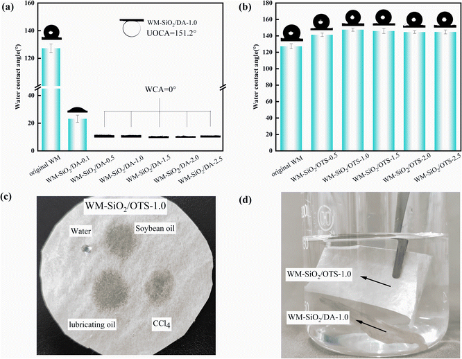
The hydrophilicity/hydrophobicity of the membrane surface has a large impact on the oil–water separation performance. The surface groups have an important influence on the hydrophilicity and hydrophobicity of the material. DA is rich in amino and hydroxyl groups, so it is often used as a surface hydrophilic modification material,43–45 while OTS contains a long alkane chain and is a good hydrophobic modification material.46,47 As shown in Fig. 4, the original WM membranes showed hydrophobic properties with a WCA of 125°. This indicated that the WM membrane itself was somewhat hydrophobic, due to the alkyl groups in the polypropylene molecule. All the WM-SiO2/DA membranes showed superhydrophilic properties with WCAs of 0°. Besides, the WM-SiO2/DA membranes had a contact angle of 151.2° for submerged oil (hexane). The contact angle of the WM-SiO2/OTS membranes first increased and then stabilized with the increase in the mass of OTS, whereby the maximum contact angles was 147.5° for OTS ∼ 1.0 g (WM-SiO2/OTS-1.0). The significant increase in hydrophobicity of the OTS-modified membranes could be attributed to the successful introduction of hydrophobic chemicals and the construction of hierarchical nanostructures.48 The selective wettability of the WM-SiO2/OTS-1.0 membrane was further verified by placing different droplets on the surface of the WM-SiO2/OTS-1.0 membranes (Fig. 4c). In addition, a transparent ‘mirror image’ phenomenon was observed below the water surface when WM-SiO2/DA-1.0 and WM-SiO2/OTS-1.0 membranes were immersed in water, indicating the non-wetting state of the WM-SiO2/OTS-1.0 membranes. The hydrophobicity and the presence of air bubbles at the interface caused the WM-SiO2/OTS-1.0 membranes to float on the water surface while the WM-SiO2/DA-1.0 membranes sank into the water (Fig. 4d). The improved hydrophilicity/hydrophobicity gave the WM membranes excellent oil/water separation properties. Therefore, the hydrophilic and hydrophobic properties of the WM membranes suggest their potential as oil/water separation membranes.3.3 Oil/water separation performance
The separation process is shown in Fig. S1 and S2† and was used to verify the effectiveness of the membrane for separating oil and water. The oil/water mixture (v/v = 1![[thin space (1/6-em)]](https://www.rsc.org/images/entities/char_2009.gif) :
:![[thin space (1/6-em)]](https://www.rsc.org/images/entities/char_2009.gif) 1) was poured into a filter separator for oil/water separation with the WM-SiO2/DA-1.0 and WM-SiO2/OTS-1.0 membranes. The deionized water (dyed blue) quickly permeated through the WM-SiO2/DA-1.0 under gravity and was collected in the conical flask, while CCl4 (dyed green) and soybean oil (dyed red) were trapped in the upper tube and failed to pass through the membrane. In contrast, CCl4 rapidly permeated through the WM-SiO2/OTS-1.0 membrane and was collected in the beaker, while deionized water was trapped in the upper tube and failed to pass through the membrane.
1) was poured into a filter separator for oil/water separation with the WM-SiO2/DA-1.0 and WM-SiO2/OTS-1.0 membranes. The deionized water (dyed blue) quickly permeated through the WM-SiO2/DA-1.0 under gravity and was collected in the conical flask, while CCl4 (dyed green) and soybean oil (dyed red) were trapped in the upper tube and failed to pass through the membrane. In contrast, CCl4 rapidly permeated through the WM-SiO2/OTS-1.0 membrane and was collected in the beaker, while deionized water was trapped in the upper tube and failed to pass through the membrane.
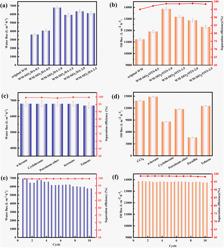
As shown in Fig. 5a–d, in oil–water separation experiments, the WM-SiO2/DA and WM-SiO2/OTS membranes were separated using a mixture of deionized water and n-hexane/CCl4, respectively. The fluxes of both the WM-SiO2/DA and WM-SiO2/OTS membranes tended to increase and then decreased with the increase in DA/OTS addition. The WM membranes were unable to pass water due to their hydrophobicity. The WM-SiO2/DA-1.0 membrane had the highest flux of 6953 L m−2 h−1 for deionized water, with an oil–water separation efficiency of 98.65%. The WM-SiO2/OTS-1.0 membrane showed the highest flux of 13![[thin space (1/6-em)]](https://www.rsc.org/images/entities/char_2009.gif) 867 L m−2 h−1 for CCl4, with an oil/water separation efficiency of 98.65%. The decrease in flux was due to the increase in DA/OTS, causing the nanoparticles on the membrane surface to join into flakes and clump together, blocking the effective pores on the membrane surface (Fig. S3†), and thus leading to a decrease in the flux. The change in pore size before and after OTS modification is shown in Fig. S4,† in which the WM membrane exhibited a pore size range of 16–17 μm, while the WM-SiO2/OTS-1.0 membrane had a pore size range of 10–13 μm.
867 L m−2 h−1 for CCl4, with an oil/water separation efficiency of 98.65%. The decrease in flux was due to the increase in DA/OTS, causing the nanoparticles on the membrane surface to join into flakes and clump together, blocking the effective pores on the membrane surface (Fig. S3†), and thus leading to a decrease in the flux. The change in pore size before and after OTS modification is shown in Fig. S4,† in which the WM membrane exhibited a pore size range of 16–17 μm, while the WM-SiO2/OTS-1.0 membrane had a pore size range of 10–13 μm.
The separation effect of the WM-SiO2/DA-1.0 membranes on different kinds of oil/water mixtures was investigated; for example, n-hexane, cyclohexane, petroleum ether, kerosene, and ethyl acetate. The oil/water volume ratio was 1![[thin space (1/6-em)]](https://www.rsc.org/images/entities/char_2009.gif) :
:![[thin space (1/6-em)]](https://www.rsc.org/images/entities/char_2009.gif) 1. Fig. 5c displayed that the membrane separation efficiencies for the five oil/water mixtures tested were all higher than 99.0%. Meanwhile, the maximum water flux was about 6796 L m−2 h−1. The fluxes of the WM-SiO2/OTS-1.0 membranes were also investigated for different types of oils; for example, CCl4, n-hexane, cyclohexane, petroleum ether, paraffin, and toluene. Fig. 5d shows that n-hexane had the highest flux with 14
1. Fig. 5c displayed that the membrane separation efficiencies for the five oil/water mixtures tested were all higher than 99.0%. Meanwhile, the maximum water flux was about 6796 L m−2 h−1. The fluxes of the WM-SiO2/OTS-1.0 membranes were also investigated for different types of oils; for example, CCl4, n-hexane, cyclohexane, petroleum ether, paraffin, and toluene. Fig. 5d shows that n-hexane had the highest flux with 14![[thin space (1/6-em)]](https://www.rsc.org/images/entities/char_2009.gif) 895 L m−2 h−1.
895 L m−2 h−1.
The n-hexane/water mixture was used to evaluate the reusability and restorability of the WM-SiO2/DA-1.0 membranes. Each modified membrane was used for 10 consecutive oil/water separation processes. As shown in Fig. 5e, the WM-SiO2/DA-1.0 membranes still maintained a high flux (above 5600 L m−2 h−1) and separation efficiency (above 99.5%) even after 10 oil/water separation cycles, manifesting the modified WM-SiO2/DA-1.0 membranes possessed favorable reusability. The WM-SiO2/OTS-1.0 membranes were subjected to 10 consecutive oil–water/CCl4 mixture separation processes. As shown in Fig. 5f, the WM-SiO2/OTS-1.0 membrane maintained a high flux (13![[thin space (1/6-em)]](https://www.rsc.org/images/entities/char_2009.gif) 690 L m−2 h−1) and separation efficiency (above 98.0%) after 10 oil/water separation cycles, indicating that the WM-SiO2/OTS-1.0 membrane exhibited a good self-cleaning property and reusability. However, we also observed that the flux showed a gradual decrease as the cycling experiment progressed, which could be due to oil contamination and pore blockage.
690 L m−2 h−1) and separation efficiency (above 98.0%) after 10 oil/water separation cycles, indicating that the WM-SiO2/OTS-1.0 membrane exhibited a good self-cleaning property and reusability. However, we also observed that the flux showed a gradual decrease as the cycling experiment progressed, which could be due to oil contamination and pore blockage.
3.4 Stabilities of the waste mask membranes
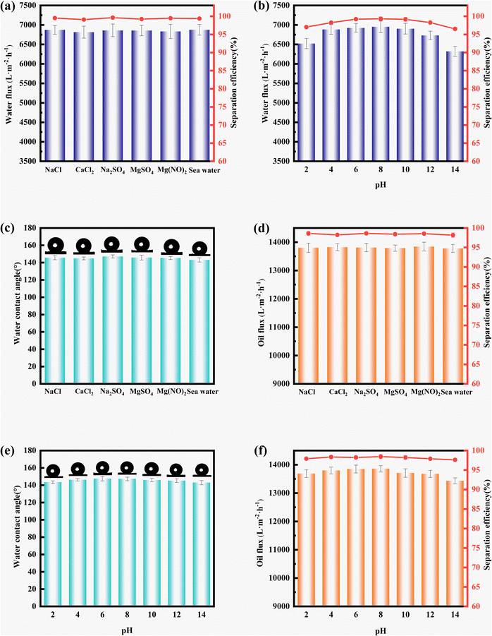
Considering that nanostructures are subject to damage from various harsh environments in practical applications, the stability of the membranes is more of an advantage. We demonstrated the membrane stability by measuring the WCA and oil/water separation performance after immersion in salt and acid–base solutions. As shown in Fig. 6a, the WM-SiO2/DA-1.0 membranes were placed in aqueous solutions of various inorganic salts at a concentration of 1 mol L−1 for 24 h, respectively. The inorganic salts included MgSO4, Na2SO4, CaCl2, NaCl, Mg(NO3)2, and simulated seawater. In addition, the membranes were immersed in acid–base solutions for 24 h. There was no significant difference in the water flux and oil–water separation efficiency of the WM-SiO2/DA-1.0 membranes after immersion in the salt solution. As shown in Fig. 6b, the WM-SiO2/DA-1.0 membranes remained stable at pH values of 2–12, with no significant decrease in the flux (above 6730 L m−2 h−1) or separation efficiency (above 97%). At pH values less than 2 and greater than 12, the hydrophilicity of the membranes decreased, resulting in a lower flux and separation efficiency.Similarly, the WM-SiO2/OTS-1.0 membranes remained highly hydrophobic after immersion in the salt solution, with all the contact angles remaining above 143.1° and no significant changes in the flux or separation efficiency (Fig. 6c and d). The results indicate that immersion in salt solutions did not make a significant difference. In addition, the membranes remained highly hydrophobic after immersion in different pH solutions, with a stable contact angle of over 142.9° and no significant reduction in the flux or separation efficiency (Fig. 6e and f). These results indicate that it was difficult for the salt solution to damage the chemical structure of the modified membrane surface. In strong acid and alkali environments, hydroxyl groups were negatively charged due to deprotonation, which greatly enhanced the electrostatic repulsion in the modified structure. As a result, the modified layer was slightly damaged, resulting in a decrease in the flux and separation efficiency. In addition, it can be seen from Fig. S5† that the nanoparticles remained stable on the membrane surface under the different conditions. The above findings indicate that the WM-SiO2/OTS-1.0 and WM-SiO2/DA-1.0 membranes had good salt tolerance and chemical stability.
3.5 Continuous oil–water separation performances of the membranes
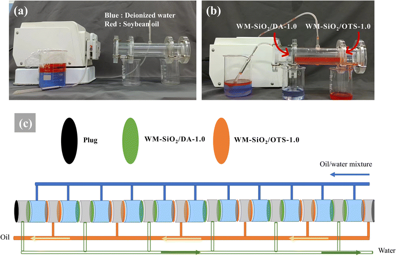
In this study, we designed a T-shaped device (total length 20 cm, diameter 3 cm), as shown in Fig. 7a, for continuous oil–water separation. When the oil/water mixture flowed into the T-shaped device driven by a peristaltic pump, there was no need to consider the oil/water density relationship. The oil phase flowed from the hydrophobic WM-SiO2/OTS-1.0 membrane (right side) and the water phase flowed from the hydrophilic WM-SiO2/DA-1.0 membrane (left side). The separation unit could achieve a feeding flux of more than 2000 L m−2 h−1 with a separation efficiency higher than 95.0%. Furthermore, it is expected that a single unit could process at least 2.0 m3 of mixed oil–water solution per hour. With the large T-shaped unit (Fig. 7c), the efficient separation of large water areas is possible. This also demonstrates the feasibility of practical oil/water separation and solves the constraints of membrane separation due to the different oil/water densities (captured from Movie S1†).3.6 Oil/water separation mechanism
Eqn (3) can be used to explain the invasion process of oil and water: | (3) |
According to eqn (3), when the liquid contact angle θ < 90°, ΔP < 0, the membrane has no resistance to the liquid, and the liquid can permeate through the membrane spontaneously, whereas when the liquid contact angle θ > 90°, ΔP > 0, the membrane is resistant to fluid and requires pressure for the fluid to penetrate the membrane. For the WM-SiO2/OTS membranes prepared in this work, due to the preparation of the membrane with an oil wetting angle of θ < 90°, oil can permeate through the membrane spontaneously; however, the membrane had great resistance to water (θ > 90°). In addition, in the process of oil–water separation, oil will first penetrate through the membrane and leave oil in the membrane, while the repulsive nature of oil and water further makes it difficult for water to enter, and ultimately prevents water from permeating through the membrane during gravity separation. Similarly, the WM-SiO2/DA membrane prevents the passage of oil.
4. Conclusions
In this study, SiO2 nanoparticles were uniformly loaded onto the waste masks by in situ chemical deposition. Two modified WM membranes with anti-infiltration properties were obtained by grafting DA and OTS. The water contact angles of the hydrophilic/hydrophobic membranes were 0° (WM-SiO2/DA-1.0) and 147.5° (WM-SiO2/OTS-1.0), respectively. The modified membranes were able to achieve the efficient separation of different oil–water mixtures under gravity, with a maximum water flux of 6793 L m−2 h−1 (water) for the hydrophilic membranes and 13![[thin space (1/6-em)]](https://www.rsc.org/images/entities/char_2009.gif) 867 L m−2 h−1 (CCl4) for the hydrophobic membranes, and no significant decrease in flux or separation efficiency for 10 consecutive separation tests. Furthermore, the membranes also displayed favorable stability and reusability under harsh operating conditions. By using the self-designed T-shaped device, oil/water mixtures could be continuously separated regardless of the relative density of oil/water. The modified membrane shows great promise for oil/water separation and provides a low carbon, environmentally friendly technical means for the disposal of waste masks.
867 L m−2 h−1 (CCl4) for the hydrophobic membranes, and no significant decrease in flux or separation efficiency for 10 consecutive separation tests. Furthermore, the membranes also displayed favorable stability and reusability under harsh operating conditions. By using the self-designed T-shaped device, oil/water mixtures could be continuously separated regardless of the relative density of oil/water. The modified membrane shows great promise for oil/water separation and provides a low carbon, environmentally friendly technical means for the disposal of waste masks.
Conflicts of interest
There are no conflicts to declare.Acknowledgements
We gratefully acknowledge financial support from Tianjin Enterprise Science and Technology Commissioner Project (18JCTPJC48600), Tianjin Natural Science Foundation (16JCYBJC19400) and Tianjin “Project + Team” Key Training Special Project (XC202047).References
- H. Du, F. Liu and H. Wang, J. Colloid Interface Sci., 2022, 616, 720–729 CrossRef CAS PubMed.
- F. Aghili, A. A. Ghoreyshi, B. Van der Bruggen and A. Rahimpour, Process Saf. Environ. Prot., 2021, 151, 244–256 CrossRef CAS.
- P. S. Dhumal, R. V. Khose, P. H. Wadekar, K. D. Lokhande and S. Some, Sep. Purif. Technol., 2021, 266, 118569 CrossRef CAS.
- Y. Wang, X. Yu, W. Fan, R. Liu and Y. Liu, Carbohydr. Polym., 2022, 294, 119755 CrossRef CAS PubMed.
- M. Đorđević, Đ. Šabalja, Đ. Mohović and D. Brčić, J. Mar. Sci. Eng., 2022, 10, 925 CrossRef.
- P. H. Hoang, H. T. Dat, T. D. Cuong and L. Q. Dien, RSC Adv., 2022, 12, 14976–14985 RSC.
- L. Wei, M. Li, F. Gao, Y. Zhang, C. Li and Q. Zhang, J. Water Process. Eng., 2022, 48, 102852 CrossRef.
- A. Gila, M. P. Aguilera, A. Sánchez-Ortíz, A. Jiménez and G. Beltrán, J. Food Eng., 2022, 334, 111169 CrossRef CAS.
- C. Haddaji, K. Ennaciri, A. Driouich, K. Digua and S. Souabi, Process Saf. Environ. Prot., 2022, 160, 803–816 CrossRef CAS.
- Y. Davarikia, A. Aroujalian and P. Salimi, Process Saf. Environ. Prot., 2022, 166, 656–668 CrossRef CAS.
- D. Ji, Y. Gao, W. Wang, H. Feng, K. Chen and C. Xiao, J. Environ. Chem. Eng., 2022, 10, 108337 CrossRef CAS.
- X. Sun, X. Wang, J. Li, L. Huang, H. Sun, Y. Hao, L. Bai, J. Pan and X. Gao, Sep. Purif. Technol., 2022, 287, 120617 CrossRef CAS.
- X.-T. He, B.-Y. Li, J.-X. Liu, W.-Q. Tao and Z. Li, Sep. Purif. Technol., 2022, 297, 121488 CrossRef CAS.
- G. Akhlamadi and E. K. Goharshadi, Process Saf. Environ. Prot., 2021, 154, 155–167 CrossRef CAS.
- T. J. Mpala, A. Etale, H. Richards and L. N. Nthunya, Environmental Science: Advances, 2023, 2, 39–54 Search PubMed.
- N. Barati, M. M. Husein and J. Azaiez, Environ. Sci.: Water Res. Technol., 2022, 8, 2856–2872 RSC.
- B. Xiang, Q. Sun, Q. Zhong, P. Mu and J. Li, J. Mater. Chem. A, 2022, 10, 20190–20217 RSC.
- Q. Zhong, G. Shi, Q. Sun, P. Mu and J. Li, J. Membr. Sci., 2021, 640, 119836 CrossRef CAS.
- M. Wu, B. Xiang, P. Mu and J. Li, Sep. Purif. Technol., 2022, 297, 121532 CrossRef CAS.
- A. Said, H. Al Abdulgader, D. Alsaeed, Q. A. Drmosh, T. N. Baroud and T. A. Saleh, J. Water Process. Eng., 2022, 49, 102931 CrossRef.
- S. H. Tabatabaei, P. J. Carreau and A. Ajji, J. Membr. Sci., 2008, 325, 772–782 CrossRef CAS.
- P. B. Kosaraju and K. K. Sirkar, J. Membr. Sci., 2008, 321, 155–161 CrossRef CAS.
- X. Q. Cheng, Y. L. Zhang, Z. X. Wang, Z. H. Guo, Y. P. Bai and L. Shao, Adv. Polym. Technol., 2014, 33, 21455 CrossRef.
- F. Sun, T.-T. Li, X. Zhang, B.-C. Shiu, Y. Zhang, H.-T. Ren, H.-K. Peng, J.-H. Lin and C.-W. Lou, Chemosphere, 2020, 254, 126873 CrossRef CAS PubMed.
- C. Li, L. Ren, C. Zhang, W. Xu and X. Liu, Adv. Fiber Mater., 2021, 3, 138–146 CrossRef CAS.
- C. Gogoi, A. Rana, S. Ghosh, R. Fopase, L. M. Pandey and S. Biswas, ACS Appl. Nano Mater., 2022, 5, 10003–10014 CrossRef CAS.
- M. R. Cordova, I. S. Nurhati, E. Riani, Nurhasanah and M. Y. Iswari, Chemosphere, 2021, 268, 129360 CrossRef CAS PubMed.
- J. C. Prata, A. L. P. Silva, T. R. Walker, A. C. Duarte and T. Rocha-Santos, Environ. Sci. Technol., 2020, 54, 7760–7765 CrossRef CAS PubMed.
- D. Hantoko, X. Li, A. Pariatamby, K. Yoshikawa, M. Horttanainen and M. Yan, J. Environ. Manage., 2021, 286, 112140 CrossRef CAS PubMed.
- H. Zhang, J. Liu, X. Zhang, C. Huang and X. Jin, J. Appl. Polym. Sci., 2018, 135, 45948 CrossRef.
- L. Castillo, L. Lescano, S. Marfil and S. Barbosa, Polym. Eng. Sci., 2022, 62, 2476–2485 CrossRef CAS.
- L. Ning, Y. Han, Q. Li, Z. Liu and M. Zhang, Environ. Eng., 2022, 1–12 Search PubMed.
- S. Park, Y. Kim, W. Lee and C. Nam, Chemosphere, 2022, 303, 135186 CrossRef CAS PubMed.
- O. Guselnikova, O. Semyonov, M. Kirgina, A. Ivanov, A. Zinoviev and P. Postnikov, J. Environ. Chem. Eng., 2022, 10, 107105 CrossRef CAS.
- M. Xia, T. Yang, S. Chen and G. Yuan, Colloid Interface Sci. Commun., 2020, 36, 100264 CrossRef CAS.
- L. Liu, W. Fu, L. Wang and X. Shan, New J. Chem., 2021, 45, 11544–11551 RSC.
- F. Sun, T.-T. Li, H.-T. Ren, B.-C. Shiu, H.-K. Peng, J.-H. Lin and C.-W. Lou, Process Saf. Environ. Prot., 2021, 147, 788–797 CrossRef CAS.
- M. Wang, X. Cheng, G. Jiang, J. Xie, W. Cai, J. Li and Y. Wang, J. Membr. Sci., 2022, 653, 120535 CrossRef CAS.
- M. H. Tai, B. C. Mohan, Z. Yao and C.-H. Wang, Chemosphere, 2022, 286, 131520 CrossRef CAS PubMed.
- Z. Liu, Z. Qin, G. Zhao, J. T. Aladejana, H. Wang, A. Huang, D. Chen, Y. Xie, X. Peng and T. Chen, Compos. Commun., 2021, 25, 100763 CrossRef.
- Y. Gao, Y. S. Zhou, W. Xiong, M. Wang, L. Fan, H. Rabiee-Golgir, L. Jiang, W. Hou, X. Huang, L. Jiang, J.-F. Silvain and Y. F. Lu, ACS Appl. Mater. Interfaces, 2014, 6, 5924–5929 CrossRef CAS PubMed.
- Z. He, H. Wu, Z. Shi, X. Gao, Y. Sun and X. Liu, Langmuir, 2022, 38, 6086–6098 CrossRef CAS PubMed.
- H.-M. Song, L.-J. Zhu, W.-H. Zhang, G. Wang, Z.-X. Zeng and B.-K. Zhu, Appl. Surf. Sci., 2022, 589, 152973 CrossRef CAS.
- S. Muchtar, M. Y. Wahab, S. Mulyati, N. Arahman and M. Riza, J. Water Process. Eng., 2019, 28, 293–299 CrossRef.
- Z. Liu, Z. Xu, C. Liu, Y. Zhao, Q. Xia, M. Fang, X. Min, Z. Huang, Y. Liu and X. Wu, Molecules, 2021, 26, 3258 CrossRef CAS PubMed.
- Y. Chenxi, W. Jian, Z. Haiou, C. Tingting, Z. Hang, W. Jiawei and B. Bo, Sci. Rep., 2022, 12, 7632 CrossRef PubMed.
- S. Qing, H. Chen, Z. Ye and L. Han, Microporous Mesoporous Mater., 2022, 335, 111852 CrossRef CAS.
- W. Qing, X. Li, Y. Wu, S. Shao, H. Guo, Z. Yao, Y. Chen, W. Zhang and C. Y. Tang, J. Membr. Sci., 2020, 612, 118476 CrossRef CAS.
Footnote |
| † Electronic supplementary information (ESI) available. See DOI: https://doi.org/10.1039/d2va00295g |
| This journal is © The Royal Society of Chemistry 2023 |

