 Open Access Article
Creative Commons Attribution 3.0 Unported Licence
White-light emitting multi-lanthanide terephthalate thin films by atomic/molecular layer deposition†
Amr
Ghazy
 a,
Mika
Lastusaari
 b and
Maarit
Karppinen
 *a
*a
aDepartment of Chemistry and Materials Science, Aalto University, FI-00076, Espoo, Finland. E-mail: maarit.karppinen@aalto.fi
bDepartment of Chemistry, University of Turku, FI-20014, Turku, Finland
First published on 29th March 2023
Abstract
Precisely composition-tuned white-light-emissive lanthanide-organic thin films are fabricated using the combined atomic/molecular layer deposition (ALD/MLD) technique. The emission colour characteristics are comparable (and even exceeding) to those measured for commercial incandescent bulbs, fluorescent tubes and LED lamps. The films are composed of up to four lanthanide species (La, Er, Tb, and Eu) and terephthalate as the organic linker molecule. Terephthalate plays multiple roles in the films, as it not only brings mechanical flexibility to the films and defines the distance between the lanthanide ions, but also shows upon UV excitation UV/blue broad-band emission around 300–450 nm. This excitation energy was found to be efficiently transferred to the Er3+ ions, such that the emission could be shifted to the longer wavelengths. Then, Tb and Eu provide the green and red emissions, such that the films in overall show warm white light emission. Finally, using a three-layer composition to control the distribution of the Ln dopants, the emission intensity was increased fourfold.
1 Introduction
White-light emitting materials are increasingly demanded for applications ranging from light-emitting diodes (LEDs) and backlight sources of displays to solar concentrators, biomedical imaging and photodynamic therapy.1,2 Organic light-emitting diodes (OLEDs) generate white light and are currently used in displays. However, these wide-band materials usually show weak emission intensity and poor colour purity and lack long-term stability.3,4Trivalent lanthanide (Ln) ions with their parity-forbidden f–f transitions are the most widely employed components of coloured LEDs.5 The spatially extended 5s and 5p orbitals of the Ln3+ ions offer shielding to the 4f electrons, which makes the emission wavelengths independent of the host lattice or the ligand environment. On the other hand, lanthanides like Ce3+ and Eu2+ whose emission is due to a transition from the 5d to 4f orbitals show emission in different colours depending on the host material. The lanthanide-based f–f emitting luminescent materials show narrow emission bands, long luminescence lifetimes (μs to ms),6 high colour purity, and a high colour rendering index. Based on these characteristics, Ln3+ ions are highly prominent constituents for white-light emitting materials as well, when applied in appropriate mixtures.7
A straightforward strategy to generate white light through lanthanide-based photoluminescence is to mix different Ln3+ ions exhibiting characteristic emissions in red, green, and blue wavelengths.1 Trivalent europium is well known for its strong red emission with the strongest emission peaks located around 620 and 700 nm, while Tb3+ shows an intense green emission around 545 nm and also a weak blue emission at 490 nm.8 Hence, these two Ln3+ species have been combined with a blue emitting lanthanide such as Ce3+, Eu2+, Dy3+, and Tm3+.9–11 Blue emitters can also be used in combination with yellow or orange colour emitters such as Ce3+ or Sm3+.12
A common issue with lanthanide luminescence is the so-called concentration quenching phenomenon,13 seen when the emitting Ln3+ ions are spatially too closely packed. To overcome this issue, the luminescent Ln3+ ions are typically applied as dopants in relatively small concentrations embedded within a suitable host lattice.14 Various oxides, nitrides, fluorides, and ceramics such as borates,15,16 germanates,17 and zirconates18 have been actively investigated as possible host lattices.
Another issue with the lanthanides is their notoriously low absorption cross-sections. Here, a possible solution could be to combine the visible-light emitting Ln3+ ions with organic species known as potential UV-light absorbers. Both Ln-based metal organic complexes and metal organic framework (MOF) materials have been investigated.19–21 The organic linkers in these materials may play a dual role, as they could show visible range emission on their own and also simultaneously act as sensitizers for the lanthanide emission through a so-called antenna effect. In the latter case, the energy absorbed by the organic moiety generates an excited state photon that undergoes an energy transfer to the Ln3+ ion which then emits its characteristic luminescence.22 Also importantly, Ln-organic complexes are often both chemically and thermally stable.23
Traditionally, the Ln-organic materials are synthesized through solvothermal or sol–gel routes in bulk form. However, most of the target applications (e.g. displays) require the white-light emitting materials in high-quality thin-film form, and the apparent challenge is that the so far most widely employed solution-based spin-coating and dip-coating techniques are not compatible with the current microelectronics technologies, as they tend to leave solvent traces in the thin films; moreover, these techniques lack the precise control of the film thickness, homogeneity and conformality.24
Atomic layer deposition (ALD) is the state-of-the-art gas-phase thin-film fabrication technology widely adopted in the microelectronics industry for applications related e.g. to transistors and displays.25 In ALD, different gaseous/vaporized metal and co-reactant precursors are sequentially pulsed into the reactor chamber, each precursor pulse followed by an inert gas purging step to remove the excess precursor molecules after the desired surface reactions have occurred. Thanks to the self-limiting nature of these chemical surface reactions, ALD offers pinhole-free and highly uniform and conformal thin films with atomic-level thickness control. The counterpart of ALD for organic thin films was developed more recently; this method is called molecular layer deposition (MLD).26 In MLD purely organic gaseous/vaporized precursors are employed. Most importantly, both ALD and MLD are modular, meaning that for the deposition of high-quality metal–organic thin films ALD and MLD precursor pulses can be combined.27,28 This currently strongly emerging hybrid ALD/MLD technique has already been employed for the fabrication of tens of novel metal–organic thin-film materials showing intriguing functional properties well beyond those realized for purely inorganic or organic thin films.29 For example, mechanical properties of the ALD/MLD-grown metal–organic thin films are often several orders of magnitude better than those of ALD-grown inorganic thin films, which is important e.g. in flexible electronics applications.30,31
Conventional ALD has been applied for inorganic lanthanide-based thin films since the 1990s.32,33 Also, there are already several successful ALD/MLD processes reported for various Ln-organic materials with intriguing photoluminescence and upconversion properties.34–37 Moreover, these processes are compatible with a wide range of substrates including flexible ones.38 In this paper, we demonstrate for the first time the fabrication of white-light emitting Ln-organic thin films through ALD/MLD. Our ALD/MLD process allows the combination of multiple lanthanides (Eu, Tb, Er and La) together with terephthalic acid (TPA) as the organic component. Most importantly, we discuss the roles of each of these components, the different lanthanides and the terephthalate moiety, in the white light generation.
2 Experimental section
The lanthanide-terephthalate thin films were deposited using appropriate combinations of in-house synthesized La(thd)3, Er(thd)3, Eu(thd)3, and Tb(thd)3 (thd = 2,2,6,6-tetramethyl-3,5-heptanedione) powders as the metal precursors. Terephthalic acid (TPA; 1,4-benzenedicarboxylic acid; Tokyo Chemical Industry Co., Ltd) was used as the organic precursor. All these precursor powders were kept in open crucibles inside the reactor. As in our reactor setup, there are only four crucibles, we mixed the Eu(thd)3 and Tb(thd)3 precursor powders into a single powder (Tb,Eu)(thd)3 at a molar Eu![[thin space (1/6-em)]](https://www.rsc.org/images/entities/char_2009.gif) :
:![[thin space (1/6-em)]](https://www.rsc.org/images/entities/char_2009.gif) Tb ratio of 3
Tb ratio of 3![[thin space (1/6-em)]](https://www.rsc.org/images/entities/char_2009.gif) :
:![[thin space (1/6-em)]](https://www.rsc.org/images/entities/char_2009.gif) 10 for the depositions involving all the four metal constituents (La, Er, Tb and Eu). The precursor powders were heated to the following temperatures for the effective sublimation: La(thd)3 at 170 °C, Tb(thd)3 and Eu(thd)3 and their mixture at 140 °C, Er(thd)3 at 120 °C, and TPA at 185 °C.
10 for the depositions involving all the four metal constituents (La, Er, Tb and Eu). The precursor powders were heated to the following temperatures for the effective sublimation: La(thd)3 at 170 °C, Tb(thd)3 and Eu(thd)3 and their mixture at 140 °C, Er(thd)3 at 120 °C, and TPA at 185 °C.
A common way to deposit multi-metal films in the combined ALD/MLD (like in conventional ALD) is to use a so-called super-cycle concept; the super-cycle consists of the different individual metal precursor plus co-reactant (here: TPA) cycles, which are applied according to a predetermined sequence to achieve the desired metal composition in the resultant thin film. In this work, we first of all fixed the total number of individual ALD/MLD cycles to 200, to achieve thin films of ca. 63 nm in thickness. The super-cycle sequences were then designed (for most of the experiments) so as to achieve as homogeneous mixing of the different metal components as possible. For example, for our sample named La70-Er10-Tb15-Eu5, the super-cycle consisted of the following metal precursor pulses: 19 × [7 × La(thd)3 + 2 × (Tb,Eu)(thd)3 + 1 × Er(thd)3] + [7 × La(thd)3 + (Tb,Eu)(thd)3 + 2 × Er(thd)3]; each metal precursor pulse was naturally followed by a TPA pulse. Additionally, we fabricated one multilayer sample, called La70-Er10-Tb15-Eu5-ML, as follows: first layer: 101 × La(thd)3; second layer: 21 × [La(thd)3 + Er(thd)3 + (Tb,Eu)(thd)3]; third layer: 18 × [La(thd)3 + (Tb,Eu)(thd)3].
All the depositions were carried out in the same commercial flow-type hot-wall ALD reactor (F-120 by ASM Microchemistry Ltd). During the depositions, the reactor pressure was maintained between 2–4 mbar and nitrogen (>99.999%; Schmidlin UHPN 3000 N2 generator) was used both as the purging and carrier gas. The samples were deposited on Si(100) substrates cut into 20 × 20 mm2 size. The precursor pulse/N2 purge lengths were adopted from our previous studies involving these precursors.34,36,39 For all the Ln(thd)3 precursors, the pulse length was 3 s followed by a 4 s N2 purge, while for TPA, the pulse length was 7 s and the purge length was 15 s. After initial tests, all the final thin-film depositions were carried out at the substrate temperature of 190 °C.
The thickness, density and surface roughness were determined for each thin-film sample studied using X-ray reflectivity (XRR; X’Pert Pro MPD, PANalytical; Cu Kα), while the analysis is done using the X’Pert. All the films were amorphous (as expected) but the chemical bonding mode between the Ln and TPA species was investigated using Fourier transform infrared (FTIR) spectroscopy. The measurements were carried out in a transmission mode using a Bruker Alpha II FTIR spectrometer in the range of 500–4000 cm−1.
Photoluminescence measurements were carried out at room temperature using an Edinburgh Instruments FLS1000 spectrometer with a continuous wave 450 W Xe lamp (Xe2) as the excitation source and a PMT-900 photomultiplier tube as the detector. The emission spectra presented here were recorded using 250 nm as the excitation wavelength. The CIE1931 colour coordinates, colour correlated temperature and colour rendering index were calculated using the Osram Sylvania LED ColorCalculator software.
3 Results and discussion
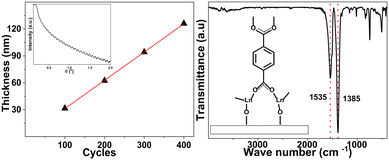
As expected from our previous works on various related single-lanthanide ALD/MLD processes, the present depositions yielded high-quality (smooth and visually homogeneous) amorphous lanthanide-organic thin films with excellent control of the film thickness. Fig. 1(a) shows the linear (R2 = 0.999) dependency of the film thickness on the number of ALD/MLD cycles applied for the La-terephthalate (La100) films; a representative XRR pattern revealing the clear fringes as an indication of the film smoothness is shown in the inset. The growth-per-cycle (GPC) value calculated from the film thickness values, i.e. 3.1 Å per cycle, matches well with our previous results, see the ESI.†35,36 Furthermore, the FTIR spectrum shown in Fig. 1(b) confirms the expected La-terephthalate bond formation, and the absence of unreacted carboxylic acid moieties (peaks of which would appear around 1700 cm−1). Most importantly, the FTIR spectrum provides us information of the bonding mode between the Ln ions and terephthalate moiety: from the separation between the symmetric and asymmetric stretching vibrations of the carboxylate groups (Δ = (1535–1385) cm−1 = 150 cm−1) a bridging-type bonding mode (shown in the inset) could be concluded, which is typical to the Ln-organic thin films.35,39It should also be mentioned that the FTIR patterns revealed that the as-deposited films were free of detectable amounts of adsorbed moisture. For some of the films, this was also confirmed after several weeks of storage. Moreover, considering the true application potential of these films even in demanding environments, we like to mention that in our earlier studies with other Ln-terephthalate films, we showed that the films can be protected with an ultrathin ALD-AlOx layer.35
We investigated the luminescence properties systematically for different ca. 60 nm thick Ln-terephthalate films grown with 200 ALD/MLD cycles as listed in Table 1. First of all, Fig. 2 displays the emission spectrum and CIE colour map for the non-doped La-terephthalate films (sample La100). Besides some weaker peaks at 490, 545 and 615 nm (due to trace amounts of Tb3+ and Eu3+ impurities), the main spectral feature is the blue broad emission band covering the area approximately between 300 and 400 nm, with a tail extending even up to ca. 450 nm. This broad band is not characteristic to lanthanide emissions and is believed to originate from the terephthalate moiety. We note that a similar feature was recently reported for ALD/MLD-grown yttrium-terephthalate films.37
| Sample | La% | Er% | Tb% | Eu% | Emission colour |
|---|---|---|---|---|---|
| La100 | 100 | — | — | — | Blue |
| La50-Tb40-Eu10 | 50 | — | 40 | 10 | Green |
| La35-Tb50-Eu15 | 35 | — | 50 | 15 | Green |
| Er100 | — | 100 | — | — | None |
| Er50-Tb40-Eu10 | — | 50 | 40 | 10 | Warm white |
| Er35-Tb50-Eu15 | — | 35 | 50 | 15 | Warm white |
| La70-Er10-Tb15-Eu5 | 70 | 10.5 | 15 | 4.5 | Warm white |
| La70-Er10-Tb15-Eu5-ML | 70 | 10.5 | 15 | 4.5 | Warm white |
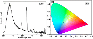 | ||
| Fig. 2 Luminescence characteristics of sample La100: (a) emission spectrum, and (b) the location of its light blue emission on the CIE 1931 colour diagram. | ||
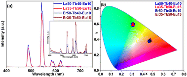
The emission colour could then be efficiently controlled by substituting La partly or fully with different combinations of Er, Tb and Eu in the Ln-terephthalate films, see Table 1. When part of La was substituted with Tb and Eu (samples La50-Tb40-Eu10 and La35-Tb50-Eu15 in Table 1) the excitation energy of the terephthalate moiety is apparently transferred to the lanthanides and the emission colour thereby shifted from the light blue to the green area, as illustrated in Fig. 3. The emission peaks seen for these samples at ca. 490 and 545 nm are assigned to Tb3+ emission (transitions 5D4 → 7F6 and 5D4 → 7F5. respectively), while the ones at ca. 615 and 700 nm are characteristic for Eu3+ (transitions 5D0 → 7F2 and 5D0 → 7F4 respectively). It is interesting to note that the green-to-red emission ratio is amazingly high in these samples.
To obtain warm white light for our Ln-terephthalate films, we replaced La with Er as the host lanthanide species. The non-substituted Er-terephthalate film (sample Er100 in Table 1) was found to be non-emissive in the visible region, lacking the broad emission band seen for the La-terephthalate film. This implies that the excitation energy of terephthalate is transferred to Er3+ ions. We thus assume that we should see emission in the IR range as the strongest emission from Er3+ is often seen around 1500 nm. This was however not verified as our focus in this work was on the visible range (white light luminescence).
By replacing La with Er in the Tb- and Eu-doped samples, we obtained warm white emission for samples Er50-Tb40-Eu10 and Er35-Tb50-Eu15, instead of the green emission seen for the corresponding La-based samples (Fig. 3). This denotes that Er3+ (while lacking the visible light emission on its own) affects the visible emission of Eu3+ and Tb3+ in our Ln-terephthalate thin films. This could possibly be due to energy transfer between Er3+, Tb3+ and Eu3+. It is evident from the emission spectra that the green-to-red and blue-to-red ratios decrease significantly upon the Er-for-La replacement, to the point that samples show more red than green emission. This implies that Er3+ diminishes the Tb3+ luminescence by absorbing some of the energy. The green-to-red ratio decreases more than the blue-to-red ratio, which explains why the films with Er are more in the warm white region of the spectrum than in the yellow, orange, or yellowish-green regions. Nevertheless, it is evident from the emission spectra that the intensity of the emission of Eu3+/Tb3+-doped Er-terephthalate films is significantly weaker compared to the La-based ones. These thin films also show a relatively weak quantum yield of ca. 0.5%.
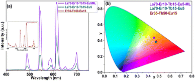
To overcome the sharp decline in emission intensity upon replacing La with Er, we deposited samples that contained both La and Er together with the emissive Tb3+ and Eu3+ ions, i.e. samples La70-Er10-Tb15-Eu5 and La70-Er10-Tb15-Eu5-ML. Note that the overall Ln composition is the same in these two samples, but the former is homogeneous while the latter is a three-layer sample, as illustrated in Fig. 4. The idea for the multi-layering was – while keeping the overall film thickness and overall elemental content the same – to generate areas in the film (in the middle layer) in which there would be relatively similar and even concentrations of all the four lanthanides. Our hypothesis was that this closer proximity of the different Ln species would enhance the energy transfer; indeed, the obtained results tentatively indicate that this could be the case, as will be explained in the following paragraphs. Here, it should be just mentioned that the exact individual layer thicknesses were defined on practical bases, to be able to design feasible precursor pulsing sequences within each (relatively thin) layer.
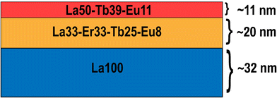 | ||
| Fig. 4 Schematic illustration of the three-layer composition of the multilayer La70-Er10-Tb15-Eu5-ML film, of the overall thickness of 63 nm. | ||
Both the samples, La70-Er10-Tb15-Eu5 and La70-Er10-Tb15-Eu5-ML, yield a warm white colour, see the CIE colour map in Fig. 5. Most remarkably, they possess the merits of both the La-terephthalate and the Er-terephthalate systems, i.e. the high emission intensity like in the La-based samples, and nearly an even green-to-red emission for the three-layer sample La70-Er10-Tb15-Eu5-ML due to the presence of erbium. Moreover, on the CIE colour map the colour is shifted a little towards the center of the map.
The homogeneous La70-Er10-Tb15-Eu5 sample shows a significantly reduced blue emission, and significantly high red emission, being the only sample with more red emission than green. This is the reason for the warm white emission, which is leaning more towards the orange-red part of the CIE colour map. The three-layer La70-Er10-Tb15-Eu5-ML sample, on the other hand, shows significantly more intense emission, with an almost equal red to green emission, the blue emission intensity being slightly decreased, which results in the warm white emission closer to the yellow-orange range on the CIE 1931 colour map. Additionally, it shows an improved quantum yield of ca. 2%. Often, the quantum yields of Ln-doped polymeric films are in the range of a few percent. Thus, the films of the present work show a typical performance in terms of the efficiency of light production. Still, much higher quantum yields of a few tens of percent have also been reported for white-emitting films doped with multiple lanthanides.40–42 However, it is to be noted that the intensity of luminescence is highly dependent on the number of emitters exposed to the excitation. Thus, the very thin films presented in this work are not expected to have such high quantum efficiencies.
Finally, we compare the emission colour, colour correlated temperature and colour rendering index of our La70-Er10-Tb15-Eu5-ML sample with the data obtained for commercial white LED lamps, incandescent bulbs, and fluorescent tubes, see Fig. 6 and Table 2. From Table 2, it is seen that our sample exceeds the commercial LED and fluorescent tube in the colour rendering index (CRI) metric; it should be emphasized that CRI values 80–100 are considered excellent. The incandescent bulb, as expected, shows a CRI of 100, thanks to the tungsten filament used which makes the emission the closest to black body radiation.43 Further improvement of the CRI of our sample may be achieved through careful fine-tuning of the lanthanide composition or looking for organic components matching with different excitation wavelengths.44
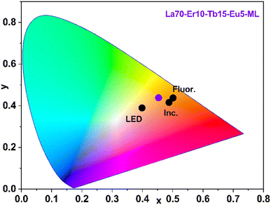 | ||
| Fig. 6 CIE colour map showing the comparison of our La70-Er10-Tb15-Eu5-ML sample (violet point) with commercial LED lamp (LED), fluorescent tube (Fluor.) and incandescent bulb (Ins.). | ||
| Sample | (x, y) | CCT/K | CRI |
|---|---|---|---|
| La70-Er10-Tb15-Eu5-ML | (0.45, 0.43) | 2890 | 88 |
| Incandescent bulb (Inc.) | (0.49, 0.42) | 2390 | 100 |
| Fluorescent tube (Fluor.) | (0.50, 0.44) | 2400 | 86 |
| LED lamp (LED) | (0.40, 0.39) | 3650 | 83 |
From Fig. 6, our La70-Er10-Tb15-Eu5-ML sample has lower (x, y) values than the incandescent bulb and the fluorescent tube but higher values than the LED lamp. These CIE diagram coordinates represent red (x) and green (y) colours, each normalized to the blue colour. A high x value means more red colour, while a high y value means more green colour; low values on both would mean more blue.45 The warmer white light of the present La70-Er10-Tb15-Eu5-ML thin film in comparison to the LED lamp is also seen from its lower CCT (colour correlated temperature) value (Table 2).46
4 Conclusions
We have demonstrated the single-step ALD/MLD fabrication of high-quality Ln-terephthalate thin films with multiple lanthanide constituents, in which up to four different lanthanides (La, Er, Eu, and Tb) are either homogeneously distributed or divided into multiple (three) different layers. This allowed us to control the Ln3+-ion composition and thereby the photoluminescence emission colour of the films.For the four-Ln-component (La,Er,Tb,Eu)-terephthalate thin films, intense warm-white-light emission was successfully realized. For the multi-layer La70-Er10-Tb15-Eu5-ML sample, the emission colour characteristics were comparable (and even exceeding) to those measured for commercial incandescent bulbs, fluorescent tubes and LED lamps.
The organic (terephthalate) component in the films was found to have manifold roles. First, it increases the distances between lanthanide ions such that the concentration quenching effect seen for example in simple lanthanide oxides is efficiently suppressed. Also, the terephthalate unit shows upon UV excitation UV/blue broad-band emission around 300–450 nm; in the erbium-containing films, this excitation energy was found to be efficiently transferred to the Er3+ ions and the emission may thereby be shifted to the longer wavelengths. Moreover, the organic components make the films mechanically flexible.
Since these flexible warm-white-light-emitting lanthanide-terephthalate thin films can in principle be deposited on a wide variety of substrate materials including polymers and textiles directly from gaseous/vaporized precursors at a relatively low temperature (190 °C) in a manner compatible e.g. with microelectronics industry, we foresee that the present approach could open up new horizons for advanced applications benefitting from high-quality flexible ultrathin white-light-emitting coatings.
Conflicts of interest
There are no conflicts to declare.Acknowledgements
We acknowledge the funding from the Academy of Finland (PREIN Flagship), and the use of the RawMatTERS Finland Infrastructure (RAMI) at Aalto University. A. G. acknowledges Jenny & Antti Wihuri foundation for financial support.References
- M. Pan, W. M. Liao, S. Y. Yin, S. S. Sun and C. Y. Su, Chem. Rev., 2018, 118, 8889–8935 CrossRef CAS PubMed.
- O. Kotova, S. Comby, C. Lincheneau and T. Gunnlaugsson, Chem. Sci., 2017, 8, 3419–3426 RSC.
- Z. He, W. Zhao, J. W. Y. Lam, Q. Peng, H. Ma, G. Liang, Z. Shuai and B. Z. Tang, Nat. Commun., 2017, 8, 1–8 CAS.
- R. A. Tigaa, X. Aerken, A. Fuchs and A. de Bettencourt-Dias, Eur. J. Inorg. Chem., 2017, 5310–5317 CrossRef CAS.
- S. Sahoo, S. Mondal and D. Sarma, Coord. Chem. Rev., 2022, 470, 214707 CrossRef CAS.
- M. Safdar, A. Ghazy, M. Lastusaari and M. Karppinen, J. Mater. Chem. C, 2020, 8, 6946–6965 RSC.
- P. Chen and N. Holten-Andersen, Adv. Opt. Mater., 2015, 3, 1041–1046 CrossRef CAS.
- J. Andres and A.-S. Chauvin, Molecules, 2020, 25, 4022 CrossRef CAS PubMed.
- A. C. Duke, S. Hariyani and J. Brgoch, Chem. Mater., 2018, 30, 2668–2675 CrossRef CAS.
- M. Zhao, Z. Yang, L. Ning and Z. Xia, Adv. Mater., 2021, 33, 2101428 CrossRef CAS PubMed.
- X. Min, M. Fang, Z. Huang, Y. Liu, C. Tang and X. Wu, J. Am. Ceram. Soc., 2015, 98, 788–794 CrossRef CAS.
- V. Kumar, V. Bhardwaj and A. Kaushik, ACS Appl. Electron. Mater., 2021, 3, 2261–2267 CrossRef CAS.
- Z. Zhang, Y. Chen, H. Chang, Y. Wang, X. Li and X. Zhu, J. Mater. Chem. C, 2020, 8, 2205–2210 RSC.
- N. S. Singh, N. K. Sahu and D. Bahadur, J. Mater. Chem. C, 2013, 2, 548–555 RSC.
- S. Xu, Z. Wang, P. Li, T. Li, Q. Bai, J. Sun and Z. Yang, J. Am. Ceram. Soc., 2017, 100, 2069–2080 CrossRef CAS.
- M. Mungra, F. Steudel, B. Ahrens and S. Schweizer, J. Lumin., 2017, 192, 71–76 CrossRef CAS.
- A. Górny, M. Sołtys, J. Pisarska and W. A. Pisarski, Opt. Appl., 2019, 49, 383–391 Search PubMed.
- F. González, R. López-Juárez, H. D. Orozco-Hernández, J. Zarate-Medina, R. Khadka, J. Collins and B. Di Bartolo, Ceram. Int., 2018, 44, 17681–17687 CrossRef.
- D. Ma, X. Li and R. Huo, J. Mater. Chem. C, 2014, 2, 9073–9076 RSC.
- J. Tang, Z. Liang, M. Huang, S. Su, Y. Wen, Q. L. Zhu and X. Wu, J. Mater. Chem. C, 2021, 9, 14628–14636 RSC.
- J. C. G. Bünzli, Coord. Chem. Rev., 2015, 293–294, 19–47 CrossRef.
- S. Dang, J. H. Zhang and Z. M. Sun, J. Mater. Chem., 2012, 22, 8868–8873 RSC.
- Y. Yang, L. Chen, F. Jiang, M. Yu, X. Wan, B. Zhang and M. Hong, J. Mater. Chem. C, 2017, 5, 1981–1989 RSC.
- S. M. George, Chem. Rev., 2010, 110, 111–131 CrossRef CAS PubMed.
- H. Van Bui, F. Grillo and J. R. Van Ommen, Chem. Commun., 2017, 53, 45–71 RSC.
- T. Yoshimura, S. Tatsuura and W. Sotoyama, Appl. Phys. Lett., 1991, 59, 482–484 CrossRef CAS.
- O. Nilsen, K. Klepper, H. Nielsen and H. Fjellvaåg, ECS Trans., 2008, 16, 3–14 CrossRef CAS.
- P. Sundberg and M. Karppinen, Beilstein J. Nanotechnol., 2014, 5, 1104–1136 CrossRef PubMed.
- J. Multia and M. Karppinen, Adv. Mater. Interfaces, 2022, 9, 2200210 CrossRef CAS.
- A. Philip, J. P. Niemelä, G. C. Tewari, B. Putz, T. E. J. Edwards, M. Itoh, I. Utke and M. Karppinen, ACS Appl. Mater. Interfaces, 2020, 12, 21912–21921 CrossRef CAS PubMed.
- J. P. Niemelä, A. Philip, N. Rohbeck, M. Karppinen, J. Michler and I. Utke, ACS Appl. Nano Mater., 2021, 4, 1692–1701 CrossRef.
- M. Tuomisto, Z. Giedraityte, M. Karppinen and M. Lastusaari, Phys. Status Solidi RRL, 2017, 11, 1700076 CrossRef.
- M. Leskelä, M. Mattinen and M. Ritala, J. Vac. Sci. Technol., B, 2019, 37, 030801 CrossRef.
- Z. Giedraityte, M. Tuomisto, M. Lastusaari and M. Karppinen, ACS Appl. Mater. Interfaces, 2018, 10, 8845–8852 CrossRef CAS PubMed.
- A. Ghazy, M. Safdar, M. Lastusaari and M. Karppinen, Chem. Commun., 2019, 56, 241–244 RSC.
- M. Safdar, A. Ghazy, M. Tuomisto, M. Lastusaari and M. Karppinen, J. Mater. Sci., 2021, 56, 12634–12642 CrossRef CAS.
- P. A. Hansen, J. Svendsen, H. Nesteng and O. Nilsen, RSC Adv., 2022, 12, 18063–18071 RSC.
- Z. Giedraityte, P. Sundberg and M. Karppinen, J. Mater. Chem. C, 2015, 3, 12316–12321 RSC.
- J. Penttinen, M. Nisula and M. Karppinen, Chem. – Eur. J., 2017, 23, 18225–18231 CrossRef CAS PubMed.
- R. Boddula, J. Tagare, K. Singh and S. Vaidyanathan, Mater. Chem. Front., 2021, 5, 3159–3175 RSC.
- H. Brunckova, E. Mudra, L. Rocha, E. Nassar, W. Nascimento, H. Kolev, A. Kovalcikova, Z. Molcanova, M. Podobova and L. Medvecky, Appl. Surf. Sci., 2021, 542, 148731 CrossRef CAS.
- O. Kotova, S. J. Bradberry, A. J. Savyasachi and T. Gunnlaugsson, Dalton Trans., 2018, 47, 16377–16387 RSC.
- W. Davis and Y. Ohno, J. Mod. Opt., 2009, 56, 1412–1419 CrossRef.
- D. F. Sava, L. E. S. Rohwer, M. A. Rodriguez and T. M. Nenoff, J. Am. Chem. Soc., 2012, 134, 3983–3986 CrossRef CAS PubMed.
- D. A. Kerr, Colorimetry, 2010, 1, 1–16 Search PubMed.
- D. Durmus, Light. Res. Technol., 2022, 54, 363–375 CrossRef.
Footnote |
| † Electronic supplementary information (ESI) available. See DOI: https://doi.org/10.1039/d3tc00464c |
| This journal is © The Royal Society of Chemistry 2023 |

