Computing metasurface capable of broad-band switchable anisotropic edge-enhanced imaging

Qun Hao a, Wenli Wang a, Jing Wang b, Qianhui Li a, Yao Hu *a, Shaohui Zhang a and Liandong Yu b
aBeijing Key Laboratory for Precision Optoelectronic Measurement Instrument and Technology, School of Optics and Photonics, Beijing Institute of Technology, Beijing 100081, China. E-mail: huy08@bit.edu.cn
bCollege of Control Science and Engineering, China University of Petroleum, No. 66, West Changjiang Road, Qingdao, 266580, China

Received 9th January 2023 , Accepted 28th February 2023

First published on 28th February 2023


Abstract

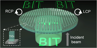
Anisotropic edge enhancement imaging along different directions possesses the capability to extract different morphological information from an object which plays a vital role in weak edge detection in imaging. Building a simple, miniature, switchable anisotropic edge enhancement imaging device is extremely absorbing. Here, we design a 2D material, i.e., a helicity-multiplexing dielectric metasurface for anisotropic edge-enhanced imaging. More importantly, this 2D material is prioritized to satisfy two sets of unrelated phase profiles, relying on different helicities of the incident beam. It can function as two different anisotropic edge enhancement filters along different directions by incorporating the 4f imaging system and dynamically switching its function by altering the helicity of the incident beam. Furthermore, a hybrid imaging device based on this 2D material can work across a visible broadband spectrum, which is potentially applicable in biomedical imaging and optical analog computing.

Introduction

Fast and reliable anisotropic edge detection and image processing are vital capabilities required in biomedical imaging1,2 and outdoor infrared detection.3 Many digital domain computations using integrated circuits have been proposed for enhancing imaging detection at the expense of high-power consumption and low speed.4,5 Optical analog computing can overcome these limits because it modulates the field of the incident beam by placing appropriate optical elements in the optical system.6 In this regard, many image edge detection approaches based on optical computing have been demonstrated, such as conventional phase contrast imaging,7–10 the photonics spin Hall effect,11 the Goos–Hänchen effect,12 the Brewster effect13 and other novel methods,4 which are state-of-the-art technologies and most of which are utilized to achieve typical isotropic edge enhancement. Therefore, these approaches are not perfectly suited to some imaging cases where some directions with weak edges need to be preferentially emphasized more than other directions.

With further research on radial unsymmetric Hilbert transform filtering, two represented anisotropic edge detection methods, fractional vortex beam14,15 and shifted vortex beam16,17 approaches, have been demonstrated. Among them, the shifted vortex beam approach is conducted by interpreting the general radial Hilbert transform filtering as the format of a vortex and shifting the original position of singularity to break the symmetry of filtering.16,17 In this way, the orientation of edge enhancement can be efficiently changed and can lead to strong anisotropic contrast imaging. Moreover, this unsymmetric Hilbert transform can immensely decline the data and procedures of imaging processing as it only extracts an image's important edge information and highlights the edges in need. However, to date, the function implementation of the anisotropic edge enhancement based on the above-mentioned methods is mainly by using a liquid crystal-based spatial light modulator, which provides dynamic phase or amplitude modulation for the optical input field by precision voltage regulation.18 Therefore, it is not convenient enough compared with simple mode regulation of incident beams. Meanwhile, its bulky configuration and limited resolution hinder its applications in modern miniaturized and integrated systems.16,19,20 Thus, building a simple, miniature, high-resolution, switchable anisotropic edge enhancement system is extremely absorbing.

Metasurfaces, composed of specifically designed subwavelength units in a two-dimensional plane, have become research hotspots due to their tremendous power in manipulating optical wavefronts.21–25 They can replace several bulky traditional optical components to achieve various optical functions and allow light to be precisely regulated in the sub-wavelength thickness range. These potentials have pushed metasurfaces into different research areas, such as investigating the spin Hall effect,26,27 tailoring multiple vortex beams,28–30 metalenses31,32 and metaholograms.33–35 Meanwhile, a variety of functional imaging techniques based on metasurfaces,36,37 like polarization imaging,38,39 spectral imaging,40,41 and isotropic edge detection,18,27,42–44 are all attractive. To our best knowledge, current 2D switchable anisotropic edge-enhancement imaging via a metasurface also requires an external liquid-crystal plate based on additional voltage modulation.45 Fortunately, the development of helicity-multiplexing metasurfaces brings great hope for this research.46–49

Here, a helicity-multiplexing metasurface (2D material) is designed based on the propagation phase and the geometry phase, which can dynamically switch between two various anisotropic edge enhancement filters only by transforming the polarization of the incident beam. This metasurface is composed of many nanopillars, which are all prioritized to be appropriate for two independent phase profiles. By embedding the metasurface into the focal plane of a Fourier transform in an optical system, we will demonstrate that this merging meta-4f imaging device enables the input field to achieve switchable 2D-anisotropic edge enhancement efficiently. The broadband characteristics will also be verified.

Principle and design

The overall design of the meta-4f system

Fig. 1 is the schematic of our meta-4f system setup, consisting of two traditional lenses and a helicity-multiplexing dielectric metasurface capable of dynamically switching between two different anisotropic edge enhancement imaging filters by changing the polarization of the incident beam. For example, as shown in Fig. 1(a), when the input object is the abbreviation “BIT”, and the polarization of the incident beam is left-handed circular polarized (LCP), the output image is a left-enhanced anisotropic edge image of the object. Similarly, when this input object is under the illumination of a right-handed circular polarized (RCP) incident beam, the output information presented is a right-enhanced anisotropic edge image of the object, as shown in Fig. 1(b). The curvilinear figures in Fig. 1(a) and (b), respectively, show the corresponding cross-sectional intensity distributions at the white dashed line of the image in Fig. 1(a) and (b). We can observe the edge enhancement's anisotropic characteristics (left or right enhancement) from these. Other anisotropic edge enhancements can also be tailored, which will be shown later.
image file: d3tc00092c-f1.tif
Fig. 1 Schematic of our meta-4f system setup. (a) A left-enhanced anisotropic edge image of the object “BIT” is obtained when illuminated by an LCP incident beam. (b) A right-enhanced anisotropic edge image of the object “BIT” is obtained when illuminated by an RCP incident beam. The curvilinear figures in the insets both represent the corresponding cross-sectional intensity distribution at the white dashed line of the image.

Principle of the meta-4f system

To illustrate the feasibility of our meta-4f system, we analyze the whole optical image processing of this system and the relevant principle in detail. In this system, the object can be seen as an electric field pattern of the LCP or RCP incident beam written as Ein(x, y), where x and y are respectively, the x or y-direction coordinates in the input or output image plane. Then, a spatial Fourier transformation is performed by lens1 in Fig. 1(a). Our designed helicity-multiplexing dielectric metasurface functions as a dynamic spatial filter. Its optical spectrum transfer function can be written as H(fx, fy), where fx and fy are spatial frequency coordinates in the Fourier plane. After being modulated by our special spatial filter, the tailored electric field pattern is manipulated by lens2 in Fig. 1(a), and an inverse spatial Fourier transformation is performed. Therefore, the whole optical image processing can be concluded as follows:
 
Eout(x, y) = IFT{H(fx, fy)·FT[Ein(x, y)]}(1)
where, FT represents the 2D spatial Fourier transformation, and IFT represents the 2D inverse spatial Fourier transformation.

Next, one of the design keys is finding a proper H(fx, fy) to help us efficiently achieve anisotropic edge enhancement. As mentioned above, a classical radial unsymmetric Hilbert transform16 based on a complex amplitude modulation has been mathematically demonstrated. It breaks down the symmetry of the Hilbert transform by shifting the original position of singularity, and its phase modulation is dominant. Inspired by this, we infer that we can add an external phase distribution to the general spiral phase distribution corresponding to the classical radial symmetric Hilbert transform. Then we can easily change the singularity position only based on phase modulation. To protect the entire spiral phase filtering properties, we utilize relevant coefficients like ρ0 to control the additional phase effect. So, our H(fx, fy) can be expressed as:

 
image file: d3tc00092c-t1.tif(2)
where, fx = u/(λf), fy = v/(λf), u and v are respectively the x or y-direction coordinates in the Fourier plane. Angle (·) represents the operation of extracting the phase of the expression in parentheses. ρ2 = u2 + v2, ϕ = arc[thin space (1/6-em)]tan(v/u), and ρ0 and θ are both real numbers. ρ12 = ρ2 + ρ02 + 2ρ0ρ[thin space (1/6-em)]cos(ϕθ). Normally, ρ0 is less than the maximum of ρ1/2. This way, several representative direction anisotropic edge enhancements can be efficiently achieved by changing the value of θ.

To observe this characteristic clearly, we keep ρ0 = 0.15 max(ρ1/2), choose different values of θ, and then gain several different distributions about H(fx, fy). Here, a circular pattern is used as the object Ein(x, y). We can calculate the corresponding output field patterns Eout(x, y) with the help of the MATLAB platform, as shown in Fig. 2. Fig. 2(a1)–(a4) displays the output field distributions when θ = π/4, π/2, 3π/4 and π. The corresponding cross-sectional intensity curves are shown in Fig. 2(b1)–(b4). Subsequently, when we use θ = 5π/4, 3π/2, 7π/4, and 2π, the obtained output field patterns and the corresponding cross-sectional intensity curves are respectively exhibited in Fig. 2(c1)–(c4) and (d1)–(d4). It can be found that there were various anisotropic edge enhancements along different directions when we changed the value of θ. In addition, we also observe the obtained theoretical results when different values of ρ0 are chosen, and θ is set as π. From Fig. S1 (ESI), different values of ρ0 can affect the contrast of the anisotropic edge enhancement (see Note 1 of ESI).


image file: d3tc00092c-f2.tif
Fig. 2 Demonstration of the theoretical output results corresponding to the designed H(fx, fy) when a circular pattern is the input object. (a1)–(a4) Theoretical output results as we set θ as π/4, π/2, 3π/4, π, respectively. (b1)–(b4) Cross-sectional intensity curves of (a1)–(a4) along the white dashed lines. (c1)–(c4) Theoretical output results as we set θ as 5π/4, 3π/2, 7π/4, and 2π, respectively. (d1)–(d4) Cross-sectional intensity curves of (c1)–(c4) along the white dashed lines.

Therefore, the required phase profiles for our helicity-multiplexing metasurface mentioned in Fig. 1 can be written like this:

 
image file: d3tc00092c-t2.tif(3)
 
image file: d3tc00092c-t3.tif(4)
where, ψ1 and ψ2 are respectively the required phase profiles when the polarization of the incident beam is LCP or RCP. The corresponding phase maps are shown in Fig. S2 (ESI).

Then, we divide the total phase of our metasurface into the propagation phase and the geometry phase, which can be respectively expressed18 with the phase profiles in eqn (3) and (4) as:

 
δx(x, y) = [ψ1(x, y) + ψ2(x, y)]/2(5)
 
δy(x, y) = [ψ1(x, y) + ψ2(x, y)]/2 − π(6)
 
2ϑ(x, y) = [ψ1(x, y) − ψ2(x, y)]/2(7)
where, δx and δy are the propagation phase distributions for a linear polarization incident beam in the x- and y-directions, respectively, and 2ϑ is the geometric phase distribution.

Design of the metasurface

Fig. 3(a) and (b) respectively show the side and vertical views of a specifically designed unit cell to conform to the required propagation and geometric phases. It is a simple titanium dioxide nanopillar fabricated on a glass substrate. These nanopillars are periodically distributed with a fixed square lattice constant Px = Py = 360 nm and a height H = 600 nm. By changing the nanopillar's length L, and width W, we can construct the whole propagation phase library for choosing proper δx and δy that satisfy the relationships in eqn (5) and (6). The simulated phase δx for a linear polarization incident beam in the x-direction (XLP) as a function of L and W is shown in Fig. 3(c), and the corresponding transmission coefficient distribution tx is displayed in Fig. 3(d). Homoplastically, the simulated phase δy and the corresponding transmission coefficient distribution ty for a linear polarization incident beam in the y-direction (YLP) are respectively exhibited in Fig. 3(e) and (f). Considering the geometric phase, its control mechanism is by rotating the rotation orientation angle ϑ of the nanopillars, and it is twice the rotation orientation angle ϑ so that it can easily cover the entire phase library. In addition, all nanopillars are constructed to work as half-wave plates to maximize their polarization conversion efficiency. Underlying the above mechanism, we can obtain any ideal phase combination (δx, δy, and 2ϑ) by picking up an appropriate size and a rotation orientation angle (L, W, and ϑ) of the nanopillar. In this way, we can design our helicity-multiplexing metasurface to meet the phase profiles in eqn (3) and (4). The working wavelength of the incident laser is 532 nm. The simulation results are calculated through the commercial software, FDTD- solutions, where perfectly matching layers are used in the x, y, and z directions, and plane-wave sources are utilized.
image file: d3tc00092c-f3.tif
Fig. 3 (a) Side and (b) vertical view of a typical unit cell of the helicity-multiplexing metasurface with the period (Px, Py), height (H), varying cross section sizes (L and W), and different orientation rotation angles (ϑ). (c) Simulated propagation phase δx and (d) transmission coefficient tx distributions for an XLP incident beam. (e) Simulated propagation phase δy and (f) transmission coefficient ty distributions for a YLP incident beam.

Results

Fig. 4(a) and (b) respectively show the far-field phase distributions of the vortex beam generated by our metasurface (metasurface 1) when illuminated by an LCP or RCP incident beam. The spiral phase distributions in these two subfigures are different. Still, the corresponding intensity patterns in the center of the far-field intensity distributions are approximately equal (Fig. 4(c) and (d)). It means that our anisotropic edge enhancements are mainly manipulated by the pure phase, demonstrating the modulation mechanism that we mentioned in the section “Principle and design”. Additionally, we also calculated the generated near-field phase profiles. The phase patterns maintain the spiral characteristic, and they are basically similar to our designed phase maps in eqn (3) and (4) (see Note 2 of ESI). To evaluate the feasibility of our approach comprehensively, we also simulated the whole process. Fig. 4(e) and (f) are intensity distributions of the output field of the meta-4f system calculated by eqn (1), where the commercial software MATLAB is used to perform positive and inverse spatial Fourier transformations. When the polarization of the incident beam is LCP, the output RCP field intensity distribution is a left-enhanced anisotropic edge image of the abbreviation “BIT” as shown in Fig. 4(e). Similarly, when illuminated by the RCP incident beam, the output LCP field intensity pattern is a right-enhanced anisotropic edge image of “BIT,” as shown in Fig. 4(f). Fig. 4(g) and (h) are respectively cross-sectional intensity distributions at the white dashed line position in Fig. 4(e) and (f), from which we can see the anisotropic edge enhancements in different directions more clearly. Therefore, this meta-4f system can achieve dynamic anisotropic edge enhancements by changing the polarization of the incident beam.
image file: d3tc00092c-f4.tif
Fig. 4 (a) Simulated far-field phase distribution of metasurface 1 under the illumination of an LCP incident beam and (b) simulated far-field phase distribution of metasurface 1 under the illumination of an RCP incident beam; (c) and (d) depict the corresponding intensity patterns in the center of the far-field intensity distributions. (e) Output RCP field intensity distribution with a left enhanced edge of our meta-4f system under the illumination of an LCP incident beam and (f) output LCP field intensity distribution with a right enhanced edge of our meta-4f system under the illumination of an RCP incident beam. (g) and (h) Cross-sectional intensity distributions at the white dashed line position in (e) and (f), respectively.

Furthermore, to verify our method's viability in achieving switchable anisotropic edge enhancements along other directions, we designed another metasurface (metasurface 2), which aims to achieve anisotropic edge enhancements along both horizontal and vertical directions. Therefore, the required phase profiles can be deduced like this:

 
ψ1 = angle[(ρ[thin space (1/6-em)]exp(iϕ) + (ρ0[thin space (1/6-em)]exp(iπ/2))/ρ1](8)
 
ψ2 = angle[(ρ[thin space (1/6-em)]exp(iϕ) + (ρ0[thin space (1/6-em)]exp(i2π))/ρ1](9)
ψ1 and ψ2 are respectively shown in Fig. S2 (ESI). The corresponding near-field phase distributions generated by metasurface 2 are also shown in Fig. S2 (ESI), the spiral characteristics of which are well-maintained and generally similar to the phase maps in eqn (8) and (9) (see Note 2 of ESI). The other simulated results are shown in Fig. 5. Fig. 5(a) and (b) respectively show the far-field phase patterns of the vortex beam generated by our metasurface under the illumination of an LCP or RCP incident beam. The spiral phase distributions in these two subfigures are also diverse, contributing to different anisotropic edge enhancements. Fig. 5(c) and (d) depict the corresponding intensity patterns in the center of the far-field intensity distributions, which are approximately equal. In addition, simulations of the whole process are also performed. Fig. 5(e) and (f) are output field patterns of the meta-4f system calculated by using eqn (1). The output RCP field intensity pattern is a right-enhanced anisotropic edge image of “BIT” under the illumination of an LCP incident beam, as shown in Fig. 5(e). When illuminated by the RCP incident beam, the output LCP field intensity pattern is a top-enhanced anisotropic edge image of “BIT,” as shown in Fig. 5(f). Fig. 5(g) and (h) are respectively cross-sectional intensity distributions at the white dashed line position in Fig. 5(e) and (f). Thus, our approach can be utilized to design different metasurfaces for realizing various switchable anisotropic edge-enhanced imaging.


image file: d3tc00092c-f5.tif
Fig. 5 (a) Simulated far-field phase distribution of metasurface 2 under the illumination of an LCP incident beam and (b) simulated far-field phase distribution of metasurface 2 under the illumination of an RCP incident beam; (c) and (d) depict the corresponding intensity patterns in the center of the far-field intensity distributions. (e) Output RCP field intensity distribution with a right enhanced edge of our meta-4f system under the illumination of an LCP incident beam and (f) output LCP field intensity distribution with a top enhanced edge of our meta-4f system under the illumination of an RCP incident beam. (g) and (h) Cross-sectional intensity distributions at the white dashed line position in (e) and (f), respectively.

Since the geometry phase can work in a wide wavelength span, we infer that our designed helicity-multiplexing metasurfaces based on the propagation phase and the geometry phase can also work across broadband. To demonstrate the broadband functionalities of our meta-4f imaging system, another object, “M&I”, the abbreviation for our laboratory, is used as an imaging target and is illuminated by beams of different wavelengths of 480 nm, 532 nm, and 630 nm. Metasurface 1 is picked out as the spatial filter in the Fourier plane. The near-field phase patterns of the vortex beam generated by metasurface 1 under the illumination of 480 and 630 nm incident beams are shown respectively in Fig. S3 (ESI). It is obvious that the spiral characteristics of the near-field distributions under the illumination of 480 nm are well-maintained, and their phase patterns are similar to those under the illumination of 532 nm. These absolute values of the near-field distributions at the wavelength of 630 nm are not similar enough to the results at the wavelength of 532 nm. Still, the spiral characteristics are well-maintained, i.e., they are similar to those under the illumination of 532 nm, which is the key point at work. Fig. 6(a)–(c) show respectively the output RCP field intensity information of our meta-4f system under the illumination of LCP incident beams at wavelengths of 480 nm, 532 nm, and 630 nm. Fig. 6(d)–(f) show respectively the cross-sectional intensity distributions at the white dashed line positions in Fig. 6(a)–(c), from which it is obvious that left-enhancement anisotropic edge images can all be extracted. Similarly, Fig. 6(g)–(i) show respectively the output LCP field information of our meta-4f system under the illumination of RCP incident beams at a wavelengths of 480 nm, 532 nm, and 630 nm. Fig. 6(j)–(l) show respectively the cross-sectional intensity distributions at the white dashed line positions in Fig. 6(g)–(i), from which it is obvious that the right-enhancement anisotropic edge images can all be extracted. Therefore, our designed meta-4f system is not restricted to a specific wavelength and has a working bandwidth of at least 150 nm.


image file: d3tc00092c-f6.tif
Fig. 6 (a)–(c) Output RCP field information of our meta-4f system under the illumination of an LCP incident beam at wavelengths of 480 nm, 532 nm, and 630 nm, respectively. (d)–(f) Field intensity distributions at the white dashed line position in (a)–(c), respectively. (g)–(i) Output LCP field information of our meta-4f system under the illumination of an RCP incident beam at wavelengths of 480 nm, 532 nm, and 630 nm. (j)–(l) Field intensity distributions at the white dashed line position in (g)–(i), respectively.

Conclusion

In conclusion, we have proposed and demonstrated a relevant 2D material, i.e., two dielectric helicity-multiplexing metasurfaces, based on our proposed method. These metasurfaces can dynamically switch between two different functions (i.e., generating different vortex beams) by altering two different polarizations of the incident beam, which correspond to two unrelated phase profiles. By endowing these metasurfaces with two different phase profiles and merging them into the 4f imaging system, we have demonstrated that this meta-4f imaging device can achieve two anisotropic edge enhancements along specific directions, including left and right or right and top. Furthermore, the broadband characteristics of our imaging device have been verified. Combined with the advantages of planar architecture and dynamically switchable functionalities across a broadband of the metasurface, we can envision that this meta-4f imaging device based on a designed 2D material holds potential applications in biomedical imaging and optical analog computing.

Author contributions

Qun Hao: supervised the overall study; Wenli Wang: performed the calculations and numerical analyses and finished the manuscript; Yao Hu: designed the simulations and finished the manuscript revisions; Jing Wang: finished the discussion of the frame of the manuscript and participated in the numerical analyses; Qianhui Li and Shaohui Zhang: participated in the manuscript revisions; Liandong Yu: participated in designing the frame of the manuscript.

Conflicts of interest

There are no conflicts to declare.

Acknowledgements

This work was supported by the National Natural Science Foundation of China (Grant No. 51735002, 62275022).

References

  1. S. T. Acton and K. Ley, in IEEE International Conference on Image Processing, 2001, vol. 2, pp. 300–303.
  2. A. H. Hernandez, D. G. Gill, P. R. Radeva and E. N. Nofrerias, in Computers in Cardiology, 2004, IEEE, pp. 229–232.
  3. S. Hai-jiang, W. Yan-jie and C. Xiao-lin, Opt. Precis. Eng, 2014, 22, 146–151 CrossRef.
  4. H. Kwon, D. Sounas, A. Cordaro, A. Polman and A. Alù, Phys. Rev. Lett., 2018, 121, 173004 CrossRef CAS PubMed.
  5. T. J. Davis, F. Eftekhari, D. E. Gómez and A. Roberts, Phys. Rev. Lett., 2019, 123, 013901 CrossRef CAS PubMed.
  6. D. R. Solli and B. Jalali, Nat. Photonics, 2015, 9, 704–706 CrossRef CAS.
  7. F. Zernike and F. J. M. Stratton, Mon. Not. R. Astron. Soc., 1934, 94, 377–384 CrossRef.
  8. J. G. Dodd, Appl. Opt., 1977, 16, 470–472 CrossRef CAS.
  9. S. N. Khonina, V. V. Kotlyar, M. V. Shinkaryev, V. A. Soifer and G. V. Uspleniev, J. Mod. Opt., 1992, 39, 1147–1154 CrossRef.
  10. J. A. Davis, D. E. McNamara, D. M. Cottrell and J. Campos, Opt. Lett., 2000, 25, 99–101 CrossRef CAS PubMed.
  11. S. He, J. Zhou, S. Chen, W. Shu, H. Luo and S. Wen, APL Photonics, 2020, 5, 036105 CrossRef CAS.
  12. D. Xu, S. He, J. Zhou, S. Chen, S. Wen and H. Luo, Appl. Phys. Lett., 2020, 116, 211103 CrossRef CAS.
  13. T. Zhu, C. Guo, J. Huang, H. Wang, M. Orenstein, Z. Ruan and S. Fan, Nat. Commun., 2021, 12, 680 CrossRef CAS PubMed.
  14. A. W. Lohmann, D. Mendlovic and Z. Zalevsky, Opt. Lett., 1996, 21, 281–283 CrossRef CAS PubMed.
  15. J. Wang, W. Zhang, Q. Qi, S. Zheng and L. Chen, Sci. Rep., 2015, 5, 15826 CrossRef CAS.
  16. G. Situ, G. Pedrini and W. Osten, J. Opt. Soc. Am. A, 2009, 26, 1788–1797 CrossRef PubMed.
  17. M. K. Sharma, J. Joseph and P. Senthilkumaran, J. Opt., 2013, 42, 1–7 CrossRef.
  18. P. Huo, C. Zhang, W. Zhu, M. Liu, S. Zhang, S. Zhang, L. Chen, H. J. Lezec, A. Agrawal, Y. Lu and T. Xu, Nano Lett., 2020, 20, 2791–2798 CrossRef CAS.
  19. A. Jesacher, S. Fürhapter, S. Bernet and M. Ritsch-Marte, Phys. Rev. Lett., 2005, 94, 233902 CrossRef PubMed.
  20. C. Maurer, A. Jesacher, S. Bernet and M. Ritsch-Marte, Laser Photon. Rev., 2011, 5, 81–101 CrossRef.
  21. D. Lin, P. Fan, E. Hasman and M. L. Brongersma, Science, 2014, 345, 298–302 CrossRef CAS.
  22. S. Kruk and Y. Kivshar, ACS Photonics, 2017, 4, 2638–2649 CrossRef CAS.
  23. S. Divitt, W. Zhu, C. Zhang, H. J. Lezec and A. Agrawal, Science, 2019, 364, 890–894 CrossRef CAS.
  24. M. Pan, Y. Fu, M. Zheng, H. Chen, Y. Zang, H. Duan, Q. Li, M. Qiu and Y. Hu, Light: Sci. Appl., 2022, 11, 195 CrossRef CAS.
  25. H. Jeong, Y. Yang, H. Cho, T. Badloe, I. Kim, R.-M. Ma and J. Rho, Microelectron. Eng., 2020, 220, 111146 CrossRef CAS.
  26. X. Yin, Z. Ye, J. Rho, Y. Wang and X. Zhang, Science, 2013, 339, 1405–1407 CrossRef CAS.
  27. J. Zhou, H. Qian, C.-F. Chen, J. Zhao, G. Li, Q. Wu, H. Luo, S. Wen and Z. Liu, Proc. Natl. Acad. Sci. U. S. A., 2019, 116, 11137–11140 CrossRef CAS.
  28. Y. Bao, J. Ni and C. Qiu, Adv. Mater., 2020, 32, 1905659 CrossRef CAS.
  29. H. Yang, Z. Xie, G. Li, K. Ou, F. Yu, H. He, H. Wang and X. Yuan, Photonics Res., 2021, 9, 331–343 CrossRef.
  30. Q. Hao, W. Wang, Y. Hu, S. Zhang, S. Zhang and Y. Zhang, Opt. Mater. Express, 2022, 12, 3872–3881 CrossRef CAS.
  31. M. Khorasaninejad, W. T. Chen, R. C. Devlin, J. Oh, A. Y. Zhu and F. Capasso, Science, 2016, 352, 1190–1194 CrossRef CAS PubMed.
  32. K. Ou, F. Yu, G. Li, W. Wang, A. E. Miroshnichenko, L. Huang, P. Wang, T. Li, Z. Li, X. Chen and W. Lu, Sci. Adv., 2020, 6, eabc0711 CrossRef CAS.
  33. X. Fang, H. Ren and M. Gu, Nat. Photonics, 2020, 14, 102–108 CrossRef CAS.
  34. X. Li, X. Zhang, R. Zhao, G. Geng, J. Li, L. Huang and Y. Wang, Laser Photon. Rev., 2022, 16, 2100592 CrossRef.
  35. J. Burch, J. Ma, R. I. Hunter, S. A. Schulz, D. A. Robertson, G. M. Smith, J. Wang and A. D. I. Falco, Appl. Phys. Lett., 2019, 115, 021104 CrossRef.
  36. K. Cheng, Z. Li, J. Wu, Z.-D. Hu and J. Wang, Opt. Express, 2022, 30, 2780–2791 CrossRef CAS PubMed.
  37. M. Li, M. Liu, Y. Chen, Z. Da Hu, J. Wu and J. Wang, Nanoscale Res. Lett., 2022, 17, 81 CrossRef CAS PubMed.
  38. N. A. Rubin, G. D’Aversa, P. Chevalier, Z. Shi, W. T. Chen and F. Capasso, Science, 2019, 365, eaax1839 CrossRef CAS.
  39. Y. Hu, X. Wang, X. Luo, X. Ou, L. Li, Y. Chen, P. Yang, S. Wang and H. Duan, Nanophotonics, 2020, 9, 3755–3780 CrossRef.
  40. A. McClung, S. Samudrala, M. Torfeh, M. Mansouree and A. Arbabi, Sci. Adv., 2020, 6, eabc7646 CrossRef CAS PubMed.
  41. X. Hua, Y. Wang, S. Wang, X. Zou, Y. Zhou, L. Li, F. Yan, X. Cao, S. Xiao, D. P. Tsai, J. Han, Z. Wang and S. Zhu, Nat. Commun., 2022, 13, 2732 CrossRef CAS.
  42. H. Yang, Z. Xie, H. He, Q. Zhang, J. Li, Y. Zhang and X. Yuan, Opt. Lett., 2021, 46, 3741–3744 CrossRef CAS PubMed.
  43. Z. Wang, G. Hu, X. Wang, X. Ding, K. Zhang, H. Li, S. N. Burokur, Q. Wu, J. Liu, J. Tan and C.-W. Qiu, Nat. Commun., 2022, 13, 2188 CrossRef CAS PubMed.
  44. T. Badloe, S. Lee and J. Rho, Adv. Photonics, 2022, 4, 064002 CAS.
  45. T. Xiao, H. Yang, Q. Yang, D. Xu, R. Wang, S. Chen and H. Luo, Opt. Lett., 2022, 47, 925–928 CrossRef CAS PubMed.
  46. T. Badloe, I. Kim, Y. Kim, J. Kim and J. Rho, Adv. Sci., 2021, 8, 2102646 CrossRef PubMed.
  47. M. A. Naveed, M. A. Ansari, I. Kim, T. Badloe, J. Kim, D. K. Oh, K. Riaz, T. Tauqeer, U. Younis, M. Saleem, M. S. Anwar, M. Zubair, M. Q. Mehmood and J. Rho, Microsyst. Nanoeng., 2021, 7, 5 CrossRef CAS PubMed.
  48. H. S. Khaliq, I. Kim, J. Kim, D. K. Oh, M. Zubair, K. Riaz, M. Q. Mehmood and J. Rho, Adv. Opt. Mater., 2021, 9, 2002002 CrossRef CAS.
  49. Y. Yang, H. Kim, T. Badloe and J. Rho, Nanophotonics, 2022, 11, 4123–4133 CrossRef CAS.

Footnote

Electronic supplementary information (ESI) available. See DOI: https://doi.org/10.1039/d3tc00092c

This journal is © The Royal Society of Chemistry 2023