Bacterial cellulose wave plates for polarization-encryption applications

Xiao Yu a, Dan Zhang a, Mengdi Xu a, Guangjie Song b and Yan Xu *a
aState Key Laboratory of Inorganic Synthesis and Preparative Chemistry, Jilin University, 2699 Qianjin Street, Changchun, 130012, P. R. China. E-mail: yanxu@jlu.edu.cn
bCAS Key Laboratory of Engineering Plastics, Institute of Chemistry, Chinese Academy of Sciences, Beijing, 100190, P. R. China

Received 2nd December 2022 , Accepted 11th January 2023

First published on 12th January 2023


Abstract

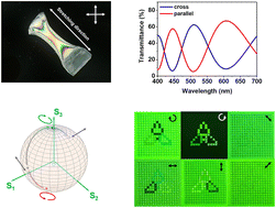
Bacterial cellulose (BC)-based wave plates with tunable phase delays from the visible to near-infrared region are developed. Simple wet stretching and filling with similar refractive index polymers endow BC nanocomposite films with orientational birefringence and high transparency. The BC-based wave plates showing precise control of the polarization state of polarized light are used for polarization-encryption applications.


Introduction

Wave plates are one of the indispensable parts of polarization optical systems and are widely used in circular polarizers, interferometers, and LCD devices for phase splitting or phase compensation.1–3 Wave plates with different phase delays can modulate the polarization state of the polarized light by changing the optical path difference, so as to realize multifarious polarization information.4 The resultant optical signal possessing a specific polarization state can be applied in the field of polarization-based encryption. To date, polarization-based encryption materials research has mainly focused on metasurfaces, which are two-dimensional wave plates composed of subwavelength shape-birefringent mosaics capable of modifying electromagnetic characteristics.5–7 Considering the cost and practical operability, more accessible wave plate materials are needed. Note that high optical transparency and birefringence are the two essential features of wave plates. A birefringent material will split light into two linearly polarized beams with vertical directions of vibration and different velocities. Inorganic crystals, such as gypsum or mica, were discovered whose birefringence originates from the intrinsic differences of principal dielectric coefficients in the crystalline lattice structure. Beyond that, polymers with orientational birefringence are also used for commercial wave plates.2

Cellulose is a primary biopolymer due to its economic importance and sustainability-related advantages. It is a linear homopolysaccharide composed of D-glucopyranose units that are connected by β-1,4 glucosidic bonds.8 Cellulose molecules with an anisotropic molecular configuration are assembled into cellulose nanofibres by inter- and intra-molecular hydrogen bonds.9 The parallel packing of molecular chains endows cellulose nanofibres with intrinsic birefringence, which is an extension of optical anisotropy from the molecular to mesoscopic scale.10,11 Currently, aligned plant-based cellulose nanocrystals have been used to make birefringent films for phase retardation.12,13 Apart from being the most important structural component of the primary cell wall of plants,14 cellulose can be synthesized by Gram-negative aerobic bacteria, such as Acetobacter xylinum, at the air–liquid interface of the culture medium containing carbon and nitrogen sources, known as bacterial cellulose (BC).15 Compared with plant cellulose, BC has higher crystallinity and does not contain any hemicellulose, lignin, and waxy materials.16 The development of BC-based products has been a subject of interest in materials science from both economic and environmental perspectives. In this context, much advance has been documented in the design and engineering of BC-based materials for diversified applications ranging from biomedicine, to cosmetics and electronics.17–19

BC is formed as a hydrous pellicle consisting of an interconnected network of nanofibres assembled in numerous dense layers under static cultivation conditions.20 Drying of the hydrous pellicle results in white BC paper due to its high porosity.21 Such BC paper is non-birefringent because random orientations of BC nanofibres cancel out the intrinsic optical anisotropies of individual cellulose nanofibres.2 Given these facts, BC-based optical materials remain largely unexplored. To endow BC paper with birefringence, unidirectional alignment of BC nanofibres is required. This has been made possible by the seminal paper of Colvin and coworkers,22 which has led to the development of oriented BC as a platform material in which the orientation of BC nanofibres can be in vivo engineered,23 or by mechanical stretching of BC pellicles.24,25 Transparent BC paper can be achieved by filling the interstitial cavities with materials of similar refractive indices to cellulose.26

In this paper, we show that transparent BC nanocomposite films with tunable phase delays constructed from oriented BC and epoxy as a filling agent are capable of wave retardation from the visible to near-infrared region. We present that the phase retardation ability of the transparent BC nanocomposite films depends on the optical path difference that can be modified by varying the birefringence and thickness of the films. We demonstrate that the wavelength retardation ability of the transparent BC nanocomposite films can be utilized to manipulate the polarization state of circularly polarized light. Finally, we illustrate, as a proof-of-concept, how the ability of the transparent BC nanocomposite films, which transforms the polarization state of circularly polarized light, can be leveraged for polarization-based encryption applications. Our work presents a step towards the development of biocompatible and sustainable wave plates that can be used to modulate the polarization state of circularly polarized light.

Construction of transparent and birefringent BC nanocomposite films

A transparent and birefringent BC nanocomposite film was constructed using a two-step procedure as follows: (1) wet stretching of a hydrogel-like BC pellicle and (2) air displacement with a like refractive index material (Fig. 1a). The hydrogel-like BC pellicle was biosynthesized under static conditions according to the reported protocol (Experimental Section).27 The as-synthesized BC pellicle does not display any birefringence based on the cross-polarized optical microscopy (POM) image (Fig. 1b). Wet stretching followed by oven-drying of the BC pellicle produced oriented BC (OBC) paper as evidenced by the scanning electron microscopy (SEM) image (Fig. 1c). The corresponding POM image shows stretching-induced orientational birefringence that disappears at a 45° rotation, indicating the optical anisotropy of the OBC paper (Fig. 1d and Fig. S1b, ESI).28 Impregnating the OBC paper in a similar refractive index liquid to cellulose, taking epoxy for example (nepoxy = 1.52, ncellulose = 1.50–1.55), produced epoxy-filled OBC nanocomposite films following the reported protocol (Experimental Section).26 The transmission spectra and haze test show that the nanocomposite film has a transmittance value of ca. 90% and a haze value of less than 10%, in agreement with the film's visual appearance when viewed under natural light (Fig. 1f and g).
image file: d2tc05142g-f1.tif
Fig. 1 Preparation of OBC nanocomposite films. (a) Schematic illustration of the manufacturing procedure of OBC nanocomposite films. (b and d) Photographs of the dried BC pellicle and the OBC paper with crossed linear polarizers showing no color and distinct birefringent color, respectively. The stretching direction is at an angle of 45° with crossed linear polarizers. (c and e) The SEM images of the dried BC pellicle with scrambled microfibrils and the OBC paper with neat microfibrils along the stretching direction. (f) Physical display of the dried BC pellicle after filling with epoxy resin (n = 1.52). (g) The transmission and haze spectra confirm that the resin-filled BC film has high transparency and low haze. Scale bars: 1 cm (b, d and f), and 1 μm (c and e).

Optical retardation properties of OBC nanocomposite films

Transparent OBC nanocomposite films are denoted as OBC-T-SR (technical parameters: ca. 90% transparency and less than 10% haze), where T and SR, respectively, refer to the film thickness in μm and the stretching ratio in %. Note that the stretching ratio is defined as SR = (total tensile length − original length)/original length. The optical retardation properties of the OBC-T-SR films were characterized using an experimental setup as schematically illustrated in Fig. 2a. The polarized transmission spectra of the film specimens were recorded by fixing the film stretching direction at a 45° angle to the polarizers. The crossed- and parallel-polarized UV-vis spectra of the OBC-T-SR film exhibit wavy curves that appear to be symmetrically inverted (Fig. 2a). The transmitted polarized light intensity of a single-optical axis birefringent material when measured in the same experimental device can be calculated with eqn (1) and (2):29
 
I = I0[thin space (1/6-em)]sin[thin space (1/6-em)]2θ[thin space (1/6-em)]sin2R/λ)(1)
 
I = I0[thin space (1/6-em)]sin[thin space (1/6-em)]2θ[thin space (1/6-em)]sin2R/λ)(2)
where R is the retardation, θ is the angle between the optical axis and the polarizer, and I and I are the transmitted polarized light intensities measured between the crossed- and parallel-polarizers, respectively. As shown in Fig. 2b and c, the experimental polarized light intensity matches well with the theoretical formula simulations, indicating that OBC-T-SR films have phase delay capability as wave plates. The polarized transmitted spectra of OBC-90–40 measured through 700–1100 nm linear polarization filters reveal that it has retardation ability in the near-infrared region (Fig. 2c). Of significance to note is that the OBC-90-40 film is capable of half-wave retardation at 402 nm, 510 nm, and 769 nm based on the polarized light intensity values (Fig. 2d and e). Polar plots of the polarized light intensities versus rotation angle at a step of 15° were established. Fig. 2f shows that the maximum transmittance values of polarized light intensity occur at the half-wave retardation wavelengths of 402 nm, 510 nm, and 769 nm at 45°, 135°, 225° and 315° in line with eqn (1). The four-petal flower patterns of the polar plots clearly demonstrate the optical anisotropy of the OBC-T-SR films. The unstretched transparent BC nanocomposite film shows no retardation ability, pointing to the essential role of the film birefringence in its wave retardation (Fig. S4b, ESI).

image file: d2tc05142g-f2.tif
Fig. 2 The polarized transmission spectra of the transparent OBC nanocomposite films show the phase retardation capability at different wavelengths. (a) Schematic illustration of the experimental setup for measuring the polarized transmission spectrum. θ is the angle between the linear polarizer and the stretching direction of the OBC film. (b and c) The polarized transmission UV-vis and NIR spectra of OBC-90-40 between crossed and parallel arrangements of linear polarizers. (d and e) Polarized light intensities of OBC-90-40 with different θ values (θ = 0, 15, 30, and 45°) between crossed linear polarizers. (f) Polar plots of polarized light intensities of OBC-90-40 at its half-wave retardation wavelengths (402, 510, and 769 nm) show the optical anisotropy. (θ = 45° unless otherwise noted.)

Modulation of the optical path difference of OBC-T-SR films

Nanofibres have different refractive indices along (n1) and perpendicular (n2) to the long axial direction (the optical axis) of the fibril.30 The intrinsic birefringence, Δn0 = n1n2, is an ideal extremum that only holds when BC nanofibres are aligned in a single direction. Practically, BC nanofibres do not orient perfectly along the stretching direction. The degree of orientation of BC nanofibres can be approximated using the Hermans order parameter (S) with eqn (3) and (4).31
 
S = (3 〈cos2[thin space (1/6-em)]φ〉 − 1)/2(3)
 
image file: d2tc05142g-t1.tif(4)

Uetani et al. used a general extrapolation method to estimate the intrinsic birefringence value of BC to be 0.09 and observed a linear relationship between the orientational birefringence Δn and the order parameter S of BC nanofibres.32 To examine the order parameter effect on the wave retardation ability, a series of OBC-85-SR films with different stretching ratios (SR = 20, 25, 30, 35, and 40) were prepared. The two-dimensional XRD patterns of the OBC-85-SR films show that the S value increases with increasing SR value, for example, S = 0.02 for OBC-85-0 and S = 0.46 for OBC-85-40 (Fig. S5, ESI). The corresponding polarized transmission spectra show a red shift of the half-wave retardation wavelength with increasing SR value (Fig. 3a). The optical path difference R was obtained by fitting the polarized transmission spectra using eqn (1).33 It is evident that a change in the orientational birefringence at a constant film thickness causes a change in the optical path difference according to eqn (5), where d is the film thickness and Δn is the film birefringence.

 
R = Δn × d(5)


image file: d2tc05142g-f3.tif
Fig. 3 Modulation of the optical path difference of OBC-T-SR. (a) The normalized polarized transmission UV-vis spectra of OBC-85-SR showing different half-wave retardation wavelengths as the stretching ratio changes from 20% to 40%. (b) Stretching ratio-order parameter-birefringence with error bars. 3D point plots of OBC-85-SR showing the stretching-induced orientational birefringence. (c) Birefringent colors of OBC-T-40 viewed by POM under crossed linear polarizers. (d) Optical path difference estimation of OBC-T-40 with a good linear relationship indicating high repeatability of a given stretching ratio (T = 9, 18, 27, 36, 45, 54, 63, and 72). Scale bar: 100 μm.

As shown in Fig. 3b, the orientational birefringence of OBC-T-SR increases with the stretching ratio, which is consistent with the literature reports.32 Multiple repetitive wet stretching experiments were performed and the error bars demonstrate good reproducibility of the stretching ratio ranging from 30% to 40%.

Next, the film thickness effect on the half-wave retardation ability was examined using OBC-T-40. The POM images of OBC-T-40 (T = 9, 18, 27, 36, 45, 54, 63, and 72) display homogeneous birefringent colors from grey, light yellow, golden brown, and first-order purple, to second-order purple as the optical path difference increases, which matches the color order in the Michel-Levy chart (Fig. 3c).34 The birefringence values of the OBC-T-40 films calculated with the same method as listed in Fig. 3d remain literally the same, indicating the accuracy of our experimental operation. Furthermore, the polarized transmission spectra show that the half-wave retardation wavelengths have a stepwise red-shift from 124 nm to 1020 nm (Fig. S6, ESI). This points to the easy processability of the OBC-T-SR film as wave plates with tunable optical path differences.

Bacterial cellulose wave plates for polarization-encryption applications

The polarization state of polarized light can be transformed using wave plates by making a phase shift of the two orthogonal polarization components. The on-demand wave retardation ability of the OBC-T-SR films was leveraged for the proof-of-concept development of sustainable and scalable polarization-encryption applications. The 1/4, 1/2 and 3/4 OBC-based wave plates with a given centre wavelength, taking the commercial standard 532 nm example, are used to build a pixelated optical pattern (Fig. 4d). To demonstrate our approach, the pixelated optical pattern was constructed from OBC-9-40, OBC-19-40, and OBC-28-40 on a gridded transparent acrylic plate by orienting the stretching direction of the OBC films along the y-axis in Fig. 4d. Schematic illustration and the cross-polarized transmission spectra of the polarization-state modulation of OBC-9-40, OBC-19-40, and OBC-28-40 are shown in Fig. 4a and 4b. When using left-handed circularly polarized light (LCPL) as the input light, OBC-9-40 and OBC-28-40 as the 1/4 and 3/4 wave plates transform the LCPL into linearly polarized light with two mutually perpendicular polarization directions, respectively, and OBC-19-40 as the 1/2 wave plate reverses the LCPL to right-handed circularly polarized light (RCPL). The Poincare sphere provides an unambiguous representation of the polarization states and their trajectories when transiting different wave plates, based on the measured Stokes vectors (Fig. S7, ESI).35 When 532 nm LCPL impinges on the back of the optical pattern, OBC-9-40, OBC-19-40, and OBC-28-40 do not change the intensity of the incident light, making it look “invisible” (Fig. 4e). Instead, observing the pixelated optical pattern under different analyzers, it presents disguised optical patterns with changing brightness. As shown in Fig. 4f, the abundant polarization information contained in the pixelated optical pattern enhances the security level of anti-counterfeiting. Specifically, when a 400–700 nm left-handed circular polarizer is used as the analyzer, the top middle petal of the pixelated optical pattern appears missing, so that the 1/2 wave plate transforms the chirality of the incident light into RCPL, whereas the complete pixelated optical pattern can be seen under the right-handed circular polarizer. In addition, the pattern appears vanished or reappears by rotating the polarization direction of the linearly polarized analyzer from horizontal to vertical (0° to 90° with 45° intervals). What calls for special attention is that, when the linearly polarized analyzer is placed parallel or perpendicular to the stretching direction of the OBC-based wave plates, the bottom left or bottom right petal disappears because the 1/4 or 3/4 wave plate transfers the incident circularly polarized light to linearly polarized light.
image file: d2tc05142g-f4.tif
Fig. 4 (a) Schematic illustration of OBC-based 1/4, 1/2, and 3/4 wave plates modulating the polarization state of the incident left-handed circularly polarized light (LCPL). (b) The polarized transmission UV-vis spectra of the OBC-based wave plates with on-demand optical path difference. According to the calculated optical path difference, OBC-9-40, OBC-19-40 and OBC-28-40 are used as the 1/4, 1/2, and 3/4 wave plates at 532 nm, respectively. (c) Trajectories of the polarization change of the RCPL input at 532 nm passing through the OBC-based 1/4, 1/2 and 3/4 wave plates are represented on the Poincare sphere. (d) Pattern design of the OBC-based polarization-encryption optical label. (e) Photograph of the OBC-based optical pattern under a 532 nm RCPL input. (f) Different optical patterns were observed by LCP, RCP, and LP as analyzers. (LCP/RCP refers to left/right-handed circular polarizer and LP refers to linear polarizer.) Scale bars: 1 cm.

Conclusions

In summary, we have developed a simple two-step procedure for the construction of transparent BC-based nanocomposite films (OBC-T-SR) with tunable orientational birefringence. The half-wave retardation peaks of OBC-T-SR span the visible to NIR region as a function of the film thickness and stretching ratio. A pixelated optical pattern composed of OBC-T-SR with on-demand optical path differences presents multifarious polarization information, which provides a unique design concept for polarization-encryption applications. Given the advantages of simple processing, low cost and non-toxic raw materials, our work presents a step towards uncovering the potential of BC as a sustainable optical material. We believe that our material strategy will be applicable to other natural or artificial nanofibres with optical anisotropy.

Author contributions

The manuscript was prepared through contributions of all the authors. X. Y. performed the optical tests and data analysis, D. Z. wrote the manuscript, M. X. cultured BC and prepared the setup for stretching procedures, G. S. performed the two-dimensional XRD analysis, and Y. X. conceptualized and supervised the study.

Conflicts of interest

There are no conflicts to declare.

Acknowledgements

This work was funded by NNSF China (grant no. 21975095, 22131004, and 21671079), project 111 (grant no. B17020), and the State Key Laboratory of Inorganic Synthesis and Preparative Chemistry, Jilin University (grant no. 1G32200265461, 1G3211454461, and 1G3194101461).

Notes and references

  1. A. Peinadoa, A. Lizana, J. Vidal, C. Iemmi, A. Márquez, I. Moreno and J. Campos, Proce. SPIE, 2009, 7390, 739008 CrossRef.
  2. A. Tagaya and Y. Koike, Polym. J., 2012, 44, 306 CrossRef CAS.
  3. H. Sata, M. Murayama and S. Shimamoto, Macromol. Symp., 2004, 208, 323 CrossRef CAS.
  4. A. V. Samoylov, V. S. Samoylov, A. P. Vidmachenko and A. V. Perekhod, J. Quant. Spectrosc. Radiat. Transfer, 2004, 88, 319 CrossRef CAS.
  5. Y. Zhao and A. Alù, Phys. Rev. B: Condens. Matter Mater. Phys., 2011, 84, 205428 CrossRef.
  6. S. Kruk, B. Hopkins, I. I. Kravchenko, A. Miroshnichenko, D. N. Neshev and Y. S. Kivshar, APL Photonics, 2016, 1, 030801 CrossRef.
  7. J. P. B. Mueller, N. A. Rubin, R. C. Devlin, B. Groever and F. Capasso, Phys. Rev. Lett., 2017, 118, 113901 CrossRef PubMed.
  8. C. Somerville, Annu. Rev. Cell Dev. Biol., 2006, 22, 53 CrossRef CAS PubMed.
  9. A. Dufresne, J. Y. Cavaille and M. R. Vignon, J. Appl. Polym. Sci., 1997, 64, 1185 CrossRef CAS.
  10. K. R. K. Iyer, S. Sreenivasan and N. B. Patil, Text. Res. J., 1983, 53, 442 CrossRef CAS.
  11. J. M. Preston, Trans. Faraday Soc., 1933, 29, 65 RSC.
  12. A. M. Galván, T. T. Galán, A. B. D. Gómez, R. A. M. Sánchez, K. Järrendahl and H. Arwin, Nanomaterials, 2019, 9, 45 CrossRef PubMed.
  13. C. X. Li, N. Wang, J. Evans and S. He, Cellulose, 2021, 28, 6983 CrossRef CAS.
  14. B. M. Brown, J. Polym. Sci., Part A: Polym. Chem., 2004, 42, 487 CrossRef.
  15. J. B. McManus, H. Yang, L. Wilson, J. D. Kubicki and M. Tien, ACS Omega, 2018, 3, 2690 CrossRef CAS PubMed.
  16. A. Sani and Y. Dahman, J. Chem. Technol. Biotechnol., 2010, 85, 151 CAS.
  17. L. N. Fu, J. Zhang and G. Yang, Carbohydr. Polym., 2013, 92, 1432 CrossRef CAS PubMed.
  18. I. F. Almeida, T. Pereira, N. H. C. S. Silva, F. P. Gomes, A. J. D. Silvestre, C. S. R. Freire, J. M. Sousa Lobo and P. C. Costa, Eur. J. Pharm. Biopharm., 2014, 86, 332 CrossRef CAS PubMed.
  19. C. Qian, T. Higashigaki, T. A. Asoh and H. Uyama, ACS Appl. Mater. Interfaces, 2020, 12, 27518 CrossRef CAS PubMed.
  20. A. Krystynowicz, W. Czaja, A. W. Jezierska, M. G. Miśkiewicz, M. Turkiewicz and S. Bielecki, J. Ind. Microbiol. Biotechnol., 2002, 29, 189 CrossRef CAS PubMed.
  21. M. Nogi, S. Ifuku, K. Abe, K. Handa, A. N. Nakagaito and H. Yano, Appl. Phys. Lett., 2006, 88, 133124 CrossRef.
  22. J. R. Colvin, Can. J. Microbiol., 1966, 12, 909 CrossRef CAS PubMed.
  23. W. G. Haigh, H. J. Förster, K. Biemann, N. H. Tattrie and R. Colvin, Biochem. J., 1973, 135, 145 CrossRef CAS PubMed.
  24. S. Wang, T. Li, C. J. Chen, W. Q. Kong, S. Z. Zhu, J. Q. Dai, A. J. Diaz, E. Hitz, S. D. Solares, T. Li and L. B. Hu, Adv. Funct. Mater., 2018, 28, 1707491 CrossRef.
  25. Z. T. Wu, S. Y. Chen, R. L. Wu, N. Sheng, M. H. Zhang, P. Ji and H. P. Wang, Chem. Eng. J., 2020, 391, 123527 CrossRef CAS.
  26. H. Yano, J. Sugiyama, A. N. Nakagaito, M. Nogi, T. Matsuura, M. Hikita and K. Handa, Adv. Mater., 2005, 17, 153 CrossRef CAS.
  27. C. Zou, D. Qu, H. J. Jiang, D. Lu, X. T. Ma, Z. Y. Zhao and Y. Xu, Molecules, 2019, 24, 1008 CrossRef CAS PubMed.
  28. J. M. Wang, Q. Y. Cheng, S. Y. Feng, L. N. Zhang and C. Y. Chang, J. Mater. Chem. C, 2021, 9, 6344 RSC.
  29. P. Bhupathi, L. Jaworski, J. Hwang, D. B. Tanner, S. Obukhov, Y. Lee and N. Mulders, New J. Phys., 2010, 12, 103016 CrossRef.
  30. E. D. Cranston and D. G. Gray, Colloids Surf., A, 2008, 325, 44 CrossRef CAS.
  31. J. A. Diaz, X. W. Wu, A. Martini, J. P. Youngblood and R. J. Moon, Biomacromolecules, 2013, 14, 2900 CrossRef CAS PubMed.
  32. K. Uetani, H. Koga and M. Nogi, ACS Macro Lett., 2019, 8, 250 CrossRef CAS PubMed.
  33. O. Kose, A. Tran, L. Lewis, W. Y. Hamad and M. J. MacLachlan, Nat. Commun., 2019, 10, 510 CrossRef CAS PubMed.
  34. B. E. Sørensen, Eur. J. Mineral., 2013, 25, 5 CrossRef.
  35. Z. J. Shi, A. Y. Zhu, Z. Y. Li, Y. W. Huang, W. T. Chen, C. W. Qiu and F. Capasso, Sci. Adv., 2020, 6, eaba3367 CrossRef PubMed.

Footnote

Electronic supplementary information (ESI) available. See DOI: https://doi.org/10.1039/d2tc05142g

This journal is © The Royal Society of Chemistry 2023