
 Open Access Article
 This Open Access Article is licensed under a
 Creative Commons Attribution 3.0 Unported Licence
A comparison of para, meta, and ortho-carborane centred non-fullerene acceptors for organic solar cells†
Filip
Aniés
 a,
Francesco
Furlan
a,
Zhuoran
Qiao
a,
Valentina
Pirela
b,
Matthew
Bidwell
a,
Martina
Rimmele
a,
Jaime
Martín
bcd,
Nicola
Gasparini
a and
Martin
Heeney
*ae
a,
Francesco
Furlan
a,
Zhuoran
Qiao
a,
Valentina
Pirela
b,
Matthew
Bidwell
a,
Martina
Rimmele
a,
Jaime
Martín
bcd,
Nicola
Gasparini
a and
Martin
Heeney
*ae
aDepartment of Chemistry and Centre for Processable Electronics, Imperial College London, Molecular Sciences Research Hub, 80 Wood Lane, London, W12 0BZ, UK
bPOLYMAT, University of the Basque Country UPV/EHU Av. de Tolosa 72, Donostia-San Sebastián, Spain
cUniversidade da Coruña, Grupo de Polímeros, Centro de Investigacións Tecnolóxicas (CIT), Esteiro, 15471, Ferrol, Spain
dIkerbasque, Basque Foundation for Science, 48013, Bilbao, Spain
eKAUST Solar Center (KSC), Physical Science and Engineering Division (PSE), King Abdullah University of Science and Technology (KAUST), Thuwal, 23955-6900, Saudi Arabia. E-mail: martin.heeney@kaust.edu.sa
First published on 25th February 2023
Abstract
We report the first examples of carborane-containing non-fullerene acceptors (NFAs), and their use in organic photovoltaic (OPV) devices. NFAs employing an A–D–A′–D–A type design centred around a central electron withdrawing carborane unit (A′), using either para, meta, or ortho-carborane isomers are reported. We demonstrate that the nature of the isomer has a major impact on device performance, despite minor differences in optoelectronic and morphological properties, with the use of ortho-carborane resulting in the highest device efficiencies. We further show that end-group fluorination is an efficient strategy to modulate energy levels and improve device performance of such NFAs.
Introduction
Carboranes are a peculiar class of atom clusters: consisting of hydrogen substituted carbon and boron atoms, they are held together by delocalised electrons in a three-centre two-electron fashion, sometimes referred to as “3-D aromaticity”.1 This unique structure results in chemically and thermally very stable compounds – properties which can sometimes be transposed onto other materials and compounds by chemically incorporating carborane species.2–4 Due to their high boron density, and the high neutron cross-section of 10B, carboranes may also be particularly suitable for neutron capture applications, such as neutron detection or boron neutron capture therapy to treat cancer, in addition to other biomedical applications.5–9In recent years, attention has been drawn towards the use of carboranes in various conjugated chemical scaffolds. Typically, such species contain one of the three para, meta, and ortho (p, m, o) isomers of the C2B10H12 icosahedron, with conjugated substituents at one or both of the carbon atoms. Depending on the substituent groups, such species may cover a wide range of potential applications. Most prominent are perhaps light-emitting compounds and applications, partly driven by interesting aggregation induced emission (AIE) properties in many o-carborane-containing species.10–17 Such properties can be finely tuned through the choice of conjugated substituent groups, and may result in responsivity to external factors such as thermal or mechanical stimuli, or exposure to solvent vapours.18–27 Emissive carborane species have also been demonstrated as the photoactive component in organic light emitting diodes on several occasions.28–32
Examples of emissive carborane-containing species also include a number of conjugated polymers, with emissive properties depending on the selection of carborane isomer and substituent site, and a certain tuneability based on the selection of conjugated co-monomers.33–36 Different designs have been explored regarding the incorporation of carborane into polymeric species, including the use of carborane in the polymer backbone, fusing carborane into conjugated monomers, and attaching carborane onto solubilising side chains.37–43 To further explore potential applications of carborane-containing conjugated materials, we have previously shown that such polymers may be used as the semiconductor layer in organic field-effect transistors: polymers with fused benzocarborane and benzocarboranodithiophene monomers, as well as polythiophenes with pendant carboranes, exhibited p-type behaviour, whilst P(NDI2OD-T2)-inspired polymers with carborane in the backbone exhibited n-type behaviour.38–41 Similar devices have also been made with a phthalocyanine unit linked to a carborane moiety.44
Furthermore, the aforementioned polythiophene and NDI based polymers constitute, to the best of our knowledge, the only two examples where carborane-containing materials have been used in organic photovoltaic (OPV) devices. Carborane-containing polythiophenes reached a maximum power conversion efficiency (PCE) of 2.0% in devices employing PCBM as the acceptor material, whilst carborane-containing NDI polymers reached 1.8% with PM6 as the donor material.40,41 Other notable materials which have been used in the context of photovoltaic technologies include o-carborane derivatives as electron and hole transport layers in perovskite solar cells, bis(dicarbollide) species as redox shuttles in dye-sensitised solar cells (DSSCs), and o-carborane linked phthalocyanines as photosensitisers in DSSCs.45–49
In this work, we further explore design strategies of carborane-containing materials in OPVs. With a series of four carborane-centred conjugated small molecules, featuring each of the three icosahedral isomers as well as one fluorinated species, we present the first examples of carborane-containing non-fullerene acceptors (NFAs). Device data confirms that this is indeed a suitable strategy towards carborane-containing OPV materials, with the fluorinated species exhibiting PCE values above 5% – more than double the previous record for carborane-containing OPV materials. By comparing the different NFAs, it is clear that the choice of carborane isomer has a great impact on device performance, with o-carborane exhibiting the best performance.
Results and discussion
Synthesis and molecular design
We based the design of our NFAs on the principles of alternating electron accepting and donating moieties. The acceptor–donor–acceptor (A–D–A) molecular architecture has proven hugely successful and has become a leading design strategy towards high-performing NFAs, encompassing a central electron rich core flanked by two electron deficient end-groups.50–54 The indacenodithiophene (IDT) core is one of the most widely employed electron donating moieties for such compounds.55 Commonly occurring examples include IDIC, IDTBR, and IEIC and their many derivatives, as well as ITIC employing a structurally similar indacenodithienothiophene (IDTT) core.56–61 Of those examples IDIC, ITIC, and IEIC also feature the 2-(3-oxo-2,3-dihydroinden-1-ylidene)-malononitrile (INCN) end-group. Recently, a number of A–D–A′–D–A and A–D–D′–D–A type NFAs have been reported where electron rich IDT and electron deficient INCN moieties are centred around a third component, of either electron rich (D′) or electron deficient (A′) character.62–67 Efficiencies of OPVs employing such materials have been reported between 2.7 and 11.9%, where the PBDB-T polymer was used as the electron donating species in the highest performing devices.62 Overall, the NFAs centred around an electron deficient moiety have proven more successful than those with an electron rich moiety.Inspired by these designs, we envisioned an A–D–A′–D–A type NFA centred around an inductively electron withdrawing carborane. Furthermore, the use of different carborane isomers should reveal their impact on the overall performance of the material, as well as significantly influence the molecular shape of the resulting NFA, from linear (with p-carborane) to clamshell (with o-carborane). Therefore, we synthesised the three isomeric NFAs pCb(T-IDIC)2, mCb(T-IDIC)2, and oCb(T-IDIC)2. Based on initial device performance, we also prepared a version containing a fluorinated INCN end-group, to fine tune the energetics of the frontier molecular orbitals (FMOs).
The synthetic route to the target NFAs is outlined in Scheme 1. Starting from alkylated IDT (1), treatment with phosphorous oxychloride in the presence of DMF afforded the mono-aldehyde (2) in 79% yield following chromatographic purification. Subsequent treatment with N-bromosuccinimide afforded the key intermediate (3) in near-quantitative yield.62,68 Intermediate 3 was reacted under Stille coupling conditions with a stannylated di(5-(trimethylstannyl)thiophen-2-yl)carborane of each of the three carborane isomers (4). Following purification by recycling preparative gel permeation chromatography, the three isomers (5) were isolated in similar yields (50–60%). The stannylated carborane species (4) were prepared as we have previously reported.41 Briefly, carborane was substituted with thiophene on the C positions through Ullmann (para, meta) or Kumada (ortho) type reactions, followed by deprotonation of the thiophene substituents with n-BuLi and subsequent stannylation using trimethyltin chloride. Finally, the INCN end-group, or the fluorinated equivalent, was reacted with the resulting dialdehyde via a Knoevenagel reaction in high yields (65–94%), in accordance with literature procedures.58,62
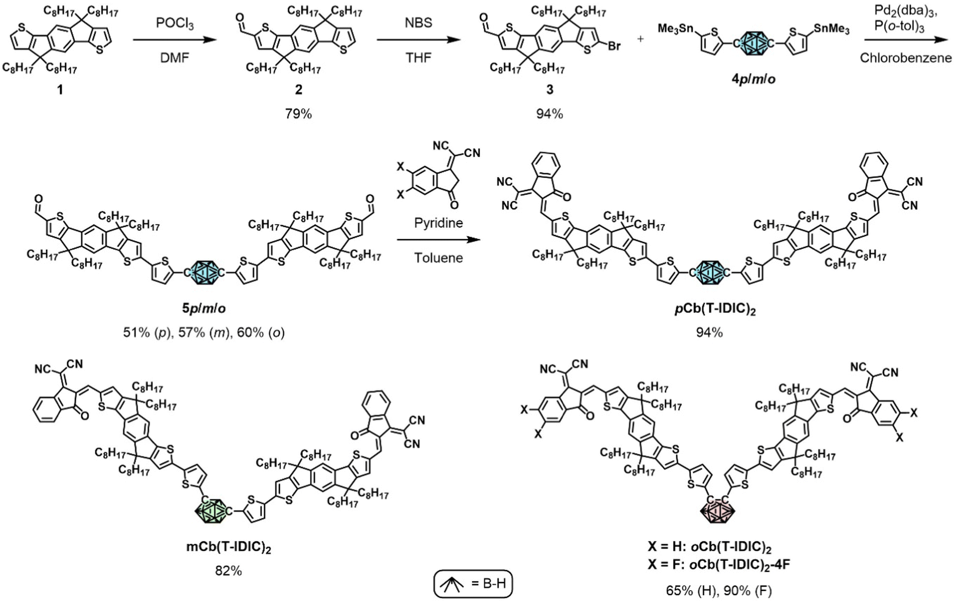 | ||
| Scheme 1 Synthetic routes to the featured NFAs, and their molecular structures. For each NFA, stannylated compounds of the respective carborane isomer (coloured) were used. | ||
The structure of all final compounds was confirmed with a combination of 1H, 11B and 13C NMR spectroscopy, together with mass spectrometry. Thermal gravimetric analyses (TGA) of the resulting species were nearly identical (Fig. S1, ESI†), proving high thermal stabilities, with a 5% loss of mass at Td,5% = 332 °C, and a second degradation step at 411 °C.
Optoelectronic properties
To gain insight into the optical properties of the synthesised materials, absorption and photoluminescence spectroscopy was performed. As seen in Fig. 1a, absorption and emission properties of the four materials exhibited near identical behaviours in dichloromethane solution. As summarised in Table 1, absorption and emission maxima are slightly blue-shifted when progressing from the para to the meta to the ortho species, although they remain within a range of 10 and 15 nm for absorption and emission wavelengths respectively. Fluorination of the ortho species, however, causes a red-shift in absorption of 12 nm, and a red-shift in emission of 13 nm. Time-dependent density functional theory (TD-DFT) reveals that the excitations which give rise to the main absorption peaks of pCb(T-IDIC)2 and mCb(T-IDIC)2 originates from the HOMO → LUMO (75–80%) and HOMO−1 → LUMO+1 (19–24%) transitions (Fig. S2a and b, ESI†). Whilst this excited state makes a significant contribution to the main absorption peak also in oCb(T-IDIC)2 and oCb(T-IDIC)2-4F, the main contribution comes from a different excited state with almost twice the oscillation strength, resulting from HOMO−1 → LUMO (87%) and HOMO → LUMO+1 (12%) transitions (Fig. S2c and d, ESI†). | ||
| Fig. 1 (a) Absorption and emission spectra of NFA solutions in DCM. (b) Cyclic voltammograms of NFAs, scanning at 0.1 V s−1 and using the Fc/Fc+ couple as an internal reference. (c) Frontier molecular orbitals of pCb(T-IDIC)2, as predicted with DFT (B3LYP/6-311G**). | ||
| λ abs,max (nm) | λ abs,ons (nm) | λ PL,max (nm) | Stokes shift (cm−1) | E ½,red (V) | E ½,ox1 (V) | E ½,ox2 (V) | |
|---|---|---|---|---|---|---|---|
| pCb(T-IDIC)2 | 640 | 708 | 737 | 2056 | −1.13 | 0.61 | 1.06 |
| mCb(T-IDIC)2 | 636 | 702 | 733 | 2080 | −1.18 | 0.58 | 1.03 |
| oCb(T-IDIC)2 | 630 | 698 | 722 | 2023 | −1.21 | 0.59 | 1.04 |
| oCb(T-IDIC)2-4F | 642 | 709 | 735 | 1971 | −1.00 | 0.72 | — |
To investigate the electrochemical properties of the materials, cyclic voltammetry (CV) was performed, using the ferrocene/ferrocenium (Fc/Fc+) couple as an internal reference, as depicted in Fig. 1b and summarised in Table 1. Once again, the isomeric differences of the molecular structures did not significantly impact the electochemical properties of the species. p, m, and oCb(T-IDIC)2 all exhibited very similar voltammograms: one reduction peak around −1.17 V, and two reversible oxidation peaks around 0.59 and 1.04 V. Fluorination of oCb(T-IDIC)2, however, resulted in a shift of the reduction and oxidation peaks towards higher potentials, by up to 0.21 V. The second oxidation peak of oCb(T-IDIC)2-4F was not reversible, and oxidation at high potentials seemed to cause film degradation, and thus the analysis was limited to the first oxidation peak.
Redox potentials acquired through CV are commonly used to estimate the HOMO and LUMO energy levels of organic semiconductors, using Fc/Fc+ = 4.8 V as an electrochemical reference. As seen in Table 2, HOMO and LUMO levels are estimated around −5.39 and −3.63 eV for p, m, and oCb(T-IDIC)2. oCb(T-IDIC)2-4F FMOs are estimated at slightly lower at −5.52 and −3.80 eV, reflecting the very high electronegativity of the fluorine atoms. It can also be seen that the energy differences between the estimated HOMOs and LUMOs correspond very well to the optical bandgap, as obtained from the absorption onset, at around 1.76 eV. The general trend is a very slight bandgap increase when moving from the para to the meta to the ortho isomer. The fluorinated oCb(T-IDIC)2-4F slightly narrows the bandgap, as was also indicated by a red-shift in the absorption spectrum compared to its non-fluorinated equivalent oCb(T-IDIC)2.
| HOMO (eV) | LUMO (eV) | E g (eV) | |||||
|---|---|---|---|---|---|---|---|
| CV | DFT | CV | DFT | CV | DFT | UV-Vis | |
| pCb(T-IDIC)2 | −5.41 | −5.58 | −3.67 | −3.36 | 1.74 | 2.22 | 1.75 |
| mCb(T-IDIC)2 | −5.38 | −5.62 | −3.62 | −3.38 | 1.76 | 2.24 | 1.77 |
| oCb(T-IDIC)2 | −5.39 | −5.73 | −3.59 | −3.45 | 1.80 | 2.28 | 1.78 |
| oCb(T-IDIC)2-4F | −5.52 | −5.84 | −3.80 | −3.61 | 1.72 | 2.23 | 1.75 |
Density functional theory (DFT) optimisation was used to predict the structure of the synthesised NFAs, as well as the electron density of their respective HOMOs and LUMOs, as depicted in Fig. 1c and Fig. S3 (ESI†). As is typical for A–D–A type NFAs, and by extension A–D–A′–D–A NFAs, the HOMO was primarily located on the electron-rich IDT moiety, whilst the LUMO was mainly located around the electron-deficient INCN moiety. Notably, no electron density was observed around the carborane moiety in either FMO. Whilst this is typical for p- and m-carborane species, it stands in contrast to many previously reported aryl substituted o-carborane species, where intramolecular charge transfer (ICT) may result in a significant portion of the LUMO being located on the carborane cage.69,70 Such a mechanism is typically accompanied by AIE behaviour, which was not observed for any of the NFAs presented herein. A plausible explanation for the absence of ICT is the presence of the strongly electron withdrawing INCN end-groups preventing electron transfer to the carborane cage. Accordingly, DFT calculations predict a partial ICT between the IDT and INCN moieties instead, as mentioned above. This is similar to previous observations where strongly electron withdrawing moieties are present in the conjugated backbone.41
Overall, DFT calculations predict deeper HOMOs and shallower LUMOs compared to estimates derived from CV (Table 2), resulting in considerably wider bandgaps around 2.24 eV. Once again, this behaviour has been observed in the past, and a common explanation for this discrepancy is the solvation effect in electrochemical measurements, whilst DFT calculations typically refer to a single isolated species in vacuum.71
Morphology comparison of isomers
To investigate how isomer variation impacts thin-film morphology, atomic force microscopy (AFM) was employed. Fig. 2a displays the resulting surface topography images of p, m, and oCb(T-IDIC)2. As can be seen, film surfaces of pristine NFAs were homogenous and overall featureless, with no noticeable differences between materials. All films were smooth with low root mean square (RMS) roughness values within proximity of each other (0.203–0.225 nm). On the other hand, films deposited from 1![[thin space (1/6-em)]](https://www.rsc.org/images/entities/char_2009.gif) :1 (weight) blends with the conjugated polymer PBDB-T exhibited rougher surfaces (RMS = 2.35–2.38) with a fibrous appearance, likely as a result of the polymeric structure as previously noted.72 Again, no obvious difference between NFA isomers could be identified.
:1 (weight) blends with the conjugated polymer PBDB-T exhibited rougher surfaces (RMS = 2.35–2.38) with a fibrous appearance, likely as a result of the polymeric structure as previously noted.72 Again, no obvious difference between NFA isomers could be identified.
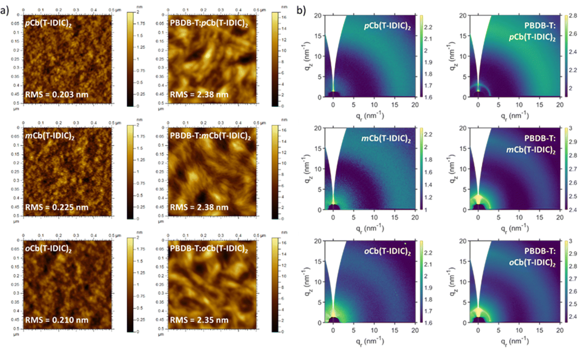 | ||
| Fig. 2 (a) AFM images and (b) GIWAXS scans of pristine and polymer blend thin-films of NFAs featuring each of the three carborane isomers. | ||
Grazing-incidence wide-angle X-ray scattering (GIWAXS) of the same films was also carried out, to investigate the existence of ordered structures within the films. As shown in Fig. 2b, 2D diffractograms of films of pristine NFAs and polymer blends exhibited largely amorphous structures. The use of different isomers did not induce any noticeable change between film morphologies. Polymer blends gave rise to a peak at q = 2.95 nm−1, which is assigned to the (100) lamellar stacking of the polymer.72 This peak was enhanced upon annealing at 100 °C for 10 minutes, particularly in the ortho blend where the peak was absent prior to annealing (Fig. S4, ESI†). The amorphous morphology of pristine NFAs was further confirmed through differential scanning calorimetry (DSC), with an absence of thermal transitions between 25 and 280 °C in all materials, as depicted in Fig. S5 (ESI†).
Device performance
To test the suitability of our materials as electron acceptors in OPVs, devices were fabricated using an inverted architecture, as illustrated in Fig. 3a. The inverted architecture was based on ITO/ZnO/polymer:NFA/MoOx/Ag, where PBDB-T was chosen as the electron donor polymer, given its well matched energy levels and success with similar materials in the past.62,66 | ||
| Fig. 3 (a) Illustration of the OPV device configuration (not to scale). (b) J–V curves of fabricated devices. (c) Energy diagram, comparing FMO levels of the donor polymer with the featured NFAs. | ||
The current–voltage (J–V) characteristics of devices under AM 1.5G illumination are shown in Fig. 3b, and device performance parameters are summarised in Table 3. It is clearly apparent that the choice of carborane isomer in the NFA has a major impact on device efficiency. Whilst devices made from pCb(T-IDIC)2 had an average PCE of 1.93%, and mCb(T-IDIC)2 had slightly higher 2.22%, oCb(T-IDIC)2 had considerably higher 3.00%. The performance of all three materials are in line with or higher than those previously reported for carborane-containing materials, verifying that molecular acceptors are a useful strategy in the synthesis of carborane-containing OPV materials.40,41 Nevertheless, the overall performance of these materials remains modest compared to other non-carborane IDT-INCN flanked materials reported to date.62–67 Although the open-circuit current (VOC) values of the devices were high at around 0.93 V, the short-circuit current density (JSC) remained relatively low, ranging from 5.36 to 7.40 mAcm−2, and J–V curves exhibited non-ideal behaviours with fill factors between 37 and 43%.
| V OC (V) | J SC (mA cm−2) | FF | PCE (%) | |
|---|---|---|---|---|
| pCb(T-IDIC)2 | 0.93 | 5.36 | 0.39 | 1.93 |
| mCb(T-IDIC)2 | 0.92 | 6.48 | 0.37 | 2.22 |
| oCb(T-IDIC)2 | 0.95 | 7.40 | 0.43 | 3.00 |
| oCb(T-IDIC)2-4F | 0.92 | 10.27 | 0.54 | 5.07 |
High-performing OPVs require a sufficient energetic offset between donor and acceptor FMOs to promote exciton-to-charge separation, resulting in charge transfer from one material to the other. The energy diagram in Fig. 3c illustrates the offset between the reported LUMO of PBDB-T versus p, m, and oCb(T-IDIC)2, which allows for efficient exciton splitting.73 Meanwhile, the offset between HOMOs is much narrower, with HOMOs of all three isomers being located around −5.39 eV. Increasing the offset by lowering the HOMO of the NFA is therefore a natural progression towards a higher JSC.74 Fluorination is an approach which has previously been used to lower the FMOs of similar IDT-INCN flanked A–D–A′–D–A materials, generally with great success in increasing JSC.62,66 With that in mind, we synthesised a fluorinated version of the highest performing isomer, namely oCb(T-IDIC)2-4F. As discussed in Section 2.2, this resulted in deeper energies of both the HOMO and the LUMO, resulting in larger energy offsets with respect to the polymer. This had the desired effect of increasing JSC from 7.40 to 10.27 mA cm−2, and the corresponding EQE is shown in Fig. S6 (ESI†). It is possible that JSC could be improved further by combining donor and acceptor materials with a lesser spectral overlap (Fig. S7, ESI†).
In addition to increased JSC, fluorination also improved the FF from 43 to 54%. To understand this change, charge carrier mobilities (μ) of the NFA blends were derived by the space charge limited current (SCLC) method.75J–V characteristics of single-carrier SCLC devices are depicted in Fig. S8 and S9 (ESI†) and mobilities are shown in Table S1 (ESI†). The hole mobilities of the blends are dominated by the p-type PBDB-T, with values in the order of 10−5 cm2 V−1 s−1. Meanwhile, electron-only SCLC devices revealed a much higher electron mobility of the blend with oCb(T-IDIC)2-4F at 6 × 10⁻⁷ cm2 V−1 s−1, compared to non-fluorinated NFAs in the region 1–2 × 10⁻⁷ cm2 V−1 s−1. This resulted in a more favourable μe/μh ratio and thus a higher FF.76 As a consequence, the overall PCE was measured at 5.07% which, to the best of our knowledge, is the highest PCE reported for carborane-containing OPVs, and is more than double the best values previously reported.
Conclusions
In summary, we have synthesised four novel carborane-centred NFAs in an A–D–A′–D–A fashion. DFT calculations show that the carborane moieties do not participate in the π-conjugation, however, as HOMOs are located primarily on the IDT moieties, and LUMOs on the INCN moieties. Furthermore, we successfully fabricated OPV devices using PBDB-T:NFA blends, proving their applicability in OPV technology. The use of different carborane isomers (para, meta, and ortho) had a very limited effect on the optoelectronic properties of the materials, and no difference between isomers could be observed in thin-film morphology. On the other hand, the choice of isomer had a drastic impact on OPV performance, with the ortho isomer demonstrating superior device characteristics. To further increase the FMO offsets between the polymer donor and the NFA, a fluorinated version of the ortho isomer was synthesised. This increased the PCE from 3.00 to 5.07%, thus reporting the highest OPV efficiencies of carborane-containing OPV materials to date. Overall, our results demonstrate that carborane-containing materials can be utilised as electron acceptors in bulk heterojunction blends, and further highlight the viability of A–D–A′–D–A design strategies for such materials.Author contributions
Filip Aniés (conceptualisation, investigation, project administration, visualisation, writing – original draft), Francesco Furlan (investigation, visualisation, writing – review & editing), Zhuoran Qiao (investigation, visualisation), Valentina Pirela (investigation, visualisation), Matthew Bidwell (investigation), Martina Rimmele (investigation), Jaime Martín (supervision), Nicola Gasparini (resources, supervision, writing – review & editing), Martin Heeney (conceptualisation, resources, supervision, writing – review & editing).Conflicts of interest
There are no conflicts to declare.Acknowledgements
We thank the Engineering and Physics Science Research Council (EPSRC) (EP/V048686/1 and EP/T028513/1) and the Royal Society and Wolfson Foundation for financial support. F. A. acknowledges the Wilkinson Charitable Foundation for financial support. This work was supported by King Abdullah University of Science and Technology (KAUST) Office of Sponsored Research (OSR) under award OSR-2019-CRG8-4095.Notes and references
- R. N. Grimes, Carboranes, Academic Press, 3rd edn, 2016 Search PubMed.
- S.-Y. Lu and I. Hamerton, Prog. Polym. Sci., 2002, 27, 1661–1712 CrossRef CAS.
- R. Núñez, I. Romero, F. Teixidor and C. Viñas, Chem. Soc. Rev., 2016, 45, 5147–5173 RSC.
- R. Núñez, M. Tarrés, A. Ferrer-Ugalde, F. F. de Biani and F. Teixidor, Chem. Rev., 2016, 116, 14307–14378 CrossRef PubMed.
- Z. Chang, N. C. Okoye, M. J. Urffer, A. D. Green, K. E. Childs and L. F. Miller, Nucl. Instrum. Methods Phys. Res., Sect. A, 2015, 769, 112–122 CrossRef CAS.
- D. Emin and T. L. Aselage, J. Appl. Phys., 2005, 97, 013529 CrossRef.
- A. Pitto-Barry, Polym. Chem., 2021, 12, 2035–2044 RSC.
- A. Marfavi, P. Kavianpour and L. M. Rendina, Nat. Rev. Chem., 2022, 6, 486–504 CrossRef.
- P. Stockmann, M. Gozzi, R. Kuhnert, M. B. Sárosi and E. Hey-Hawkins, Chem. Soc. Rev., 2019, 48, 3497–3512 RSC.
- J. Ochi, K. Tanaka and Y. Chujo, Angew. Chem., Int. Ed., 2020, 59, 9841–9855 CrossRef CAS PubMed.
- A. V. Marsh, N. J. Cheetham, M. Little, M. Dyson, A. J. P. White, P. Beavis, C. N. Warriner, A. C. Swain, P. N. Stavrinou and M. Heeney, Angew. Chem., Int. Ed., 2018, 57, 10640–10645 CrossRef CAS PubMed.
- A. V. Marsh, M. J. Dyson, N. J. Cheetham, M. Bidwell, M. Little, A. J. P. White, C. N. Warriner, A. C. Swain, I. McCulloch, P. N. Stavrinou, S. C. J. Meskers and M. Heeney, Adv. Electron. Mater., 2020, 6, 2000312 CrossRef CAS.
- A. V. Marsh, M. Little, N. J. Cheetham, M. J. Dyson, M. Bidwell, A. J. P. White, C. N. Warriner, A. C. Swain, I. McCulloch, P. N. Stavrinou and M. Heeney, Chem. – Eur. J., 2021, 27, 1970–1975 CrossRef CAS PubMed.
- K.-R. Wee, Y.-J. Cho, J. K. Song and S. O. Kang, Angew. Chem., Int. Ed., 2013, 52, 9682–9685 CrossRef CAS PubMed.
- H. Naito, K. Nishino, Y. Morisaki, K. Tanaka and Y. Chujo, Angew. Chem., Int. Ed., 2017, 56, 254–259 CrossRef CAS PubMed.
- K.-R. Wee, W.-S. Han, D. W. Cho, S. Kwon, C. Pac and S. O. Kang, Angew. Chem., Int. Ed., 2012, 51, 2677–2680 CrossRef CAS PubMed.
- K. Tanaka, M. Gon, S. Ito, J. Ochi and Y. Chujo, Coord. Chem. Rev., 2022, 472, 214779 CrossRef CAS.
- K. Kokado and Y. Chujo, J. Org. Chem., 2011, 76, 316–319 CrossRef CAS PubMed.
- M. Zhu, Q. Zhou, H. Cheng, Z. Meng, L. Xiang, Y. Sha, H. Yan and X. Li, New J. Chem., 2022, 46, 11382–11388 RSC.
- H. Naito, Y. Morisaki and Y. Chujo, Angew. Chem., Int. Ed., 2015, 54, 5084–5087 CrossRef CAS PubMed.
- J. Li, C. Yang, X. Peng, Y. Chen, Q. Qi, X. Luo, W.-Y. Lai and W. Huang, J. Mater. Chem. C, 2018, 6, 19–28 RSC.
- Y. Cho, S. Kim, J. Lee, W. Han, C. H. Kim, H. Son and S. O. Kang, Chem. – Eur. J., 2019, 25, 8149–8156 CrossRef CAS PubMed.
- X. Wu, J. Guo, Y. Cao, J. Zhao, W. Jia, Y. Chen and D. Jia, Chem. Sci., 2018, 9, 5270–5277 RSC.
- J. J. Peterson, A. R. Davis, M. Werre, E. B. Coughlin and K. R. Carter, ACS Appl. Mater. Interfaces, 2011, 3, 1796–1799 CrossRef CAS PubMed.
- R. Huang, H. Liu, K. Liu, G. Wang, Q. Liu, Z. Wang, T. Liu, R. Miao, H. Peng and Y. Fang, Anal. Chem., 2019, 91, 14451–14457 CrossRef CAS PubMed.
- C. Li, M. P. Aldred, R. A. Harder, Y. Chen, D. S. Yufit, M.-Q. Zhu and M. A. Fox, Chem. Commun., 2021, 57, 9466–9469 RSC.
- L. Böhling, A. Brockhinke, J. Kahlert, L. Weber, R. A. Harder, D. S. Yufit, J. A. K. Howard, J. A. H. MacBride and M. A. Fox, Eur. J. Inorg. Chem., 2016, 403–412 CrossRef.
- K.-R. Wee, Y.-J. Cho, S. Jeong, S. Kwon, J.-D. Lee, I.-H. Suh and S. O. Kang, J. Am. Chem. Soc., 2012, 134, 17982–17990 CrossRef CAS PubMed.
- R. Furue, T. Nishimoto, I. S. Park, J. Lee and T. Yasuda, Angew. Chem., Int. Ed., 2016, 55, 7171–7175 CrossRef CAS PubMed.
- A. R. Davis, J. J. Peterson and K. R. Carter, ACS Macro Lett., 2012, 1, 469–472 CrossRef CAS PubMed.
- Y. Kim, S. Park, Y. H. Lee, J. Jung, S. Yoo and M. H. Lee, Inorg. Chem., 2016, 55, 909–917 CrossRef CAS PubMed.
- Q. Li, C. Shi, M. Huang, X. Zhang, F. Sun, Y. Zheng, H. Yan, C. Yang and A. Yuan, Dalton Trans., 2021, 50, 16304–16310 RSC.
- K. Kokado and Y. Chujo, Macromolecules, 2009, 42, 1418–1420 CrossRef CAS.
- K. Kokado, Y. Tokoro and Y. Chujo, Macromolecules, 2009, 42, 9238–9242 CrossRef CAS.
- M. Tominaga, Y. Morisaki, H. Naito and Y. Chujo, Polym. J., 2014, 46, 740–744 CrossRef CAS.
- K. Kokado, Y. Tokoro and Y. Chujo, Macromolecules, 2009, 42, 2925–2930 CrossRef CAS.
- K. Kokado, M. Tominaga and Y. Chujo, Macromol. Rapid Commun., 2010, 31, 1389–1394 CrossRef CAS PubMed.
- J. Marshall, Z. Fei, C. P. Yau, N. Yaacobi-Gross, S. Rossbauer, T. D. Anthopoulos, S. E. Watkins, P. Beavis and M. Heeney, J. Mater. Chem. C, 2014, 2, 232–239 RSC.
- J. Marshall, B. C. Schroeder, H. Bronstein, I. Meager, S. Rossbauer, N. Yaacobi-Gross, E. Buchaca-Domingo, T. D. Anthopoulos, N. Stingelin, P. Beavis and M. Heeney, Macromolecules, 2014, 47, 89–96 CrossRef CAS.
- J. Marshall, J. Hooton, Y. Han, A. Creamer, R. S. Ashraf, Y. Porte, T. D. Anthopoulos, P. N. Stavrinou, M. A. McLachlan, H. Bronstein, P. Beavis and M. Heeney, Polym. Chem., 2014, 5, 6190–6199 RSC.
- F. Aniés, Z. Qiao, M. I. Nugraha, A. Basu, T. D. Anthopoulos, N. Gasparini and M. Heeney, Polymer, 2022, 240, 124481 CrossRef.
- B. Fabre, S. Chayer and M. G. H. Vicente, Electrochem. Commun., 2003, 5, 431–434 CrossRef CAS.
- Y. C. Simon, J. J. Peterson, C. Mangold, K. R. Carter and E. B. Coughlin, Macromolecules, 2009, 42, 512–516 CrossRef CAS.
- I. Nar, A. Atsay, A. Altındal and E. Hamuryudan, Inorg. Chem., 2018, 57, 2199–2208 CrossRef CAS PubMed.
- F. Ye, S. Zhang, J. Warby, J. Wu, E. Gutierrez-Partida, F. Lang, S. Shah, E. Saglamkaya, B. Sun, F. Zu, S. Shoaee, H. Wang, B. Stiller, D. Neher, W.-H. Zhu, M. Stolterfoht and Y. Wu, Nat. Commun., 2022, 13, 7454 CrossRef CAS PubMed.
- B. G. Kim, W. Jang, H. Jeon, S. Lee, W.-S. Han and D. H. Wang, Sol. Energy Mater. Sol. Cells, 2020, 208, 110414 CrossRef CAS.
- A. M. Spokoyny, T. C. Li, O. K. Farha, C. W. Machan, C. She, C. L. Stern, T. J. Marks, J. T. Hupp and C. A. Mirkin, Angew. Chem., Int. Ed., 2010, 49, 5339–5343 CrossRef CAS PubMed.
- T. C. Li, A. M. Spokoyny, C. She, O. K. Farha, C. A. Mirkin, T. J. Marks and J. T. Hupp, J. Am. Chem. Soc., 2010, 132, 4580–4582 CrossRef CAS PubMed.
- S. Şener, Heterocycl. Commun., 2020, 26, 37–45 Search PubMed.
- Q. He, P. Kafourou, X. Hu and M. Heeney, SN Appl. Sci., 2022, 4, 247 CrossRef CAS.
- A. Wadsworth, M. Moser, A. Marks, M. S. Little, N. Gasparini, C. J. Brabec, D. Baran and I. McCulloch, Chem. Soc. Rev., 2019, 48, 1596–1625 RSC.
- G. Zhang, F. R. Lin, F. Qi, T. Heumüller, A. Distler, H.-J. Egelhaaf, N. Li, P. C. Y. Chow, C. J. Brabec, A. K.-Y. Jen and H.-L. Yip, Chem. Rev., 2022, 122, 14180–14274 CrossRef CAS PubMed.
- Z. Zhang, J. Yuan, Q. Wei and Y. Zou, Front. Chem., 2018, 6, 414 CrossRef PubMed.
- G. Zhang, J. Zhao, P. C. Y. Chow, K. Jiang, J. Zhang, Z. Zhu, J. Zhang, F. Huang and H. Yan, Chem. Rev., 2018, 118, 3447–3507 CrossRef CAS PubMed.
- W. Zhang, J. Smith, S. E. Watkins, R. Gysel, M. McGehee, A. Salleo, J. Kirkpatrick, S. Ashraf, T. Anthopoulos, M. Heeney and I. McCulloch, J. Am. Chem. Soc., 2010, 132, 11437–11439 CrossRef CAS PubMed.
- S. Holliday, R. S. Ashraf, A. Wadsworth, D. Baran, S. A. Yousaf, C. B. Nielsen, C.-H. Tan, S. D. Dimitrov, Z. Shang, N. Gasparini, M. Alamoudi, F. Laquai, C. J. Brabec, A. Salleo, J. R. Durrant and I. McCulloch, Nat. Commun., 2016, 7, 11585 CrossRef CAS PubMed.
- Z. Fei, F. D. Eisner, X. Jiao, M. Azzouzi, J. A. Röhr, Y. Han, M. Shahid, A. S. R. Chesman, C. D. Easton, C. R. McNeill, T. D. Anthopoulos, J. Nelson and M. Heeney, Adv. Mater., 2018, 30, 1705209 CrossRef PubMed.
- Y. Lin, Q. He, F. Zhao, L. Huo, J. Mai, X. Lu, C.-J. Su, T. Li, J. Wang, J. Zhu, Y. Sun, C. Wang and X. Zhan, J. Am. Chem. Soc., 2016, 138, 2973–2976 CrossRef CAS PubMed.
- Y. Lin, J. Wang, Z.-G. Zhang, H. Bai, Y. Li, D. Zhu and X. Zhan, Adv. Mater., 2015, 27, 1170–1174 CrossRef CAS PubMed.
- Y. Wu, H. Bai, Z. Wang, P. Cheng, S. Zhu, Y. Wang, W. Ma and X. Zhan, Energy Environ. Sci., 2015, 8, 3215–3221 RSC.
- Y. Lin, Z.-G. Zhang, H. Bai, J. Wang, Y. Yao, Y. Li, D. Zhu and X. Zhan, Energy Environ. Sci., 2015, 8, 610–616 RSC.
- H. S. Kim, S. Rasool, W. S. Shin, C. E. Song and D.-H. Hwang, ACS Appl. Mater. Interfaces, 2020, 12, 50638–50647 CrossRef CAS PubMed.
- X. Chen, Y. Luo, M. Lv, C. Yi, M. Yin, S. Liu, Z. Xiao and L. Ding, Mater. Chem. Front., 2022, 6, 802–806 RSC.
- G. Cai, Z. Chen, M. Li, Y. Li, P. Xue, Q. Cao, W. Chi, H. Liu, X. Xia, Q. An, Z. Tang, H. Zhu, X. Zhan and X. Lu, Adv. Sci., 2022, 9, 2103428 CrossRef CAS PubMed.
- M. J. Cho, G. E. Park, S. Y. Park, Y.-U. Kim and D. H. Choi, RSC Adv., 2017, 7, 38773–38779 RSC.
- J. Zhu, X. Zheng, H. Tan, H. Tan, J. Yang, J. Yu and W. Zhu, Chem. Phys. Lett., 2019, 726, 7–12 CrossRef CAS.
- F. Zhang, X. Yu, M. Xiong, Z. Yin, Y. Wang, J. Yu, J. Cao, H. Tan and M. Zhang, Synth. Met., 2021, 278, 116838 CrossRef CAS.
- D. F. Zeigler, K.-S. Chen, H.-L. Yip, Y. Zhang and A. K.-Y. Jen, J. Polym. Sci., Part A: Polym. Chem., 2012, 50, 1362–1373 CrossRef CAS.
- H. Yamamoto, J. Ochi, K. Yuhara, K. Tanaka and Y. Chujo, Cell Rep. Phys. Sci., 2022, 3, 100758 CrossRef CAS.
- S. Kwon, K.-R. Wee, Y.-J. Cho and S. O. Kang, Chem. – Eur. J., 2014, 20, 5953–5960 CrossRef CAS PubMed.
- J. Sworakowski, J. Lipiński and K. Janus, Org. Electron., 2016, 33, 300–310 CrossRef CAS.
- D. Qian, L. Ye, M. Zhang, Y. Liang, L. Li, Y. Huang, X. Guo, S. Zhang, Z. Tan and J. Hou, Macromolecules, 2012, 45, 9611–9617 CrossRef CAS.
- J. Bertrandie, J. Han, C. S. P. De Castro, E. Yengel, J. Gorenflot, T. Anthopoulos, F. Laquai, A. Sharma and D. Baran, Adv. Mater., 2022, 2202575 CrossRef CAS PubMed.
- S. Karuthedath, J. Gorenflot, Y. Firdaus, N. Chaturvedi, C. S. P. De Castro, G. T. Harrison, J. I. Khan, A. Markina, A. H. Balawi, T. A. Dela Peña, W. Liu, R.-Z. Liang, A. Sharma, S. H. K. Paleti, W. Zhang, Y. Lin, E. Alarousu, S. Lopatin, D. H. Anjum, P. M. Beaujuge, S. De Wolf, I. McCulloch, T. D. Anthopoulos, D. Baran, D. Andrienko and F. Laquai, Nat. Mater., 2021, 20, 378–384 CrossRef CAS PubMed.
- P. W. M. Blom, M. J. M. de Jong and M. G. van Munster, Phys. Rev. B: Condens. Matter Mater. Phys., 1997, 55, R656–R659 CrossRef CAS.
- L. J. A. Koster, V. D. Mihailetchi and P. W. M. Blom, Appl. Phys. Lett., 2006, 88, 052104 CrossRef.
Footnote |
| † Electronic supplementary information (ESI) available: Supporting figures and data, full methodology. See DOI: https://doi.org/10.1039/d2tc05018h |
| This journal is © The Royal Society of Chemistry 2023 |