DOI:
10.1039/D2TC04215K
(Paper)
J. Mater. Chem. C, 2023,
11, 8146-8153
Organic ammonium iodide salts as passivation for buried interface enables efficient and stable NiOx based p-i-n perovskite solar cells†
Received
4th October 2022
, Accepted 28th December 2022
First published on 29th December 2022
Abstract
The interfaces between a halide perovskite absorber film and its charge transporting layers have been identified as one of the key bottlenecks for achieving high performance and stability. Herein we report a benzothieno[3,2-b]benzothiophene (BTBT) derivative and a carbazole derivative to passivate the interface between the sputtered NiOx and the halide perovskite in p-i-n perovskite solar cells (PSCs). The treatment of the NiOx with the BTBT derivative significantly enhances the open-circuit voltage (Voc), boosting the champion power conversion efficiency (PCE) from 16.6% to 18.6%. We carry out an in-depth analysis of the interface employing a lift-off procedure revealing that the BTBT molecules reside at the bottom interface and successfully suppress a (redox) reaction at this interface. As a result of the improved interface quality, the stability of the PSCs is superior under maximum power point (MPP) conditions and in ambient conditions, retaining 89% of the initial PCE after 250 hours at 25% relative humidity and 95% after 1 hour under continuous MPP tracking (MPPT).
10th Anniversary Statement
Over the past ten years, the Journal of Materials Chemistry C has continued along the path of the Journal of Materials Chemistry as a prime destination for studies that combine fundamental advances in materials chemistry with device aspects. This also holds for the hybrid perovskite field, with many inspiring and impactful papers being published in the journal. The topic of the current manuscript, interfacial engineering of perovskite solar cells, has received significant attention over the past years. With the current manuscript, we show that designed large organic ammonium cations can be employed as interlayers at the hole-transporting layer/perovskite interface to enhance the power conversion efficiency (PCE) and stability of inverted architecture perovskite solar cells (PSCs). While inverted architecture PSCs generally reach lower PCEs than their regular architecture counterparts, we are convinced that interfacial engineering can greatly reduce this gap and that designed large organic molecules possess significant potential as interlayer materials.
|
1. Introduction
Perovskite solar cells have emerged as a promising photovoltaic technology because of their excellent performance and the possibility to be processed at a low cost. Over a decade of intense research on PSCs has led the power conversion efficiency (PCE) to reach a certified 25.7% and 31.3% for single junction and perovskite/silicon (Si) tandem solar cells, respectively.1 Despite the high performance, multiple bottlenecks need to be overcome towards the commercialization of PSCs. Firstly, as PSCs are mainly solution-processed devices, the performance is still significantly inferior on a larger scale compared to other photovoltaic (PV) technologies. Secondly, the perovskite material has the tendency to degrade in outdoor conditions, such as high temperatures, UV exposure, and ambient atmosphere.2,3 Consequently, the high initial performance declines rather quickly over time in normal operating conditions. Many approaches are being investigated to improve the stability of PSCs, such as compositional3 and interfacial engineering4,5 of the perovskite layer, development of more stable transport layers, and process engineering of all the layers.6
Typically, PSCs are fabricated in one of two architectures, viz. n-i-p and p-i-n (inverted). In the n-i-p configuration, the electron transporting layer (ETL) is processed first, followed by the perovskite layer and the hole transporting layer (HTL). Whereas in p-i-n, the HTL is processed first, followed by the perovskite layer and the ETL. The majority of the research has been conducted on n-i-p cells, and the highest PCEs have also been obtained in this architecture. However, these n-i-p cells frequently use TiO2 as ETL, which is prone to induce degradation under UV light,7 and they generally employ doped organic semiconductors as HTL, such as spiro-OMeTAD, which are unstable at high temperatures8 or polymers like poly(triaryl)amine (PTAA) which are costly, suffer from batch to batch variation and need to be doped with hygroscopic dopants. Therefore, research attention has lately been shifting to p-i-n cells since they are generally more stable and can employ cheap transport materials such as inorganic metal oxides (e.g., NiOx), which can be deposited as HTL in this configuration. Additionally, these inorganic materials can be processed with large-scale compatible deposition techniques such as sputtering9 and thermal evaporation. Nevertheless, the PCE of p-i-n PSCs is still lagging compared to n-i-p PSCs, certainly in the case when sputtered NiOx10–12 is employed as HTL, where mainly the inferior open-circuit voltage, Voc, is at the origin of the lower PCE.12 It is argued that the lower Voc for NiOx-based HTLs originates from an inferior energy band alignment of the valence band maxima relative to the perovskite layer. Therefore, doping of the solution-processed NiOx layer with Li, Mg, and Cu has been an approach to improve the alignment.13,14 However, Caleb et al.12 showed the formation of a hole blocking PbI2−xBrx layer at the NiOx/perovskite interface due to redox reactions. Excess formamidinium iodide (FAI) in the halide perovskite precursor was employed, which suppressed the formation of the hole blocking PbI2−xBrx, resulting in a significantly enhanced Voc, close to the Voc when PTAA is used as HTL. Liu et al.,15 introduced phenethylammonium iodide (PEAI) to modify the NiOx/perovskite interface, which simultaneously contributed to enhanced crystallinity and stability of the halide perovskite layer, passivating interface defects, forming a two-dimensional PEA2PbI4 perovskite layer, and superior interface contact properties. Other organic molecules, such as guanidinium (Gua), ethylammonium (EA), n-butylammonium (BA) and dimethylammonium (DEA) have also been employed at the HTL/perovskite interface and it was found that the binding affinity of the molecules to the substrates is one of the key determinants to form a 2D phase at the buried interface.16 In the work by Chen et al.16 only Gua was able to form a 2D phase (Gua2PbI4) and was therefore used as passivation layer. However, the influence on the photovoltaic performance of PSCs was not shown for the other organic molecules, which don’t seem to form a 2D phase according to the XRD results. Therefore, it is not clear whether the capability of an organic molecule to form a 2D phase at the bottom interface is essential to act as a passivation layer.
In this work, two large organic ammonium iodide salts, a carbazole (Cz) derivative and a benzothieno[3,2-b]benzothiophene (BTBT) derivative are used as an interlayer between sputtered NiOx and halide perovskite, as shown in Fig. 1. The BTBT derivative was recently used by some of the authors to form quasi-2D cesium lead iodide perovskites with significantly enhanced stability compared to butylammonium-based ones.17 In the current work, the potential of this BTBT derivative as a passivator at HTL/perovskite interfaces is evaluated. Photoluminescence quantum yield (PLQY) measurements show that both interlayer materials have the capability to passivate the interfacial defects, with Voc enhancements of 40 mV and 100 mV for the Cz and BTBT interlayers, respectively, compared to the control devices. External quantum efficiency (EQE) measurements reveal that the BTBT interlayer results in a superior charge carrier extraction at the NiOx/perovskite interface compared to the Cz-based one and consequently gives rise to a higher short-circuit current density (Jsc), which is potentially related to the well-known high charge carrier mobility of BTBT derivatives.18–21
 |
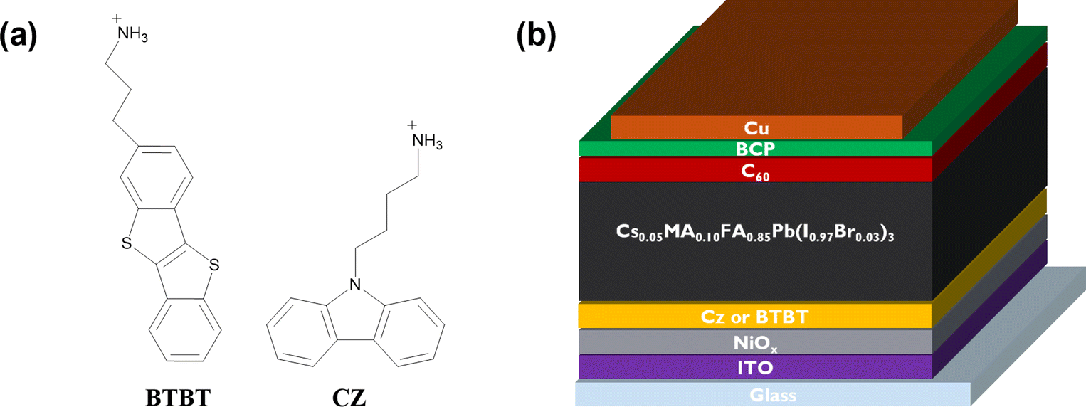
| | Fig. 1 (a) Molecular structure of BTBT and Cz. (b) Perovskite solar cell stack depiction. The control sample does not contain any modification between NiOx and the perovskite layer. | |
2. Results and discussion
The BTBT or Cz ammonium iodide salts were spin-coated from dimethylformamide (DMF) on top of the HTL, followed by a drying step. Next, the 3D halide perovskite was deposited via spin coating and annealed (details are present in the ESI†). The sample without the interlayer is referred to as control, whereas the samples with the carbazole and BTBT-based interlayer are referred to as Cz and BTBT, respectively.
A. PL and TRPL
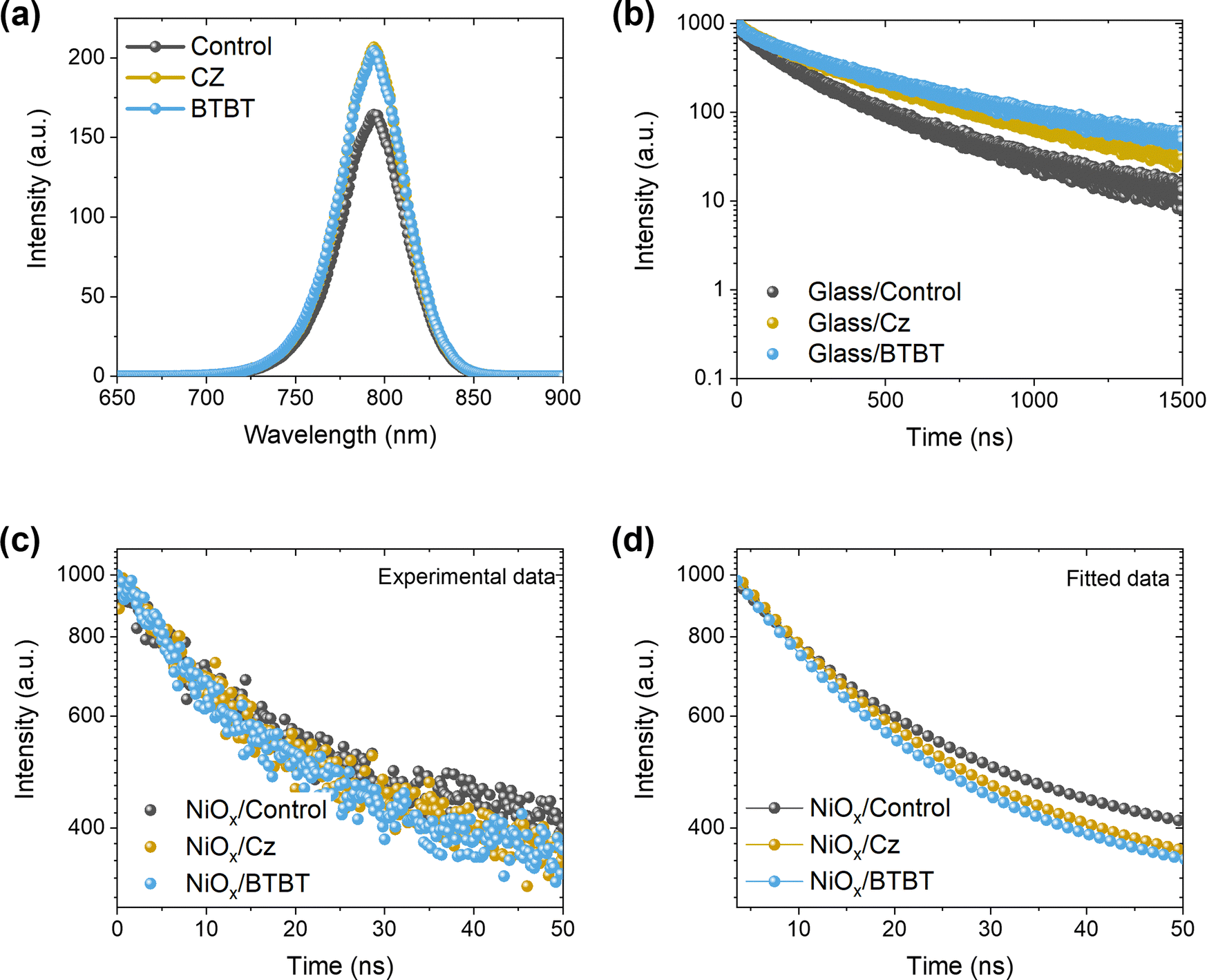
To get insights into the impact of the interlayers on the non-radiative interface recombination and on the hole extraction, we performed steady-state (SSPL) and time-resolved photoluminescence (TRPL) measurements on glass samples with and without HTL (NiOx). As shown in Fig. 2a, the films with both interlayers deposited directly on glass (without HTL) give rise to a very similar SSPL peak which is more intense than for the control film, indicating enhanced radiative recombination by the passivation of interfacial defects. The average lifetime of the carriers, τavg, was extracted from the TRPL data using a biexponential fit:
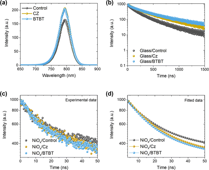 |
| | Fig. 2 (a) Steady-state PL and (b) time-resolved PL measurements for perovskite films on glass, with and without the interlayers. (c and d) Raw and fitted data of time-resolved PL measurements for perovskite films with and without interlayers on the HTL (NiOx). | |
The values for A1, A2, τ1 and τ2 are displayed in the ESI† (Table S1). Based on this fitting, an extended average lifetime of the photo-generated carriers is revealed, going from 196 ns for the control to 285 ns and 317 ns for the Cz and BTBT interlayers, respectively, indicating the suppression of non-radiative recombination with the interlayers. The TRPL measurements conducted on the substrates with NiOx, as shown in Fig. 2c and d, reveal a very slightly accelerated decay in the first tens of ns with both of the interlayers. Such accelerated decay could be either due to enhanced interfacial trap recombination or due to improved hole extraction. Given the improved lifetimes of the photo-generated carriers in the presence of the interlayers, as determined from the measurements on the glass substrates, it is suggested that the faster decay on NiOx is due to improved hole extraction. Nevertheless, the carriers have a very similar lifetimes (13.5–14.5 ns) with and without the interlayers, so the influence of the interlayers on the Jsc of solar cell devices is expected to be rather limited based on these measurements.
B. JV and EQE
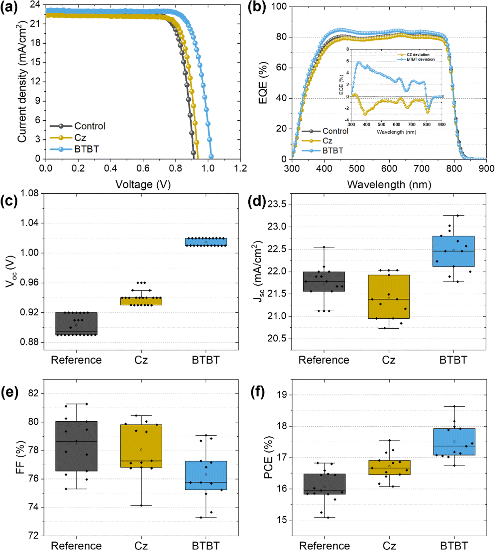
The photovoltaic performance is shown in Fig. 3 and summarized in Table 1. As seen from the JV curves in Fig. 3a, the interlayers mainly have an influence on the Voc, which is to be expected for the passivation of interface defects. The improvement with the BTBT interlayer is quite significant compared to that based on Cz, exceeding the Voc of the control sample (∼0.91 V) with 100 mV compared to 30 mV using Cz. Small differences in Jsc were noticed as well, which are more clearly visualized by the EQE measurements shown in Fig. 3c. The inset figure represents the difference between the EQE signal of the cell with an interlayer and the control cell as a function of wavelength, such that the influence of the interlayers on the EQE at each wavelength is more apparent. As smaller wavelengths are mainly absorbed near the bottom interface of the perovskite film, where these interlayers are present according to HAXPES measurements (discussed in next section), the influence of the interlayers on the EQE signal is expected to be most significant for wavelengths in the range of 300–500 nm. Indeed, Fig. 3b reveals that the BTBT interlayer improves the EQE signal of the control film by approximately 5% (absolute) in the small wavelength region, while the Cz interlayer seems to slightly suppress the signal. This corresponds well with the measured Jsc, with values of 22.65 mA cm−2, 22.43 mA cm−2 and 23.1 mA cm−2 for the control film, Cz interlayer, and BTBT interlayer, respectively. These results suggest that the BTBT interlayer improves the charge carrier extraction at the interface, as was suggested by the TRPL measurements, which may either be the consequence of improved energy level alignment or the well-known superior charge-carrier mobility of BTBT molecules.15,18–20,22 Since a lift-off procedure (vide infra) is only possible with PTAA as a sacrificial layer, PSCs with PTAA as HTL were prepared as well, for which the J–V curves are shown in Fig. S2 (ESI†). For this HTL, an improvement in Voc is achieved as well using both interlayers. In comparison with NiOx as HTL, the improvement with the BTBT interlayer is however more limited and quite similar to that achieved with Cz as the interlayer. This suggests that the influence of the interlayers on the interface with NiOx is more complex than for PTAA and likely related to the redox reactions which can occur at this interface.12 For both HTLs, the champion efficiencies were achieved when using BTBT as an interlayer, achieving 18.6% and 20.6% for NiOx and PTAA, respectively.
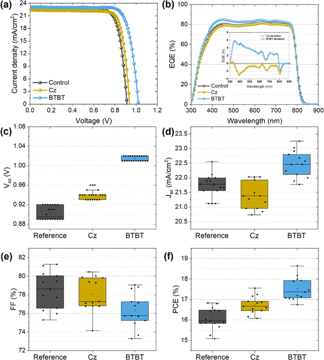 |
| | Fig. 3 (a) JV-curves of the champion PSCs with and without the interlayers and (b) the corresponding EQE output. The statistical distribution of the measured (c–f) Voc, Jsc, FF and PCE. | |
Table 1 Solar cell device parameters extracted from the JV-curves of the champion devices. The average values and deviation for the PCE is noted within the brackets
| Interlayer |
J
sc [mA cm−2] |
V
oc [V] |
FF [%] |
PCE [%] |
| N.A. (Control) |
22.65 |
0.92 |
79.47 |
16.58 (16.0 ± 0.3) |
| Cz |
22.43 |
0.94 |
80.46 |
16.94 (16.6 ± 0.2) |
| BTBT |
23.10 |
1.02 |
79.07 |
18.64 (17.5 ± 0.4) |
C. XRD, XPS and HAXPES
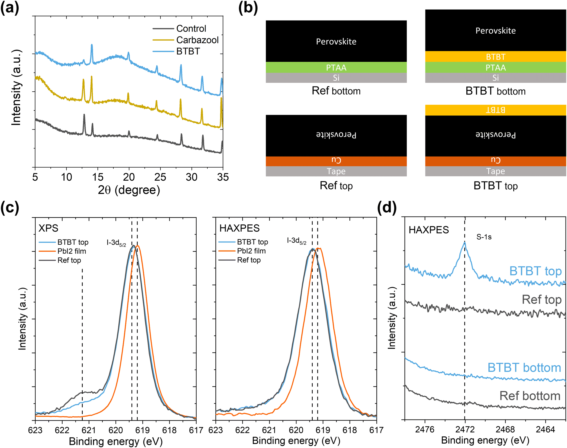
To gain more insight into the interlayer formation, an analysis method is required which can probe this buried interface. As surface-sensitive techniques like XPS are not suitable in the normal solar cell configuration, a lift-off process23 is applied (peeling off the perovskite film from its original substrate and attaching it in reverse orientation to a new substrate, as illustrated in Fig. S1, ESI†). The main requirement for this approach is the use of an (HTL) material that can be dissolved in a perovskite-compatible solvent. Unfortunately, the preferred HTL, NiOx, does not allow for the use of such an approach, meaning that an alternative HTL like PTAA, which is usually dissolved in chlorobenzene or toluene, has to be used for this purpose.23,24 The lift-off process is described in more detail in the ESI† (Fig. S1).
XRD measurements on the lift-off samples (Fig. 4a) do not reveal the formation of 2D halide perovskites, as no reflections are observed at angles below 10°. However, it is clear that the presence of the interlayers results in different ratios of the main perovskite reflection at ∼14° 2θ and the main PbI2 reflection at 12.8° 2θ. For the control film without interlayer, the main PbI2 reflection is more intense than the main perovskite reflection, suggesting that the PbI2 content is mainly present at the HTL/perovskite interface in the inverted cell configuration. With the Cz interlayer, the two reflections are of a similar magnitude, while for the BTBT interlayer, the intensity of the PbI2 reflection is significantly diminished. However, it is not clear whether the PbI2 content is present at the interface or in the bulk. In case the PbI2 content would be concentrated at the interface, the XRD results could, at least in part, explain the superior performance of the BTBT interlayer since PbI2 is known to act as a hole blocking layer.11 To verify whether the PbI2 content as determined by XRD is present at the interface or in the bulk, both XPS and HAXPES measurements were performed on lift-off samples, denoted as “Ref top” and “BTBT top” in Fig. 4b, and on a pure PbI2 film, as a reference, which was spin coated on a separate substrate. Typically, the information depth of standard XPS is limited to the very first few nanometers, making it extremely sensitive to ultrathin surface layers, while the harder X-rays of HAXPES allow to significantly increase the kinetic energy of photoelectrons thereby enabling information depths up to about 100 nm,24,25 thus representing bulk properties. In order to establish the surface and bulk properties of the perovskite film w./w.o. the BTBT interlayer, the I-3d5/2 core level was characterized using high energy resolution. Focusing first on the XPS results presented in Fig. 4c, a single peak can be recognized at a binding energy of 619.2 eV for the PbI2 reference. In contrast, the perovskite absorber w./w.o. BTBT reveals a main I-3d5/2 core line at 619.4 eV (with no additional peak or shoulder at 619.2 eV suggesting no substantial contribution by PbI2) followed by a chemically shifted component at 621.4 eV which is significant for the pure perovskite reference, but much weaker when adding BTBT before perovskite deposition. The difference in peak position of the main I-3d5/2 core line for both perovskites (w/wo BTBT layer) as compared to the PbI2 reference is confirmed by the more bulk sensitive HAXPES measurements which, however, do not show the additional chemically shifted component at 621.4 eV. By combining both experiments (XPS, HAXPES), we can conclude that (i) there is no substantial amount of PbI2 accumulated at the interface between the pure perovskite and its HTL (suggesting that the PbI2 content, revealed by the XRD measurements, is located more deeply in the perovskite bulk), but that (ii) there exists an interface layer of unknown origin (visible in the surface sensitive XPS, but not in the bulk-sensitive HAXPES measurements) which is strongly suppressed in the presence of the BTBT interlayer. The additional intensity observed in the I-3d5/2 core level spectra at 621.4 eV suggests the presence of iodide in a different (less negative) oxidation state as compared to the perovskite and PbI2 reference. Higher binding energies have been reported in the presence of oxygen26 which, in a simple picture, can be assigned to the stronger electronegativity of oxygen (3.44) as compared to iodine (2.66). Although a clear assignment of the measured peak position (621.4 eV) of this new spectral component is not possible at the moment, it can be speculated that the peak is the result of an oxidation reaction (e.g. with oxygen from the ITO that was used during the preparation of the lift-off films). Such an oxidation reaction is expected to occur as well when the perovskite film is deposited on top of NiOx during the processing of the PSCs, which will be suppressed in the presence of BTBT. We can also speculate that the existence of an additional interlayer (in the absence of BTBT) might negatively influence the energy band alignment between the perovskite and the HTL, resulting in a reduced Voc. The chemical identification of this new component and its impact on energy level alignment will require a dedicated study which is beyond the scope of the present work. Finally, as these Cz and BTBT ammonium salts can be dissolved in the same solvents that are used for the perovskite solution (DMF and DMSO), the interlayer could potentially be fully or partially dissolved during the spin coating step of the 3D halide perovskite on top of this layer. As a result, the interlayer molecules could hypothetically enter into the perovskite bulk structure. To assess whether this is the case, additional HAXPES measurements were performed on four different device stack configurations using PTAA as HTL, as shown in Fig. 4b. “Ref bottom” and “BTBT bottom” samples contain the normal configuration as used in the PSCs, meaning that they haven’t been subjected to a lift-off process. These samples are prepared on silicon substrates instead of glass/ITO substrates to facilitate the preparation of small samples by breaking, as required for the XPS and HAXPES measurements, and to prevent charging effects during these measurements. As mentioned earlier, “Ref top” and “BTBT top” samples are obtained by the lift-off process. For this experiment, we focused on the sulfur 1s core level since this element is only present in the BTBT molecules and not in the 3D halide perovskite. Since Cz only contains elements that are the same as those in the 3D perovskite (H, N and C), we limited this study to BTBT. The HAXPES results for the four configurations are shown in Fig. 4d, presenting the S-1s core level region. As expected, for both configurations without the BTBT interlayer, no signal corresponding to sulfur is present. For the lift-off configuration with the BTBT interlayer, a very clear S-1s signal can be noticed which does not exist for the normal configuration with the BTBT interlayer. Based on these results, it can be concluded that the presence of the BTBT molecules is limited to the HTL/perovskite bottom interface and therefore, these interlayers passivate this interface, improving the optoelectronic properties and device performance as described above. It must be noted that while PTAA was used as the HTL instead of NiOx to perform this analysis, we expect the interaction of the interlayer molecules, via their ammonium (NH3+) tethering group, to be stronger with the polar NiOx surface than with the more apolar PTAA surface. As such, the absence of BTBT molecules present in the bulk of the 3D halide perovskite as determined for the case of PTAA as HTL, is a strong indicator that the same will be true for the case of NiOx as HTL.
 |
| | Fig. 4 (a) XRD measurements performed on lift-off samples with and without the interlayers. (b) Illustration of the four different configurations used for XPS and HAXPES measurements. (c) XPS and HAXPES measurements performed on lift-off samples concentrating on the I-3d5/2 core level. (d) HAXPES measurement performed on all configurations concentrating on the S-1s core level. | |
D. Stability
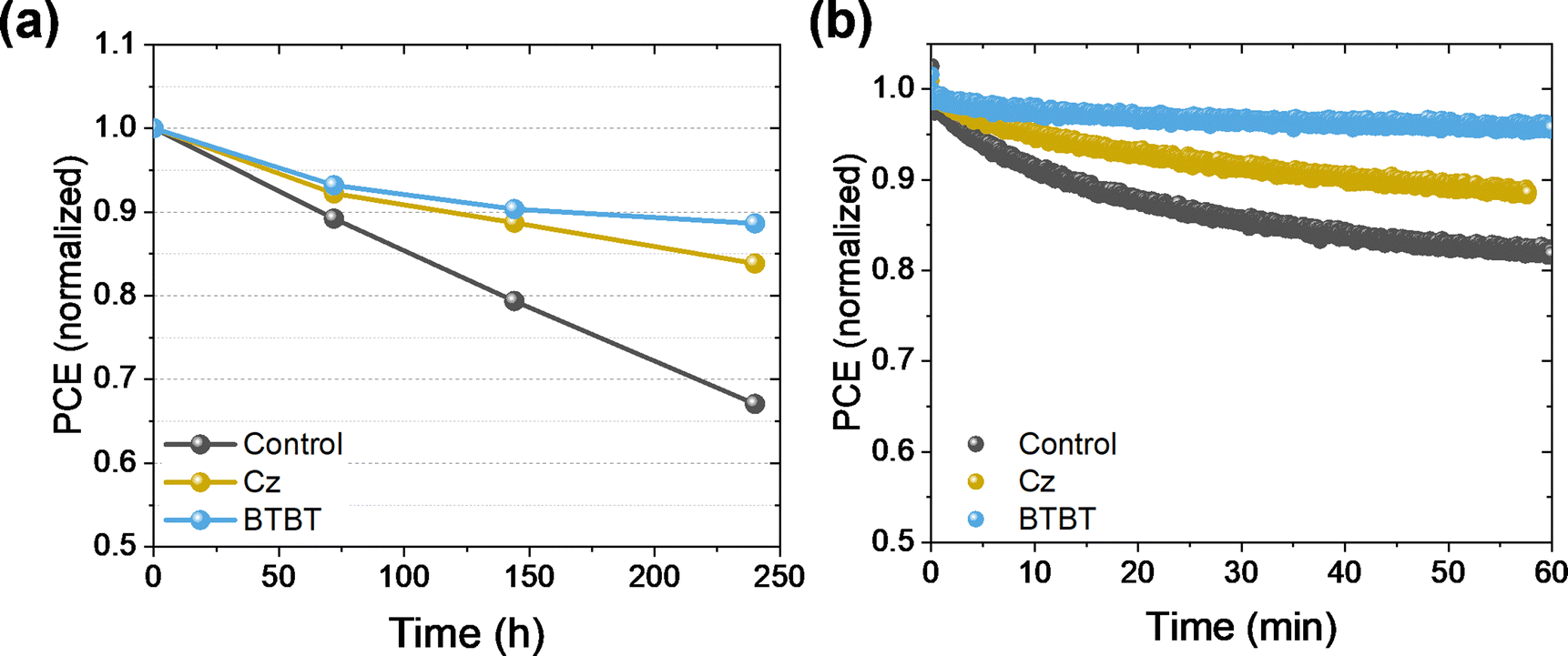
The PSCs were exposed to a relative humidity (RH) of 25% in the dark for 250 hours, and the PCE was measured at intervals of 70–100 hours to track the decline of the performance, as shown in Fig. 5. For both interlayers, a clear improvement in the stability is obtained, retaining 84% and 89% of the initial performance for Cz and BTBT, respectively, while the control cell (i.e. without the Cz or BTBT interlayer) only retained 67% of the initial performance. The critical factor for these cells was the FF, as the Jsc and Voc remained rather unchanged over the course of the tests (Fig. S3, ESI†), suggesting that the perovskite layer itself was not the most sensitive material to the stress conditions, but rather one of the interfaces. Given the positive effect of the interlayers on the stability, we hypothesize that the stabilization of the NiOx/perovskite interface is at least partly responsible for the improved stability. Additionally, samples with and without the interlayers were exposed to continuous illumination for an hour while held under maximum power point (MPP) conditions. Over this time, the interlayers significantly improve the stability under operational conditions, as the control only retained 82% of its initial performance while 88% and 95% was retained for Cz and BTBT, respectively. This also shows that the BTBT interlayer has a profound impact on improving the stability at the interface.
 |
| | Fig. 5 Stability test on PSCs without encapsulation in (a) ambient conditions (25% RH) and (b) under continuous illumination and MPPT conditions. | |
3. Conclusion and outlook
In summary, we have developed two new interface passivation materials based on benzothieno[3,2-b] benzothiophene (BTBT) and carbazole (Cz). These materials were introduced at the NiOx/perovskite interface in p-i-n perovskite solar cells, a key bottleneck for the device's performance and stability. The PSCs with the BTBT interlayer showed higher PCE and stability than the control and Cz-based devices. To get mechanistic insights, we performed XPS, HAXPS, PLQY, and TRPL measurements. These results show that passivation of the NiOx/perovskite interface via the BTBT derivative suppresses a (redox) reaction at this interface and significantly enhances the open-circuit voltage (Voc) by suppressing the non-radiative recombination. These results provide a design rationale for new passivation materials and self-assembled monolayers. We believe that the BTBT core can be combined with phosphonic acid functionalities to create new self-assembled monolayers in further work, given the success of Cz-based phosphonic acid SAMs.27–30
Author contributions
Stijn Lammar: investigation, validation, visualization, writing – original draft, conceptualization Wouter Van Gompel: conceptualization, investigation, supervision, writing – review & editing Stijn Lenaers: investigation, writing – review & editing Martijn Mertens: investigation Hans-Gerd Boyen: investigation, supervision, writing – review & editing Derese Desta: investigation Afshin Hadipour: supervision, writing – review & editing Laurence Lutsen: project administration, supervision, funding acquisition Dirk Vanderzande: conceptualization, supervision Anurag Krishna: writing – review & editing, visualization Yaser Abdulraheem: funding acquisition Tom Aernouts: project administration, supervision, funding acquisition Jef Poortmans: supervision.
Conflicts of interest
There are no conflicts to declare.
Acknowledgements
MM acknowledges the FWO for the funding of his PhD research (FWO, No. 1S20118N). WTMVG, SL, LL, and DV acknowledge the FWO for the funding of the SBO project PROCEED (S002019N) and the senior FWO research project G043320N. This study was supported by the Special Research Fund (BOF) of Hasselt University (BOF22PD01). HGB and DD are very grateful to the FWO for funding the HAXPES-lab instrument within the HERCULES program for Large Research Infrastructure of the Flemish government (project I014018N). The authors thank Bart Ruttens (IMO, UHasselt) for XRD measurements. This work is funded in part by the Kuwait Foundation for the Advancement of Sciences under project number CN18-15EE-01.
References
- M. A. Green, E. D. Dunlop, J. Hohl-Ebinger, M. Yoshita, N. Kopidakis and X. Hao, Prog. Photovoltaics, 2022, 30, 3–12 Search PubMed.
- C. C. Boyd, R. Cheacharoen, T. Leijtens and M. D. McGehee, Chem. Rev., 2019, 119, 3418–3451 CrossRef CAS PubMed.
- Z. Wang, Z. Shi, T. Li, Y. Chen and W. Huang, Angew. Chem., Int. Ed., 2017, 56, 1190–1212 CrossRef CAS PubMed.
- M. Ye, C. He, J. Iocozzia, X. Liu, X. Cui, X. Meng, M. Rager, X. Hong, X. Liu and Z. Lin, J. Phys. D: Appl. Phys., 2017, 50, 373002 CrossRef.
- Z. Guo, Z. Wu, Y. Chen, S. Wang and W. Huang, J. Mater. Chem. C, 2022, 10, 13611–13645 RSC.
- H. Xiang, P. Liu, W. Wang, R. Ran, W. Zhou and Z. Shao, Chem. Eng. J., 2021, 420, 127599 CrossRef CAS.
- T. Leijtens, G. E. Eperon, S. Pathak, A. Abate, M. M. Lee and H. J. Snaith, Nat. Commun., 2013, 4, 2885 CrossRef PubMed.
- W. Song, L. Rakocevic, R. Thiruvallur Eachambadi, W. Qiu, J. P. Bastos, R. Gehlhaar, Y. Kuang, A. Hadipour, T. Aernouts and J. Poortmans, ACS Appl. Mater. Interfaces, 2021, 13, 44294–44301 CrossRef CAS PubMed.
- H. Lee, Y.-T. Huang, M. W. Horn and S.-P. Feng, Sci. Rep., 2018, 8, 5590 CrossRef PubMed.
- X. Zheng, Z. Song, Z. Chen, S. S. Bista, P. Gui, N. Shrestha, C. Chen, C. Li, X. Yin, R. A. Awni, H. Lei, C. Tao, R. J. Ellingson, Y. Yan and G. Fang, J. Mater. Chem. C, 2020, 8, 1972–1980 RSC.
- N. Pant, A. Kulkarni, M. Yanagida, Y. Shirai, T. Miyasaka and K. Miyano, Adv. Mater. Interfaces, 2020, 7, 1901748 CrossRef CAS.
- C. C. Boyd, R. C. Shallcross, T. Moot, R. Kerner, L. Bertoluzzi, A. Onno, S. Kavadiya, C. Chosy, E. J. Wolf, J. Werner, J. A. Raiford, C. de Paula, A. F. Palmstrom, Z. J. Yu, J. J. Berry, S. F. Bent, Z. C. Holman, J. M. Luther, E. L. Ratcliff, N. R. Armstrong and M. D. McGehee, Joule, 2020, 4, 1759–1775 CrossRef CAS.
- L. Xu, X. Chen, J. Jin, W. Liu, B. Dong, X. Bai, H. Song and P. Reiss, Nano Energy, 2019, 63, 103860 CrossRef CAS.
- W. Chen, Y. Wu, J. Fan, A. B. Djurišić, F. Liu, H. W. Tam, A. Ng, C. Surya, W. K. Chan, D. Wang and Z. He, Adv. Energy Mater., 2018, 8, 1703519 CrossRef.
- H. Zhu, Y. Liu, F. T. Eickemeyer, L. Pan, D. Ren, M. A. Ruiz-Preciado, B. Carlsen, B. Yang, X. Dong, Z. Wang, H. Liu, S. Wang, S. M. Zakeeruddin, A. Hagfeldt, M. I. Dar, X. Li and M. Grätzel, Adv. Mater., 2020, 32, 1907757 CrossRef CAS PubMed.
- B. Chen, H. Chen, Y. Hou, J. Xu, S. Teale, K. Bertens, H. Chen, A. Proppe, Q. Zhou, D. Yu, K. Xu, M. Vafaie, Y. Liu, Y. Dong, E. H. Jung, C. Zheng, T. Zhu, Z. Ning and E. H. Sargent, Adv. Mater., 2021, 33, 2103394 CrossRef CAS PubMed.
- P. Denis, M. Mertens, W. T. M. Van Gompel, A. Maufort, S. Mertens, Z. Wei, M. Van Landeghem, S. Gielen, B. Ruttens, D. Deduytsche, C. Detarvernier, L. Lutsen, F. Grozema, K. Vandewal and D. Vanderzande, Adv. Opt. Mater., 2022, 10, 2200788 CrossRef CAS.
- K. Takimiya, I. Osaka, T. Mori and M. Nakano, Acc. Chem. Res., 2014, 47, 1493–1502 CrossRef CAS PubMed.
- Y. Kiyota, T. Kadoya, K. Yamamoto, K. Iijima, T. Higashino, T. Kawamoto, K. Takimiya and T. Mori, J. Am. Chem. Soc., 2016, 138, 3920–3925 CrossRef CAS PubMed.
- R. Janneck, N. Pilet, S. P. Bommanaboyena, B. Watts, P. Heremans, J. Genoe and C. Rolin, Adv. Mater., 2017, 29, 1703864 CrossRef PubMed.
- C. Niebel, Y. Kim, C. Ruzié, J. Karpinska, B. Chattopadhyay, G. Schweicher, A. Richard, V. Lemaur, Y. Olivier, J. Cornil, A. R. Kennedy, Y. Diao, W. Lee, S. Mannsfeld, Z. Bao and Y. H. Geerts, J. Mater. Chem. C, 2015, 3, 674–685 RSC.
- W. T. M. Van Gompel, R. Herckens, P. H. Denis, M. Mertens, M. C. Gélvez-Rueda, K. Van Hecke, B. Ruttens, J. D’Haen, F. C. Grozema, L. Lutsen and D. Vanderzande, J. Mater. Chem. C, 2020, 8, 7181–7188 RSC.
- X. Yang, D. Luo, Y. Xiang, L. Zhao, M. Anaya, Y. Shen, J. Wu, W. Yang, Y. H. Chiang, Y. Tu, R. Su, Q. Hu, H. Yu, G. Shao, W. Huang, T. P. Russell, Q. Gong, S. D. Stranks, W. Zhang and R. Zhu, Adv. Mater., 2021, 33, 1–10 Search PubMed.
- J. Li, L. Zuo, H. Wu, B. Niu, S. Shan, G. Wu and H. Chen, Adv. Funct. Mater., 2021, 2104036, 1–10 Search PubMed.
- O. Sambalova, E. Billeter, J. Mann, T. Miyayama, D. Burnat, A. Heel, D. Bleiner and A. Borgschulte, Surf. Interface Anal., 2020, 52, 811–817 CrossRef CAS.
- NIST X-ray Photoelectron Spectroscopy (XPS) Database, https://srdata.nist.gov/xps/main_search_menu.aspx, (accessed December 2022).
- S. Chen, C. Zuo, B. Xu and L. Ding, J. Semicond., 2021, 42, 120203 CrossRef.
- A. Magomedov, A. Al-Ashouri, E. Kasparavičius, S. Strazdaite, G. Niaura, M. Jošt, T. Malinauskas, S. Albrecht and V. Getautis, Adv. Energy Mater., 2018, 8, 1801892 CrossRef.
- S. Y. Kim, S. J. Cho, S. E. Byeon, X. He and H. J. Yoon, Adv. Energy Mater., 2020, 10(44), 2002606 CrossRef CAS.
- J. Dagar, M. Fenske, A. Al-Ashouri, C. Schultz, B. Li, H. Köbler, R. Munir, G. Parmasivam, J. Li, I. Levine, A. Merdasa, L. Kegelmann, H. Näsström, J. A. Marquez, T. Unold, D. M. Többens, R. Schlatmann, B. Stegemann, A. Abate, S. Albrecht and E. Unger, ACS Appl. Mater. Interfaces, 2021, 13, 13022–13033 CrossRef CAS PubMed.
Footnote |
| † Electronic supplementary information (ESI) available: Materials used, details on device processing, characterization, and the lift-off process, JV performance on PTAA, stability data and extracted data from TRPL measurements. See DOI: https://doi.org/10.1039/d2tc04215k |
|
| This journal is © The Royal Society of Chemistry 2023 |
Click here to see how this site uses Cookies. View our privacy policy here. 
 *abcd,
Wouter
Van Gompel
*abcd,
Wouter
Van Gompel