 Open Access Article
Luminescence-based circular polarization convertors: polarization conversion of linearly polarized photoluminescence from one-dimensionally aligned quantum rods using retardation films†
Yutaka
Okazaki
 *,
Misaki
Kimura
,
Kan
Hachiya
 and
Takashi
Sagawa
 *
*
Graduate School of Energy Science, Kyoto University Yoshida-Honmachi, Sakyo-ku, 606-8501 Kyoto, Japan. E-mail: okazaki.yutaka.8c@kyoto-u.ac.jp; sagawa.takashi.6n@kyoto-u.ac.jp
First published on 16th December 2022
Abstract
Existing methods for generating circularly polarized (CP) light from an unpolarized light source without using external electrical energy have drawbacks, such as a trade-off relationship between CP light intensity and purity. Here, we demonstrate an approach for the generation of high-purity, high-intensity CP light based on a luminescence-based CP convertor composed of a linearly polarized luminescence (LPL) film and a quarter-wave plate. The LPL films, fabricated by one-dimensional alignment of semiconductor quantum rods and laminated with a quarter-wave plate, enabled effective conversion of LPL to high-purity CP light and retained the photoluminescent spectral pattern, light intensity, and the large degree of polarization. The sign of CP light was easily switched by changing the orientation of the quarter-wave plate and the LPL polarization plane. Furthermore, we also demonstrate the first example of parallel-type and multi-layered luminescence-based CP light convertors for multiplexing optical information. Our findings will aid the design of next-generation CP light-generating materials.
Introduction
Circularly polarized (CP) visible light is gathering worldwide attention as a next-generation light source because it exhibits extensive optical information, a wide viewing angle, and asymmetric effects, such as chiral induction,1 enantioselective chemical reactions,2,3 and enhancement of the energy conversion efficiency of photovoltaics (inverse Faraday effect).4 In recent years, the improvement of various optical properties, such as the polarization degree, light intensity, and color tunability, has been considered an important issue in the generation of CP light. The majority of the reported approaches for creating CP visible light from unpolarized light without using external electrical energy can be roughly classified into three categories, namely, filtration using a circular polarizer, selective reflection by chiral liquid crystal structures,5 and circularly polarized luminescence (CPL) from chiral materials.6 A classical filtering method using a circular polarizer made from a linear polarizer and quarter-wave plate has been widely used, especially in the field of optics, because it can produce high-purity CP light with high reliability. A selective reflection method using chiral liquid crystal structures, which is based on biomimetics,7 can also produce high-purity CP light with unique properties, such as angular dependence of color (structural color) owing to Bragg's law. Another unique property of this approach is that CP transmitted light has an opposite signal to that of CP reflected light. The significantly high polarization degree of CP light obtained from the above two methods originates from the precise filtration or separation of the one-sided CP light, resulting in a theoretical light intensity limitation of less than 50%. In contrast to the above two approaches, the CPL approach allows various highly emissive CP luminophores exhibiting various emission colors to be selected. However, the quantum yield (ϕ), indicating luminescence intensity, and the dissymmetry factor (glum), indicating the polarization degree of CP light upon luminescence, are generally in a trade-off relationship.8 Therefore, despite remarkable recent progress in CP light generation, the creation of high-purity CP visible light with high light intensity remains an important challenge.Linearly polarized luminescence (LPL), on the other hand, has no theoretical constraints in achieving both high polarization degree and high light intensity. Various approaches have been reported for the fabrication of LPL materials, including stretching,9a the fiber-directed method,9b shearing,9c–e rubbing,9f evaporation,9g,h the Langmuir–Blodgett method,9i,j external field,9k and photo-induction.9l–n However, effective use of LPL films for producing high-purity CP visible light with high light intensity, has not been investigated so far, not to mention the effect of multilayering of LPL films.
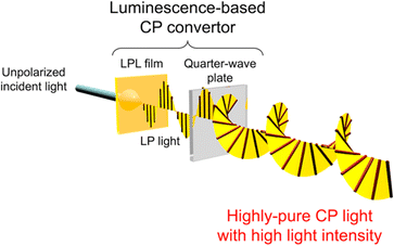
Here, we demonstrate an approach based on the polarization conversion of LPL to produce high-purity CP visible light with high light intensity (Fig. 1). This approach enables various achiral photoluminescent (PL) dyes to be selected. Therefore, the emission color and light intensity can be easily tuned using the PL spectra and quantum yield of dyes. By laminating a quarter-wave plate on the LPL material, the polarization degree of LPL is directly converted to the polarization degree of CP light (PCP), resulting in an extremely large PCP value. The sign (right-handed (RH) or left-handed (LH)) of CP light can be easily switched with retention of the PL spectral pattern and intensity by simply changing the angle between the fast axis of the quarter-wave plate and polarization plane of LPL from +45° to −45° (or from −45° to +45°).
In comparison with a circular polarizer, a luminescence-based CP convertor uses a LPL film instead of a linear polarizer. The most significant difference between LPL films and linear polarizers is the spectral conversion properties derived from the photoluminescent phenomenon. Taking advantage of spectral conversion properties of LPL films, LP light at desired wavelength can be produced from incident light at undesired wavelength. From the viewpoint of energy loss, when unpolarized light at desired wavelength is filtered by a linear polarizer, more than half of light energy is cut off. In contrast, in the case of LPL films, the emitted light at desired wavelength is already highly polarized. Therefore, light energy loss can be prevented by using LPL films, even when combined with a linear polarizer. Further advantage of this approach can be found in the multilayering of LPL films. Details will be given later.
In the present paper, LPL films were fabricated by the one-dimensional alignment of semiconductor quantum rods (QRs) with the following advantages: (i) LPL can be generated along the long axis of nanorods; (ii) a high molar coefficient and quantum yield are obtained, which lead to a high light intensity; (iii) a sharp PL peak; and (iv) various QRs with different emission colors can be excited at one selected wavelength by taking advantage of the semiconductor features. The latter two features are key properties for the multiplexing of optical information from a CP light convertor. Herein, we demonstrate that our luminescence-based CP conversion approach provides high-purity CP light that is easily detected by the naked eye using a circular polarizer. We also demonstrated switching of the sign of CP light by simply changing the angle between the fast axis of the quarter-wave plate and polarization plane of LPL, and multiplexing of the optical information using parallel-type and multi-layered luminescence-based CP light convertors.
Results and discussion
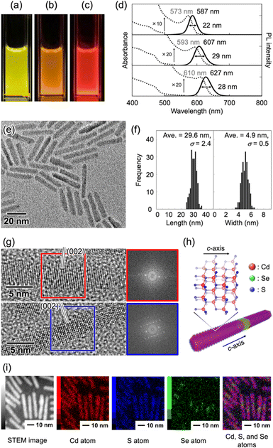
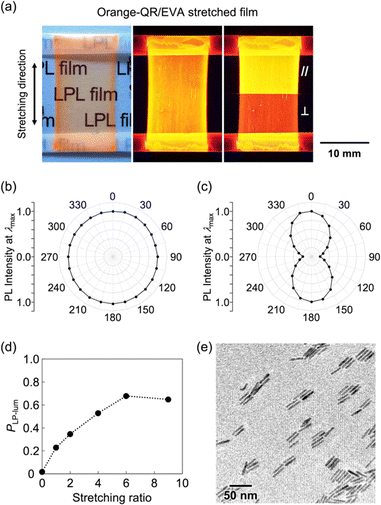
In this study, CdSe/CdS core/shell QRs were selected because the emission color can be easily tuned by selecting the size of the CdSe core particles. CdSe/CdS core/shell QRs were synthesized by the hot-injection method (see ESI†).10 When CdSe quantum dots showing different emission colors were used as core particles (Fig. S1–S3, ESI†), the obtained solutions showed yellow-, orange-, and red-colored emission under UV light irradiation, respectively (Fig. 2a–c). Fig. 2d shows UV-vis and PL spectra of these three solutions. UV-vis spectra of yellow-, orange-, and red-QRs showed clear first absorption peaks at 573, 593, and 610 nm, respectively, corresponding to the energy gap between the valence and conduction bands of the CdSe core. The broad absorption bands below 500 nm, which were attributed to energy gaps between the valence and conduction bands of the CdS shell, were observed from all three solutions. In the PL spectral measurements, sharp emission peaks were observed at 587 nm (FWHM = 22 nm) from yellow-QRs, 607 nm (FWHM = 29 nm) from orange-QRs, and 627 nm (FWHM = 28 nm) from red-QRs, respectively. The QR morphologies were evaluated by transmission electron microscopy (TEM) observation. TEM images of the dried samples of the QR toluene solutions showed quite uniform rod-like nanostructures. To quantitatively analyze the morphology, the length and width of 200 nanorods in TEM images were measured. For the orange-QRs, the average length was 29.6 nm (σ = 2.4) and the average width was 4.9 nm (σ = 0.5), as shown in Fig. 2e and f. The morphologies of the yellow-QRs and red-QRs were also evaluated, as summarized in Fig. S4 and S5 (ESI†). The crystal structure of nanorods was evaluated by high-resolution TEM (HR-TEM) observation and from its fast Fourier transformation (FFT) pattern. As shown in Fig. 2g, clear periodic patterns were observed. Both top and bottom HR-TEM images show the same lattice spacing (3.4 Å) along the long axis of nanorods, which is in agreement with that of the (002) lattice planes of a hexagonal wurtzite-type CdS crystal (Fig. 2h).10a,11,12a This is consistent with a preferential growth of CdS shells along the c-axis of the wurtzite-type crystal structure without change in the diameter. Element mapping of the nanorods was conducted using scanning transmission electron microscopy–energy dispersive X-ray spectroscopy (STEM-EDX). As shown in Fig. 2i, Cd and S atoms were located homogeneously in nanorods, while Se atoms were localized close to the center of the nanorods, confirming that the nanorods consisted of a CdS rod-like shell and CdSe core.In general, the LPL properties of QRs significantly degraded in homogeneous bulk materials owing to their random orientation. To extract and maximize the LPL properties of QRs on the macroscale, the QRs were oriented in one direction (1D) by uniaxial stretching of the composite polymer films. In this study, we selected poly(ethylene-co-vinyl acetate) (EVA) as a stretchable polymer because of its transparency, elasticity, solubility, and adhesive properties on various substrates. The QR/toluene solution was mixed with an EVA/toluene solution, and the mixture was cast on a glass substrate. After drying in air, the composite polymer film was stretched in one direction and attached to a glass substrate. For orange-QRs, the obtained orange-QR/EVA 1D-stretched film showed good transparency, orange-colored strong luminescence under UV light, and different luminescence intensities under a linear polarizer placed parallel and perpendicular to the stretching direction (Fig. 3a). Similar results were observed for the yellow- and red-QR/EVA stretched films (Fig. S6, ESI†). These results indicated that the obtained 1D-stretched composite films showed yellow-, orange-, and red-colored PL with strong linear polarization sufficient to be detected by the naked eye using a linear polarizer.
For detailed evaluation of the 1D-stretched QR/EVA composite films, the effect of the stretching ratio on the degree of linear polarization in photoluminescence was first studied. Fig. 3b and c shows the angular dependencies of PL intensities at the highest peak (λmax) before and after 1D stretching of QR/EVA composite films. The unstretched film showed no significant angular dependence on the PL intensity, while the 1D-stretched film showed maximum values at 0° and 180°, and minimum values at 90° and 270°. The degree of linear polarization in photoluminescence (PLP-lum) was calculated using the following equation:
 | (1) |
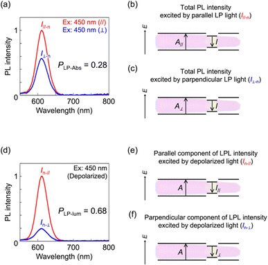
To further investigate the linear polarization properties of 1D-stretched QR/EVA composite films, the degree of linear polarization in the absorption process (PLP-Abs) was studied. The PLP-Abs value was calculated from PL intensities excited with parallel and perpendicular LP light at 450 nm (Fig. 4a). The obtained value (PLP-Abs = 0.28) was clearly smaller than the degree of linear polarization in PL (PLP-lum = 0.68, Fig. 4d). These results suggest that the fabricated LPL films play a role in efficiently converting unpolarized light into linearly polarized light, since they exhibit a small PLP-Abs value and a large PLP-lum value. These results also indicate that the mechanism of linear polarization generation differs between the absorption process (PLP-Abs) and emission process (PLP-lum), which is in good agreement with the mechanism reported previously.12 In the absorption process, linear polarization mainly originates from the dielectric effect based on the morphological anisotropy of QRs. Namely, the rod-shaped CdS shell part mainly provides the linear polarization in the absorption process. In contrast, in the emission process, linear polarization is mainly derived from the quantum confinement effect based on the QR width being smaller than the exciton size. Indeed, the average widths of yellow-, orange-, and red-QRs were 4.6 nm, 4.9 nm, and 5.7 nm, respectively, which were sufficiently smaller than the exciton size (10.6–10.8 nm) calculated from the previously reported CdSe exciton Bohr radius (5.3–5.4 nm).13
To fabricate a luminescence-based CP convertor, a 1D stretched QR/EVA composite film was laminated with a quarter-wave plate where the fast axis was placed at −45° to the stretching direction (see ESI†). When the 1D-stretched film was directly laminated on a quarter-wave plate, a flexible-type luminescence-based CP convertor was prepared (Fig. S10, ESI†). When the PL was observed through a RH or LH circular polarizer, brighter light was observed through the LH circular polarizer. Quantitative evaluation of the RH- and LH-CP light components, as measured using a PL spectrometer with a CP light detection setup (see ESI†), confirmed that the total emission included 83% LH-CP light and 17% RH-CP light (Fig. 5a, left). The degree of circular polarization in the photoluminescence (PCP) was calculated using the following equation:
 | (2) |
 | (3) |
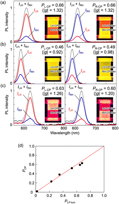 | ||
| Fig. 5 PL spectra of (a) orange-, (b) yellow-, and (c) red- CP convertors. Excitation wavelength, 450 nm. All the spectra on the left (or right) were obtained from LH- (or RH-) CP convertors, respectively. LH- and RH-CP light components in the PL were measured using a photodetector with a CP light detection optical setup (see ESI†). Insets are photographs of (a) orange-, (b) yellow-, and (c) red- LH- (left) and RH- (right) CP convertors under UV light at 365 nm. Luminescence of these CP convertors was observed through LH- and RH-CP filters. (d) Correlation between the PLP-lum and PCP values. The red line is the theoretical curve. | ||
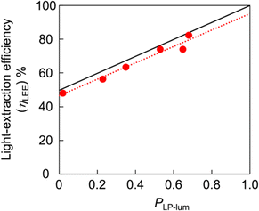
A unique advantage of the CP convertor was observed when a linear polarizer was combined with it. When a linear polarizer was placed between the LPL film and quarter-wave plate, almost completely single-handed CP light (PCP > 0.95) was produced because the perpendicular component of emitted light was almost perfectly cut off. If the PLP-lum value of an LPL film is maximum (PLP-lum = 1), the light intensity of transmitted light from the total PL intensity, defined as the light-extraction efficiency (ηLEE), will be 100% in theory. In contrast, the light-extraction efficiency of nonpolarized PL will ideally be 50%. Linear correlation between the ηLEE value and PLP-lum value was observed, as summarized in the following equation:
 | (4) |
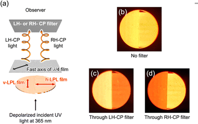
The luminescence-based CP convertor composed of several LPL films made a significant contribution in multiplexing optical information. The first example was observed in the parallel arrangement of LPL films with the same PL spectral pattern. As shown in Fig. 7a, the QR/EVA composite film stretched vertically (v-LPL film) was placed on the left side, and another film stretched horizontally (h-LPL film) was placed on the right side. When the fast axis of the quarter-wave plate was adjusted to be at +45° in the vertical direction and at −45° in the horizontal direction, the CP convertor produced LH-CP light on the left side and RH-CP light on the right side. Although the difference in CP-light handedness was not detectable by the naked eye alone, the use of LH- and RH-CP filters allowed clear observation by the naked eye, as shown in Fig. 7b–d. These results indicated that the luminescence-based CP conversion approach enabled multiplex optical anisotropy by patterning the orientation of LPL generating agents.
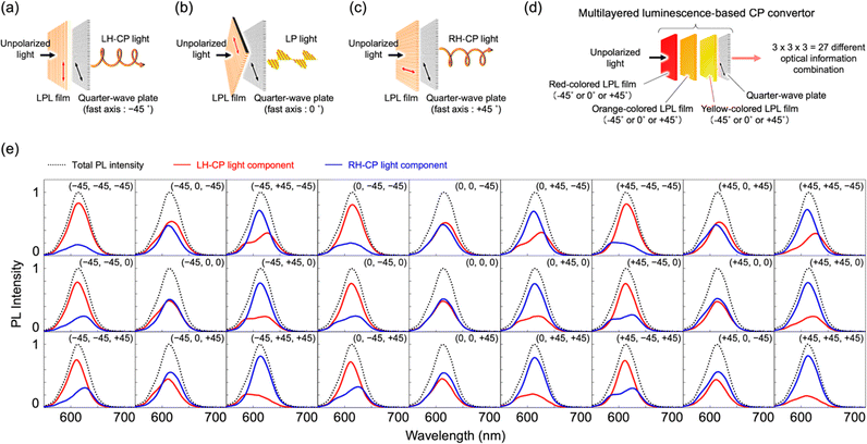
The second example was observed in multi-layered LPL films exhibiting different PL colors. When the angles between the polarization plane of the LPL film and fast axis of the quarter-wave plate were −45°, 0°, and +45°, LH-CP, parallel LP, and RH-CP light were produced, as shown in Fig. 8a–c, respectively. Taking advantage of this, further multiplexing of the optical information was demonstrated by laminating different color-emitting LPL films at different angles between the polarization plane of the LPL film and the fast axis of the quarter-wave plate. To the best of our knowledge, this is the first time that such a multi-layer LPL film system has been fabricated and investigated. When the yellow-, orange-, and red-color-emitting LPL films were laminated at three different angles (−45°, 0°, and +45°) against the fast axis of the quarter-wave plate, 27 possible pieces of optical information were estimated to be produced, as shown in Fig. 8d. By measuring PL spectra of all combinations, we confirmed that 27 different pieces of optical information, as combinations of wavelength, PL intensity, and polarization, were produced from a three-layered luminescence-based CP convertor by only selecting the angle (Fig. 8e). Interestingly, the difference between these 27 pieces of optical information was not clearly detected by the naked eye using CP filters (Fig. S12, ESI†), in contrast to the parallel-type CP convertor (Fig. 7). These results indicate that the multi-layered luminescence-based CP convertor has potential for use in high-level security printing.
Conclusions
We have reported the first example of the generation of high-purity CP light with high light intensity based on a luminescence-based CP convertor composed of an LPL film and a quarter-wave plate. The synthesized yellow-, orange-, and red-QRs showed significant LPL when oriented by 1D stretching of the composite polymer films. After lamination of these LPL films with a quarter-wave plate, LPL was effectively converted to high-purity CP light with retention of the PL spectral pattern, light intensity, and the large degree of polarization (e.g., PCP = 0.66, which corresponds to |glum| = 1.32). The sign of CP light was easily switched by simply changing the angle between the fast axis of the quarter-wave plate and the polarization plane of LPL from +45° to −45° (or from −45° to +45°). Completely single-handed CP light (PCP, ∼0.95) was also produced when a linear polarizer was placed between the LPL film and quarter-wave plate owing to almost perfect cutting-off of the perpendicular component of emitted light. The equations obtained from both theoretical and experimental studies indicated that a high light-extraction efficiency (ηLEE) and a high polarization degree (PLP-lum, namely PCP) can be achieved at the same time. At this point, the luminescence-based CP convertor is totally different from the other CP convertors. Furthermore, we also demonstrate the first example of parallel-type and multi-layered luminescence-based CP light convertors for multiplexing of optical information. These findings will help designing next-generation CP light-generating materials for various fields, including photoelectric conversion, plant factory, and security printing.Author contributions
Y. Okazaki designed the project, raised funds, and wrote the original draft. All the experimental measurements, observation, analysis were carried out by Y. Okazaki and M. Kimura with equal contribution. T. Sagawa assisted the synthesis of various quantum rods and its analysis. K. Hachiya assisted the mechanistic consideration of the origin of linear polarization in the light absorption and emission processes. All authors discussed the results and contributed to the interpretation of the data.Conflicts of interest
There are no conflicts to declare.Acknowledgements
This work was supported by JSPS KAKENHI (grant number 19K15376 and 20KK0122), SPIRITS2020 from Kyoto University, the Kansai Research Foundation for Technology Platform, and the Masuyakinen Basic Research Foundation. We are grateful to T. Kiyomura from the Institute for Chemical Research, Kyoto University for TEM, HRTEM, and STEM-EDX observation, which was supported by Kyoto University Nano Technology Hub in the Nanotechnology Platform Project sponsored by the Ministry of Education, Culture, Sports, Science and Technology (MEXT), Japan (grant numbers JPMXP09A21KT0014, and JPMXP1222KT0001).Notes and references
- (a) G. Iftime, F. L. Labarthet, A. Natansohn and P. Rochon, J. Am. Chem. Soc., 2000, 122, 12646–12650 CrossRef CAS; (b) Y. Wang, T. Sakamoto and T. Nakano, Chem. Commun., 2014, 48, 1871–1873 RSC; (c) T. Nakano, Chem. Rec., 2014, 14, 369–385 CrossRef CAS PubMed; (d) M. Fujiki, Y. Donguri, Y. Zhao, A. Nakao, N. Suzuki, K. Yoshida and W. Zhang, Polym. Chem., 2015, 6, 1627–1638 RSC.
- (a) T. Manaka, H. Kon, Y. Ohshima, G. Zou and M. Iwamoto, Chem. Lett., 2006, 35, 1028–1029 CrossRef CAS; (b) S.-T. Wu, Z.-W. Cai, Q.-Y. Ye, C.-H. Weng, X.-H. Huang, X.-L. Hu, C.-C. Huang and N.-F. Zhuang, Angew. Chem., Int. Ed., 2014, 53, 12860–12864 CrossRef CAS PubMed; (c) M. Miyata, M. Teraguchi, H. Endo, T. Kaneko and T. Aoki, Chem. Lett., 2014, 43, 1476–1477 CrossRef CAS.
- (a) G. C. McLeod, Limnol. Oceanogr., 1957, 7, 360–362 CrossRef; (b) P. P. Shibaye and R. G. Pergolizzi, Int. J. Bot., 2011, 7, 113–117 CrossRef; (c) E. Lkhamkhuu, K. Zikihara, H. Katsura, S. Tokutomi, T. Hosokawa, Y. Usami, M. Ichihashi, J. Yamaguchi and K. Monde, Plant Biotechnol., 2020, 37, 57–67 CrossRef CAS PubMed.
- (a) J. Gilot, R. Abbel, G. Lakhwani, E. W. Meijer, A. P. H. J. Schenning and S. C. J. Meskers, Adv. Mater., 2010, 22, E131–E134 CrossRef CAS PubMed; (b) W. Qin, H. Xu and B. Hu, ACS Photonics, 2017, 4, 2821–2827 CrossRef CAS; (c) M. Wei, X. Hao, A. B. Saxena, W. Qin and S. Xie, J. Phys. Chem. C, 2018, 122, 12566–12571 CrossRef CAS.
- (a) S. H. Chen, D. Katsis, A. W. Schmid, J. C. Mastrangelo, T. Tsutsui and T. N. Blanton, Nature, 1999, 397, 506–5084 CrossRef CAS; (b) H.-J. Lee, B. R. Lee, S.-W. Choi and M. H. Song, Opt. Express, 2012, 20, 24473–24481 Search PubMed; (c) S. Furumi, Poly. J., 2013, 45, 579–593 CrossRef CAS; Y. Nagata, K. Takagi and M. Suginome, J. Am. Chem. Soc., 2014, 136, 9858–9861 Search PubMed; (d) K. Akagi, Bull. Chem. Soc. Jpn., 2019, 92, 1509–1655 CrossRef CAS.
- (a) E. M. Sánchez-Carnerero, A. R. Agarrabeitia, F. Moreno, B. L. Maroto, G. Muller, M. J. Ortiz and S. de la Moya, Chem. – Eur. J., 2015, 21, 13488–13500 CrossRef PubMed; (b) J. Kumar, T. Nakashima and T. Kawai, J. Phys. Chem. Lett., 2015, 6, 3445–3452 CrossRef CAS PubMed; (c) Y. Sang, J. Han, T. Zhao, P. Duan and M. Liu, Adv. Mater., 2020, 32, 1900110 CrossRef CAS PubMed; (d) G. Albano, G. Pescitelli and L. Di Bari, Chem. Rev., 2020, 120, 10145–10243 CrossRef CAS PubMed; (e) S. Jiang and N. A. Kotov, Adv. Mater., 2022, 2108431 CrossRef PubMed.
- (a) A. C. Neville and S. Caveney, Biol. Rev., 1969, 44, 531–562 CrossRef CAS PubMed; (b) D. J. Brink, N. G. van der Berg, L. C. Prinsloo and I. J. Hodgkinson, J. Phys. D: Appl. Phys., 2007, 40, 2189–2196 CrossRef CAS; (c) S. A. Jewell, P. Vukusic and N. W. Roberts, New J. Phys., 2007, 9, 99 CrossRef; (d) T.-H. Chiou, S. Kleinlogel, T. Cronin, R. Caldwell, B. Loeffler, A. Siddiqi, A. Goldizen and J. Marshall, Curr. Biol., 2008, 18, 429–434 CrossRef CAS PubMed; (e) S. Vignolini, P. J. Rudall, A. V. Rowland, A. Reed, E. Moyroud, R. B. Faden, J. J. Baumberg, B. J. Glover and U. Steiner, Proc. Natl. Acad. Sci. U. S. A., 2012, 109, 15712–15715 CrossRef CAS PubMed.
- (a) P. M. L. Block and H. P. J. M. Dekkers, Chem. Phys. Lett., 1989, 161, 188–194 CrossRef; (b) Y. Nagata and T. Mori, Front. Chem., 2020, 8, 448 CrossRef CAS PubMed; (c) L. Arrico, L. Di Bari and F. Zinna, Chem. – Eur. J., 2021, 27, 2920–2934 CrossRef CAS PubMed.
- (a) P. D. Cunningham, J. B. Souza Jr., I. Fedin, C. She, B. Lee and D. V. Talapin, ACS Nano, 2016, 10, 5769–5781 CrossRef CAS PubMed; (b) A. Chakrabarty, G. Raffy, M. Maity, L. Gartzia-Rivero, S. Marre, C. Aymonier, U. Maitra and A. D. Guerzo, Small, 2018, 14, 1802311 CrossRef PubMed; (c) Y. Sagara, A. Seki, Y. Kim and N. Tamaoki, J. Mater. Chem. C, 2018, 6, 8453–8459 RSC; (d) J. Koo, S.-I. Lim, S. H. Lee, J. S. Kim, Y.-T. Yu, C.-R. Lee, D.-Y. Kim and K.-U. Jeong, Macromolecules, 2019, 52, 1739–1745 CrossRef CAS; (e) L. Tao, K. Lan, C.-L. Zhong, Y.-J. Zhou, P. Wang, F. Fan, Z. Shen and H.-L. Xie, J. Mater. Chem. C, 2020, 8, 16561–16568 RSC; (f) R. A. M. Hikmet, P. T. K. Chin, D. V. Talapin and H. Weller, Adv. Mater., 2005, 17, 1436–1439 CrossRef CAS PubMed; (g) Z. Zhou, H. Liu, W. Zhang, Z. Wen, J. Hao, B. Xu, K. Wang, K.-L. Teo and X.-W. Sun, IEEE J. Quantum Electron., 2019, 55, 710026 CAS; (h) H. He, J. Liu, K. Li, Z. Yin, J. Wang, D. Luo and Y. J. Liu, Nano Lett., 2020, 20, 4204–4210 CrossRef CAS PubMed; (i) A. Rizzo, C. Nobile, M. Mazzeo, M. D. Giorgi, A. Fiore, L. Carbone, R. Cingolani, L. Manna and G. Gigli, ACS Nano, 2009, 3, 1506–1512 CrossRef CAS PubMed; (j) K. Yoshihara, M. Yamanaka, S. Kanno, S. Mizushima, J. Tsuchiyagaito, K. Kondo, T. Kondo, D. Iwasawa, H. Komiya, A. Saso, S. Kawaguchi, K. Goto, S. Ogata, H. Takahashi, A. Ishii and M. Hasegawa, New J. Chem., 2019, 43, 6472–6479 RSC; (k) S. Kaur, G. Murali, R. Manda, Y. C. Chae, M. Yun, J. H. Lee and S. H. Lee, Adv. Opt. Mater., 2018, 6, 1800235 CrossRef; (l) T. Du, J. Schneider, A. K. Srivastava, A. S. Sucha, V. G. Chigrinov., H. S. Kwok and A. L. Rogachi, ACS Nano, 2015, 9, 11049–11055 CrossRef CAS PubMed; (m) K. Hisano, M. Aizawa, M. Ishizu, Y. Kurata, W. Nakano, N. Akamatsu, C. J. Barrett and A. Shishido, Sci. Adv., 2017, 3, e1701610 CrossRef PubMed; (n) W. Zhang, J. Schneider, V. G. Chigrinov, H. S. Kwok, A. L. Rogach and A. K. Srivastava, Adv. Opt. Mater., 2018, 6, 1800250 CrossRef.
- (a) L. Carbone, C. Nobile, M. De Giorgi, F. D. Sala, G. Morello, P. Pompa, M. Hytch, E. Snoeck, A. Fiore, I. R. Franchini, M. Nadasan, A. F. Silvestre, L. Chiodo, S. Kudera, R. Cingolani, R. Krahne and L. Manna, Nano Lett., 2007, 7, 2942–2950 CrossRef CAS PubMed; (b) J. Dehnel, Y. Barak, I. Meir, A. K. Budniak, A. P. Nagvenkar, D. R. Gamelin and E. Lifshitz, ACS Nano, 2020, 14, 13478–13490 CrossRef CAS PubMed.
- S. Kumar and T. Nann, Small, 2006, 2, 316–329 CrossRef CAS PubMed.
- (a) D. V. Talapin, R. Koeppe, S. Gotzinger, A. Kornowski, J. M. Lupton, A. L. Rogach, O. Benson, J. Feldmann and H. Weller, Nano Lett., 2003, 3, 1677–1681 CrossRef CAS; (b) A. Sitt, A. Salant, G. Menagen and U. Banin, Nano Lett., 2011, 11, 2054–2060 CrossRef CAS PubMed; (c) J. S. Kamal, R. Gomes, Z. Hens, M. Karvar, K. Neyts, S. Compernolle and F. Vanhaecke, Phys. Rev. B: Condens. Matter Mater. Phys., 2012, 85, 035126 CrossRef; (d) I. Hadar, G. B. Hitin, A. Sitt, A. Faust and U. Banin, J. Phys. Chem. Lett., 2013, 4, 502–507 CrossRef CAS PubMed; (e) Y. Ge, M. Zhang, L. Wang, L. Meng, J. Tang, Y. Chen, L. Wang and H. Zhong, Adv. Opt. Mater., 2019, 7, 1900330 CrossRef.
- (a) K. Kyhm, J. H. Kim, S. M. Kim and H. Yang, Opt. Mater., 2007, 30, 158–160 CrossRef CAS; (b) V. Babentsov and F. Sizov, Opto-Electron. Rev., 2008, 16, 208–225 CAS.
Footnote |
| † Electronic supplementary information (ESI) available. See DOI: https://doi.org/10.1039/d2tc03955a |
| This journal is © The Royal Society of Chemistry 2023 |

