Fine-tuning emission properties of the 9H-phenoselenazine core through substituents engineering for high efficiency purely organic room temperature phosphorescence†
Vilas Venunath
Patil
,
Ho Jin
Jang
and
Jun Yeob
Lee
 *
*
School of Chemical Engineering, Sungkyunkwan University, Suwon-si, Gyeonggi-do, 440-746, Korea. E-mail: leej17@skku.edu; Fax: +82-31-299-4716
First published on 12th October 2022
Abstract
The purely organic room temperature phosphorescence (PO-RTP) emitters have gained significant importance because of their wide range of applications in display, biology, security, and many other fields. However, it is critical to address the issue of low photoluminescence quantum yield (PLQY) and lower phosphorescence emission efficiency. In this study, we showed how the abovementioned problems might be resolved to offer superior PO-RTP emission by correctly substituting the main aromatic PO-RTP core. The 10H-phenoselenazine (PSe) core was substituted with heteroaromatic and pure-hydrocarbon substituents to give 10-(4-(tert-butyl)phenyl)-3-dibenzo[b,d]furan-2-yl)-10H-phenoselenazine (PSeDBF) and 10-(4-(tert-butyl)phenyl)-3-(9,9-dimethyl-9H-fluoren-2-yl)-10H-phenoselenazine (PSeFL), respectively. Compared with PSeFL, the PSeDBF displayed higher PLQY, a spin–orbital coupling matrix element 11 times higher, and external quantum efficiency, approximately 45% higher. A high external quantum efficiency of 12.8% combined with PLQY of 59% was achieved in the PSeDBF device, suggesting that proper substituent engineering on the PO-RTP core effectively develops highly efficient PO-RTP devices.
10th Anniversary StatementThe Journal of Materials Chemistry C is one of the most important journals for researchers in the field of organic light-emitting diodes to publish research works about organic electronic materials and light-emitting materials. The development of high performance organic electronic materials and light-emitting materials has been a hot topic in the material science field and has grown with the Journal of Materials Chemistry C. I sincerely celebrate the 10th anniversary of the Journal of Materials Chemistry and would like to contribute further to the advance of the journal. |
Introduction
Because of their low toxicity, easy processing, stability, and low cost, metal-free and pure organic room temperature phosphorescence (PO-RTP) materials have received significant attention recently.1,2 Their demand in various industries such as medical imaging, information encryption, information storage, optoelectronics, and emergency signs shows their significance.3–12 For their use in organic light-emitting diode (OLED) applications, certain requirements such as a short phosphorescence lifetime, a high photoluminescence quantum yield (PLQY), and a high external quantum efficiency (EQE) are desired. Various strategies have been used over the years to improve room temperature phosphorescence (RTP) performance from purely organic phosphors, including the host–guest materials,13 halogen bonding,14–16 heavy atoms,17–19 crystallization,20,21 cocrystallizations,22 and carbon dots (CDs).23In the PO-RTP materials, the rate of intersystem crossing (ISC) between excited singlet states (S1) and triplet states (T1), as well as that between T1 and singlet ground state (S0), must be enhanced. The ramp-up of the transition between singlet and triplet states can be caused by a strong spin–orbit coupling matrix element (SOCME) between them.24–26 It is well known that the main building block and the substituents substantially impact the emitter's RTP properties.27 Therefore, careful management of substituents on the main building block can be a beneficial tool in achieving efficient emission from PO-RTP materials.28–30
In this study, we developed PO-RTP materials by engineering the substituent attached to a 10H-phenoselenazine (PSe) core with Se as a heavy atom to induce an RTP, enhancing the PLQY and EQE of the PO-RTP emitters. Dibenzo[b,d]furan (DBF) was used to decorate the main PSe core, resulting in 10-(4-(tert-butyl)phenyl)-3-dibenzo[b,d]furan-2-yl)-10H-phenoselenazine (PSeDBF) and 9,9-dimethyl-9H-fluorene (FL) to produce 10-(4-(tert-butyl)phenyl)-3-(9,9-dimethyl-9H-fluoren-2-yl)-10H-phenoselenazine (PSeFL). The PSeDBF showed a high PLQY and EQE of 59.0% and 12.8%, respectively, compared with 40.0% and 7.4% of PSeFL. The combination of the PSe core with DBF effectively controlled the rate of nonradiative decay of the triplet excitons to increase the PLQY. Ultimately, the PSeDBF-doped device outperformed the PSeFL-doped device.
Results and discussion
Design strategy and synthesis
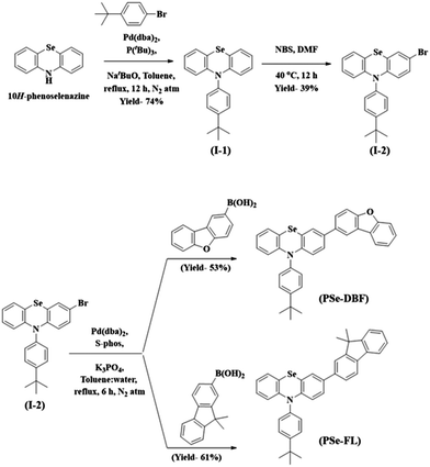
The main purpose of this study was to examine the effect of substituents attached to the PSe core on the RTP properties of PSe core-based PO-RTP emitters. We used PSe as an aromatic core unit of our design since the heavy atom effect of the Se atom has been extensively proven to trigger RTP emission.31–34 The PSe core was modified with dibenzo[b,d]furan (DBF) unit and a 9,9-dimethyl-9H-fluorene (FL) unit. Furthermore, the PSe core of both phosphors was N-substituted with a 4-tert-butylphenyl substituent to control the intermolecular interactions.Scheme 1 shows the synthetic pathway for the target materials. The PSe core was synthesized using the method described in our previous paper.35 The PSe core was N-arylated with 1-bromo-4-(tert-butyl)benzene to form 10-(4-(tert-butyl)phenyl)-10H-phenoselenazine (I-1) in 74% yield. The I-1 was brominated at 40 °C using N-bromo succinimide in N,N-dimethyl formamide to produce 3-bromo-10-(4-(tert-butyl)phenyl)-10H-phenoselenazine (I-2). Finally, under Suzuki coupling conditions, the I-2 was treated with dibenzo[b,d]furan-2-ylboronic acid and (9,9-dimethyl-9H-fluoren-2-yl)boronic acid to obtain PSeDBF and PSeFL, respectively, in moderate yield. Column chromatography is used to purify the synthesized intermediates and final compounds. Highly pure PSeDBF and PSeFL were obtained via vacuum sublimation of the final compounds. Mass spectrometry, high-resolution mass spectrometer, and proton and carbon nuclear magnetic resonance spectroscopy (1H and 13C-NMR) were used to confirm the structure of intermediate and final compounds.
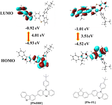
Density functional theory (DFT) calculations using the B3LYP/6-311 + G** basic set of the Gaussian 16 software were used to determine the optimized geometry and highest occupied molecular orbital (HOMO)/lowest unoccupied molecular orbital (LUMO) distributions of the PSeDBF and PSeFL. Fig. 1 shows the frontier orbital distributions of PSeDBF and PSeFL. The HOMOs of PSeDBF and PSeFL are mostly confined within the PSe core and are partially extended across their respective subunits (DBF and FL units) and 4-tert-butylphenyl pendant. The LUMO of PSeDBF was distributed over the DBF unit, whereas that of PSeFL was located over the FL unit and extended significantly over the PSe core. Therefore, the PSeDBF showed limited HOMO–LUMO overlap, whereas the PSeFL showed substantial HOMO–LUMO overlap. Compared with DBF, relatively weak electron deficiency of the FL unit widely extended the PSeFL LUMO.
Additionally, the disparity in the HOMO–LUMO distribution can be partially explained by dihedral angle data. The dihedral angles between the PSe core and subunits in PSeDBF and PSeFL were 38.0° and 35.6°, respectively. The reduced dihedral angle resulted in increased HOMO–LUMO overlapping in PSeFL compared with PSeDBF. PSeDBF and PSeFL had dihedral angles of 97.7° and 90.3° between the PSe core and the p-tert-butylphenyl pendant, respectively. The large twisting and the presence of the tert-butyl group at the 4-position of the phenyl pendant are crucial to disturbing the molecular packing in the solid state to avoid intermolecular interactions.
Experimental HOMO, LUMO, and HOMO–LUMO band gaps were measured using cyclic voltammetry (CV) with a 0.1% tetrabutylammonium perchlorate solution as an internal standard. Fig. S7 (ESI†) shows the CV curves, and Table 1 contains the calculated energy level data. The oxidation curves of the compounds were characterized by multiple oxidation waves caused by the oxidation of the PSe unit. The oxidation of the fluorene unit caused an extra significant oxidation wave at 1.5 V in the PSeFL. The oxidation potential calculated from the first oxidation wave was 0.64 V for both PSeDBF and PSeFL. PSeDBF, however, had a smaller reduction potential than PSeFL (−2.28 V), with a value of −2.38 V. For PSeDBF and PSeFL, the HOMO/LUMO/HOMO–LUMO gap was calculated as −5.44/−2.42/3.02 and −5.44/−2.52/2.91 eV, respectively.
| Emitter | λ abs (nm) | λ em (nm) | E s /ETi/ΔEST (eV) | HOMO/LUMO/BG (eV)j | Φ PL (%) | τ P /τdo (ns/ms) | |
|---|---|---|---|---|---|---|---|
| a Absorption measured in 10−5 M toluene solution. b Emission maximum in 10−5 M toluene solution without N2 purging. c Emission maximum in 10−5 M toluene solution after N2 purging. Emission measured in frozen toluene under N2 at 77 k without 1.0 ms delay. d (LTFL) and with 1.0 ms delay. e (LTPL). Room temperature emission was measured using film prepared by doping 1 wt% emitters in mCP-TSPO1 host film matrix without 1.0 ms delay. f (RTFL) and 1.0 ms delay. g (RTPL). h Calculated from the onset of the first peak of LTFL. i Calculated from the onset of the first peak of LTPL. j Calculated from the cyclic voltammetry analysis. k Photoluminescence quantum yield measured using 1 wt% of the emitter doped in m-CP:TSPO1 host matrix. l Measured under nitrogen atmosphere. m Measured in the absence of a nitrogen atmosphere. n Prompt and. o delayed fluorescence lifetime measured using 1 wt% of the emitter doped in m-CP:TSPO1 host matrix. | |||||||
| PSeDBF | 292 (sh), 314–400 (sh) | 439b/439c/426, 506d/507e | 422,521f/526g | 3.11/2.64/0.47 | −5.44/−2.42/3.02 | 59l/20m | 6.80/0.91 |
| PSeFL | 314, 340–433 (sh) | 452b/451c/429, 529d/530e | 423,526f/542g | 3.13/2.55/0.58 | −5.44/−2.52/2.91 | 40l/10m | 8.29/4.58 |
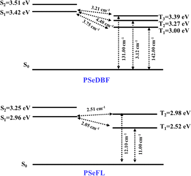
SOCME calculations were performed to understand the possibility of ISC achieving an effective RTP. The SOCMEs, excited state energies, and S1–T1 energy gap (ΔEST) of the PSeDBF and PSeFL phosphors were calculated using time-dependent density functional theory (TD-DFT) calculations based on the B3LYP functional, def2-TZVP basis set, and the ORCA program (Fig. 2 and Table S1, ESI†). The S1 energy of PSeDBF was 3.42 eV, whereas T1, T2, and T3 energies were 3.00, 3.27, and 3.39 eV, respectively, showing that the ISC from S1 to T1, T2, and T3 is plausible. The SOCMEs for the electronic transition were calculated, and those of PSeDBF for the T1 → S0, T2 → S0, and T3 → S0 were 142.00, 3.12, and 131.00 cm−1, respectively. The high SOCME for the T1 → S0 and T3 → S0 suggests that the phosphorescence of PSeDBF would be more efficient. In PSeFL, the S1, T1, and T2 energies were 2.96, 2.52, and 2.98 eV, respectively, and the SOCMEs for T1 → S0 and T2 → S0 were 11.0 and 12.10 cm−1, respectively. The relatively small SOCMEs for phosphorescence suggest inefficient phosphorescence of PSeFL. According to the SOCME data, the PSeDBF may outperform the PSeFL as a pure PO-RTP emitter. The considerable extension of the molecular orbital, which weakens the heavy atom effect, causes the low SOCME values of PSeFL. Thus, the DBF substituent would be preferable to the FL substituent to activate the phosphorescence of the PSe core-based PO-RTP emitters.
Photophysical properties
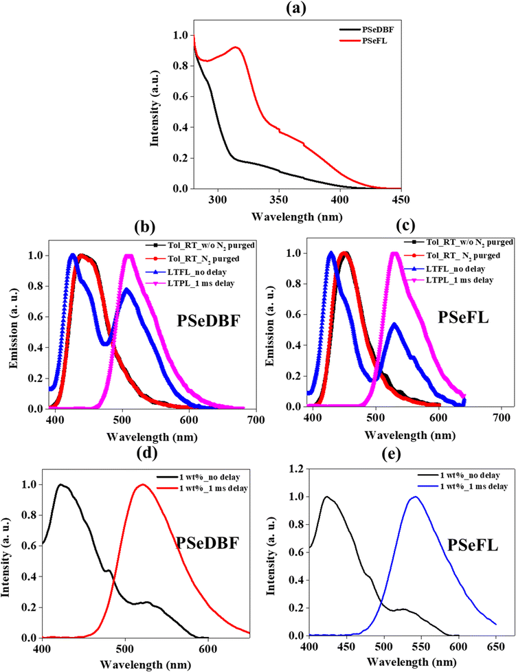
The ultraviolet-visible (UV-vis) absorption spectra of PSeDBF, PSeFL, as well as PSe-core were measured at room temperature in toluene solution (10−5 M). (Fig. 3a and Fig. S7, ESI†). The PSe-core showed a strong absorption peak at 315 nm (Fig. S7, ESI†) which was retained in PSeFL, whereas it appeared as shoulder peak in PSeDBF (Fig. 3a). The UV-vis absorption of PSeFL was redshifted compared to that of PSeDBF by extending conjugation through the FL unit. The absorption peaks below 400 nm were caused by the π–π* and n–π* absorptions. The optical bandgap for PSeDBF and PSeFL was estimated to be 3.06 eV and 2.98 eV, respectively, from the onset energy of UV-vis absorption.The photoluminescence (PL) measurements were conducted using toluene solution (10−5 M) with and without N2 purging at room temperature (Fig. 3b for PSeDBF and Fig. 3c for PSeFL). The low-temperature PL analysis was performed using 10−5 M toluene solution at 77 K without (LTFL) and with 1.0 ms delay (LTPL) time (Fig. 3b for PSeDBF and Fig. 3c for PSeFL). The solid film PL was measured using a film prepared by 1 wt% emitter doping in 1,3-bis(N-carbazolyl)benzene (m-CP)/diphenylphosphine oxide-4-(triphenylsilyl)phenyl (TSPO1) matrix without (RTFL) and with 1.0 ms delay time (RTPL) at room temperature (Fig. 3d for PSeDBF and Fig. 3e for PSeFL). Table 1 shows the data obtained. In addition to that, we also measured PL and LTPL of PSe-core in 10−5 M concentration toluene solution (Fig. S7, ESI†).
The PL spectrum of PSe-core showed strong fluorescence emission with emission maximum at 377 nm. The LTPL spectrum of the PSe-core with 1.0 ms delay showed a strong phosphorescence emission at 488 nm without fluorescence peak. The PL spectra of the PSeDBF and PSeFL in dilute toluene solution were the same with and without N2 purging, showing that the emission is fluorescence. The peak wavelength was 439 nm for PSeDBF and 452 nm for PSeFL without any phosphorescence. This is because of molecular motion in solution dissipation of triplet exciton energy. The phosphorescence was activated in frozen solution. The low-temperature PL (LTPL) in frozen toluene at 77 K measured without 1.0 ms delay (LTFL) was characterized by two emission peaks. In addition to the blue-shifted fluorescence at 426 and 429 nm in PSeDBF and PSeFL, respectively, a second peak at 506 and 529 nm for PSeDBF and PSeFL appeared because of phosphorescence. After applying a 1.0 ms delay (LTPL), the fluorescence peak at 426 and 429 nm for PSeDBF and PSeFL, respectively were disappeared, and only phosphorescence was observed. Nonradiative decay was suppressed by restricted molecular mobility in the compounds, resulting in an intense phosphoresce emission in frozen toluene at 77 K (LTPL). The phosphorescence was from mixed excited state of local and charge transfer states considering the broadened emission spectra with vibrational peaks compared with the phosphorescence of the core structure without the substituents.36
The solid film PL spectra of 1 wt% emitter in m-CP/TSPO1 host matrix without delay showed fluorescence/phosphorescence at 422/521 nm for PSeDBF and 423/526 nm for PSeFL at room temperature. After 1.0 ms delay time, only phosphorescence was observed at 526 and 542 nm for PSeDBF and PSeFL, respectively. The film PL was further investigated by varying the doping concentrations of the emitters in the host matrix from 1 to 15 wt% (Fig. S8 and S9, ESI†). The emission spectra was not changed significantly as the doping concentration of the emitter increased from 1 to 15 wt% for both compounds, suggesting that the emission was from a single molecules. Thus, the solid film PL data confirmed that the synthesized molecules exhibit strong phosphorescence at room temperature.
For the PSeDBF and PSeFL, the PLQYs of a 1 wt% emitter doped mCP-TSPO1 film under nitrogen/under air were 59/20% and 40/10%, respectively. The PLQY of both emitters was dramatically reduced under air, implying that triplet excitons played a significant role in the emission process. The PLQY of PSeDBF was much higher than that of PSeFL, indicating an efficient phosphorescence of PSeDBF, as can be predicted from the high SOCME. The DBF unit played a role in enhancing the PLQY of the PO-RTP emitter as an auxochromophore through a weakly extended molecular orbital. It is anticipated that PSeDBF-based devices will perform better than PSeFL-based devices.
Transient PL (TRPL) analysis was used to investigate the origin of emission of the PSeDBF and PSeFL (Fig. S8, ESI† and Table 1). The TRPL analysis was conducted using a film prepared by doping 1 wt% emitter in the mCP-TSPO1 host matrix. The prompt fluorescence lifetime for PSeDBF and PSeFL was 6.80 and 8.70 ns, respectively. Interestingly, the PSeDBF had a fivefold shorter phosphorescence lifetime than PSeFL. The PSeDBF had a phosphorescence lifetime of 0.91 ms, whereas PSeFL had a phosphorescence lifetime of 4.58 ms. These results unequivocally show the significance of the inclusion of the DBF unit on the PSe core in shortening the excited state lifetime compared with the FL unit. The high SOCME of PSeDBF accelerated the phosphorescence, and the long-excited lifetime supports phosphorescence as the origin of the emission.
Electroluminescence properties
The electroluminescence performance of the compounds was examined by fabricating devices using an mCP/TSPO1 (50![[thin space (1/6-em)]](https://www.rsc.org/images/entities/char_2009.gif) :
:![[thin space (1/6-em)]](https://www.rsc.org/images/entities/char_2009.gif) 50) mixed host system. The triplet energies of mCP and TSPO1 were 2.9 and 3.3 eV, respectively, whereas those of PSeDBF and PSeFL were 2.64 and 2.55 eV, respectively. Triplet excitons can be harvested effectively without back energy transfer from guest to host since the triplet energy of the host system is much higher than that of the guest dopants. The optimized multilayer device structure is indium tin oxide (50 nm)/PEDOT: PSS (60 nm)/TAPC (10 nm)/TCTA (10 nm)/PCzAC (5 nm)/mCP (5 nm)/mCP:TSPO1: dopant (25 nm:50%:5%)/TSPO1 (5 nm)/TPBi (40 nm)/LiF (1 nm)/Al (200 nm), where the mCP:TSPO1:dopant was an emitting layer (EML). The details of the device layers, the optimized device diagram, and the structures of the device layers are provided in the ESI† (Fig. S9). Three devices with different dopant doping concentrations were fabricated. Devices A, B, and C with doping concentrations of 5, 10, and 15 wt% were fabricated for PSeDBF, respectively, and devices D, E, and F with 5, 10, and 15 wt% doping concentrations were fabricated for PSeFL, respectively. Fig. S10 (ESI†) shows the device properties, and Table 2 shows the related data.
50) mixed host system. The triplet energies of mCP and TSPO1 were 2.9 and 3.3 eV, respectively, whereas those of PSeDBF and PSeFL were 2.64 and 2.55 eV, respectively. Triplet excitons can be harvested effectively without back energy transfer from guest to host since the triplet energy of the host system is much higher than that of the guest dopants. The optimized multilayer device structure is indium tin oxide (50 nm)/PEDOT: PSS (60 nm)/TAPC (10 nm)/TCTA (10 nm)/PCzAC (5 nm)/mCP (5 nm)/mCP:TSPO1: dopant (25 nm:50%:5%)/TSPO1 (5 nm)/TPBi (40 nm)/LiF (1 nm)/Al (200 nm), where the mCP:TSPO1:dopant was an emitting layer (EML). The details of the device layers, the optimized device diagram, and the structures of the device layers are provided in the ESI† (Fig. S9). Three devices with different dopant doping concentrations were fabricated. Devices A, B, and C with doping concentrations of 5, 10, and 15 wt% were fabricated for PSeDBF, respectively, and devices D, E, and F with 5, 10, and 15 wt% doping concentrations were fabricated for PSeFL, respectively. Fig. S10 (ESI†) shows the device properties, and Table 2 shows the related data.
| Dopant | Device | Doping conc. (%) | V on (V) | EQEmaxb (%) | PEmaxc (lm W−1) | CEmaxd (cd A−1) | (x, y)e | ELmaxf (nm) |
|---|---|---|---|---|---|---|---|---|
| a Turn on voltage. b Maximum external quantum efficiency. c Maximum power efficiency. d Maximum current efficiency. e CIE color coordinates. f Electroluminescence maximum at 5 V. | ||||||||
| PSeDBF | A | 5 | 3.5 | 11.95 | 30.56 | 42.15 | (0.37, 0.50) | 533 |
| B | 10 | 3.5 | 12.78 | 35.33 | 45.00 | (0.38, 0.49) | 535 | |
| C | 15 | 3.5 | 11.63 | 36.59 | 40.78 | (0.38, 0.49) | 537 | |
| PSeFL | D | 5 | 4.0 | 6.73 | 13.86 | 21.78 | (0.48, 0.43) | 555 |
| E | 10 | 4.0 | 7.43 | 16.64 | 23.85 | (0.48, 0.43) | 555 | |
| F | 15 | 4.0 | 6.03 | 15.00 | 19.11 | (0.47, 0.42) | 558 | |
Because of dopant-assisted direct hole injection in the EML, the turn-on voltage of the devices was reduced by increasing the doping concentration. As expected, all the PSeDBF devices showed EQEmax of greater than 10%, and device B achieved the highest efficiency of 12.78%. The PSeFL-based devices, however, exhibited an EQEmax of over 6%, and the best EQE was 7.43% for device E. The maximum power efficiency (PE) and current efficiency (CE) followed a similar trend. The PEmax values for devices A, B, and C were 30.56, 35.33, and 36.59 lm W−1, respectively, whereas those for devices D, E, and F were 13.86, 16.64, and 15.0 lm W−1, respectively. In contrast to the PSeFL-based device E, which showed a higher CEmax of 23.85 cd A−1, the PSeDBF-based device B reached its maximum CEmax of 45.00 cd A−1. The difference in EQEmax, PEmax, and CEmax between PSeDBF- and PSeFL-based devices demonstrated the PSeDBF developed by incorporating additional DBF units on the Pse core outperformed PSeFL substantially.
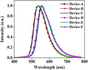
The emission from all the fabricated devices was in the green region. The corresponding CIE color coordinates were found to be (0.37, 0.50), (0.38, 0.49), (0.38, 0.49), (0.48, 0.43), (0.48, 0.43), and (0.47, 0.42) for devices A, B, C, D, E, and F, respectively. The EL emission at 5 V for devices A, B, and C was at 533, 535, and 537 nm, respectively (Fig. 4). The EL maximum at 5 V for the PSeFL-based devices D, E, and F was redshifted to 555, 555, and 557 nm, respectively, compared with PSeDBF devices. This trend was the same as that observed in the PL emission of the materials. However, the EL emission from the devices remained almost the same even after increasing the doping concentrations from 5% to 15%, suggesting that the concentration caused red shift was effectively suppressed in the devices. Furthermore, the EL spectra were free from the fluorescence emission of the compounds, suggesting that the pure-phosphorescence emission is the main emission source in PO-RTP emitters. This is indicative of excellent triplet excitons harvesting in the fabricated PO-RTP devices.
Conclusions
In summary, by substituting the PSe core with two different substituents, two novel Se-based phosphors were developed. In comparison with the PSeFL, which had a PLQY of 40% and a longer excited lifetime of 4.58 ms, the PSeDBF emitter with Se and DBF unit had a higher PLQY of 59% and a shorter excited state lifetime of 0.91 ms. The high SOCME of PSeDBF and the PLQY enhancing function of DBF causes an increase in phosphorescence characteristics. Therefore, the PSeDBF-based devices outperformed the PSeFL devices. The device B, fabricated using 10% PSeDBF, had the highest EQEmax of 12.78% compared with the PSeFL-based device E, with the highest EQEmax of 7.43%. This study shows that it is possible to develop high-efficiency PO-RTP molecules for OLED applications by correctly substituting the PO-RTP core.Conflicts of interest
There are no conflicts to declare.Acknowledgements
This work was supported by the National Research Foundation of Korea (NRF-2020R1A2C2100872).Notes and references
- A. Forni, E. Lucenti, C. Botta and E. Cariati, J. Mater. Chem. C, 2018, 6, 4603–4626 RSC.
- W. Wang, Y. Zhang and W. J. Jin, Coord. Chem. Rev., 2020, 404, 213107 CrossRef CAS.
- L. Xiao, Z. Chen, B. Qu, J. Luo, S. Kong, Q. Gong and J. Kido, Adv. Mater., 2011, 23, 926–952 CrossRef CAS.
- R. Kabe, N. Notsuka, K. Yoshida and C. Adachi, Adv. Mater., 2016, 28, 655–660 CrossRef CAS.
- R. Cui, W. Liu, L. Zhou, X. Zhao, Y. Jiang, Y. Zheng and H. Zhang, J. Mater. Chem. C, 2017, 5, 2066–2073 RSC.
- A. Tomkeviciene, T. Matulaitis, M. Guzauskas, V. Andruleviciene, D. Volyniuk and J. V. Grazulevicius, Org. Electron., 2019, 70, 227–239 CrossRef CAS.
- J. Zhao, W. Wu, J. Sun and S. Guo, Chem. Soc. Rev., 2013, 42, 5323–5351 RSC.
- A. Tomkeviciene, A. Dabulienė, T. Matulaitis, M. Guzauskas, V. Andruleviciene, J. V. Grazulevicius, Y. Yamanaka, Y. Yano and T. Ono, Dyes Pigm., 2019, 170, 107605 CrossRef CAS.
- K. Y. Zhang, Q. Yu, H. Wei, S. Liu, Q. Zhao and W. Huang, Chem. Rev., 2018, 118, 1770–1839 CrossRef CAS PubMed.
- Z. Chai, C. Wang, J. Wang, F. Liu, Y. Xie, Y.-Z. Zhang, J.-R. Li, Q. Li and Z. Li, Chem. Sci., 2017, 8, 8336–8344 RSC.
- H. Chen, X. Yao, X. Ma and H. Tian, Adv. Opt. Mater., 2016, 4, 1397–1401 CrossRef CAS.
- Z. Yang, Z. Mao, X. Zhang, D. Ou, Y. Mu, Y. Zhang, C. Zhao, S. Liu, Z. Chi, J. Xu, Y.-C. Wu, P.-Y. Lu, A. Lien and M. R. Bryce, Angew. Chem., Int. Ed., 2016, 55, 2181–2185 CrossRef CAS PubMed.
- X. Yan, H. Peng, Y. Xiang, J. Wang, L. Yu, Y. Tao, H. Li, W. Huang and R. Chen, Small, 2022, 18, 2104073 CrossRef CAS.
- S. Wang, H. Zhang, B. Zhang, Z. Xie and W.-Y. Wong, Mater. Sci. Eng., R, 2020, 140, 100547 CrossRef.
- L. Xiao and H. Fu, Chem. – Eur. J., 2019, 25, 714–723 CrossRef CAS.
- I. Sánchez-Barragán, J. M. Costa-Fernández, R. Pereiro, A. Sanz-Medel, A. Salinas, A. Segura, A. Fernández-Gutiérrez, A. Ballesteros and J. M. González, Anal. Chem., 2005, 77, 7005–7011 CrossRef PubMed.
- A. S. Carretero, A. S. Castillo and A. F. Gutiérrez, Crit. Rev. Anal. Chem., 2005, 35, 3–14 CrossRef CAS.
- A. Segura-Carretero, C. Cruces-Blanco, B. Cañabate-Díaz, J. F. Fernández-Sánchez and A. Fernández-Gutiérrez, Anal. Chim. Acta, 2000, 417, 19–30 CrossRef CAS.
- D. R. Lee, J. Park and J. Y. Lee, Org. Electron., 2022, 106, 106534 CrossRef CAS.
- W. Z. Yuan, X. Y. Shen, H. Zhao, J. W. Y. Lam, L. Tang, P. Lu, C. Wang, Y. Liu, Z. Wang, Q. Zheng, J. Z. Sun, Y. Ma and B. Z. Tang, J. Phys. Chem. C, 2010, 114, 6090–6099 CrossRef CAS.
- Y. Gong, Y. Tan, H. Li, Y. Zhang, W. Yuan, Y. Zhang, J. Sun and B. Z. Tang, Sci. China: Chem., 2013, 56, 1183–1186 CrossRef CAS.
- M. Singh, K. Liu, S. Qu, H. Ma, H. Shi, Z. An and W. Huang, Adv. Opt. Mater., 2021, 9, 2002197 CrossRef CAS.
- J. Zhu, X. Bai, X. Chen, H. Shao, Y. Zhai, G. Pan, H. Zhang, E. V. Ushakova, Y. Zhang, H. Song and A. L. Rogach, Adv. Opt. Mater., 2019, 7, 1801599 CrossRef.
- C. Feng, S. Li, X. Xiao, Y. Lei, H. Geng, Y. Liao, Q. Liao, J. Yao, Y. Wu and H. Fu, Adv. Opt. Mater., 2019, 7, 1900767 CrossRef CAS.
- Z. An, C. Zheng, Y. Tao, R. Chen, H. Shi, T. Chen, Z. Wang, H. Li, R. Deng, X. Liu and W. Huang, Nat. Mater., 2015, 14, 685–690 CrossRef CAS PubMed.
- J. Yang, X. Gao, Z. Xie, Y. Gong, M. Fang, Q. Peng, Z. Chi and Z. Li, Angew. Chem., Int. Ed., 2017, 56, 15299–15303 CrossRef CAS PubMed.
- Y. Xie, Y. Ge, Q. Peng, C. Li, Q. Li and Z. Li, Adv. Mater., 2017, 29, 1606829 CrossRef PubMed.
- S. Cai, H. Shi, D. Tian, H. Ma, Z. Cheng, Q. Wu, M. Gu, L. Huang, Z. An, Q. Peng and W. Huang, Adv. Funct. Mater., 2018, 28, 1705045 CrossRef.
- Q. Li and Z. Li, Adv. Sci., 2017, 4, 1600484 CrossRef.
- E. Hamzehpoor and D. F. Perepichka, Angew. Chem., Int. Ed., 2020, 59, 9977–9981 CrossRef CAS PubMed.
- D. R. Lee, K. H. Lee, W. Shao, C. L. Kim, J. Kim and J. Y. Lee, Chem. Mater., 2020, 32, 2583–2592 CrossRef CAS.
- D. R. Lee, S. H. Han and J. Y. Lee, J. Mater. Chem. C, 2019, 7, 11500–11506 RSC.
- C. L. Kim, J. Jeong, D. R. Lee, H. J. Jang, S.-T. Kim, M.-H. Baik and J. Y. Lee, J. Phys. Chem. Lett., 2020, 11, 5591–5600 CrossRef CAS PubMed.
- D. de Sa Pereira, D. R. Lee, N. A. Kukhta, K. H. Lee, C. L. Kim, A. S. Batsanov, J. Y. Lee and A. P. Monkman, J. Mater. Chem. C, 2019, 7, 10481–10490 RSC.
- G. Tin, T. Mohamed, N. Gondora, M. A. Beazely and P. P. N. Rao, MedChemComm, 2015, 6, 1930–1941 RSC.
- C. L. Kim, J. Jeong, H. J. Jang, K. H. Lee, S.-T. Kim, M.-H. Baik and J. Y. Lee, J. Mater. Chem. C, 2021, 9, 8233–8238 RSC.
Footnote |
| † Electronic supplementary information (ESI) available. See DOI: https://doi.org/10.1039/d2tc03253h |
| This journal is © The Royal Society of Chemistry 2023 |

