
 Open Access Article
 This Open Access Article is licensed under a Creative Commons Attribution-Non Commercial 3.0 Unported Licence
Ultra-high dispersion of Ni-based OER catalysts on graphene 3D networks enhances the in situ Fe3+ catalytic activation†
María
González-Ingelmo
 a,
Miriam López
García
a,
Freddy E.
Oropeza
b,
Patricia
Álvarez
a,
Clara
Blanco
a,
Ricardo
Santamaría
a and
Victoria G.
Rocha
*a
a,
Miriam López
García
a,
Freddy E.
Oropeza
b,
Patricia
Álvarez
a,
Clara
Blanco
a,
Ricardo
Santamaría
a and
Victoria G.
Rocha
*a
aInstituto de Ciencia y Tecnología del Carbono, INCAR-CSIC, Francisco Pintado Fe 26, 33011 Oviedo, Asturias, Spain. E-mail: vgarciarocha@incar.csic.es
bPhotoactivated Processes Unit, IMDEA Energy, Ramón de la Sagra, 3, 28935 Móstoles, Madrid, Spain
First published on 25th October 2023
Abstract
Hydrogen as an energy carrier plays a significant role in tackling energy transition challenges. Its production via water electrolysis can be powered by renewable sources of energy and it has been identified as the key to a secure and sustainable energy system. Therefore, the development of efficient and abundant electrocatalysts is very important to realize the required large-scale production. In this context, transition metals have been postulated as promising alternatives to noble metal oxides for water splitting in alkaline media. The efficient incorporation of these metals into supports can improve their distribution and particle size control, making carbon supports an ideal choice due to their high conductivity and electrochemical stability. In this work, reduced graphene oxide 3D aerogels doped with very low concentrations of nickel were prepared by freeze-casting. A fully water-based approach that enables an outstanding integration of nickel hydroxide precursor in a colloidal graphene oxide (GO) aqueous suspension was developed. The as-prepared Ni/graphene 3D networks were extensively characterized showing a low loading of nickel (<10 wt%), and ultradispersed, and nanosized Ni-based particles (15–40 nm). Electrochemical experiments show that Ni/graphene 3D networks exhibit very good catalytic properties towards the oxygen evolution reaction (OER) and outstanding Fe-ion activation from the impurities present in the alkaline (KOH 1 M) electrolyte media. Previous studies have shown that Fe incorporation can increase two-fold the activity of Ni-based electrocatalysts. In contrast, the ultradispersed Ni/graphene hybrid prepared here exhibits an impressive over ten-fold performance increase, highlighting the remarkable influence of Fe in these materials. The high-dispersion and surface availability of Ni species promotes the in situ formation of highly active Ni–Fe oxyhydroxide on the surface of the catalysts.
Introduction
Global energy demand has increased during the last few decades driven by population growth and technological advancements. However, since most of this energy comes from fossil fuels, it leads to the release of a significant amount of greenhouse gases that contribute to climate change. Furthermore, fossil fuels are not an unlimited source of energy, and their depletion causes the necessity to develop clean and renewable energy systems that allow progress toward a more sustainable society.1 Within this scenario several alternatives are open, but a promising approach involves the conversion and storage of renewable energy, such as wind or solar energy, into hydrogen. Hydrogen is considered a promising energy carrier due to its high energy density, and it has been proposed as a viable option in addressing key energy transition challenges.Water electrolysis is an alternative approach to hydrogen production that can be easily coupled with renewable energy harvesting because the current technologies, such as photovoltaics and wind turbines output electric power that can be utilized to feed highly efficient electrolyzers. The water electrolysis process consists of two half-reactions, namely, the oxygen evolution reaction (OER) and hydrogen evolution reaction (HER). It is well-known that the OER is the more kinetically demanding step due to the complex process of removing four electrons and four protons from two water molecules with concomitant formation of an O![[double bond, length as m-dash]](https://www.rsc.org/images/entities/char_e001.gif) O double bond (2H2O → O2 + 4H+ + 4e−).2 The state-of-the-art electrocatalysts for this reaction are based on noble metals (Ru or Ir complexes) that provide rapid and efficient oxygen evolution.3 However, the high cost and scarcity of precious electrocatalysts seriously prohibit large-scale application. Thus, it is essential to explore low-cost, earth-abundant, efficient, and stable materials for the realization of clean energy conversion.4 Over the past decade, non-precious transition metal (Ni, Co, Fe, and Mn) catalysts have been studied and shown promising performances. In particular, Ni-based electrocatalyst design has become a hot topic due to its abundance and electrochemical efficiency.5
O double bond (2H2O → O2 + 4H+ + 4e−).2 The state-of-the-art electrocatalysts for this reaction are based on noble metals (Ru or Ir complexes) that provide rapid and efficient oxygen evolution.3 However, the high cost and scarcity of precious electrocatalysts seriously prohibit large-scale application. Thus, it is essential to explore low-cost, earth-abundant, efficient, and stable materials for the realization of clean energy conversion.4 Over the past decade, non-precious transition metal (Ni, Co, Fe, and Mn) catalysts have been studied and shown promising performances. In particular, Ni-based electrocatalyst design has become a hot topic due to its abundance and electrochemical efficiency.5
The overpotential and activity of nickel electrocatalysts are highly dependent on the available surface area and the distribution of species formed during the reaction.6 Several synthesis methods for nickel-based electrocatalysts have been documented in the literature, including hydrothermal synthesis,7 solvothermal synthesis,8 chemical vapor deposition,9 and coprecipitation.10 Regardless of the method, it is highly recommended to use a support material in order to achieve a homogeneous distribution and to control the particle size. The electrocatalytic activity can be either enhanced or reduced depending on the type of support utilized for the deposition or casting of the electrocatalyst. Carbon materials offer an outstanding option for this purpose due to their electrical conductivity, catalytic performance, and their effects improving durability due to their chemical resistance. The enhanced electrochemical properties of Ni-based carbon hybrids have been previously reported. These improvements can be ascribed to the robust bonding, electronic interactions, and synergistic effects between nanocarbon materials and metallic components; as well as the impact that the support has on the morphology and distribution of the catalysts5 if co-synthesized. To date, nickel-based catalysts for the OER have been prepared on various carbon supports by different preparation routes. For example, Ni-based electrocatalysts have been synthesized and supported on carbon cloth by a hydrothermal method11,12 or electrodeposition13 in a single step. Other notable supports include graphene paper,14 carbon nanotubes,15,16 metal–organic framework (MOF) derived graphenes,17,18 N-doped graphene film,19 or even novel graphene structures as graphene nanoribbons.20 A carbon material that emerges as a highly promising candidate is graphene oxide. This material has a significant number of oxygenated groups that serve as anchoring sites for the catalyst. Moreover, graphene oxide can be obtained as an aqueous suspension through a graphite oxidation process (Hummers'21 and/or Tour's22 methods). The aqueous and colloidal nature of this material enables its mixture with water-based precursors, enhancing the sustainability of the preparation process and reinforcing the interaction between the support and catalysts thanks to the chemistry of the oxygenated groups present in graphene oxide that can act as anchoring sites for the catalysts. Its chemical composition combined with its bidimensional structure makes graphene oxide a good candidate for obtaining hybrid structures using water-based chemistry processing. In turn, graphene oxide properties can be easily improved by thermal reduction and/or graphitization.
To optimize the particle distribution and size of Ni-based electrocatalysts over graphene flakes, it is beneficial and effective to create a 3D structure that prevents flakes from agglomerating during the synthesis and drying process. Lately, graphene oxide has been demonstrated as an excellent water-based suspension that can be processed by freezing and thermal annealing in order to obtain complex hierarchical graphene structures with applications in energy and engineering. Some examples are strain sensors, oil absorbers, membranes, catalyst supports, Joule heaters, or their use in energy storage devices (e.g. supercapacitors electrodes).23,24 In addition to the possibility of linking catalysts or catalysts precursors through to the functional groups, graphene oxide suspension hugely benefits from freezing processing. In brief, the graphene network comprises elongated microscopic channels aligned with the direction of ice growth, separated by walls formed through the confined reorganization of GO flakes during the freezing process.25 Thanks to its low density and high elasticity, the produced aerogels are self-standing and present great ability to withstand shrinkage during lyophilization even at very low concentrations (<0.1 wt%), thus helping to keep a low degree of flake agglomeration and available surface area for the catalysts to be distributed.
It is well known that Ni catalyst activity is increased by the presence of Fe, either if it becomes part of the catalyst during material synthesis or through the in situ incorporation of Fe present as an impurity in alkaline electrolytes. The enhanced OER activity achieved by Fe incorporation during the synthesis of the material is clearly shown by the work conducted by Mu et al. Their fabrication of NiFe/Fe-MoO2 displayed much better OER activity than Ni/MoO2 with overpotential values of 213 mV and 289 mV at 20 mA cm−2, respectively.26 A similar trend in overpotential is observed when Ni and Ni–Fe are coupled to Ru nanocrystals, resulting in lower overpotentials than those exhibited by RuO2/NF.27 The impact of Fe incorporation can vary depending on the concentration and distribution of Fe within the material, which, in turn, is influenced by the incorporation conditions.28 However, the mechanism of iron incorporation and the active species formed in situ are still under investigation. There is no consensus on how Fe incorporation influences the local chemical environment and thus the OER performance.29 Numerous studies have employed electrodeposited Ni(OH)2 films as working electrodes to conduct characterization studies about the dynamic changes in Ni-phases and the incorporation of Fe from the electrolyte using in situ spectroscopic techniques.30–32 It has been shown that the presence of Fe on the surface is essential to achieve species with enhanced activity. However, it has also been described that as the catalysis process progresses, the dissolution of nickel and redeposition in new areas results in Fe hidden in bulk regions of the particle, becoming a non-active species.33 Furthermore, if higher amounts of Fe are incorporated, the formation and segregation of a new species (FeOOH) cause catalyst deactivation due to its low conductivity.29,32 For this reason, the design and preparation of an optimal material that promotes effective Fe incorporation is necessary to make advances in the knowledge of this process.
Here, we report reduced graphene oxide 3D networks decorated with low-loading, well-distributed and nanosized Ni-based particles prepared via wet-chemistry and freeze-casting processing. Different nickel precursors (nitrates and lactates) are used for comparison purposes and nickel loadings are altered by changing the initial ratio GO/NiOHx precursor. The as-prepared hybrid materials are characterized and their performance in the OER was evaluated. We show that Ni-based catalysts prepared in this way are ideal for an efficient Fe incorporation/activation that leads to a ten-fold performance increase upon Fe incorporation. In contrast, bulk Ni-based catalysts undergo performance improvements up to two times.
Due to the low loading and ultra-dispersion of catalyst nanoparticles on the graphene support, our materials could address some of the challenges in determining what occurs in the catalyst during catalysis facilitating the homogeneous incorporation of Fe. Moreover, the low loading of catalysts in our samples gives rise to a strong correlation with the quantity of Fe impurities in the electrolyte.
Therefore, during the activation process in our samples, more Ni atoms will reach the optimal species along with Fe. Consequently, the signal would be clearer in in situ characterization due to the minor presence of non-active species, enriching the sample with the phase of interest. These data would be of great importance in elucidating the structure with enhanced activity and the mechanism by which it forms, thus providing a foundation for the design of more active catalysts.
Materials and methods
Material
Graphite was supplied by MIDEGASA. Nickel nitrate·6H2O (>97%) from Sigma-Aldrich and nickel(II) lactate·4H2O (>98%) from Alfa Aesar were used as nickel particle precursors. 99.9 wt% NiO and 98 wt% Ni(OH)2 from Sigma-Aldrich were used as XPS references. All other chemicals were purchased from Sigma-Aldrich and used as received without any further purification except KOH; its purification process is provided in the ESI.†Synthesis of large flake graphene oxide by a modified Tour method
Natural graphite flakes were sieved between 300 and 425 μm. 7.5 g of graphite are chemically exfoliated in two steps, firstly the graphite is kept in contact with 360 mL of H2SO4 (98 wt%) up to 18 h in a custom-made 2 L reactor with constant mechanical stirring at 170 rpm (high power helical stirrer). Secondly, 45 g of KMnO4 is added slowly to the reactor in three 15-gram batches and the reactor is cooled down to 10 °C using an ice bath during this exothermic process. Then, the temperature is increased up to 50 °C for 3 h. The final step is to cool down to room temperature and the oxidation is stopped by dropwise addition of 1500 mL of 3 wt% H2O2 solution. The resultant suspension is firstly centrifuged (Sigma 2-16 KL) at 4000 rpm for 10 min to remove acid and salts and then washed with DI water by repeated centrifugations at 4000 rpm and overnight redispersion in doubly distilled water. The workup was carried out until the supernatant water of the centrifuged graphene oxide was close to pH = 6, typically occurring after 16 cycles of washing. An increase in centrifugation times up to 3 hours combined with low temperature (17 °C) allows for proper centrifugation throughout the entire washing process. A couple of low-speed (<1000 rpm) centrifugation cycles were typically performed to remove unexfoliated graphite particles. Four 5-mL aliquots of the resultant GO suspension were frozen in Eppendorf tubes and freeze-dried to evaluate the mass concentration using a 5-digit scale. Approximately 3.5 L of 0.59 wt% of GO were collected which corresponds approximately to complete exfoliation yield.Catalyst precursor preparation
Nickel-based catalyst precursors were initially obtained by a modified Beach et al. solvothermal synthesis.34 Briefly, 4 mL of a (0.5 M Ni(NO3)2)·6H2O are added over 16 mL of DI water and 1 mL of absolute EtOH and magnetically stirred for 30 min in a 25-mL round flask. Subsequently, 1 g of urea (>98%) and 0.4 g of a 25 wt% pluronic F127 are added and the reaction temperature is kept at 80 °C for 9 h in a typical set up of refrigerant and oil bath. The precipitate is centrifuged up to 9000 rpm for 15 min and washed with DI twice. Ni-based catalysts precursors (NiOHx) were in addition synthesized by a simpler and scalable route of pH-assisted precipitation of 17 mM of nickel(II) lactate tetrahydrate C6H10NiO6·4H2O (98%) using 1 M NaOH to adjust the pH to 11.35 The Ni-based gel is centrifuged at 4000 rpm up to 15 min, and then double-washed and centrifuged (9000 rpm, 15 min) in DI water. Finally, both nitrate and lactate Ni precursors (NiOHxN or NiOHxL) were frozen and freeze-dried for 48 hours to obtain a non-agglomerated catalyst precursor.Aerogel preparation
To load the catalyst on the graphene oxide aerogel the corresponding amounts of Ni catalyst precursors were added onto the 0.59 wt% GO original suspension by speed mixing (centrifugal–rotational mixing) (DAC 150.1 FVZ-K Hauschild Engineering) at 2500 rpm up to 10 min. A typical batch to prepare two parallelepiped foams consists of 20 g of 0.59 wt% GO suspension and 6–30 mg of the catalyst precursor. Note that the amount of dry GO on 20 g of 0.59 wt% GO suspension is only 0.118 g. Ratios of GO/(Ni precursors) were 20, 10 and 4. A custom-made directional freeze caster similar to previous work in the field25 combined with a freeze-drying unit (TELSTAR Cryodos -50) was used to produce large (8 × 20 × 30 mm) and ultra-light (8–10 mg cm−3) parallelepipeds of graphene oxide porous networks at a freezing rate of 5 °C min−1 in a double specimen PTFE mould. The frozen foams were freeze-dried for at least 72 h. The catalyst-loaded green aerogels were then carbonized in a tubular furnace up to 650 °C at 5 °C min−1 under a N2 flow (100 mL min−1). The residence time at the final temperature was 60 min. After thermal reduction, mass yield is approximately 25–30% therefore apparent density decreases up to 3 mg cm−1. For comparative purposes, the slurry with GO/NiOHxL ratio of 10 was also processed by the tape casting method to create a film. The tape casting was carried out using an automatic film applicator (ELCOMETER 4340) under a 1000 μm stainless steel blade over 10 mm thick-Teflon substrates, subsequently, vacuum dried at room temperature and carbonized in two steps first at 2 °C min−1 up to 100 °C 1 h dwell and then at 5 °C min−1 up to 650 °C for 1 h.Material characterization
The graphene-catalyst-loaded porous networks were characterized through thermogravimetric analysis (TGA), elemental analysis, inductively coupled plasma mass spectrometry (ICP-MS), X-ray photoelectron spectroscopy (XPS), Raman spectroscopy, scanning electron microscopy (SEM) and transmission electron microscopy (TEM). Elemental analyses were performed on a LECO-CHNS-932 micro-analyser and a LECO-VTF-900 furnace coupled to the micro-analyser. XPS spectra were recorded on a SPECS system operating under a pressure of 10−7 Pa with a monochromatic Al Kα X-ray source (175 W). Data was recorded at pass energies of 50 eV for survey scans, 10 eV for C 1s high resolution scans and 30 eV for Ni 2p high resolution scans. The different species in C 1s were quantified by deconvolution of the corresponding XPS peaks using an analysis procedure that employs a combination of Gaussian and Lorentzian functions and a Shirley baseline using CasaXPS. The spectra were calibrated fixing the Csp2 maximum peak at 284.5 eV. The amount of nickel in the catalysts was determined by ICP-MS (Agilent 7700x). The digestion of samples was performed by an ultrasound-assisted procedure in acidic solutions. 1 mg of sample weighed in a 6-digit scale was added to a 60 mL PFA digestion vessel (Savillex) with 7 mL of digestion solution (HCl 37%, HNO3 65%, and Milli-Q H2O in a 3![[thin space (1/6-em)]](https://www.rsc.org/images/entities/char_2009.gif) :1:3 ratio). The vessel was closed and sonicated for 2 h at 80 °C. After digestion, the sample solution was collected by filtration through a 0.22-μm pore size syringe filter using a 10-mL plastic syringe. The residue was washed with 5 mL of Milli-Q water and the filtrate was diluted to 25 g ± 0.0001 g. The sample solution was transferred into an HDPE screw-top bottle for storage at 4 °C. TGA analysis was conducted using TA Instruments SDT Q600 equipment under an air atmosphere with a 10 °C min−1 rate up to 650 °C. The Raman spectra of thermally reduced (650 °C) hybrids composites were recorded with a Renishaw inVia Qontor confocal Raman microscope (Leica MD2700 × 100) using a 532 nm excitation laser source at a laser power of 1–5 mW. The spectra were collected from 10–3500 cm−1 and an average spectrum was calculated.
:1:3 ratio). The vessel was closed and sonicated for 2 h at 80 °C. After digestion, the sample solution was collected by filtration through a 0.22-μm pore size syringe filter using a 10-mL plastic syringe. The residue was washed with 5 mL of Milli-Q water and the filtrate was diluted to 25 g ± 0.0001 g. The sample solution was transferred into an HDPE screw-top bottle for storage at 4 °C. TGA analysis was conducted using TA Instruments SDT Q600 equipment under an air atmosphere with a 10 °C min−1 rate up to 650 °C. The Raman spectra of thermally reduced (650 °C) hybrids composites were recorded with a Renishaw inVia Qontor confocal Raman microscope (Leica MD2700 × 100) using a 532 nm excitation laser source at a laser power of 1–5 mW. The spectra were collected from 10–3500 cm−1 and an average spectrum was calculated.
Electrochemical tests
Electrodes were prepared as follows: 2000 ppm catalyst inks were prepared using 0.02 wt% Nafion on a 20:80 vol% IPA/H2O as solvent. The mixture was sonicated for 2 h to ensure homogeneous dispersion and subsequently drop-casted onto a graphite disc current collector to form a thin film (0.1 mg cm−2) and study their electrocatalytic behaviour. Electrochemical measurements were carried out in a Teflon home-made three-electrode cell at room temperature and under an inert atmosphere. The cell consisted of the previously prepared electrodes as working electrodes, Ag/AgCl/3.5 M KCl as reference electrode, and a graphite rod as the counter electrode. For OER catalysis evaluation, cyclic voltammetry (CV) at 20 mV s−1 was conducted until consistent data and linear sweep voltammetry (LSV) was acquired between 1.2 and 1.8 V (1 mV s−1). All potential values are referred to the reversible hydrogen electrode (RHE). Stability measurements were conducted by chronopotentiometry at 10 mA cm−2 for 12 h. The catalytic activity is reported as current density in mA cm−2, where cm2 is the geometric exposed area (1 cm2). Additionally, the ECSA values were estimated using double-layer capacitance (Cdl) measured in a non-faradaic potential window and using a general specific capacitance of 0.040 mF cm−2 in KOH 1 M.36 Electrochemical impedance spectroscopy (EIS) measurements were also performed at a potential where the OER was assumed for all samples (1.7 V vs. RHE) to evaluate the charge transfer resistance (Rct). Most of the electrochemical tests were performed in KOH 1 M without previous purification. For the high Fe uptake study, KOH 1 M was purified following the method described in the ESI† and KOH 1 M not purified with controlled addition of Fe (FeCl3) were used.
Results and discussion
Processing Ni-based catalysts on graphene 3D networks
Graphene networks as a support for sustainable catalysts based on nickel have been obtained by combining wet chemistry of nickel precursors, freeze casting/drying of graphene oxide suspensions loaded with nickel precursors and thermal reduction at 650 °C in an inert atmosphere. By means of a modified Tour method,22 the chemical exfoliation of large flake size natural graphite (300–425 μm) enabled highly concentrated GO suspension of 0.59 wt% ready to freeze cast without any additive. The graphene oxide (GO) colloidal suspension showed in turn large flake size (avg. 36 μm, Fig. S1a†), high viscosity and high degree of oxidation (C/O ratio of 1.02 by elemental analysis and XPS spectra Fig. S1b†). These specific characteristics of our GO suspension are crucial to achieving two key goals towards ultra-dispersed catalysts. Firstly, the high content and variety of oxidized functional groups enable a perfect colloidal suspension ready to interact with the nickel hydroxides (NiOHx) obtained either by a time-consuming and specific solvothermal synthesis from nitrates (NiOHxN) or a simple and scalable pH-assisted precipitation from lactates (NiOHxL). Secondly, the high concentration and high viscosity due to the large flake size of the suspension allow strong lightweight graphene networks (3 mg cm−3 after thermal reduction, Fig. 1a) by freeze casting without the need for any binder or additive, thus simplifying the water-based processing route.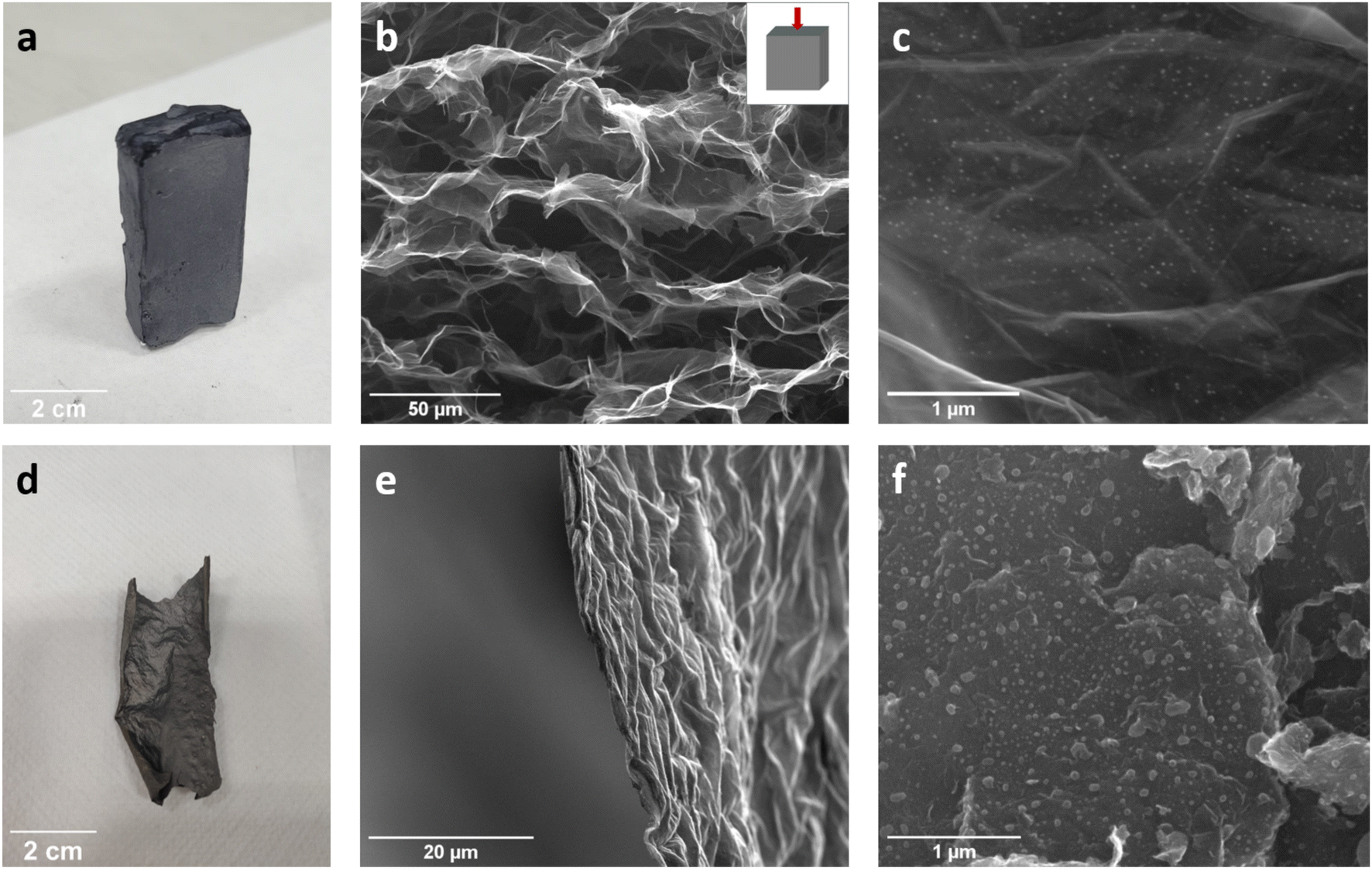 | ||
| Fig. 1 Processing method comparison in rGO-4.1-Ni-lactate. Freeze-casting: (a) macroscopic aspects of the aerogel. Scanning electron micrographs of the Ni-doped rGO networks (taken using electro-dispersive electrons). Image (b) was taken in a perpendicular plane to the direction of ice growth and (c) shows Ni-doped graphene flake at higher magnification. Tape-casting: (d) macroscopic aspects of the film. SEM images show the edge of the film (e) and the dispersion of Ni-based particles (f). | ||
The formulation to load the GO suspension with NiOHx precursors was designed in order to load the 3D network with nanoparticles of catalysts while avoiding the chances of agglomeration and maximizing the functionalized group availability as key for interactions with the catalysts precursors that also show mainly OH groups on their composition (Fig. S2a†). Despite the same GO/NiOHx ratios being chosen for lactates and nitrates, the slightly different weight loss with temperature (Fig. S2b†) of the precursors causes leading to different Ni mass loading in the reduced hybrid materials ranging from 2.5 to 10.3 wt% Ni determined by ICP-MS (Table S1†). Thereafter, the obtained samples were labelled rGO-X-Ni-nitrates or rGO-X-Ni-lactates, where X is the concentration (wt%) of nickel.
To show that the processing route is key and beneficial for supporting nickel catalysts on 3D graphene, tape casting processing instead of freeze casting was also carried out thus obtaining a film rather than an aerogel. Among the different ratios, the formulation GO/NiOHx with a ratio of 10 from lactates was chosen for this purpose since the preparation of this precursor is easier compared to the nitrate route. The macro and microscopic structure of the sample rGO-4.1-Ni-lactates prepared by the two processing methods after thermal reduction at 650 °C are shown in Fig. 1.
While freeze-casting processing leads to hierarchical porous structures/networks (Fig. 1 and b), tape-casting delivers a film (Fig. 1d and e). As can be seen in the SEM image (Fig. 1b), 27 ± 4 μm parallel porous channels resemble the directional ice growth direction during freezing. Further magnification enables to distinguish the homogeneous distribution of nanoparticles achieved by this method (Fig. 1c). The ultra-dispersion of nanoparticles is achieved thanks to the similar chemistry between GO and NiOHx precursors and to the development of a highly porous interconnected graphene network during freezing. The open structure with graphene flakes well-separated prevents particle aggregation. However, tape-casting as a processing method does not prevent the graphene flakes from re-stacking creating more compact and dense structures (Fig. 1e) that result in the formation of nickel particle clusters over the film (Fig. 1f).
Ultradispersion of Ni nanoparticles over graphene 3D networks
The tape-casting nickel particles are notably larger than those in the aerogels. These findings emphasize the benefits regarding particle size and distribution obtained by wet chemistry and freeze-casting as processing techniques for supporting electrocatalysts on 3D networks of graphene. SEM images of the freeze-casted samples with the same ratio GO/NiOHxN are also shown in Fig. S3.† Similar hierarchical networks and Ni-based nanoparticle distribution were achieved by using nickel nitrate as a precursor.TEM images of the thermally reduced graphene flakes loaded with different contents of Ni-based nanoparticles from lactates are shown in Fig. 2. The low-loading sample, rGO-2.5-Ni-lactates, shows 600 nm agglomerates of very small and scattered nanoparticles with an average size of 37 nm (Fig. 2a), while a higher Ni-based loading sample, rGO-4.1-Ni-lactates, shows a homogeneous distribution of smaller nanoparticles (avg. 27 nm) (Fig. 2b). In Fig. 2c, a 30 nm nanoparticle wrapped in a graphene sheet and a bunch of tiny nanoparticles embedded within the graphene layers can be observed. Using lactate as a precursor resulted in nickel particles that are dispersed throughout the graphene flake and have a rounded shape. The d-spacing calculated from SAED analysis (Table S2†) in both samples does not allow to fully disclose whether the nanoparticles' crystalline phases correspond to Ni or NiO. The very low loading of particles also makes it difficult to acquire an XRD pattern.
 | ||
| Fig. 2 TEM images of rGO-2.5-Ni-lactates (a) and rGO-4.1-Ni-lactates (b). In (c), a particle at further magnification is shown with the corresponding selected area electron diffraction (SAED) pattern exhibiting two diffraction rings of 0.211 nm and 0.122 nm (inset c). | ||
Different Ni mass loadings of rGO-Ni from nitrates are also clearly seen by TEM in Fig. 3a (3.8%) and Fig. 3b (6.9%). In contrast with the hybrids prepared from the lactates route, the nanoparticles seem to preferentially locate at the graphene wrinkles and exhibit rod shape. The selective attachment to the edge surfaces and defect sites could be due to the higher reactivity of these areas.37 The particle size image analysis does show an average size of 15 nm for the low-loading sample and 33 nm for the higher one. Despite the differences in morphology and distribution, the d-spacing calculated for these samples is also inconclusive as to whether the nanoparticles are crystalline phases of Ni or NiO (Table S2†).
 | ||
| Fig. 3 TEM images of rGO-3.8-Ni-nitrates (a) and rGO-6.9-Ni-nitrates (b). In (c), Ni-based particles of higher loading samples at further magnification are shown. Inset c exhibits a particle with the corresponding selected area electron diffraction (SAED) pattern exhibiting two diffraction rings of 0.205 nm and 0.119 nm. | ||
The chemical surface states of the hybrid networks were studied by XPS to analyze the composition of the nickel-based particle surface. The spectra of Ni 2p3/2 confirm the presence of oxidized nickel species (Fig. 4) in both precursor samples. Their presence rather than metallic Ni agrees with the reduction of carbon at 650 °C whose XPS spectrum still shows oxygenated functionalities (Fig. S4†). This behavior is due to the high oxidation degree of the starting graphene oxide slurry and the hydroxyl groups introduced by the nickel precursor. Based on the peak intensities and corresponding sensitivity factors, the surface Ni/C ratios were estimated. The obtained values are shown in Table S3†. The amount of nickel on the surface of the hybrid materials seems to be less than the obtained by ICP-MS, possibly because carbon is coating the nanoparticles.
 | ||
| Fig. 4 Ni 2p3/2 XPS analysis of samples according to the precursor: nitrates (a) and lactates (b). NiO and Ni(OH)2 spectra are shown as references. | ||
Fig. 4a shows the XPS of rGO-X-Ni-nitrates samples in the Ni 2p3/2 region along with spectra of NiO and Ni(OH)2 reference samples. Despite the relatively lower signal-to-noise ratio, the three characteristic spectroscopic features present in the NiO's spectrum (a, b and c) can be clearly observed in the Ni 2p peak of both samples. Similarly, Fig. 4b shows XPS of rGO-X-Ni-lactate samples in the Ni 2p3/2 region along with reference spectra. Again, the spectroscopic features characteristic of NiO can be observed, suggesting therefore that Ni is present in the form of the oxide. However, the intensity of feature a relative to b and c is lower in sample rGO-4.1-Ni-lactates. Since the spectrum of Ni(OH)2 only has spectroscopic features b and c (not in the region of a), the spectrum profile of sample rGO-4.1-Ni-lactates suggests a significant contribution from hydroxide species.
As a result, it can be concluded that graphene aerogels with very low nanoparticle catalyst loadings from 2.5 wt% up to 10.3 wt% were successfully prepared by the wet-chemistry, freeze casting and thermal reduction route. The expected advantages in terms of distribution and particle size with this method enable the preparation of active aerogels with much lower loadings compared to previous studies. Indeed, we achieved the ultra-dispersed and nanosized particles, therefore expecting a great enhancement of their catalytic activity.
Electrochemical behaviour of supported catalysts
| Ni(OH)2 + OH− ↔ NiOOH + H2O + e− |
According to this reaction, the anodic peak (positive current density) at around 1.44 V is attributed to the oxidation of Ni(OH)2 to NiOOH, while the cathodic peak (negative current density) at around 1.33 V is related to the reverse reduction process. At higher potentials (>1.55 V vs. RHE), an exponential increase in the current was observed with an increase in the potential, revealing O2 formation from water oxidation.
Fig. 5 displays the OER polarization curves obtained from LSV experiments after the activation method (CP12h @ 10 mA cm−2) for lactates (a) or nitrates (b). Each plot shows the results for two different Ni loadings. Regardless of the precursor used, as the nickel concentration on the carbon network increases, the catalyst activity also increases and the overpotential necessary to reach 10 mA cm−2 decreases (Table 1). In this way, it can be observed how samples with higher Ni contents: rGO-4.1-Ni-lactates and rGO-6.9-Ni-nitrates show better activity, reaching greater current density intensities than the samples with lower Ni concentrations.
 | ||
| Fig. 5 The OER polarization curves of catalysts prepared from nickel nitrate and lactate. The OER polarization curves of hybrid materials prepared using nickel precursor: lactates (a) and nitrates (b) in N2-saturated 1 M KOH at 1 mV s−1. | ||
| Lactates | Nitrates | |||
|---|---|---|---|---|
| Ni (wt%) on the foam | 2.5 | 4.1 | 3.8 | 6.9 |
| Overpotential @ 10 mA cm−2 (mV) | 457 | 432 | 458 | 431 |
| μg Ni on the electrode | 2 | 3.28 | 3.04 | 5.52 |
The importance of catalyst concentration is also evident in other studies where the catalyst concentration is higher than that used in this work. Table S4† presents a comparison among different Ni-based catalysts supported on carbon materials reported in the literature, emphasizing the mass loading of the catalyst on the electrode in each of the studies. Different overpotentials are reported to achieve 10 mA cm−2 depending on the sample composition and nickel concentration. For instance, Ni/NiO@rGO, a sample prepared through chemical synthesis, exhibits an overpotential of 480 mV, which is higher than that found in this work, with a higher catalyst loading on carbon (42%).38 In other studies, various methods for preparing Ni catalysts on reduced graphene oxide were investigated, revealing overpotentials ranging from 390 to 570 mV. The best overpotential was obtained through hydrothermal synthesis using not only Ni but also the Ni–Fe catalyst, with a 70 wt% catalyst loading on carbon.39,40 Another bimetallic catalyst supported on carbon nanorribons, CoNi/GNR, shows an overpotential of 430 mV also with a higher catalyst concentration related to carbon than our samples (40 wt%).41 The same carbon support, graphene nanoribbons, was mixed with nickel pyrophosphate to develop a new hybrid catalyst (GNiPy350N) with lower overpotential (320 mV) and 30 wt% of Ni related to carbon.42 There are also other studies where different ratios of catalyst/carbon are compared showing that the amount of catalyst plays a key role in the activity. For example, Ni0.9Fe0.1/NC overpotentials decrease from 400 to 300 mV when the ratio of catalyst/carbon increases from 20 to 80 wt%.43 Another study prepared Ni-based particles supported on graphene aerogels by a hydrothermal method showing a wide range of overpotentials as the amount of catalyst relative to carbon increases from 1 to 40 wt%.44
The samples prepared in this study exhibit overpotentials that are not only consistent but also better than those reported in the literature, considering the catalyst loading relative to carbon. If the samples prepared with nitrates or lactates are compared, it becomes evident that comparable outcomes were achieved. Nevertheless, when considering the amount of Ni in the electrode as calculated using the ICP values and the drop-casting conditions (40 μL 2000 ppm), it becomes evident that the lactate precursor yields the same overpotential with a lower Ni content.
This fact combined with the simplicity of the pH-assisted precipitation method for the lactate route, makes nickel lactate a better candidate than the nitrate precursor for the preparation of active Ni-supported electrocatalysts. Consequently, the lactate route was selected as the most appropriate option, and further experiments were conducted using it.
 | ||
| Fig. 6 OER electrocatalytic experiments. OER polarization curves (1 mV s−1) of rGO-4.1-Ni-lactates processed by freeze-casting and tape-casting (a), OER activity comparison between rGO-4.1-Ni-lactates and IrO2 as a reference electrode (b) and chronopotentiometry experiments of rGO-4.1-Ni-lactates and IrO2 at 10 mA cm−2 for 6 hours (c). All the experiments were carried out in N2-saturated 1 M KOH. | ||
 | ||
| Fig. 7 OER electrocatalytic experiments. OER polarization curves (1 mV s−1) of rGO (yellow) and rGO loaded with different Ni concentrations: 2.5 wt% (red), 4.1 wt% (blue) and 10.3 wt% (green). | ||
As can be seen in Fig. 7, rGO is not an active OER catalyst reaching a poor current density even at high potentials due to the carbon oxidation reaction rather than the anodic water splitting reaction. Significant differences are observed in samples loaded with 4.1 and 10.3 wt% of Ni (95.3 and 105.7 mV dec−1 Tafel slope values, respectively) and the sample doped with the lowest Ni loading (2.5 wt%) (122.9 mV dec−1). It is also shown that rGO-2.5-Ni-lactates need a higher overpotential to reach 10 mA cm−2 (460 mV) than rGO-4.1-Ni-lactates and rGO-10.3-Ni-lactates (430 mV). Nevertheless, the lack of differences between the samples with the highest amounts of Ni cannot be attributed to a worse distribution of the particles in the material. SEM images of rGO-10.3-Ni-lactates show that nickel particles have a similar distribution to samples with a lower Ni loading (Fig. S10†). Additionally, images of the drop-casted sample on the electrode are also taken. The effective dispersion of the particles continues to be observed and it is confirmed by EDX analysis (Fig. S11†).
TEM analysis was also conducted (Fig. 8) revealing a homogeneous distribution of nanoparticles throughout the graphene flake. Additionally, it is observed that the particles maintain the round shape previously observed with less concentrated lactate samples. Regarding size, it was found that the average size of these Ni-based particles is about 20 nm, smaller than those in the samples rGO-2.5-Ni-lactates and rGO-4.1-lactates. SAED showed that, for the particles analysed, poly-crystalline phases of nickel oxide are clearly identified (Table S6†). It is mentioned as a polycrystalline or defective crystal due to the presence of points instead of well-defined concentric rings in the SAED pattern.
 | ||
| Fig. 8 Characterization of rGO-10.3-Ni-lactates. TEM images at different magnifications (a–d), (d) exhibits a particle with the corresponding SAED pattern (inset) showing diffraction rings that correspond with NiO and XPS deconvolution (e). | ||
Additionally, in Fig. 8b–d, brighter areas can be observed surrounding the particles. These regions could correspond to defects in the graphene layer caused by the reduction of Ni-based particles. The reduction of NiO to metallic nickel in the presence of carbon would oxidize the carbon, leading to the generation of oxidized species that ultimately damage the flake and result in the release of CO and CO2. XPS analysis confirmed that NiO is partially reduced during the synthesis process. The surface of Ni-based particles in the sample rGO-10.3-Ni-lactates clearly evidences the presence of metallic Ni spectroscopic feature, as it is shown with a peak at 852.6 eV in the Ni 2p spectrum (Fig. 8e).
Furthermore, with respect to the carbon oxidation that accompanies nickel reduction, XPS C 1s analysis has revealed a higher level of carbon oxidation in this sample in comparison to the sample without nickel (Fig. S12a†). In this sample, brighter areas in TEM images could indicate that part of the carbon that is oxidized is released as CO and CO2, damaging the graphene flake and modifying the sp2 network, giving rise to the presence of more sp3 configuration as it is confirmed in XPS analysis. Another portion of the oxidized carbon could remain in the structure, resulting in the presence of oxygenated functionalities. In this sense, Raman analysis also confirms that the presence of Ni increases the disorder in the carbon spectrum in comparison to the one without Ni in its composition. A comparison of the Raman spectra obtained from rGO and rGO-10.3-Ni-lactates is presented in Fig. S12b.† It can be observed that the sample without nickel exhibits more resolved peaks with an FWHM value for the ID peak approximately 50 cm−1 lower than the sample with nickel.
In conclusion, the characterization of this sample shows no evidence supporting that rGO-10.3-Ni-lactates do not present a better catalytic activity than samples with lower Ni concentration. Therefore, not finding improvements in the catalytic activity by increasing the nickel loading but keeping ultradispersion and particle size could be related to the well-known influence of Fe impurities in the electrolyte. Our finding is that in these samples where Ni loading is very low but extremely well distributed over the graphene flake, the presence of Fe in the KOH 1 M has a remarkable influence on OER activity and could act as a limiting factor for the activation of the nickel catalysts, thus opening up an excellent processing route to prepare hybrid electrocatalysts for fundamental studies for in-operando analysis.
Despite the difficulty in analyzing these post-catalysis samples due to the low mass loading on the electrode and nickel concentration in the samples, the characterization of the rGO-4.1-Ni-lactate sample is shown (see Fig. S13†). STEM/TEM analysis of the sample reveals that the graphene flakes undergo modifications during catalysis, partially covering the particles and giving them a more wrinkled appearance. This fact hinders the FFT analysis of high-resolution samples, as it yields values that could correspond to both rGO and Ni, making it impossible to draw conclusions about the Ni species using this method. On the other hand, EDX analysis shows the presence of Fe in the particles. This Fe presence in the sample aligns with its incorporation from electrolyte impurities, and it is further confirmed by HR-XPS analysis. XPS analysis demonstrates that the nickel species post-catalysis are more oxidized, consistent with the previously reported nickel aging, which results in active Ni(OH)2/NiOOH mixtures.30,46 The presence of Fe at the expected concentrations is difficult to estimate using HR-XPS, partly due to the overlap of the nickel Auger band within the Fe spectrum range. However, by comparing the signal obtained in the 700–740 eV range, it can be observed that in the case of the pre-catalysis sample, a spectrum compatible with a Fe 2p band is not observed. On the other hand, after catalysis, a spectrum consistent with a Fe 2p spectrum can be detected. Peaks are observed that may correspond to those characteristics of Fe3+ (Fe 2p3/2 at 711.3 eV and Fe 2p1/2 at 724.3 eV).47,48
For example, previous studies indicated that the in situ Fe incorporation into the Ni(OH)2 film or Ni foil during conditioning methods in electrolytes containing Fe impurities gives rise two-fold increase in current density.33,49 In another study, a slightly more significant improvement in activity (3.5-fold) was demonstrated for an electro-deposited Ni film after 200 CVs.50 To verify if this enhancement is of the same magnitude for our cell and conditions, a drop-casted Ni(OH)2 film is tested. In this case, the improvement after the conditioning method is of 3.4 times (from 10 to 34 mA cm−2 at 1.8 V vs. RHE) (Fig. S14a†). Interestingly, our materials undergo a tenfold increase in current density after CP (LSVs before and after CP of rGO-4.1-Ni-lactates are shown in Fig. S14b†). These results confirm that the activation is especially remarkable in our highly dispersed material in comparison to other Ni-based systems. The ultradispersion and small size of nickel particles in the graphene aerogel achieved by our freeze-casting processing facilitate the Fe incorporation that occurs preferentially in the edges. Moreover, the very low concentration of Ni in our samples could be key to the exceptionally significant influence that Fe has in the increased activity. This is due to the amount of Ni drop-casted in the electrode and Fe impurities matching in terms of concentration. This condition has not been previously reported in other studies when a film of Ni(OH)2 is electrodeposited. The low concentration of nickel in our samples makes the quantity of Ni in the electrode even lower than the Fe impurities in the electrolyte. A few calculations to evidence this are KOH 1 M made from ACS reagent-grade KOH flakes (0.001% Fe) are estimated to contain ≤0.56 ppm Fe, so in the volume used for electrochemical experiments (20 mL) it would be 11.2 μg. In this work, the amount of Ni deposited on the working electrode varies between the different samples but the maximum is 8 μg.
Considering that the proportion of Ni present on the electrode and Fe impurities in the electrolyte are of the same order of magnitude, along with the important role that Fe plays in OER catalysis, it is hypothesized that the quantity of Fe may potentially act as a limiting factor when comparing the catalytic activity of our samples. In this way, Fe impurities concentration would not allow all Ni-based particles to reach the optimum ratio of Ni–Fe, and this could become evident when a higher concentration of nickel was tested. This strong correlation between Ni in the electrode and Fe in the electrolyte makes this material especially sensitive to trace amounts of Fe. Therefore, it is an ideal material to study the phenomenon of Fe incorporation and the mechanism by which Ni catalysts are activated.
This hypothesis could explain why no differences are observed among the samples with higher concentrations of nickel (rGO-4.1-Ni-lactates and rGO-10.3-Ni-lactates). According to this, if the concentration of Fe was a limiting factor, the addition of more Fe ions in the electrolyte could allow differences between the two samples to be observed. To confirm this, experiments with higher concentrations of Fe in the electrolyte were carried out. In order to achieve a known concentration of Fe in KOH, it would be ideal to start with Fe-purified KOH. This would enable precise control over the addition of Fe to regulate its concentration. However, Fe-purified KOH obtained through the method described in the ESI† exhibits higher Ni contamination than the original KOH. After 12 hours, when KOH Fe-free is used as an electrolyte, Ni redox peaks appear in CV experiments of the rGO sample (Fig. S15†). These results show that the Fe purification method leaves Ni contamination, which becomes evident in the samples during electrochemical experiments. This Ni contamination has been already previously reported with values of about 400 ppb of Ni in Fe-free KOH electrolytes purified following the same method.51 The addition of Fe in an electrolyte that contains Ni would be notably significant in terms of the interaction that these two materials could have and its effect on catalysis.
Given the impossibility of obtaining Ni- and Fe-free KOH, the alternative approach is to add Fe to the unpurified electrolyte. Therefore, 5 μM Fe3+ ions are intentionally added using FeCl3 to KOH 1 M solution previously purged with N2 gas for at least 20 min to prevent precipitation of insoluble FeOOH.30 It is reported that after Fe-spiking there is an immediate increase in activity, occurring the highest improvement during the first cycles.31 For that reason, in this case, the OER activity of samples in KOH with Fe-added is compared after 20 cycles by linear sweep voltammetry (Fig. 9).
 | ||
| Fig. 9 OER electrocatalytic experiments in KOH with Fe-added. Comparison of the electrocatalytic behavior of the samples in KOH 1 M with μM Fe3+ ions intentionally added after 20 CV experiments (1.2–1.8 V at 50 mV s−1). The LSV experiments were carried out in N2-saturated at 1 mV s−1. | ||
The results show that there is an immediate increase in activity when FeCl3 5 μM is spiked into the alkaline solution, observing as good activities as those obtained after much longer experiments (CP 12 h) in KOH 1 M without Fe added. In the case of rGO-4.1-Ni-lactates, it could be seen that the current density reached after 20 cycles in the Fe-spiked electrolyte is similar to the one obtained after the long activation method by CP experiments (Fig. 7, blue line). This faster activation of the sample could be related to the easier incorporation of Fe over the Ni phase when Fe is added to the electrolyte. However, not finding an improvement in the catalysis (about 50 mA cm−2 @ 1.8 V for both electrolytes, with and without Fe added) means that the activity of this catalyst was not really limited by the Fe concentration. However, in the case of the other sample (rGO-10.3-Ni-lactates, Fig. 9, green line), not only there is an immediate increase in activity after the addition of Fe, but also improved results are obtained in comparison to after CP in KOH without added Fe (Fig. 7, green line). The Tafel slope value of this sample improves from 105.7 to 67.6 mV dec−1 after the addition of Fe. This change in the Tafel value indicates a higher reaction rate which implies greater activity. These findings are consistent with the proposed hypothesis. In the case of the sample with a higher amount of Ni, the Fe impurities present in the electrolyte may not be sufficient to achieve the optimal Ni/Fe ratio which leads to enhanced OER activity.
Conclusions
A novel water-based processing route has been developed as an easy to scale up and efficient method to achieve ultradispersed Ni-based nanoparticle catalysts supported on graphene networks. These routes can be easily implemented to achieve novel catalysts based on sustainable and earth abundant materials. Electrochemical results show good activity in terms of overpotential and Tafel slope according to the nickel mass loading. Moreover, a remarkable influence of Fe impurities was found in these catalysts in comparison to other Ni-based materials. In the quest to synthesize efficient electrocatalysts for the OER, we demonstrate that we can develop materials highly sensitive to the surface changes occurring during catalysis, thus making them ideal hybrid electrocatalysts for fundamental studies for in-operando analysis.Author contributions
María González Ingelmo: investigation, conceptualization, methodology, validation, formal analysis, writing-original draft, writing-review & editing. Miriam López García: graphene oxide characterization by optical microscopy, validation. F. E. Oropeza analysis and interpretation of XPS measurements, writing-review. Patricia Alvarez: supervision, funding acquisition. Ricardo Santamaría: conceptualization, funding acquisition, supervision, writing-review & editing. Clara Blanco: conceptualization, writing-review & editing, funding acquisition. Victoria G. Rocha: investigation, conceptualization, methodology, validation, formal analysis, writing-original draft, writing-review & editing, supervision, funding acquisition.Conflicts of interest
There are no conflicts to declare.Acknowledgements
The authors would like to acknowledge the support from the Spanish Research Agency AEI/PID2019-104028RB-100 and financial support from the Principado de Asturias (FICYT)-European Union (FEDER) (Project PCTI-Asturias IDI/2021/000015). M. González-Ingelmo acknowledges her fellowship from the Asturias regional Government (FICYT, Severo Ochoa Program BP20-168). M. López García also acknowledges her fellowship (PRE2020-095966). V. G. Rocha would like to thank the Spanish Government (Ramón y Cajal fellowship RYC2018-024404-I). F. E. Oropeza thanks MINECO and European NextGenerationEU/PRTR Fund for the Ramón y Cajal contract (RyC2021-034254-I).References
- P. J. Megia, A. J. Vizcaino, J. A. Calles and A. Carrero, Energy Fuels, 2021, 35, 16403–16415 CrossRef CAS.
- J. Hou, Y. Wu, B. Zhang, S. Cao, Z. Li and L. Sun, Adv. Funct. Mater., 2019, 29, 1808367 CrossRef.
- B. Sánchez-Page, A. M. Pérez-Mas, M. González-Ingelmo, L. Fernández, Z. González, M. V. Jiménez, J. J. Pérez-Torrente, J. Blasco, G. Subías, P. Álvarez, M. Granda and R. Menéndez, J. Organomet. Chem., 2020, 919, 121334 CrossRef.
- H. Bai, D. Chen, Q. Ma, R. Qin, H. Xu, Y. Zhao, J. Chen and S. Mu, Electrochem. Energy Rev., 2022, 5(suppl. 2), 24 CrossRef CAS.
- Y. Li, X. Bao, D. Chen, Z. Wang, N. Dewangan, M. Li, Z. Xu, J. Wang, S. Kawi and Q. Zhong, ChemCatChem, 2019, 11, 5913–5928 CrossRef CAS.
- V. Vij, S. Sultan, A. M. Harzandi, A. Meena, J. N. Tiwari, W. G. Lee, T. Yoon and K. S. Kim, ACS Catal., 2017, 7, 7196–7225 CrossRef CAS.
- H. Huang, H. Jung, H. Jun, D. Y. Woo, J. W. Han and J. Lee, Chem. Eng. J., 2021, 405, 126977 CrossRef CAS.
- Z. Wang, J. Li, X. Tian, X. Wang, Y. Yu, K. A. Owusu, L. He and L. Mai, ACS Appl. Mater. Interfaces, 2016, 8, 19386–19392 CrossRef CAS PubMed.
- Y. Cao, Q. Su, R. Che, G. Du and B. Xu, Synth. Met., 2012, 162, 968–973 CrossRef CAS.
- A. Kumar and S. Bhattacharyya, ACS Appl. Mater. Interfaces, 2017, 9, 41906–41915 CrossRef CAS PubMed.
- N. Cheng, Q. Liu, J. Tian, X. Sun, Y. He, S. Zhai and A. M. Asiri, Int. J. Hydrogen Energy, 2015, 40, 9866–9871 CrossRef CAS.
- L. S. Bezerra and G. Maia, J. Mater. Chem. A, 2020, 8, 17691–17705 RSC.
- C. Zhan, Z. Liu, Y. Zhou, M. Guo, X. Zhang, J. Tu, L. Ding and Y. Cao, Nanoscale, 2019, 11, 3193–3199 RSC.
- L. Bruno, M. Scuderi, F. Priolo and S. Mirabella, Sustainable Energy Fuels, 2022, 6, 4498–4505 RSC.
- M. A. Kazakova, D. M. Morales, C. Andronescu, K. Elumeeva, A. G. Selyutin, A. V. Ishchenko, G. V. Golubtsov, S. Dieckhöfer, W. Schuhmann and J. Masa, Catal. Today, 2020, 357, 259–268 CrossRef CAS.
- X. Zhou, Z. Xia, Z. Zhang, Y. Ma and Y. Qu, J. Mater. Chem. A, 2014, 2, 11799–11806 RSC.
- P. Thangasamy, S. Shanmuganathan and V. Subramanian, Nanoscale Adv., 2020, 2, 2073–2079 RSC.
- L. Ai, T. Tian and J. Jiang, ACS Sustain. Chem. Eng., 2017, 5, 4771–4777 CrossRef CAS.
- S. Chen, J. Duan, J. Ran, M. Jaroniec and S. Z. Qiao, Energy Environ. Sci., 2013, 6, 3693–3699 RSC.
- A. S. Souza, L. S. Bezerra, E. S. F. Cardoso, G. V. Fortunato and G. Maia, J. Mater. Chem. A, 2021, 9, 11255–11267 RSC.
- W. S. Hummers and R. E. Offeman, J. Am. Chem. Soc., 1958, 80(6), 1339 CrossRef CAS.
- D. C. Marcano, D. V. Kosynkin, J. M. Berlin, A. Sinitskii, Z. Sun, A. Slesarev, L. B. Alemany, W. Lu and J. M. Tour, ACS Nano, 2010, 4, 4806–4814 CrossRef CAS PubMed.
- N. Ni, S. Barg, E. Garcia-Tunon, F. MacUl Perez, M. Miranda, C. Lu, C. Mattevi and E. Saiz, Sci. Rep., 2015, 5, 13712 CrossRef PubMed.
- S. Barg, F. M. Perez, N. Ni, P. Do Vale Pereira, R. C. Maher, E. Garcia-Tuñon, S. Eslava, S. Agnoli, C. Mattevi and E. Saiz, Nat. Commun., 2014, 5, 4328 CrossRef CAS PubMed.
- O. T. Picot, V. G. Rocha, C. Ferraro, N. Ni, E. D’Elia, S. Meille, J. Chevalier, T. Saunders, T. Peijs, M. J. Reece and E. Saiz, Nat. Commun., 2017, 14425 CrossRef CAS PubMed.
- W. Shi, J. Zhu, L. Gong, D. Feng, Q. Ma, J. Yu, H. Tang, Y. Zhao and S. Mu, Small, 2022, 18, 2205683 CrossRef CAS PubMed.
- D. Wu, B. Liu, R. Li, D. Chen, W. Zeng, H. Zhao, Y. Yao, R. Qin, J. Yu, L. Chen, J. Zhang, B. Li and S. Mu, Small, 2023, 19, 2300030 CrossRef CAS PubMed.
- L. Francàs, S. Corby, S. Selim, D. Lee, C. A. Mesa, R. Godin, E. Pastor, I. E. L. Stephens, K. S. Choi and J. R. Durrant, Nat. Commun., 2019, 10, 5208 CrossRef PubMed.
- C. Kuai, C. Xi, A. Hu, Y. Zhang, Z. Xu, D. Nordlund, C. J. Sun, C. A. Cadigan, R. M. Richards, L. Li, C. K. Dong, X. W. Du and F. Lin, J. Am. Chem. Soc., 2021, 143, 18519–18526 CrossRef CAS PubMed.
- L. Trotochaud, S. L. Young, J. K. Ranney and S. W. Boettcher, J. Am. Chem. Soc., 2014, 136, 6744–6753 CrossRef CAS PubMed.
- M. B. Stevens, C. D. M. Trang, L. J. Enman, J. Deng and S. W. Boettcher, J. Am. Chem. Soc., 2017, 139, 11361–11364 CrossRef CAS PubMed.
- D. Friebel, M. W. Louie, M. Bajdich, K. E. Sanwald, Y. Cai, A. M. Wise, M. J. Cheng, D. Sokaras, T. C. Weng, R. Alonso-Mori, R. C. Davis, J. R. Bargar, J. K. Nørskov, A. Nilsson and A. T. Bell, J. Am. Chem. Soc., 2015, 137, 1305–1313 CrossRef CAS PubMed.
- R. Farhat, J. Dhainy and L. I. Halaoui, ACS Catal., 2020, 10, 20–35 CrossRef CAS.
- E. Beach, S. Brown, K. Shqau, M. Mottern, Z. Warchol and P. Morris, Mater. Lett., 2008, 62, 1957–1960 CrossRef CAS.
- L. Zhang, J. C. C. Chan, H. Eckert, G. Helsch, L. P. Hoyer and G. H. Frischat, Chem. Mater., 2003, 15, 2702–2710 CrossRef CAS.
- C. C. L. McCrory, S. Jung, J. C. Peters and T. F. Jaramillo, J. Am. Chem. Soc., 2013, 135, 16977–16987 CrossRef CAS PubMed.
- I. R. M. Kottegoda, N. H. Idris, L. Lu, J. Z. Wang and H. K. Liu, Electrochim. Acta, 2011, 56, 5815–5822 CrossRef CAS.
- S. S. Narwade, S. M. Mali, R. V. Digraskar, V. S. Sapner and B. R. Sathe, Int. J. Hydrogen Energy, 2019, 44, 27001–27009 CrossRef CAS.
- D. Wang, F. Watanabe and W. Zhao, ECS J. Solid State Sci. Technol., 2017, 6, M3049–M3054 CrossRef CAS.
- D. Wang, F. Watanabe and W. Zhao, J. Electrochem. Soc., 2016, 163, F3158–F3163 CrossRef CAS.
- L. S. Bezerra and G. Maia, J. Mater. Chem. A, 2020, 8, 17691–17705 RSC.
- A. S. Souza, L. S. Bezerra, E. S. F. Cardoso, G. V. Fortunato and G. Maia, J. Mater. Chem. A, 2021, 9, 11255–11267 RSC.
- X. Zhang, H. Xu, X. Li, Y. Li, T. Yang and Y. Liang, ACS Catal., 2016, 6, 580–588 CrossRef CAS.
- F. E. Sarac Oztuna, T. Beyazay and U. Unal, J. Phys. Chem. C, 2019, 123, 28131–28141 CrossRef CAS.
- D. Voiry, M. Chhowalla, Y. Gogotsi, N. A. Kotov, Y. Li, R. M. Penner, R. E. Schaak and P. S. Weiss, ACS Nano, 2018, 12, 9635–9638 CrossRef CAS PubMed.
- S. Klaus, Y. Cai, M. W. Louie, L. Trotochaud and A. T. Bell, J. Phys. Chem. C, 2015, 119, 7243–7254 CrossRef CAS.
- W. Guo, D. Li, D. Zhong, S. Chen, G. Hao, G. Liu, J. Li and Q. Zhao, Nanoscale, 2020, 12, 983–990 RSC.
- T. Wang, Z. Jiang, K. H. Chu, D. Wu, B. Wang, H. Sun, H. Y. Yip, T. An, H. Zhao and P. K. Wong, ChemSusChem, 2018, 11, 1365–1373 CrossRef CAS PubMed.
- Y. J. Son, S. Kim, V. Leung, K. Kawashima, J. Noh, K. Kim, R. A. Marquez, O. A. Carrasco-Jaim, L. A. Smith, H. Celio, D. J. Milliron, B. A. Korgel and C. B. Mullins, ACS Catal., 2022, 12, 10384–10399 CrossRef CAS.
- F. Bao, E. Kemppainen, I. Dorbandt, F. Xi, R. Bors, N. Maticiuc, R. Wenisch, R. Bagacki, C. Schary, U. Michalczik, P. Bogdanoff, I. Lauermann, R. Van De Krol, R. Schlatmann and S. Calnan, ACS Catal., 2021, 11, 10537–10552 CrossRef CAS.
- S. Klaus, L. Trotochaud, M. J. Cheng, M. Head-Gordon and A. T. Bell, ChemElectroChem, 2016, 3, 66–73 CrossRef CAS.
Footnote |
| † Electronic supplementary information (ESI) available. See DOI: https://doi.org/10.1039/d3ta04481e |
| This journal is © The Royal Society of Chemistry 2023 |