
 Open Access Article
 This Open Access Article is licensed under a
 Creative Commons Attribution 3.0 Unported Licence
Enhanced localized electron density from PdCu nanoparticle loading on a defective TiO2 support for selective nitrate electroreduction to ammonia†
Haoran
Wu
a,
Heng
Guo
 *ab,
Fengying
Zhang
ab,
Peng
Yang
a,
Jiaxin
Liu
a,
Yuantao
Yang
a,
Zhen-Feng
Huang
c,
Chenyuan
Zhu
d,
Weitao
Wang
d,
Xin
Tu
*d,
Guidong
Yang
e and
Ying
Zhou
*ab
*ab,
Fengying
Zhang
ab,
Peng
Yang
a,
Jiaxin
Liu
a,
Yuantao
Yang
a,
Zhen-Feng
Huang
c,
Chenyuan
Zhu
d,
Weitao
Wang
d,
Xin
Tu
*d,
Guidong
Yang
e and
Ying
Zhou
*ab
aState Key Laboratory of Oil and Gas Reservoir Geology and Exploitation, Southwest Petroleum University, Chengdu, 610500, China. E-mail: heng.guo@swpu.edu.cn; yzhou@swpu.edu.cn
bSchool of New Energy and Materials, Southwest Petroleum University, Chengdu, 610500, China
cKey Laboratory for Green Chemical Technology of Ministry of Education, Collaborative Innovation Centre of Chemical Science and Engineering, School of Chemical Engineering and Technology, Tianjin University, Tianjin 300072, China
dDepartment of Electrical Engineering and Electronics, University of Liverpool, Liverpool L69 3GJ, UK. E-mail: xin.tu@liv.ac.uk
eXJTU-Oxford Joint International Research Laboratory of Catalysis, School of Chemical Engineering and Technology, Xi'an Jiaotong University, Xi'an, 7010049, China
First published on 10th September 2023
Abstract
The electrocatalytic nitrate (NO3−) reduction reaction (NITRR) to synthesize ammonia (NH3) offers a promising method for both pollution abatement and chemical production. However, the sluggish multi-electron/proton-involved steps limit ammonia selectivity and yield. Herein, we loaded PdCu nanoparticles (PdCu NPs) onto defective TiO2 to regulate the localized electron density for selective NH3 synthesis. Our results show a significant increase in NH3 yield and selectivity (112.0 to 322.7 μmol cm−2 h−1 and 34.6 to 80.1%, respectively), induced by the introduction of PdCu NPs. Importantly, in situ and operando investigations combined with density functional theory (DFT) calculations reveal that PdCu NPs enhance the localized electron density at oxygen vacancies. This regulated electron density suppresses N–N coupling and accelerates N–H bonding processes, thus modulating NH3 selectivity. This unique insight based on localized electron density control provides a rational design strategy for metal-defect support catalysts in ammonia production using electrochemical processes.
1. Introduction
Ammonia (NH3) is essential in industry, the military, and the economy.1–3 However, the industrial NH3 synthesis pathway, known as the Haber–Bosh process, is operated on a centralized and large scale at high temperatures and pressures, contributing to 2% of global energy consumption and 1.5–2% of global CO2 emissions. Therefore, there is a high demand to develop cost-effective and sustainable technologies for decentralized NH3 synthesis under mild conditions.4,5 The electrochemical nitrate reduction reaction (NITRR) to ammonia provides a promising way to turn waste into wealth due to the high solubility and weak N–O bond of nitrate (204 kJ mol−1 compared to 941 kJ mol−1 for the N![[triple bond, length as m-dash]](https://www.rsc.org/images/entities/char_e002.gif) N bond).6–15 However, the low ammonia selectivity and limited yield, alone with several competing reactions, hinder the practical applications of NH3 synthesis via the NITRR. For example, the hydrogen evolution reaction (HER), which starts at 0 V vs. RHE (all potential mentioned below is converted to RHE), compared to NH3 at 0.88 V, intensifies with increasing overpotential and suppresses the NITRR to some extent.16 Furthermore, the N2 formation reaction (1.25 V) involves the transformation of five electrons and six protons, making it more favourable in terms of reaction kinetics than NH3, for which the transformation of eight electrons and nine protons is involved.17–19 Therefore, it is critical to reveal the promoting mechanism for the selective NH3 synthesis and to understand the underlying mechanism for N2 generation in order to design efficient catalysts for the NITRR.
N bond).6–15 However, the low ammonia selectivity and limited yield, alone with several competing reactions, hinder the practical applications of NH3 synthesis via the NITRR. For example, the hydrogen evolution reaction (HER), which starts at 0 V vs. RHE (all potential mentioned below is converted to RHE), compared to NH3 at 0.88 V, intensifies with increasing overpotential and suppresses the NITRR to some extent.16 Furthermore, the N2 formation reaction (1.25 V) involves the transformation of five electrons and six protons, making it more favourable in terms of reaction kinetics than NH3, for which the transformation of eight electrons and nine protons is involved.17–19 Therefore, it is critical to reveal the promoting mechanism for the selective NH3 synthesis and to understand the underlying mechanism for N2 generation in order to design efficient catalysts for the NITRR.
The reduction of NO3− to N2 involves an N–N coupling step, which can be prevented to hinder N2 formation. However, the unclear hindering mechanism limits the selectivity of the NITRR. For instance, Peng et al.20 reported that PdCu/Cu2O exhibits efficient inhibition on N2 formation, while Shi et al.21 suggested that PdCu/Al2O3 presents 80.37% N2 selectivity during the NITRR. Nevertheless, the mechanism of the inhibition and selectivity of N2 remains unclear. Some studies attribute the variation of selectivity during the NITRR to the metal-carrier-induced interface interactions and alloying effect,22,23 while others ascribe it to defects on the support.24,25 PdCu/TiO2−x exhibits the highest NH3 yield on PdCu-loaded catalysts via the NRR,26–32 (Table S1†) suggesting the potential for high NH3 yield via the NITRR. Additionally, PdCu/TiO2 has been used in urea synthesis,33 the NRR,32 and the NITRR,34 showing the universality of PdCu/TiO2 in nitrogenous catalytic reactions. Therefore, we constructed PdCu/TiO2−x to understand the effect of interaction between metal nanoparticles (NPs) and support on the selectivity of the NITRR.
In this study, oxygen vacancy (OV) rich-TiO2 (TiO2−x) was successfully synthesized using commercial TiO2via a facile reduction method and PdCu NPs were supported on TiO2−xvia the impregnation method. It was found that the interface is the main active site, and PdCu NPs mainly served as electron donors, based on density function theory (DFT) calculations. Electrochemical characterization, X-ray photoelectron spectroscopy (XPS), and further DFT calculations revealed the mechanism of electron donor effects on the NH3 synthesis via the NITRR, which enhanced the *H formation and adsorption, improved the local electron density, and hence enhanced the proton supply and electron transfer, resulting in accelerated selective NH3 formation. As a result, PdCu NPs/TiO2−x achieved the optimized NH3 selectivity (80.1%) and yield rate at −1.4 V (322.7 μmol cm−2 h−1), in contrast with TiO2−x (34.6% and 112.0 μmol cm−2 h−1). The findings in this work would shed light on the effect of metal-defect interaction on NH3 synthesis via the NITRR, and provide unique insights into the rational design of metal-defect support catalysts.
2. Experimental section
The DFT calculations were performed using the Vienna ab initio simulation package (VASP) with projector augmented wave (PAW) pseudopotential. The exchange-correlation energy was described using the generalized gradient approximation of the Perdew–Burke–Ernzerhof (GGA-PBE) functional. Considering the strong correlation effect among the localized Ti 3d electrons, the GGA + U method with an effective U value of 3.5 eV was used. The vacuum layer, cut-off energy, convergence threshold for the force and total energy were set to 15 Å, 380 eV, 0.02 eV Å−1 and 10−5 eV, respectively. Detailed characterization, analysis, calculation and preparation process can be obtained in the ESI.†3. Results and discussion
3.1 Theoretical simulations and material characterization
Considering that catalytic activity is influenced by the Pd/Cu atomic ratios, a structural model of PdCu NPs was designed based on previous experimental results, as shown in Fig. S1.† The PdCu NPs were simulated as a model consisting of 4 Pd and 8 Cu atoms, and the geometry-optimized structure is shown in Fig. S2.† Six possible NITRR active sites on (101) edge TiO2−x and PdCu/TiO2−x were studied: an oxygen vacancy site on TiO2−x (I) and PdCu/TiO2−x (II), the interface site between PdCu NPs and TiO2−x, *NO3 mainly bonded to Ti3+ (III), the interface site between PdCu NPs and TiO2−x, *NO3 mainly bonded to Cu (IV), and Pd (V) and Cu (VI) sites on PdCu NPs, as shown in Fig. 1a. It can be found that PdCu NP loading induces an increase in the N–O bond length, indicating that the PdCu NP loading promotes *NO3 activation.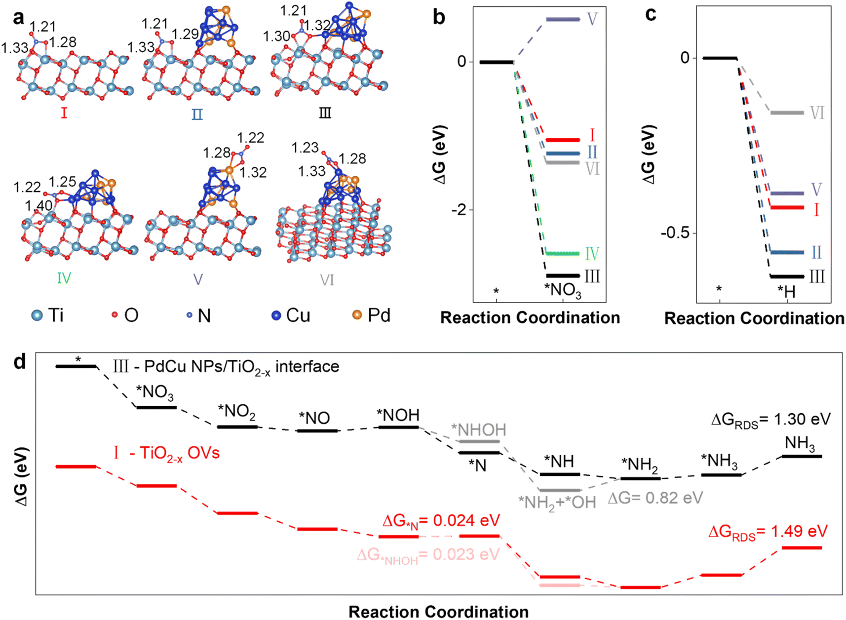 | ||
| Fig. 1 Theoretical prediction of the NITRR using DFT calculations. (a) The structural model and N–O bond length (Å) of *NO3 adsorbed at different sites, (b) the Gibbs free energy (ΔG) of the adsorption of *NO3 at different sites, (c) the Gibbs free energy (ΔG) of the adsorption of *H at different sites, and (d) the ΔG of the entire NITRR process of two possible reaction pathways at the main active sites. | ||
To investigate the effect of PdCu NPs on NO3− adsorbability, we calculated the Gibbs free energy (ΔG) and adsorption energy (Ead) of the adsorbed *NO3 (Fig. 1b and Table S2†). The results show that the introduction of PdCu NPs significantly enhances the adsorbability of NO3−, even though the PdCu NPs are not the main adsorption sites for *NO3. The interface sites between PdCu NPs and TiO2−x (III and IV) exhibit the strongest *NO3 adsorption, where *NO3 is bonded to both Ti3+ and Cu. Specifically, the adsorption configuration (III) is more stable, indicating that Ti3+ at the interface is the primary *NO3 adsorption site. Moreover, we found that the adsorption sites (I, II, and III) related to Ti3+ are the preferred *H adsorption sites over PdCu NPs (V and VI), suggesting that Ti3+ at the interface is the primary *H adsorption site, as shown in Fig. 1c. Therefore, the Ti3+ at the interface is the main active site due to its strongest adsorption of *NO3 and *H. Furthermore, we established a structural model for the two sites (I and III) to investigate the interaction between OVs and PdCu NPs (Fig. S2†). We studied two possible reaction pathways,35,36 for electrocatalytic NH3 synthesis via the NITRR. The structure models of intermediates and reaction pathways are shown in Fig. S3,† and the Ead values of intermediates are provided in Table S3.†
The introduction of PdCu NPs changes the preferred reaction pathway and reduces the reaction barrier in the rate-determining step (RDS). Fig. 1d summarizes the entire NITRR process in two possible reaction pathways at the main active sites of TiO2−x and PdCu NPs/TiO2−x. Prior to the loading of PdCu NPs, path 2 (*NOH → *NHOH → *NH2OH → *NH2) is the preferred reaction pathway due to the lower Gibbs free energy for the formation steps of *NHOH (ΔG = 0.023 eV) and *NH2OH (ΔG = −2.68 eV), compared to the formation steps of *N (ΔG = 0.024 eV) and *NH (ΔG = −2.22 eV), which is consistent with a previous study.36 Following the introduction of PdCu NPs, the hydrogenation reaction of *NOH is significantly enhanced, and the formation of *N becomes more favourable than that of *NHOH. The hydrogenation reactions of *NOH, *N and *NH are spontaneous, but the hydrogenation reaction of the *NH2OH intermediate is significantly suppressed. A similar trend was observed in a previous study, where the formation of *N was significantly promoted and the formation of *NOH and *NH2OH was inhibited during the NITRR over PdCu/Cu2O, in comparison to Cu2O.20 As a result, Path 1 becomes the preferred reaction pathway during the NITRR on PdCu NPs/TiO2−x. Furthermore, the loaded PdCu NPs significantly enhance the *N adsorption (2.28 eV) and accelerate the rate-determining step, from ΔGRDS = 1.49 eV for TiO2−x to ΔGRDS = 1.30 eV for PdCu NPs/TiO2−x (Fig. S4†). Therefore, the introduction of PdCu NPs could enhance the *NO3 and *H adsorption, reduce the energy barrier of the rate-determining step, and promote the electrocatalytic synthesis of NH3via the NITRR.
Based on theoretical predictions, PdCu NPs loaded onto defective TiO2−x with oxygen vacancies are constructed using a facile reduction and solution impregnation method with commercial TiO2. The microscopic morphology of PdCu NPs/TiO2−x (Fig. S5a†) shows that numerous NPs (particle average size is 3.1 ± 0.9 nm) are uniformly distributed on the surface of TiO2−x particles (average size is 34.0 ± 0.8 nm, as shown in Fig. S5b†), The loaded NPs and support exhibit characteristic spacings of 0.199 and 0.234 nm for the (200) lattice planes of the PdCu alloy (JCPDS 48-1551)28 and (112) lattice planes of anatase TiO2 (ICDD 00-004-0477), respectively, indicating that the PdCu alloy NPs are loaded on the surface of TiO2−x (Fig. 2a). The EDS elemental maps (Fig. 2b) reveal that the compositional distributions of both elements (Pd and Cu) in PdCu NPs/TiO2−x are uniform, suggesting an alloy structure. The compositional distributions of Pd, Cu, Ti, and O at the energy dispersive spectroscopy (EDS) mapping surface are presented in Table S4.† The amount of Cu and Pd in PdCu NPs/TiO2−x is quantified via ICP-MS, and the results are shown in Table S5,† which indicates that the chemical formula of the catalyst can be specified as Pd0.026Cu0.051 NPs/TiO2−x. Furthermore, the selected-area electron diffraction (SAED) image of PdCu NPs/TiO2−x (Fig. S6†) reveals the existence of PdCu alloy NPs. The transmission electron microscopy (TEM), high-angle annular dark-field – energy dispersive spectroscopy (HAADF-EDS), and SAED images confirm the successful loading of PdCu NPs and the presence of the PdCu alloy in the PdCu NPs.
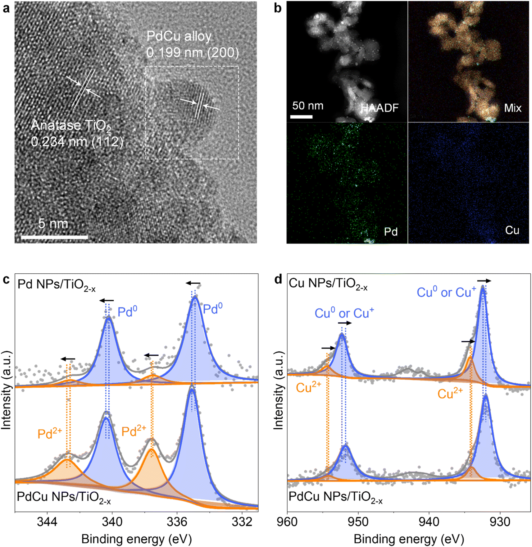 | ||
| Fig. 2 Microscopic morphology of as-prepared PdCu NPs/TiO2−x. (a) TEM image of PdCu NPs on the TiO2−x support, and (b) HAADF-EDS elemental mapping images. XPS spectra of (c) Pd 3d and (d) Cu 2p of Pd, Cu and PdCu NPs supported on TiO2−x. The peak area ratio for Pd2+ increases from 9.8% to 32.3% with the introduction of Cu, while the peak area ratio for Cu2+ decreases from 25.8% to 11.1% with the introduction of Pd. | ||
To further confirm the crystalline phases and oxygen vacancies of the samples, we conducted X-ray diffraction (XRD) and electron paramagnetic resonance (EPR) analyses on the catalysts. As shown in Fig. S7a,† the peaks in TiO2 can be indexed to anatase phase TiO2 (ICDD 00-004-0477). However, the diffraction peak related to Pd or Cu cannot be observed in the PdCu NPs/TiO2−x spectra, indicating that PdCu is highly dispersed on TiO2−x, which also agrees with the results of HAADF-EDS. As shown in Fig. S7b,† the TiO2−x and PdCu NPs/TiO2−x exhibit symmetrical EPR signals at g = 2.003, indicating that the electrons are trapped on oxygen defects.37–39 No oxygen vacancies were found in the TiO2 sample, whereas TiO2−x possesses the highest concentration of oxygen vacancies. The oxygen vacancy concentration decreases after the PdCu NP loading process, indicating that some oxygen vacancies were refilled after PdCu NP loading.40,41
To reveal the chemical states and electron transfer of TiO2−x-based catalysts, we conducted XPS and atomic emission spectroscopy (AES) characterization. As shown in Fig. 2c, the Pd 3d spectra of Pd NPs/TiO2−x exhibit four peaks of Pd0 3d5/2, Pd2+ 3d5/2, Pd0 3d3/2, and Pd2+ 3d3/2.42 The introduction of Cu positively shifts the binding energies (BEs) of Pd 3d, indicating that electrons are transferred from Pd to Cu.43 Furthermore, the peaks of Cu 2p are assigned to Cu0 (or/and Cu+) 2p3/2, Cu2+ 2p3/2, Cu0 (or/and Cu+) 2p1/2, and Cu2+ 2p1/2,44,45 which are negatively shifted with the introduction of Pd, confirming the electron transfer from Pd to Cu, as shown in Fig. 2d. Moreover, it is apparent from Fig. 2c and d that the peak area ratio for Pd2+ increases with the introduction of Cu and the peak area ratio for Cu2+ decreases with the addition of Pd, indicating electron transfer from Pd to Cu and the presence of the PdCu alloy. The Cu0 and Cu+ were distinguished using AES, as shown in Fig. S8.† The peaks of Cu NPs/TiO2−x are assigned to Cu0, Cu+ and Cu2+.46 The main component of Cu in the PdCu NPs is Cu0. For PdCu NPs/TiO2−x, the kinetic energy of the Cu LMM Auger electrons positively shifted, reflecting the transformation from Cu2+ into Cu0 with the introduction of Pd. This indicates that electron transfer from Pd to Cu improves the stability of Cu0.26 As one of the NITRR active elements, the stabilization of Cu0 leads to the promotion of the NITRR.
To understand the interaction between metal NPs and the TiO2−x support, XPS was conducted for Ti 2p and O 1s of the catalysts, as shown in Fig. S9.† With the loading of Pd and Cu NPs, the characteristic Ti 2p and lattice O 1s peaks shift toward higher BEs, indicating electron transfer from the TiO2−x support to Pd and Cu NPs due to the strong metal-support interaction (SMSI).47,48 Presumably, the high concentration of Ti3+ ions in the support transfers electrons to Pd2+ and Cu2+ ions and maintains more Pd and Cu species with low oxidation states. In contrast, the Ti 2p and lattice O 1s peaks shift towards lower BEs with the loading of PdCu NPs, indicating that the PdCu NPs transfer electrons to the TiO2−x support and possess different properties than Pd and Cu NPs, confirming the presence of an alloy state for PdCu NPs. The bimetal synergistic effect of the PdCu alloy promotes the breaking of the N–O bond,49 and the effective d–d coupling of Cu 3d and Pd 4d improves the d-electronic exchange and transfer ability, hence improving the electrocatalytic activity.28 As shown in Fig. S9b,† the peaks of O 1s centred between 530.7 and 531.4 eV are assigned to the O atom correlated with OVs,50 and the negative shifting of the peaks indicates the electron transfer from metal NPs to OVs. It is apparent from the degree of shift that the formation of the PdCu alloy inhibits the electron transfer from Cu to OVs. Furthermore, the peak area ratios for O vacancies are 19.5%, 17.2%, 29.0%, and 22.6% in TiO2−x, Pd NPs/TiO2−x, Cu NPs/TiO2−x, and PdCu NPs/TiO2−x, respectively. The results indicate that introduction of Cu NPs led to an increase in the number of OVs in the TiO2−x support,51 while the presence of Pd inhibited the process. The EPR and XPS analyses confirm the presence of OVs and the PdCu alloy in PdCu NPs/TiO2−x and the enhanced localized electron density at OVs induced by PdCu NPs.
3.2 Electrocatalytic performance
The experiments on NH3 yield were conducted to confirm that the loading of PdCu NPs improves the yield and selectivity of NH3. The linear sweep voltammetry (LSV) curves (Fig. S10†) show that the current density of PdCu NPs/TiO2−x is higher than that of TiO2−x under the same conditions, indicating that the loading of PdCu NPs improves the electron transfer ability on the surface of the catalysts.28 Moreover, the current density in the electrolyte with nitrate is higher than that in the electrolyte without nitrate at a potential higher than −1.0 V. Therefore, the NITRR was studied at different potentials from −1.0 to −1.8 V, as shown in Fig. 3a. PdCu NPs/TiO2−x exhibits a higher NH3 yield rate and faradaic efficiency compared to PdCu NPs and TiO2−x, indicating improved catalytic performance with the loading of PdCu NPs. A higher NH3 yield was achieved at higher potential, but the gradually intensified HER led to a decrease in FE. To verify the inflection point of FE at −1.4 V, the NITRR of PdCu NPs/TiO2−x was studied at lower potentials from −0.1 to −0.6 V (Fig. S11†); it shows that the NH3 yield rate and FE increase with the increase of potential. For PdCu NPs/TiO2−x, the highest FE (38.5%) was achieved at −1.4 V and the NH3 yield was 322.7 μmol cm−2 h−1 under these conditions (compared to 22.6% EF and 112.0 μmol cm−2 h−1 NH3 yield for TiO2−x).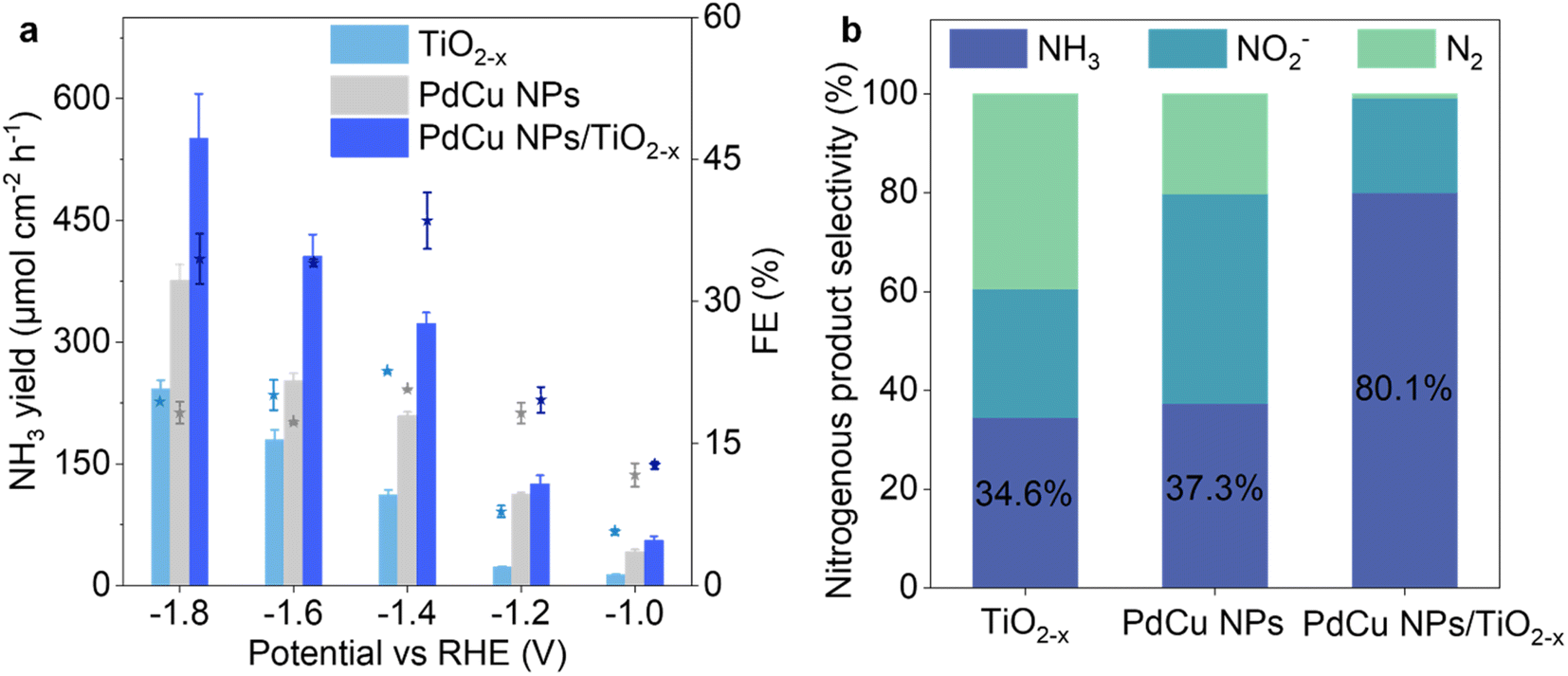 | ||
| Fig. 3 (a) The NH3 yield rate and faradaic efficiency over TiO2−x, PdCu NPs and PdCu NPs/TiO2−x at given potentials. (b) The nitrogenous product selectivity of TiO2−x, PdCu NPs and PdCu NPs/TiO2−x at −1.4 V. | ||
More importantly, the loading of PdCu NPs significantly inhibited the production of N2 (Fig. S12†), and hence the selectivity of NH3 in mainly nitrogenous products (NH3, NO2− and N2) was increased from 34.6% to 80.1% at −1.4 V, as shown in Fig. 3b. The formation of N2 during the NITRR was significantly inhibited after PdCu NP loading, which is consistent with the DFT result (Fig. S14†). While the formation and desorption of *N2 are spontaneous processes on TiO2−x, the energy barrier inhibits these processes after PdCu NP loading (ΔGRDS = 1.07 eV for interface sites of PdCu NPs/TiO2−x). The current densities of PdCu NPs/TiO2−x remained relatively stable during the 48 h NITRR process, and the NH3 yield was relatively stable during 10 cycle tests, as presented in Fig. S15,† confirming the good stability of the catalyst.
We carried out experiments using different types of catalysts, including commercial TiO2, defective TiO2−x, Pd NPs/TiO2−x, Cu NPs/TiO2−x and PdCu NPs/TiO2−x. We found that the loading of PdCu NPs significantly promotes NH3 synthesis, as depicted in Fig. S16.† The results clearly show that PdCu NPs/TiO2−x exhibits the highest NH3 yield rate and current density among the catalysts. The improvement in NH3 yield is more significant at relatively low potential, especially at −1.4 V. This finding indicates that the coexistence of Pd, Cu and partial PdCu alloy in the NPs promotes the synthesis of NH3via the NITRR.20 Pd NPs/TiO2−x and Cu NPs/TiO2−x present similar NH3 yields at low potential (from −1.0 to −1.4 V). In contrast, Cu NPs/TiO2−x significantly improves NH3 yield at higher potential. This suggests that the competitive HER is more significant over Pd compared with Cu species, hence inhibiting the NITRR at high potential.52 The yield rate of NH3 and NO2− was determined to examine the catalytic performance in detail, as shown in Fig. S17 and 18.† The results show that the main liquid product over carbon paper (CP) and PdCu NP loaded CP is NO2−, while the main product over TiO2−x and PdCu NPs/TiO2−x loaded CP is NH3, indicating that the loading of PdCu NPs/TiO2−x promotes the hydrogenation processes from *NO2 to NH3. The promotion effect over PdCu NPs/TiO2−x is more significant than that over TiO2−x. The comparison of NITRR performance between TiO2−x, PdCu NPs and PdCu NPs/TiO2−x confirms that PdCu NP loading on the defective TiO2 support promotes the hydrogenation processes and accelerates nitrate electroreduction to ammonia.
To further reveal the enhancement mechanism of electrocatalytic activity via PdCu NP loading, operando electrochemical impedance spectroscopy (EIS), cyclic voltammetry (CV) measurements, and open circuit potential (OCP) tests were performed. As shown in Fig. 4a, a characteristic peak centred at 3.2 Hz (start at −1.2 V) is attributed to charge storage via adsorption/desorption of *H intermediates.53,54 The peak shifts to higher frequencies (3.2–39.8 Hz) and lower phase degrees (10.5–4.9°) with the increase in potentials (from −1.2 to −1.5 V), indicating enhanced intermediate adsorption and accelerated charge transfer at higher potential.55 In contrast, the Bode plots for TiO2−x in electrolyte with 0.1 M NaNO3 (Fig. 4b) show an extra peak at 1.3 Hz from −0.8 V, which is attributed to the adsorption of *NO3 intermediates. PdCu NPs enhance *H adsorption as evidenced by the characteristic peak of *H adsorption appearing at a lower potential (−0.7 V) compared to that for TiO2−x (−1.2 V), as shown in Fig. 4c. Similarly, the comparison between Fig. 4b, d and f demonstrates that the promotion of *NO3 adsorption is related to the interaction between PdCu NPs and the TiO2−x support. By comprehensively analyzing the results from Fig. 4, it can be concluded that the adsorption of intermediates (*NO3 and *H) is enhanced via PdCu NP loading on TiO2−x, and the equilibrium potential for *NO3 adsorption on PdCu NPs/TiO2−x is lower than that for *H adsorption, as confirmed by the DFT calculations. ΔG of *NO3 adsorption is −1.23 and −2.89 eV at OV and interface sites, respectively, and that for *H is −0.55 and −0.62 eV (Fig. S21†). This indicates that the major adsorption sites for *H are the interface and OV sites of PdCu NPs/TiO2−x rather than metal NPs. The enhanced adsorption of *NO3 and *H intermediates accelerates the hydrogenation processes hence promoting the NITRR process.
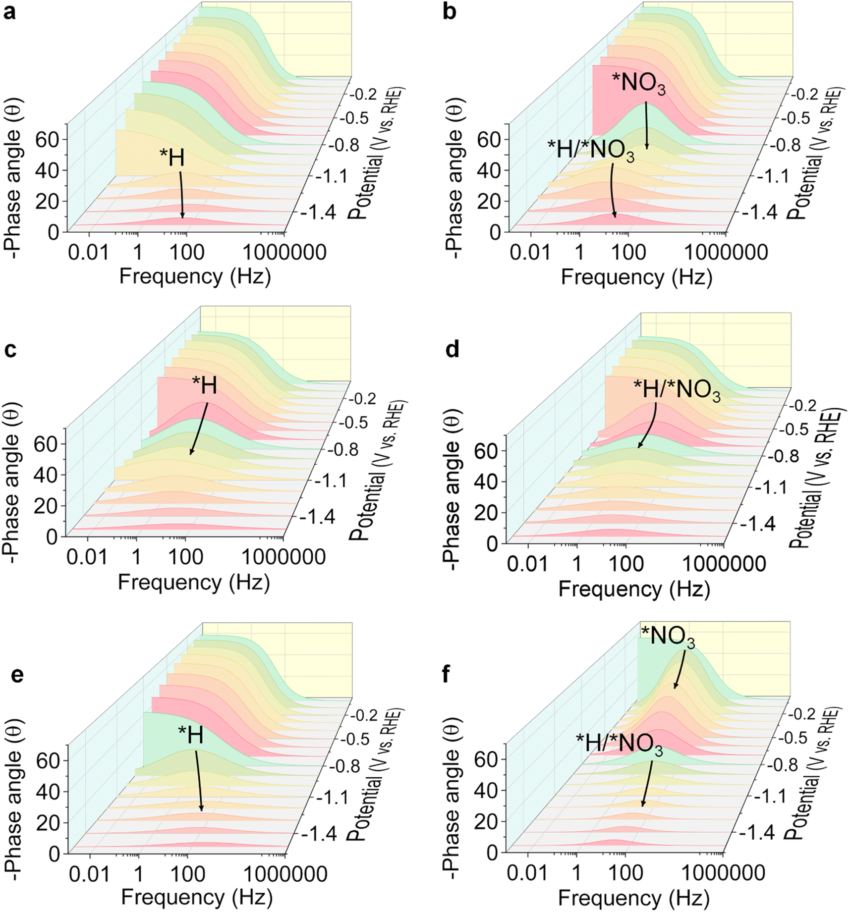 | ||
| Fig. 4 Operando EIS analysis. Bode plots of TiO2−x in 0.5 M Na2SO4 supporting electrolyte (a) without NaNO3 and (b) with 0.1 M NaNO3. Bode plots of PdCu NPs in 0.5 M Na2SO4 supporting electrolyte (c) without NaNO3 and (d) with 0.1 M NaNO3. Bode plots of PdCu NPs/TiO2−x in 0.5 M Na2SO4 supporting electrolyte (e) without NaNO3 and (f) with 0.1 M NaNO3. An equivalent circuit model is shown in Fig. S20.† | ||
The unfitted Nyquist plots at open circuit potential show the intrinsic impedance of TiO2−x, PdCu NPs and PdCu NPs/TiO2−x (Fig. S22a†). This demonstrates that the charge transfer of the catalyst is promoted with the loading of PdCu NPs on TiO2−x, which is consistent with the LSV results. To evaluate the influence of PdCu NPs on the adsorption behaviour of NO3−, the open circuit potential (OCP), which is affected by the variation of absorbates in the Helmholtz layer,56 was analyzed, as shown in Fig. S22b.† With the injection of 0.1 M NaNO3, the electrochemical cell with the PdCu NPs/TiO2−x electrode exhibits a more significant increment in OCP (30.6 mV) than that with the TiO2−x electrode (24.7 mV) and PdCu NP electrode (2.5 mV), indicating that the *NO3 adsorption sites are strongly related to TiO2−x and the *NO3 adsorption is enhanced after PdCu NP loading. Furthermore, the double layer capacitance (Cdl), which was fitted based on the CV result, is considered an indicator of the electrochemically active surface area (ECSA) on different catalysts (Fig. S23†). The Cdl of catalysts decreases from 5.96 to 3.66 mF cm−2 with the loading of PdCu NPs, indicating the agglomeration of TiO2 NPs during the catalyst synthesis process and suggesting that the pore structure of TiO2−x was partially filled by the PdCu NPs. Despite the reduction in ECSA after PdCu NP loading, the PdCu NPs/TiO2−x catalyst shows enhanced catalytic performance. These analyses collectively demonstrate that the enhanced adsorption of *NO3 and *H intermediates and accelerated electron transmission promote the hydrogenation processes, improving ammonia yield and selectivity.
3.3 Mechanism investigation
To dynamically monitor the NITRR process and reveal the NITRR mechanism over PdCu NPs/TiO2−x, in situ electrochemical attenuated total reflectance surface-enhanced infrared absorption spectroscopy (ATR-SEIRAS) was performed (Fig. S24†). A series of vibrational bands can be identified, with peaks centered at 2963, 1648, 1456, 1238, 1180, and 1117 cm−1 attributed to NH4+, H2O, NH4+, –NO3, –NH3, and –NH2, respectively.57–60 The peak intensities for NH4+, –NO3, –NH3 and –NH2 change significantly with an increase in electroreduction time from 0 to 14 min, convincingly confirming that NH3 originates from the NITRR process. However, some peaks from NHx intermediates are covered by –OH. To distinguish Fourier transform infrared spectroscopy (FTIR) peaks from NHx and –OH, comparison experiments based on ATR-SEIRAS characterization using three different electrolytes, including 0.1 M Na15NO3 + 0.5 M Na2SO4, 0.1 M NaNO3 + 0.5 M Na2SO4, and 0.5 M Na2SO4 were conducted. Fig. 5a and b show spectra of 15N isotope labeling experiments. The results clearly show that the center of the –OH peak is located at 3309 cm−1 and the intensity of peaks (3500–3100 and 1800–1500 cm−1) decreases in the electrolyte without NaNO3, which are related to the HER. In contrast, for the electrocatalytic reaction in the electrolyte with 0.1 M NaNO3, the increases in peak intensity are related to the NITRR, with the peaks centered at 3391, 1109 and 1025 cm−1 assigned to –NH2 and the peaks centered at 1652 and 1243 cm−1 assigned to –NO2 and –NO3, respectively.60 Furthermore, the -15NH2 peak center shifts to a lower wavenumber as shown in Fig. 5b which may be related to the isotopic effect or the overlap of adjacent peaks.60 Repeated experiments have consistently shown that the peaks shift to higher wavenumbers, suggesting that the shift is caused by the overlapping of adjacent NH4+ peaks,60 as illustrated in Fig. S25.† Contrast experiments conducted using TiO2−x and PdCu NPs/TiO2−x in ultrapure water and NaNO3 electrolyte indicate that the introduction of PdCu NPs promotes H2O dissociation and *H supply, thereby accelerating hydrogenation and *NH2 formation. The –NH2 peak for TiO2−x moves to a lower wavenumber and lower intensity than that for PdCu NPs/TiO2−x, due to the strong HER (Fig. S26†). However, the spectrum of TiO2−x shows a more intense negative –NO3 peak at 1238 cm−1. Considering that TiO2−x exhibits a much higher N2 yield than PdCu NPs/TiO2−x, the difference in –NO3 behaviour suggests that the N2 formation reaction on PdCu NPs/TiO2−x is inhibited.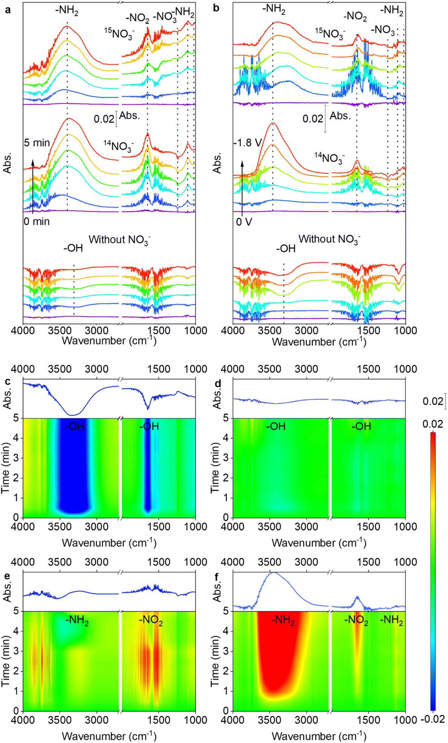 | ||
| Fig. 5 (a) Time-resolved in situ electrochemical ATR-SEIRAS spectra over PdCu NPs/TiO2−x at −1.8 V, and (b) potential-resolved in situ electrochemical ATR-SEIRAS spectra over PdCu NPs/TiO2−x (30 s reaction time at each potential) in 0.5 M Na2SO4 supporting electrolyte with isotopically labelled 0.1 M Na15NO3 electrolytes, unlabeled NaNO3 electrolytes, and electrolytes without NaNO3. The ATR-SEIRAS counter spectrum of (c) TiO2−x in ultrapure water, (d) PdCu NPs/TiO2−x in ultrapure water, (e) TiO2−x in 0.1 M NaNO3, and (f) PdCu NPs/TiO2−x in 0.1 M NaNO3. | ||
The spectra in Fig. 5c–f indicate that PdCu NPs/TiO2−x exhibits a repressed –OH desorption peak in ultrapure water-electrolyte, but an increased formation of the *NH2 intermediate in 0.1 M NaNO3 electrolyte, in comparison to TiO2−x. During the NITRR process, H2O dissociates on the surface of the PdCu NPs/TiO2−x cathode and H+ adsorbs on the surface and participates in the NITRR and HER, while OH− desorbs from the surface and diffuses to the anode, resulting in the observed –OH desorption peak.61 Considering the stronger HER on the PdCu NPs/TiO2−x electrode, the suppressed –OH desorption peak at the same potential indicates stronger H2O dissociation on its surface. The FTIR results are in accordance with the DFT results; as shown in Fig. S27,† the ΔG of the rate-determining step (*H2O + e− = *H + OH−) is reduced from 6.86 to 3.93 eV after PdCu NP loading, which promotes H2O adsorption and dissociation, further leading to accelerated OH− and *H formation, resulting in a suppressed –OH desorption peak and enhanced HER and NITRR. Fig. 5e and f clearly show that the loading of PdCu NPs enhances the formation of NH2 and NO2. The promotion of *NH2 formation is more significant than that of *NO2, suggesting that PdCu NPs have a greater effect on the hydrogenation of *NHx than the reduction of *NO3. These results demonstrate that the PdCu NPs accelerate H2O dissociation, intensify the proton supply, and promote hydrogenation processes, thereby enhancing NH3 formation.
We further performed DFT calculations to gain insights into the reaction mechanism and to reveal the enhanced activity and selectivity of NH3. Fig. 6 depicts the bonding interactions between *NO3 and the catalyst. We calculated the integrated –pCOHP (–ICOHP) to provide quantitative information on bonding strength (by calculating the energy integral up to the Fermi energy).62 Our results indicate that the electron transfer from the catalyst to *NO3 is improved with the introduction of PdCu NPs, and the injected extra electrons fill the Ti–O bonding orbits, as evidenced by the improvement in the -ICOHP of the Ti–O bond from 0.82 to 1.42. The loading of PdCu NPs strengthens the Ti–O bond and weakens the N–O bond, thereby promoting the adsorption and activation of NO3−. Moreover, we observed that the introduction of PdCu NPs increases the d band centre of Ti 3d (Fig. 6e). The d band centre is an indicator of the average energy of d states, and the higher the d states, the more empty the antibonding states, resulting in a stronger adsorption bond, as shown in Fig. 6f.63 The Ti 3d state increases with PdCu loading, indicating electron transfer from PdCu NPs to Ti3+, which enhances the Ti–O bond and promotes NO3− adsorption. This is in line with the findings of the electrochemical experiments and active site study. In addition, PdCu NP loading reduces the selectivity of N2 during the NITRR. Since CNTs@mesoC@CuPd exhibited 98% selectivity for N2 during the NITRR,64 the N2 selectivity is mainly affected by the interaction between Ti3+ and PdCu NPs (Fig. S31 and 32†). The asymmetrical Ti and N pDOS for different electron spin states suggest the presence of unpaired electrons in *N and *N2 before PdCu NP loading. For the *N intermediate, the significantly enhanced bonding strength (from 4.50 to 7.17) after loading PdCu NPs suggests enhanced *N adsorption (consistent with Ead, as shown in Table S3†). The improved Bader charge shows that PdCu loading promotes electron transfer to *N and enhances the local electron density of *N. The enhanced local electron density and facilitated H+ formation and adsorption together promote the hydrogenation process, leading to the promotion of *NH formation and inhibition of *N desorption and *N2 formation. For the *N2 intermediate, the enhanced adsorption of *N2 is evidenced in Fig. S30,† due to the negligible bond strength loss of the N–Ti bond and the formation of an extra N–Cu bond. The NN bond is weakened (reduced from 21.98 to 17.25), and the positive shifting of pDOS indicates the activation of N2. As a result, the desorption of *N2 is inhibited and the formation of *NNH is promoted, consistent with the NRR study.32
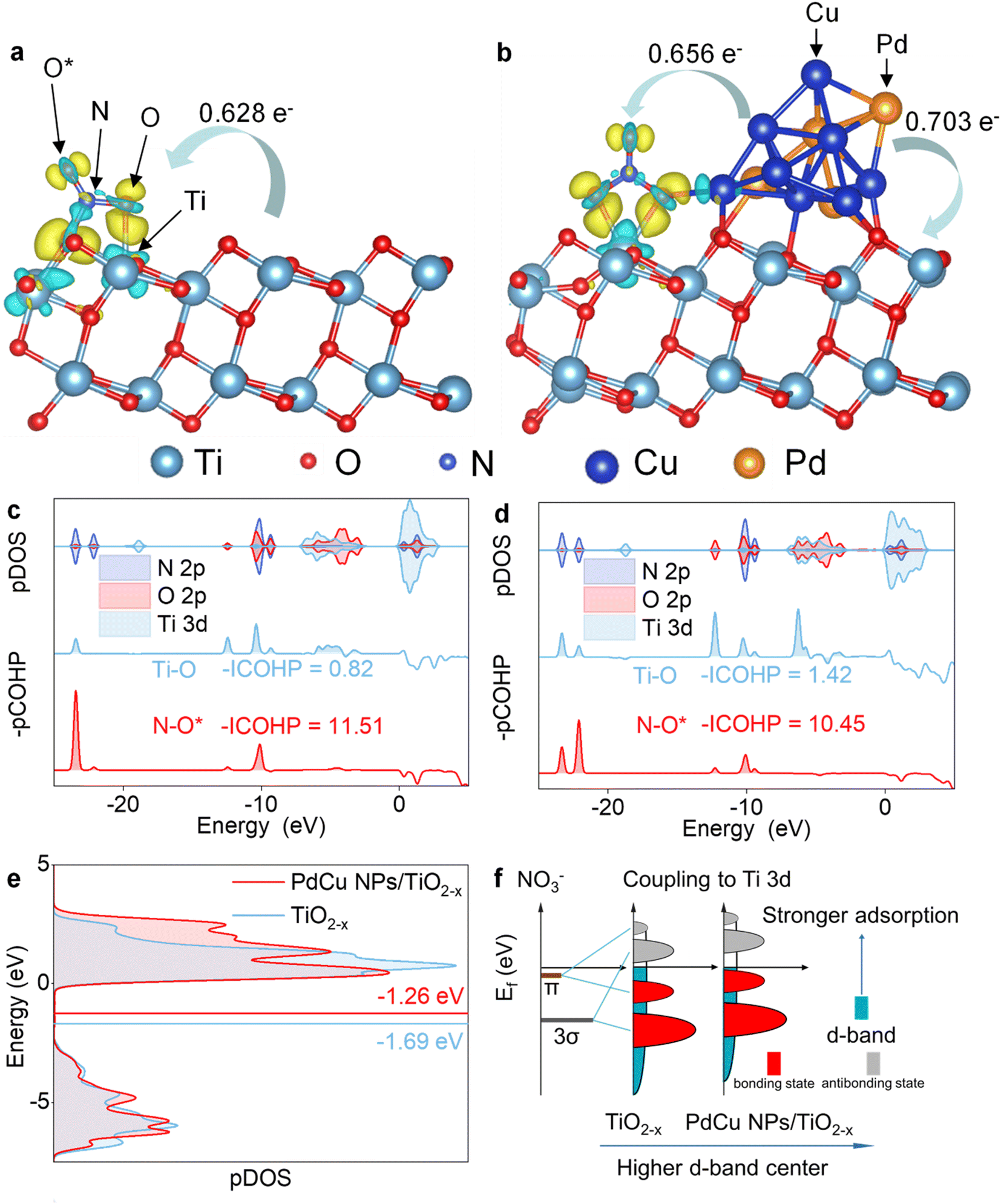 | ||
| Fig. 6 The differential charge density map and electron transfer between PdCu NPs, TiO2−x, and the *NO3 intermediate adsorbed at (a) TiO2−x OVs and (b) PdCu NPs/TiO2−x interface, respectively. The partial density of states (PDOS) and partial crystal orbital Hamilton population (COHP) of the *NO3 intermediate adsorbed at (c) TiO2−x OVs and (d) PdCu NPs/TiO2−x interface. (e) The d band centre of Ti 3d of TiO2−x and PdCu NPs/TiO2−x. (f) The schematic illustration of the higher d-band centre promoting catalytic kinetics. (With an isosurface value of 0.005 electrons per Å3, the green areas represent electron depletion and the yellow areas represent electron accumulation). | ||
The pDOS of other intermediates, including *NO2, *NO, *N, *NH, *NH2 and *NH3 were studied to reveal the effect of PdCu NPs on the hydrogenation process, as shown in Fig. S33 to S38.† For *NO2 intermediates (Fig. S33†), the peaks of N 2p and O 2p orbits are co-located between −9.3 and −7.7 eV. The N 2p peaks in this region can be regarded as an indicator of the N–O bond since the major contributions of N 2p and O 2p are present. The results suggest that the electron density on Ti3+ is increased, and more electrons fill in the N–Ti orbits, enhancing the N–Ti bonding state and weakening the N–O bond due to the introduction of PdCu NPs, consistent with the results for *NO intermediates (Fig. S34†). Therefore, the adsorption and activation of *NOx intermediates are enhanced with PdCu NP loading, as supported by the results from electrochemical characterization and DFT calculations of Ead. In the case of the *N intermediate (Fig. S35†), the N–Ti bond is strengthened and *N is stabilized due to the presence of PdCu NPs. Furthermore, negative shifts (1.35 eV) in the N 2p and Ti 3d peaks indicate that more electrons fill the vacant N 2p and Ti 3d orbits due to the electrons provided by PdCu NPs. Similar negative shifts (0.84 eV) can be found in *NH (Fig. S36†), and the shifts of pDOS reduce with the hydrogenation process, as shown in the pDOS of *NH2 (Fig. S37†), due to the occupation of N 2p orbits during hydrogenation. This finding suggests that the injection of electrons from PdCu NPs promotes the hydrogenation processes. For the *NH3 intermediate (Fig. S38†), the PDOS of Ti 3d and N 2p for TiO2−x and PdCu NPs/TiO2−x are studied to investigate the effect of PdCu NPs on the *NH3 desorption process. After PdCu NP loading, the peak intensity of Ti 3d and N 2p decreases, indicating that the interaction between Ti3+ and *NH3 weakens and the desorption of *NH3 is enhanced. In contrast to the theoretical prediction of the NITRR at transition metal surfaces,65 PdCu NPs promote nitrate electroreduction to ammonia instead of NO, due to the interaction between PdCu NPs and OVs. The comprehensive study of charge density, Bader charge, pDOS and COHP of intermediates reveals that PdCu NPs enhance nitrate electroreduction to ammonia by promoting hydrogenation and inhibiting the formation of N2.
4. Conclusions
In conclusion, we demonstrated enhanced NH3 selectivity and yield in the NITRR via introducing PdCu NPs to modulate the local electrons of OVs on a defective TiO2−x support. Our in situ characterization and DFT calculation results clearly show that electron injection from PdCu NPs effectively regulates the localized electron density of OVs, boosting the hydrogenation processes and inhibiting N–N coupling, ultimately enhancing the NH3 selectivity and yield. This work sheds light on the mechanism behind the enhancement of alloy loading on the activity and selectivity of NH3 synthesis via the NITRR and provides a feasible approach to design alloying catalysts for selective NH3 synthesis via the NITRR.Author contributions
Haoran Wu: investigation, formal analysis, writing the original draft. Heng Guo: conceptualization, review, funding acquisition. Ying Zhou: conceptualization, review, supervision, funding acquisition. Fengying Zhang: methodology, review. Peng Yang: methodology. Jiaxin Liu: methodology. Yuantao Yang: methodology. Zhenfeng Huang: resources. Guidong Yang: resources. Xin Tu: resources, review. Chenyuan Zhu: review. Weitao Wang: review.Conflicts of interest
There are no conflicts to declare.Acknowledgements
This work was supported by the National Key R&D Project of China (Grant No. 2020YFA0710000), the National Natural Science Foundation of China (22109132), the Provincial Key Research and Development Project of Sichuan (22SYSX0142), the International Science and Technology Cooperation Project of Chengdu (2021-GH02-00052-HZ), the Technology Innovation R&D Project of Chengdu (2022-YF05-00978-SN) and the Scientific Research Starting Project of SWPU (No.2021QHZ014 and 2021QHZ028). X. T. acknowledges the support of the Engineering and Physical Sciences Research Council (EP/X002713/1).References
- S. L. Foster, S. I. P. Bakovic, R. D. Duda, S. Maheshwari, R. D. Milton, S. D. Minteer, M. J. Janik, J. N. Renner and L. F. Greenlee, Nat. Catal., 2018, 1, 490–500 CrossRef.
- C. Tang and S. Z. Qiao, Chem. Soc. Rev., 2019, 48, 3166–3180 RSC.
- Y. Ren, C. Yu, X. Tan, H. Huang, Q. Wei and J. Qiu, Energy Environ. Sci., 2021, 14, 1176–1193 RSC.
- D. R. MacFarlane, J. Choi, B. H. R. Suryanto, R. Jalili, M. Chatti, L. M. Azofra and A. N. Simonov, Adv. Mater., 2020, 32, 1904804 CrossRef CAS PubMed.
- L. Li, C. Tang, B. Xia, H. Jin, Y. Zheng and S. Z. Qiao, ACS Catal., 2019, 9, 2902–2908 CrossRef CAS.
- P. H. van Langevelde, I. Katsounaros and M. T. M. Koper, Joule, 2021, 5, 290–294 CrossRef.
- L. Li, C. Tang, X. Cui, Y. Zheng, X. Wang, H. Xu, S. Zhang, T. Shao, K. Davey and S. Qiao, Angew. Chem., Int. Ed., 2021, 60, 14131–14137 CrossRef CAS PubMed.
- X. Zhang, T. Wu, H. Wang, R. Zhao, H. Chen, T. Wang, P. Wei, Y. Luo, Y. Zhang and X. Sun, ACS Catal., 2019, 9, 4609–4615 CrossRef CAS.
- L. Yang, S. Feng and W. Zhu, J. Phys. Chem. Lett., 2022, 13, 1726–1733 CrossRef CAS PubMed.
- T. Mou, Y. Wang, P. Deák, H. Li, J. Long, X. Fu, B. Zhang, T. Frauenheim and J. Xiao, J. Phys. Chem. Lett., 2022, 13, 9919–9927 CrossRef CAS PubMed.
- P. Yang, H. Guo, H. Wu, F. Zhang, J. Liu, M. Li, Y. Yang, Y. Cao, G. Yang and Y. Zhou, J. Colloid Interface Sci., 2023, 636, 184–193 CrossRef CAS PubMed.
- H. Guo, M. Li, Y. Yang, R. Luo, W. Liu, F. Zhang, C. Tang, G. Yang and Y. Zhou, Small, 2023, 19, 2207743 CrossRef CAS PubMed.
- S. B. Patil and D. Y. Wang, Small, 2020, 16, 2002885 CrossRef CAS PubMed.
- S. B. Patil, H. Chou, Y. Chen, S. Hsieh, C. Chen, C. Chang, S. Li, Y. Lee, Y. Lin, H. Li, Y. J. Chang, Y. Lai and D. Wang, J. Mater. Chem. A, 2021, 9, 1230–1239 RSC.
- S. B. Patil, T. Liu, H. Chou, Y. Huang, C. Chang, Y. Chen, Y. Lin, H. Li, Y. Lee, Y. J. Chang, Y. Lai, C. Wen and D. Wang, J. Phys. Chem. Lett., 2021, 12, 8121–8128 CrossRef CAS PubMed.
- T. Hu, M. Wang, C. Guo and C. M. Li, J. Mater. Chem. A, 2022, 10, 8923–8931 RSC.
- J. M. McEnaney, S. J. Blair, A. C. Nielander, J. A. Schwalbe, D. M. Koshy, M. Cargnello and T. F. Jaramillo, ACS Sustain. Chem. Eng., 2020, 8, 2672–2681 CrossRef CAS.
- Q. Li, Y. Liu, Z. Wan, H. Cao, S. Zhang, Y. Zhou, X. Ye, X. Liu and D. Zhang, Chin. Chem. Lett., 2022, 33, 3835–3841 CrossRef CAS.
- F. Ni, Y. Ma, J. Chen, W. Luo and J. Yang, Chin. Chem. Lett., 2021, 32, 2073–2078 CrossRef CAS.
- H. Yin, Z. Chen, S. Xiong, J. Chen, C. Wang, R. Wang, Y. Kuwahara, J. Luo, H. Yamashita, Y. Peng and J. Li, Chem Catal., 2021, 1, 1088–1103 CrossRef CAS.
- Z. Zhang, Y. Xu, W. Shi, W. Wang, R. Zhang, X. Bao, B. Zhang, L. Li and F. Cui, Chem. Eng. J., 2016, 290, 201–208 CrossRef CAS.
- Z. Y. Wu, M. Karamad, X. Yong, Q. Huang, D. A. Cullen, P. Zhu, C. Xia, Q. Xiao, M. Shakouri, F. Y. Chen, J. Y. T. Kim, Y. Xia, K. Heck, Y. Hu, M. S. Wong, Q. Li, I. Gates, S. Siahrostami and H. Wang, Nat. Commun., 2021, 12, 2870 CrossRef CAS PubMed.
- G. F. Chen, Y. Yuan, H. Jiang, S. Y. Ren, L. X. Ding, L. Ma, T. Wu, J. Lu and H. Wang, Nat. Energy, 2020, 5, 605–613 CrossRef CAS.
- R. Jia, Y. Wang, C. Wang, Y. Ling, Y. Yu and B. Zhang, ACS Catal., 2020, 10, 3533–3540 CrossRef CAS.
- X. Wan, W. Guo, X. Dong, H. Wu, X. Sun, M. Chu, S. Han, J. Zhai, W. Xia, S. Jia, M. He and B. Han, Green Chem., 2022, 24, 1090–1095 RSC.
- M.-M. Shi, D. Bao, S.-J. Li, B.-R. Wulan, J.-M. Yan and Q. Jiang, Adv. Energy Mater., 2018, 8, 1800124 CrossRef.
- X. Zhang, Y. Cao, Z. F. Huang, S. Zhang, C. Liu, L. Pan, C. Shi, X. Zhang, Y. Zhou, G. Yang and J. J. Zou, Carbon Energy, 2023, 5, e266 CrossRef CAS.
- W. Tong, B. Huang, P. Wang, L. Li, Q. Shao and X. Huang, Angew Chem. Int. Ed. Engl., 2020, 59, 2649–2653 CrossRef CAS PubMed.
- F. Pang, Z. Wang, K. Zhang, J. He, W. Zhang, C. Guo and Y. Ding, Nano Energy, 2019, 58, 834–841 CrossRef CAS.
- Z. Wang, X. Wu, J. Liu, D. Zhang, H. Zhao, X. Zhang, Y. Qin, N. Nie, D. Wang, J. Lai and L. Wang, Nano Lett., 2021, 21, 9580–9586 CrossRef CAS PubMed.
- L. Han, Z. Ren, P. Ou, H. Cheng, N. Rui, L. Lin, X. Liu, L. Zhuo, J. Song, J. Sun, J. Luo and H. L. Xin, Angew. Chem., 2021, 133, 349–354 CrossRef.
- C. Liu, X. Guo, Z.-F. Huang, J. Li, L. Gan, L. Pan, C. Shi, X. Zhang, G. Yang and J.-J. Zou, Mater. Chem. Front., 2022, 6, 2190–2200 RSC.
- C. Chen, X. Zhu, X. Wen, Y. Zhou, L. Zhou, H. Li, L. Tao, Q. Li, S. Du, T. Liu, D. Yan, C. Xie, Y. Zou, Y. Wang, R. Chen, J. Huo, Y. Li, J. Cheng, H. Su, X. Zhao, W. Cheng, Q. Liu, H. Lin, J. Luo, J. Chen, M. Dong, K. Cheng, C. Li and S. Wang, Nat. Chem., 2020, 12, 717–724 CrossRef CAS PubMed.
- W. Gao, N. Guan, J. Chen, X. Guan, R. Jin, H. Zeng, Z. Liu and F. Zhang, Appl. Catal., B, 2003, 46, 341–351 CrossRef CAS.
- J. Li, R. Chen, J. Wang, Y. Zhou, G. Yang and F. Dong, Nat. Commun., 2022, 13, 1098 CrossRef CAS PubMed.
- Z. Wei, X. Niu, H. Yin, S. Yu and J. Li, Appl. Catal., A, 2022, 636, 118596 CrossRef CAS.
- Q. Ren, Y. He, H. Wang, Y. Sun and F. Dong, ACS Catal., 2022, 12, 14015–14025 CrossRef CAS.
- N. Zhang, X. Li, H. Ye, S. Chen, H. Ju, D. Liu, Y. Lin, W. Ye, C. Wang, Q. Xu, J. Zhu, L. Song, J. Jiang and Y. Xiong, J. Am. Chem. Soc., 2016, 138, 8928–8935 CrossRef CAS PubMed.
- S. Chen, H. Wang, Z. Kang, S. Jin, X. Zhang, X. Zheng, Z. Qi, J. Zhu, B. Pan and Y. Xie, Nat. Commun., 2019, 10, 788 CrossRef CAS PubMed.
- K. Ye, K. Li, Y. Lu, Z. Guo, N. Ni, H. Liu, Y. Huang, H. Ji and P. Wang, TrAC, Trends Anal. Chem., 2019, 116, 102–108 CrossRef CAS.
- X. Ma, Y. Dai, L. Yu and B. Huang, Sci. Rep., 2014, 4, 3986 CrossRef PubMed.
- K. Jiang, P. Wang, S. Guo, X. Zhang, X. Shen, G. Lu, D. Su and X. Huang, Angew. Chem., Int. Ed., 2016, 55, 9030–9035 CrossRef CAS PubMed.
- Z. Guo, X. Kang, X. Zheng, J. Huang and S. Chen, J. Catal., 2019, 374, 101–109 CrossRef CAS.
- J. Huang, T. Ding, K. Ma, J. Cai, Z. Sun, Y. Tian, Z. Jiang, J. Zhang, L. Zheng and X. Li, ChemCatChem, 2018, 10, 3862–3871 CrossRef CAS.
- Z. Jin, C. Liu, K. Qi and X. Cui, Sci. Rep., 2017, 7, 39695 CrossRef CAS PubMed.
- X. Yuan, S. Chen, D. Cheng, L. Li, W. Zhu, D. Zhong, Z. J. Zhao, J. Li, T. Wang and J. Gong, Angew. Chem., Int. Ed., 2021, 60, 15344–15347 CrossRef CAS PubMed.
- J. Sá, J. Bernardi and J. A. Anderson, Catal. Letters, 2007, 114, 91–95 CrossRef.
- C. Zhang, L. Wang, U. J. Etim, Y. Song, O. M. Gazit and Z. Zhong, J. Catal., 2022, 413, 284–296 CrossRef CAS.
- J. Sun, H. Yang, W. Gao, T. Cao and G. Zhao, Angew. Chem., Int. Ed., 2022, 61, e202211373 CrossRef CAS PubMed.
- B. Bharti, S. Kumar, H. N. Lee and R. Kumar, Sci. Rep., 2016, 6, 32355 CrossRef CAS PubMed.
- W. P. Utomo, H. Wu and Y. H. Ng, Small, 2022, 18, 2200996 CrossRef CAS PubMed.
- M. Nunes, D. M. Fernandes, M. V. Morales, I. Rodríguez-Ramos, A. Guerrero-Ruiz and C. Freire, Catal. Today, 2020, 357, 279–290 CrossRef CAS.
- V. Augustyn, P. Simon and B. Dunn, Energy Environ. Sci., 2014, 7, 1597 RSC.
- R. Ge, Y. Wang, Z. Li, M. Xu, S. Xu, H. Zhou, K. Ji, F. Chen, J. Zhou and H. Duan, Angew Chem. Int. Ed. Engl., 2022, 61, e202200211 CrossRef CAS PubMed.
- D. A. Aikens, J. Chem. Educ., 1983, 60, A25 CrossRef.
- Y. Lu, T. Liu, C. L. Dong, Y. C. Huang, Y. Li, J. Chen, Y. Zou and S. Wang, Adv. Mater., 2021, 33, 2007056 CrossRef CAS PubMed.
- P. Li, Z. Zhou, Q. Wang, M. Guo, S. Chen, J. Low, R. Long, W. Liu, P. Ding, Y. Wu and Y. Xiong, J. Am. Chem. Soc., 2020, 142, 12430–12439 CrossRef CAS PubMed.
- F. Lai, N. Chen, X. Ye, G. He, W. Zong, K. B. Holt, B. Pan, I. P. Parkin, T. Liu and R. Chen, Adv. Funct. Mater., 2020, 30, 1907376 CrossRef CAS.
- Y. Yao, S. Zhu, H. Wang, H. Li and M. Shao, Angew. Chem., Int. Ed., 2020, 59, 10479–10483 CrossRef CAS PubMed.
- M. Y. Mihaylov, V. R. Zdravkova, E. Z. Ivanova, H. A. Aleksandrov, P. S. Petkov, G. N. Vayssilov and K. I. Hadjiivanov, J. Catal., 2021, 394, 245–258 CrossRef CAS.
- A. Li, S. Kong, C. Guo, H. Ooka, K. Adachi, D. Hashizume, Q. Jiang, H. Han, J. Xiao and R. Nakamura, Nat. Catal., 2022, 5, 109–118 CrossRef CAS.
- S. Steinberg and R. Dronskowski, Crystals, 2018, 8, 225 CrossRef.
- J. K. Nørskov, F. Abild-Pedersen, F. Studt and T. Bligaard, Proc. Natl. Acad. Sci., 2011, 108, 937–943 CrossRef PubMed.
- H. Xu, J. Chen, Z. Zhang, C.-T. Hung, J. Yang and W. Li, Adv. Mater., 2023, 35, 2207522 CrossRef CAS PubMed.
- J.-X. Liu, D. Richards, N. Singh and B. R. Goldsmith, ACS Catal., 2019, 9, 7052–7064 CrossRef CAS.
Footnote |
| † Electronic supplementary information (ESI) available. See DOI: https://doi.org/10.1039/d3ta04155g |
| This journal is © The Royal Society of Chemistry 2023 |