
 Open Access Article
 This Open Access Article is licensed under a Creative Commons Attribution-Non Commercial 3.0 Unported Licence
Continuous wet chemical synthesis of Mo(C,N,O)x as anode materials for Li-ion batteries†
Mana
Abdirahman Mohamed‡
 a,
Stefanie
Arnold‡
bc,
Oliver
Janka
a,
Antje
Quade
e,
Jörg
Schmauch
f,
Volker
Presser
*bcd and
Guido
Kickelbick
*a
a,
Stefanie
Arnold‡
bc,
Oliver
Janka
a,
Antje
Quade
e,
Jörg
Schmauch
f,
Volker
Presser
*bcd and
Guido
Kickelbick
*a
aSaarland University, Inorganic Solid-State Chemistry, Campus C4 1, 66123 Saarbrücken, Germany. E-mail: guido.kickelbick@uni-saarland.de
bINM – Leibniz Institute for New Materials, 66123 Saarbrücken, Germany. E-mail: volker.presser@leibniz-inm.de
cSaarland University, Department of Materials Science and Engineering, 66123 Saarbrücken, Germany
dSaarene – Saarland Center for Energy Materials and Sustainability, 66123 Saarbrücken, Germany
eLeibniz Institute for Plasma Science and Technology, Felix-Hausdorff-Straße 2, 17489 Greifswald, Germany
fPhysics Department, Saarland University, Campus D2.2, 66123 Saarbrücken, Germany
First published on 7th August 2023
Abstract
Molybdenum carbides, oxides, and mixed anionic carbide–nitride–oxides Mo(C,N,O)x are potential anode materials for lithium-ion batteries. Here we present the preparation of hybrid inorganic–organic precursors by a precipitation reaction of ammonium heptamolybdate ((NH4)6Mo7O24) with para-phenylenediamine in a continuous wet chemical process known as a microjet reactor. The mixing ratio of the two components has a crucial influence on the chemical composition of the obtained material. Pyrolysis of the precipitated precursor compounds preserved the size and morphology of the micro- to nanometer-sized starting materials. Changes in pyrolysis conditions such as temperature and time resulted in variations of the final compositions of the products, which consisted of mixtures of Mo(C,N,O)x, MoO2, Mo2C, Mo2N, and Mo. We optimized the reaction conditions to obtain carbide-rich phases. When evaluated as an anode material for application in lithium-ion battery half-cells, one of the optimized materials shows a remarkably high capacity of 933 mA h g−1 after 500 cycles. The maximum capacity is reached after an activation process caused by various conversion reactions with lithium.
1. Introduction
Due to their high energy density, long cycle life, and high working potential, rechargeable lithium-ion batteries (LIBs) dominate the current electrochemical energy storage market.1–3 The ever-growing demand for LIBs, especially in electric vehicles, has increased the necessity for new electrode materials with improved battery performance. Graphite remains one of the most important anode materials for LIBs, with a theoretical capacity of 372 mA h g−1.4,5 Designing new anode materials with high specific capacity is becoming an increasingly important requirement for high-performance LIBs. Therefore, research is focussing on other materials with enhanced capacity. Particularly attractive are alloying or conversion-type materials.6–9 For example, molybdenum oxides provide a theoretical capacity of 1117 mA h g−1 for MoO3![[thin space (1/6-em)]](https://www.rsc.org/images/entities/char_2009.gif) 10–12 and 838 mA h g−1 for MoO213–15 when forming Li-rich phases during conversion reaction. Molybdenum carbides with the compositions Mo2C or MoCx show favorable lithium storage properties compared to pure oxides due to better electrical conductivity and excellent mechanical and chemical stability.16 Combining the properties of molybdenum oxides and carbides could lead to promising electrode materials for LIBs.
10–12 and 838 mA h g−1 for MoO213–15 when forming Li-rich phases during conversion reaction. Molybdenum carbides with the compositions Mo2C or MoCx show favorable lithium storage properties compared to pure oxides due to better electrical conductivity and excellent mechanical and chemical stability.16 Combining the properties of molybdenum oxides and carbides could lead to promising electrode materials for LIBs.
A promising way to produce molybdenum carbides and molybdenum oxycarbides is through precursor methods. The milder reaction conditions, in combination with a versatile composition of the precursors, allow better tailoring of the size and morphology of the final product and are less energy consuming than other methods.17 Suitable precursors can be obtained from precipitation reactions, which are subsequently pyrolyzed to the target compounds. Typical examples for this route are mixtures of various molybdates with aniline,18para-phenylenediamine,19 2-methylimidazole,16 melamine,20 or dicyandiamide.21 Giordano et al. also showed that Mo2C and Mo2N nanoparticles could be prepared from MoCl5 and urea.22 A facile preparation method via self-polymerization of dopamine for Mo2C nanoparticles supported on 3D carbon micro flowers was discovered by Huang et al.23 Li et al. developed a new pathway for mesoporous and nanosized Mo2C/Mo2N heterojunctions using dopamine-molybdate coordination precursor with silica nanoparticles,24 while mixed salt precursors consisting of a molybdenum hexamethylenetetramine complex were presented by Wang et al.25
A popular source for molybdenum in the precursors is ammonium heptamolybdate (NH4)6Mo7O24 (AHM), which can form inorganic–organic hybrid precipitates with various organic molecules that can be pyrolyzed to Mo2C.22,26 The pyrolysis conditions for converting the precursors to the carbides must be accurately controlled because of the many binary compounds in the Mo–O and Mo–C systems. Examples include orthorhombic high-temperature Mo4O11,27,28 monoclinic MoO2,28 orthorhombic Mo2C29 (ESI, Fig. S1a†), and even cubic Mo.30,31 At around 600 °C, MoO2, MoC, and C are in equilibrium. Molybdenum oxycarbide can be obtained at this temperature, while above 650 °C Mo2C is the most stable phase.32 Other molybdenum carbide products, such as cubic (ESI, Fig. S1b†) or hexagonal (ESI, Fig. S1c†) MoCx (x = 0.46–0.75) can also be formed. The use of amine ligands may furthermore lead to the formation of nitrides such as Mo2N.22,32
The present work uses the continuous26,33,34 and easy-to-scale35–37 microjet reactor synthesis to obtain nanostructured Mo-based particles. The continuous wet chemical process allows for larger production volumes while often also a better control over reaction conditions, and thus a better control over particle morphology and reproducibility are achieved. We present a systematic study on the precursor formation by the microjet method and subsequent pyrolysis of Mo(C,N,O)x materials. In a previous publication, we could show that different precursor compositions are obtained depending on the ratio between the molybdenum source and the para-phenylenediamin (PPD) in the reactor.26 The resulting non-pyrolyzed materials showed different electrochemical behavior in battery applications depending on their composition. The precursors are obtained as precipitates in the microjet reaction by an exchange reaction of the ammonium ions in AHM against the protonated PPD. In our present study, we will focus on the pyrolysis of the achieved precursors and their electrochemical behavior. The influence of various parameters, such as the decomposition temperature, which affects the molybdenum carbide species, and the effect of the precursor composition was analyzed to understand the role of the carbon source during the pyrolysis. In addition, we carried out an electrochemical characterization on the obtained compounds to understand the effect of composition on electrochemical parameters.
2. Experimental section
2.1. Materials
Ammonium heptamolybdate tetrahydrate ((NH4)6Mo7O24·4H2O, AHM; ≥99%) was purchased from Carl Roth. para-Phenylenediamine (PPD; 97%) was ordered from Alfa Aesar. Hydrochloric acid (HCl; 37%) was bought from Bernd Kraft GmbH. Ethanol (99% denatured with 1% petroleum ether) was received from BCD Chemie GmbH. Conductive carbon additive (Type C65) was ordered from IMERYS Graphite&Carbon. Polyvinylidene fluoride (PVdF, 99.5%), dimethyl sulfoxide (DMSO, anhydrous, ≥99.9%), and lithium hexafluorophosphate (LiPF6; LP 30; 1 M in an ethylene carbonate (EC) and dimethyl carbonate (DMC) mixture in the ratio EC:DMC (1:1 by volume)) as electrolyte were obtained from Sigma-Aldrich. No further purification was conducted for all chemicals.
2.2. Material synthesis
The PPD/molybdate precursor synthesis is described in detail in our previous work.26 Briefly, AHM and PPD were dissolved in water, and a 0.25–0.10 M diluted HCl solution was prepared. These solutions were the educt solution for the beaker and microjet precipitation. For the microjet experiments, two HPLC pumps (LaPrep P110 preparative HPLC pumps (VWR)) were used to deliver the solutions with a flow rate of 250 mL min−1 at room temperature. The reaction occurred in the microjet reactor, where the solutions were pushed at high pressure through a 300 μm diameter nozzle into the reaction chamber. Nitrogen gas was applied to remove the particles formed.26,33 The particles were isolated by centrifugation (8000 rpm, 15 min) at the end of the precipitation. All products were washed with ethanol and dried at 80 °C. Finally, the obtained precursors were pyrolyzed under argon flow with the temperature program shown in Fig. 1. | ||
| Fig. 1 Temperature program for the pyrolysis (RT: room temperature). | ||
2.3. Material characterization
Powder X-ray diffraction (PXRD) measurements were performed using a Bruker D8-A25-Advance diffractometer in a Bragg–Brentano geometry with CuKα-radiation (Cu-Kα, λ = 154.06 pm, 40 kV, 40 mA). PXRD was conducted with a total measurement time of 1 h and from 6–130° 2θ with a step size of 0.013°. The powder is applied to a recessed stainless steel or a silicon zero-background carrier. Rietveld analysis using Topas 5 was applied to quantify the crystalline phases in the samples.38 The crystallographic data for the Rietveld refinements were obtained from Crystallographic Open Database (COD) and the Inorganic Crystal Structure Database (ICSD).Scanning electron microscopy (SEM) was carried out using JEOL JSM-7000 F microscope at a working distance of 10 mm and operating at 20 kV. A small amount was placed on a sample stub covered with carbon adhesive film to prepare the samples, and then a thin gold layer was deposited via sputter coating.
The elemental analyses were performed on an Elementar Vario Micro cube. 1.5–2.5 mg of the substance to be analyzed is weighed out. The sample weight is determined to the nearest 0.001 mg. The powders are weighed into special tin boats, then folded into cube-shaped packets.
X-ray photoelectron spectroscopy (XPS) was conducted using an Axis Supra (Kratos Analytical) spectrometer. Survey and elemental scans were recorded using Al-Kα radiation with a power of 150 W and a pass energy of 160 eV and 80 eV, respectively. Concerning high-resolution measurements, 225 W at 10 eV was employed. The data was processed with CasaXPS (Casa Software, version 2.3.15). The powders were sprinkled onto the surface of a small piece (5 × 5 mm2) of sticky carbon tape using a spatula. The flat side of the spatula was used to press the powders firmly into the tape. After removing the loose powder from the surface of the sample bar, the holder was inserted into the XPS load lock.
A Renishaw inVia Raman microscope was used to collect Raman spectra, equipped with a neodymium-doped yttrium-aluminum-garnet laser with an excitation wavelength of 532 nm and a laser power of approximately 0.05 mW at the sample surface, a 2400 mm per grating, and a 50× objective with a numerical aperture of 0.75. From each sample, five different spots were collected with five accumulations and 30 s acquisition time. Normalization of all spectra from 0–1 was performed. The powder samples were fixed onto the glass microscope slides. The spectra underwent automatic cosmic ray removal. Before and after the measurement, a silicon standard was used to calibrate the system.
Transmission electron microscopy (TEM) was performed using a JEOL JEM-2011 and a JEOL JEM-ARM 200 instrument. Previously, the sample was suspended in ethanol, assisted by ultrasonic treatment, then that suspension was deposited on carbon-coated copper grids (Plano S160-3).
3. Electrochemical characterization
3.1. Electrode materials and preparation
Working electrodes were obtained by mixing 80 mass% PPD/molybdate (1:1) (750 °C), PPD/molybdate (10:1) (750 °C), PPD/molybdate (9:1) (600 °C) or PPD/molybdate (10:1) (600 °C) powder, respectively, with 10 mass% conductive carbon additive (Type C65, IMERYS Graphite&Carbon) and 10 mass% polyvinylidene fluoride (PVdF, 99.9%, Sigma-Aldrich), dissolved in dimethyl sulfoxide (DMSO, >99.9%, anhydrous, Sigma-Aldrich), in a SpeedMixer DAC 150 SP from Hauschild. After the active material and the conductive carbon were mixed and grounded manually in a mortar, the dry powder mix was mixed at 1000 rpm for 5 min in a SpeedMixer. Then the DMSO was added dropwise to obtain a viscous paste. This paste was again mixed at 1500 rpm for 5 min following 2500 rpm for 5 min. After adding the PVdF binder solution (10 mass% PVdF in DMSO),39,40 the last mixing step was conducted at 800 rpm for 10 min. The suspension was stirred for 12 h on a magnetic stirrer to obtain a homogeneous electrode slurry. The obtained slurries were doctor-blade cast on copper foil with a wet thickness of 200 μm. After an initial drying step of the electrodes at ambient conditions for 12 h, a further drying step at 110 °C for 12 h was conducted to remove the remaining solvent. The packing density of the electrode was adjusted by dry-pressing in the rolling machine (HR01 hot rolling machine, MTI). Afterward, discs of 12 mm diameter were punched from the coating using press-punch (EL-CELL) and applied as the working electrode (WE). The resulting electrode thickness of the dried electrodes was 45–65 μm with a material loading of 2.5 ± 1 mg cm−2.
3.2. Cell preparation and electrochemical characterization
2032-type coin cells as a two-electrode system were used for electrochemical testing with an organic electrolyte. After drying all cell parts at 100 °C, the cells were assembled inside an argon-filled glovebox (MBraun Labmaster 130; O2 and H2O < 0.1 ppm) using a hydraulic crimper (MSK-110, MTI corp). A pressed and punched lithium metal disc (MTI Corp) of 11 mm diameter and a uniform thickness of 0.45 mm was used both as the counter electrode (CE) and a reference electrode (RE). To separate the WE and CE/RE, vacuum-dried compressed glass-fiber separator (GF/F, Whatman) discs measuring 18 mm in diameter were utilized. On the backside of each lithium counter electrode, a stainless-steel spacer/current collector was placed. The cells were filled with 150 μL of 1 M lithium hexafluoridophosphate (LiPF6) in a mixture of ethylene carbonate (EC) and dimethyl carbonate (DMC) in a volume ratio of 1:1 (EC:DMC) as the electrolyte (LP 30, Sigma-Aldrich).
All electrochemical measurements were carried out in a climate chamber (Binder) with a constant temperature of 25 ± 1 °C. Cyclic voltammetry (CV) measurements were performed with a multi-channel potentiostat/galvanostat VMP300 (Bio-Logic Science Instrument), equipped with the EC-Lab software. All CV measurements were carried out with different scan rates of 0.10/0.25/0.50/0.75/1.00/2.50/5.00/7.50/10.00 mV s−1 for 5 cycles each in a potential window of 0.01–3.00 V vs. Li+/Li.
The galvanostatic charge/discharge cycling with potential limitation (GCPL) was carried out in the range of 0.01–3.00 V vs. Li+/Li with a specific current of 100 mA g−1 using an Arbin battery cycler. For the calculation of the specific current and specific capacity, the mass of active material (total hybrid material) was used for normalization. Rate performance measurements were conducted in the same potential window at different currents. The applied specific currents were 0.1, 0.2, 0.5, 1.0, 2.0, 4.0, 8.0 A g−1, and (again) 0.1 A g−1.
4. Results and discussion
4.1. Precipitation of precursors
Precipitation reactions for forming precursors were performed in an aqueous solution by mixing AHM as a molybdenum source with para-phenylenediamine (PPD). The resulting hybrid inorganic–organic precipitates were used as precursors in a subsequent pyrolysis reaction to form molybdenum carbides, oxides, oxycarbides, and nitrides (ESI, Fig. S2†). The organic components serve as carbon and nitrogen sources during thermal decomposition, while the molybdate supplies the oxygen. Details on the preparations can be found in a previous publication.26Two hybrid inorganic–organic precursors can be synthesized depending on the mixing ratio of molybdate and PPD, regardless of the chosen reaction method (batch or microjet). The first precursor is formed at a low PPD ratio (1:1 to 5:1) and has the composition [C6H10N2]2[Mo8O26]·6H2O. The second compound with the composition [C6H9N2]4[NH4]2[Mo7O24]·3H2O is formed at PPD to AHM ratios of 10:1 and higher.26
4.2. Pyrolysis of the precursors
The pyrolysis of the precursors was carried out by heating the precipitated products to 600 °C or 750 °C in an Ar flow. The obtained products were characterized by powder X-ray diffraction (XRD).The formation of molybdenum carbide from the precursor during pyrolysis follows a two-step mechanism.26,31 In the first step, MoO3 is formed by eliminating H2O and NH3. In the second step, the formed molybdenum(VI)-oxide reacts with the carbon source to form carbides such as Mo2C (eqn (1)). The ratio between MoO3 and the carbon source is critical since the deficiency or excess of carbon leads to non-targeted side-products such as remaining oxides or elemental Mo.
 | (1) |
The binary Mo–C phase diagram reports different molybdenum carbides with the general composition MoCx.41Table 1 lists the structurally characterized modifications according to their carbon content. The highest carbon content discussed here applies to the hexagonal γ-/γ′-MoC (x = 1), which crystallizes dimorphically in the WC or TiP-type structure.42 A defective cubic NaCl type structure is observed when the carbon content is lowered, between x = 0.67 and x = 0.75.43 Between x = 0.46 and x = 0.64, a defective hexagonal NiAs type structure was reported.44 Since these phases exhibit carbon deficiencies, they seem to be stabilized by the respective carbon content, leading to the assumption that electronic reasons play an important role.45 For x = 0.5, the ordered orthorhombic phase Mo2C is also observed. For the latter phase, however, reduced electrochemical activity has been reported.16,46–48 Therefore, the defects in the cubic and hexagonal MoCx phases can play a significant role in electrochemical intercalation chemistry.49
| Composition | Mo2C | MoC0.46–0.64 | MoC0.67–0.75 | γ-MoC | γ′-MoC |
| Space group | Pbcn | P63/mmc |
Fm![[3 with combining macron]](https://www.rsc.org/images/entities/char_0033_0304.gif) m m |
P![[6 with combining macron]](https://www.rsc.org/images/entities/char_0036_0304.gif) m2 m2 |
P63/mmc |
| Structure type | Fe2N0.94 | Defective NiAs | Defective NaCl | WC | TiP |
| Stacking sequence | AB | AB | ABC | AA | AABB |
Besides the pure carbides MoCx, oxycarbides Mo(C,O)x, nitride carbides Mo(C,N)x, and oxide nitride carbides Mo(C,N,O)x may exist. Further analytical techniques were required to determine the chemical composition. In the following paragraphs, only the description of a pure carbide is used, while the description of oxides or nitrides is used when a clear identification is possible. For example, a pure molybdenum nitride crystallizes in a tetragonal crystal structure.50 Therefore, it is possible to distinguish this phase from the carbide phases or the molybdenum oxides.
Fig. 2a shows the diffraction data of a pyrolyzed microjet sample (750 °C) with a precursor ratio of 9:1 (PPD:AHM). In the Rietveld refinement, the presence of orthorhombic Mo2C,29,51 elemental Mo,30,52 and carbon-deficient MoCx53 was observed. The latter phase can adopt a defective NiAs- or NaCl-type structure, in which not all octahedral voids are filled by carbon atoms. Due to the uncertainties regarding the elemental composition and the amount of x, the composition MoC0.6753 was used to model and refine the cubic phase. In contrast, a hexagonal phase was used for MoC0.5.42
 | ||
| Fig. 2 (a) Structural analysis of the thermally treated PPD/molybdate precursor (9:1) at 750 °C: the refined phase compositions are 70(1) mass% fcc-MoCx, 3(1) mass% hcp-MoCx, 13(1) mass% Mo2C and 14(1) mass% Mo. (b) Phase compositions of the pyrolyzed PPD/molybdate precursors from batch synthesis and (c) from microjet synthesis determined via fitting the XRD data. (d) Phase compositions of the pyrolyzed PPD/molybdate precursors (10:1) determined via fitting the XRD data. | ||
The X-ray diffractograms show the presence of crystalline Mo and Mo2C besides a phase with extensively broadened Bragg reflections. These broad reflections could be assigned to a NaCl-type structure. However, the (111) reflection is shifted to higher angles, while the (200) reflection for the same phase is shifted to lower 2θ values. Furthermore, the (200) reflection is significantly broadened compared to the (111) reflection. This behavior is known to be caused by stacking defects in, for example, metals of the Cu type (fcc).54–57 Here, the (111) plane is a gliding plane that leads to stacking errors that can locally show the atomic arrangement of the hexagonal closed-packed (hcp) structure. To address this problem and qualitatively describe the stacking errors, the structure refinement (Fig. 2a) was carried out using two MoCx phases, one derived from the NaCl type and the other from the NiAs type. The procedure described was also used to interpret the diffraction data of the samples described in the next paragraphs.
Starting from the different precursor systems, we investigated the influence of pyrolysis at 750 °C.19,23 Both batch and microjet synthesized samples with PPD-AHM ratios between 1:1 and 30:1 were used. The systematic studies of the batch samples show that a ratio between AHM and PPD of at least 9:1 is required to form the desired MoCx carbide phase (Fig. 2b). At ratios <9:1, orthorhombic Mo2C, monoclinic MoO2,58 and tetragonal Mo2N,50 are formed in addition to elemental Mo. At higher PPD amounts, mainly MoCx is formed with fewer amounts of Mo2C and elemental Mo. The ratios 9:1 and 10:1 showed no impurity of elemental Mo. According to these studies, the first assumption that the organic amount in the precursor sample plays an essential role in the pyrolysis process could be verified.
Subsequently, analogous to the pyrolyzed PPD/molybdate precursors from batch synthesis, Rietveld analyses were performed to determine the composition of the pyrolyzed products from the microjet synthesis (Fig. 2c). These studies show a similar trend to the results from the batch synthesis. A PPD:AHM ratio of at least 9:1 is required to obtain an excess of MoCx. Compared to the phase compositions of the pyrolyzed PPD/molybdate precursors from the batch synthesis, the pyrolyzed samples from the microjet synthesis tend to form less Mo2C and Mo at high PPD contents. These observations can be explained by the different phases (with different chemical compositions) formed in the precursor syntheses, as described in our previous work.26
A previously reported predominance-area diagram for the carbothermic reduction of MoO2 shows an equilibrium between MoO2, C, and MoCx at 600 °C.32 In comparison, the reduction product Mo2C is more stable above 650 °C. Metallic Mo is predominantly formed above 1060 °C with a certain CO content.32 This leads to the assumption that the formation of MoCx or the respective oxide nitride carbide Mo(C,N,O)x could be enhanced at 600 °C.16
Therefore, we also investigated the influence of temperature during pyrolysis (Fig. 2d). For this purpose, the 10:1 PPD/molybdate precursors were pyrolyzed at 600 °C and 750 °C, respectively. In addition, the pyrolysis time was extended to 10 hours instead of 5 hours. Rietveld analysis of the product illustrates the expected trend. Lower temperature results in an excess of the MoCx phase without significant contamination by Mo2C and elemental molybdenum. Increasing the pyrolysis temperature and time leads to an increase in Mo2C and elemental molybdenum.
A possible approach to avoid the formation of elemental molybdenum could be to increase the amount of organic components. This would result in the formation of less reducing CO and thus more Mo2C (eqn (1)). Another approach to avoid elemental molybdenum in the sample could be to lower the reaction temperature. This can be concluded from the thermodynamic studies of Zhu et al.32
Having established the compositional space by X-ray diffraction, additional measurements were employed to verify the results. Elemental analysis of the thermally treated PPD/molybdate precursors (10:1) (600 °C and 750 °C) shows a high carbon (21 mass% and 20 mass%, respectively) content (ESI, Table S1†) that can be attributed to the presence of amorphous carbon in the samples. The product particles are embedded in a carbon matrix through the pyrolysis of the precursors conducted in an argon atmosphere.16,21,59,60
By comparing the elemental analysis of the pyrolyzed PPD/molybdate precursors from the 1:1 to 30:1 ratios (ESI, Table S1†), it is apparent that the carbon content in the 1:1 to 5:1 ratios was not as high as that of the 9:1 to 30:1 samples. This suggests that a higher PPD content is needed to produce the desired MoCx phases and generate a carbon matrix that hosts these particles.
The Raman spectra of the pyrolyzed precursors (10:1 ratio) also confirm the presence of graphitic carbon in the sample, where the characteristic D-band (1360 cm−1) and G-band (1600 cm−1) are observed (Fig. 3a).61 In contrast, no D-band and G-band are visible in the Raman spectrum of pyrolyzed PPD/molybdate precursors from the 1:1 ratio (Fig. 3a). This observation agrees with the elemental analysis, where we noted an absence of excess carbon for samples 1:1 to 5:1. At the same time, this is the case for samples 9:1 to 30:1. Transmission electron microscopy (TEM, Fig. 3c and d) of the samples obtained from the 10:1 precursor further confirms that the MoCx particles are embedded in a carbon matrix. Combining MoCx particles embedded in carbonaceous materials creates a potential anode material with high capacity and cycling stability.16 Finally, Raman spectra of the pyrolyzed 1:1 precursors (750 °C) revealed the formation of MoO2, which is in good agreement with the above-shown results.62,63
 | ||
| Fig. 3 (a) Raman spectra of pyrolyzed PPD/molybdate precursors measured with 532 nm laser excitation. (b) Structural analysis of the thermally treated PPD/molybdate precursor (9:1) at 600 °C: the refined phase compositions are 90(1) mass% fcc-MoCx, 9(1) mass% hcp-MoCx and 1(1) mass% Mo2C. (c) Transmission electron micrographs of the thermally treated PPD/molybdate precursor. (d) The lattice plane distances (d-values) of selected areas. | ||
Being able to produce nearly phase-pure samples of MoCx at lower decomposition temperatures revitalized the question about the stacking problem before addressing the electrochemical performance. Fig. 3b shows a powder diffraction pattern of a PPD:AHM 9:1 sample decomposed at 600 °C. The diffraction pattern can be refined by contributions of cubic and hexagonal MoCx phases, modeling the stacking faults present in the material. To further assess the postulated stacking fault interpretation, TEM investigations were conducted. The images unambiguously prove the presence of stacking faults (Fig. 3c). Lattice plane distances observed in TEM agree with the expected values from hexagonal and cubic MoCx. The d-values between 0.22 nm (011) and 0.24 nm (002) correspond to hexagonal MoCx, while the lattice plane distance of d = 0.243 nm agrees with the (111) distance from cubic MoCx (Fig. 3d).
Since batch and microjet syntheses lead to similar products after decomposition, the samples prepared by microjet were used for further electrochemical studies. In addition, the studies show that lower decomposition temperatures (600 °C instead of 750 °C) are beneficial for the formation of the desired MoCx phases and that the optimal PPD:AHM ratio for the present phases is between 9:1 and 10:1. In the syntheses, molybdenum (oxide nitride) carbides were embedded in an amorphous carbon matrix.
4.3. Selection of materials for electrochemical characterization
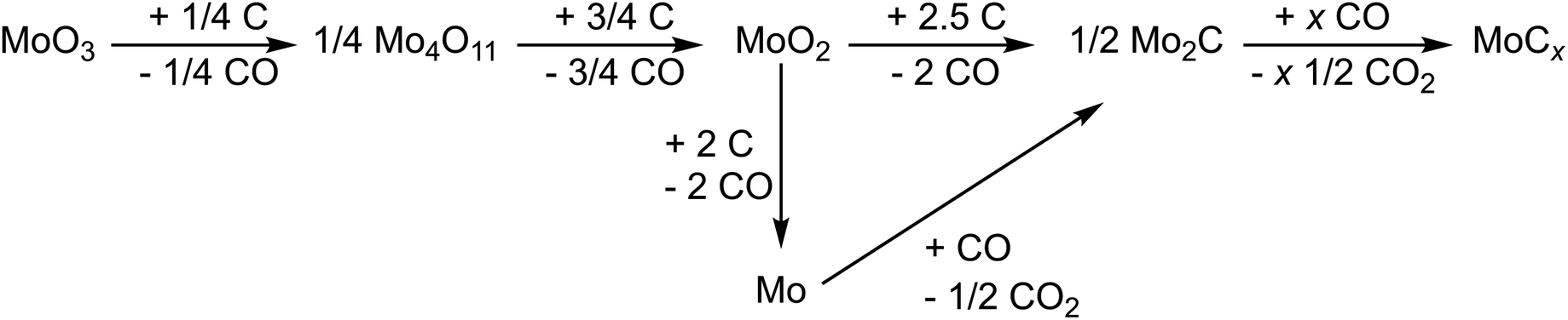
After the systematic studies regarding the synthesis and pyrolysis conditions, a range of samples with different phase compositions was chosen for the electrochemical investigations. Scanning electron microscopy (SEM) of the samples tested as LIB anodes was performed (Fig. 4). First, the samples with PPD:AHM ratio 1:1 (Fig. 4a) and 10:1 (Fig. 4b) pyrolyzed at 750 °C were investigated. Contrary to 1:1 sample the 10:1 exhibit severe stacking faults in the carbide phase and the carbon matrix.
 | ||
| Fig. 4 Scanning electron micrographs of pyrolyzed PPD/molybdate samples (a) 1:1 and (b) 10:1 pyrolyzed at 750 °C and (c) 9:1 and (d) 10:1 pyrolyzed at 600 °C. | ||
Phases with stacking faults are favored in the application as LIB materials, and the results of the investigations show that lowering the pyrolysis temperature leads to an excess of them.64 Therefore, the samples pyrolyzed at 600 °C with a PPD:AHM ratio of 9:1 (Fig. 4c) and 10:1 (Fig. 4d) were additionally examined. Although their phase composition is similar, the particles in the 9:1 sample are smaller, suggesting they could show better electrochemical performance.
4.4. Electrochemical characterization of pyrolyzed PPD/molybdate as LIB anode
The electrochemical performance of the four samples mentioned above was investigated in a LIB half-cell set-up with 1 M LiPF6 in EC:DMC (1:1 by volume) electrolyte. The results are shown in Fig. 5 and 6. The active materials were wet-coated with a conductive additive and polyvinylidene fluoride binder for electrochemical characterization. Cyclic voltammetry (CV) measurements of all materials were recorded in the voltage range from 0.01 V to 3.00 V vs. Li+/Li at different scan rates (0.10–10.00 mV s−1; Fig. 6 and ESI, Fig. S3†).
 | ||
| Fig. 5 Cyclic voltammograms of pyrolyzed PPD/molybdate hybrid materials (normalized to scan rate) recorded at different scan rates and a potential range between 0.01 V and 3.00 V vs. Li+/Li for (a) PPD/molybdate (1:1) (750 °C), (b) PPD/molybdate (10:1) (750 °C), (c) PPD/molybdate (9:1) (600 °C), and (d) PPD/molybdate (10:1) (600 °C). | ||
 | ||
| Fig. 6 Electrochemical performance of pyrolyzed PPD/molybdate hybrid materials. Galvanostatic charge and discharge profiles at an applied specific current of 100 mA g−1 between 0.01 V and 3.00 V vs. Li+/Li (a) 1:1 and (b) 10:1 pyrolyzed at 750 °C, and (c) 9:1 and (d) 10:1 synthesized at 600 °C. Galvanostatic charge/discharge cycling electrochemical performance stability with corresponding Coulombic efficiency values at a specific current of 100 mA g−1 for (e) 1:1 and 10:1 pyrolyzed at 750 °C and 9:1 and 10:1 synthesized at 600 °C. Rate performance using galvanostatic charge/discharge cycling with corresponding Coulombic efficiency at different values for the specific current for (f) 1:1 and 10:1 pyrolyzed at 750 °C, and 9:1 and 10:1 synthesized at 600 °C. | ||
The two systems containing the decomposed precursors with a PPD:AHM ratio of 1:1 and 10:1 (pyrolyzed at 750 °C) show similar peaks during cycling. For both hybrid systems, one clear reduction and one oxidation signal exist at potentials of around 1.1 V vs. Li+/Li and 1.6 V vs. Li+/Li, respectively. This mainly applies to the low scan rates up to 1.00 mV s−1. When the lithiation potential decreases from 1.50 V to 0.05 V vs. Li+/Li, the region where the conversion reaction occurs can be associated with the formation of amorphous Li2O and the full reduction of Mo.65 At high scan rates, the 10:1 sample pyrolyzed at 750 °C current level is reduced, and the curve slightly deviates from a pure capacitive-like behavior. This may indicate that the scan rate is too fast for the conversion reaction process or that the electrode degrades quickly.
The two samples with a PPD:AHM ratio of 9:1 and 10:1 pyrolyzed at 600 °C exhibit similar electrochemical behaviors, with the resulting capacity for the 9:1 sample pyrolyzed at 600 °C being significantly higher. The first cycle displays an irreversible signal at 0.7 V vs. Li+/Li, which is related to the conversion reaction and the decomposition of electrolyte and solid electrolyte interphase (SEI) formation since this signal disappears in the following cycles. MoCx shows a pseudocapacitive behavior due to its nanocrystallinity. The high performance at high rates can be partially explained by the significant contribution of a surface-limited capacitive-like process to the charge storage.
Through a kinetic analysis composed of different cyclic voltammograms collected at different scan rates, the contribution of capacitive-like charge storage can be investigated in the so-called b-value analysis. The correlation between the scan rate (v) and the current (i) can be described by the equation i = avb, with the fitting parameters represented by a and b. A b-value of 0.5 suggests an ideal charge storage process limited by diffusion, typically seen in battery-like behavior. Conversely, a b-value of 1 indicates a charge storage process limited by the surface and characteristic of electrosorption/capacitive processes.66–68 The b-value analysis performed in this work on cyclic voltammetry with scan rates between 0.1–1.0 mV s−1 is shown in ESI Fig. S4.† In the 9:1 sample that was pyrolyzed at 600 °C, the sharp lithiation/de-lithiation peak has a b-value of 0.72. In contrast, the regions at 0.50 V and 2.75 V vs. Li+/Li, which are more pseudocapacitive, demonstrate slightly higher b-values of 0.79 and 0.93, respectively. In comparison, all other samples in this study obtain a slightly lower fraction of non-diffusion limited charge storage.
The distinct signals which appear from the second cycle onward at 1.4 V vs. Li+/Li (oxidation) and 1.3 V vs. Li+/Li (reduction) can be attributed to the conversion reactions of the associated lithiation/de-lithiation of MoCx (yLi+ + MoCx + y e− → Mo + LiyCx, reaction during charging process).47,69,70 Likewise, significantly weaker reversible redox peaks occur mainly with the 9:1 sample pyrolyzed at 600 °C at about 1.2 V vs. Li+/Li, which are related to the partial embedding of the Li-ions into the MoCx lattice to form LiyMoCx.46,71 The following oxidation peak at 1.46 V vs. Li+/Li can be attributed to the oxidation from LiyMoCx to Mo and Li2O during Li+ deintercalation. Mo2C does not exhibit any electrochemical activity in the voltage range of 0.01–3.0 V vs. Li+/Li, so there are no detectable reduction or oxidation signals in the cyclic voltammograms.46
To explore the electrochemical performance and the corresponding conversion reaction of the various pyrolyzed samples, galvanostatic charge, and discharge experiments were conducted. Typically, the galvanostatic discharge and charge profiles obtained from these experiments (Fig. 6a–d) are analyzed for further insights and confirm the observations from the CV measurements. The first discharge capacities of the precursors with the PPD:AHM ratio of 1:1 and 10:1 pyrolyzed at 750 °C electrodes occur at 87.5 mA h g−1 and 123.8 mA h g−1, with an initial Coulombic efficiency of 44.7% and 65.6%, respectively. This capacity loss follows SEI film formation and insertion of Li+ into the MoCx structure. In the following cycles, one can observe a broad plateau at 1.4 V and 0.7 V vs. Li+/Li in the lithiation curve, and a clear plateau at 1.4 V vs. Li+/Li and a broad peak at 1.6 V vs. Li+/Li in the de-lithiation curve. These two charge–discharge plateaus were ambiguously found, indicating the phase transition and conversion reaction, which agrees well with the CV study above. All the plateaus observed, which are still very pronounced in the first cycles, are significantly weakened during the first 100 cycles, which indicates a changed reaction mechanism and/or rapid aging and degradation of the cell.
In comparison, the galvanostatic charge and discharge curves of precursors with a PPD:AHM ratio of 10:1 at 600 °C and 9:1 pyrolyzed at 600 °C show a discharge capacity of 148 mA h g−1 and 531 mA h g−1 with Coulombic efficiencies of 94.4% and 54.7%, respectively. The 10:1 sample pyrolyzed at 600 °C does not show a substantial plateau in the individual cycles. Instead, there is a broad plateau in the lithiation cycle at around 0.9 V vs. Li+/Li and in the de-lithiation of about 1.5 V vs. Li+/Li. The same plateaus are also observed in a slightly more pronounced form in the 9:1 sample pyrolyzed at 600 °C sample, which characterizes the lithiation process of the MoCx electrode with the associated conversion reaction. It is remarkable that at the 100th cycle, an additional plateau appears at 2.5 V vs. Li+/Li, which can also be identified in the CV analysis. So there seems to be another process responsible for slowly increasing the capacity after a certain number of cycles. The observed electrochemical signatures indicate that the fundamental electrochemical process is not significantly varied by varying the precursors and the pyrolyzing temperature. We also assume that activated carbon might have contributed slightly to the capacity.
Fig. 6f demonstrates the difference in cycling stability of all different Mo(C,N,O)x embedded in carbonaceous materials at a rate of 100 mA g−1. The lowest electrochemical performance is delivered by the 1:1 sample pyrolyzed at 750 °C, which starts with a capacity of 82 mA h g−1 and delivers around 104 mA h g−1 after 200 cycles, demonstrating a capacity gain of 25%. The 10:1 sample pyrolyzed at 750 °C, and the 10:1 sample pyrolyzed at 600 °C, offer very similar electrochemical behavior compared to the 1:1 sample pyrolyzed at 750 °C with de-lithiation capacities of 94 mA h g−1 and 154 mA h g−1 after 200 cycles combined with a capacity retention of 81% and 124%, respectively.
In contrast, the 9:1 sample pyrolyzed at 600 °C yields high electrochemical performance. The values start with an initial capacity of 531 mA h g−1, showing a capacity fading for the first 50 cycles but then rising to a capacity value of 933 mA h g−1, demonstrating capacity retention of 175% after 500 cycles. The presence of Mo2C and carbon in the hybrid materials may increase the structural stability and buffer the volume changes during the conversion reaction or lithium-ion insertion/extraction, resulting in no severe capacity degradation after 200–500 cycles.47 The hybrid material with the PPD:AHM ratio of 9:1 pyrolyzed at 600 °C indicates at this point that the structure obtained after pyrolysis is electrochemically active or is activated while cycling and thus represents a promising high-capacity material for application in LIBs.
These observations agree with the rate capability tests (Fig. 6e) and indicate that the hybrid material with the PPD:AHM ratio of 9:1 pyrolyzed at 600 °C shows volatile performance. Combined with the charge and discharge profiles, this could explain that the pre-activation or the addition in the lithiation mechanism is not achieved yet, leading to very unstable capacities during different specific currents. With significantly lower de-lithiation capacities but much more stable behavior, the precursors 1:1 and 10:1 pyrolyzed at 750 °C and the precursor 10:1 pyrolyzed at 600 °C delivered values of up to 144 mA h g−1, 115 mA h g−1 and 243 mA h g−1 with a capacity retention of 85%, 82%, and 91%, respectively when returning to the initial current. Overall, good electrochemical performance is favored by the structural defects present in the material, which significantly improves the electrical conductivity of the electrode. Likewise, the formed nanoparticle size influences the Li insertion behavior and lithium storage capacity.72–76 Smaller particle sizes of the intermediates allow a smaller lithium-ion diffusion distance and form a larger specific surface area, thus achieving a larger electrolyte–electrode material contact area. This effect may improve the kinetic properties of the system since short ion diffusion paths exist. Due to the conversion reactions occurring during cycling, free carbon is also formed from the initial material, which forms a carbon matrix. It can thus buffer the volume change during the lithiation/de-lithiation process while reducing the aggregation of Mo(C,N,O)x particles.77,78 The carbon formed can also be activated by the reactions to contribute to the electrochemical storage of the lithium ions. The high specific capacity of the 9:1 sample pyrolyzed at 600 °C can be explained by the enhanced formation of Mo4+ after lithiation, a reversible process without the evolution of the monoclinic MoO2 in the 9:1 sample pyrolyzed at 600 °C.79 In addition to the larger interlayer spacing, which favors faster kinetics, the oxygen vacancies also allow a larger physical space for lithium-ion storage to be obtained.49,80
Comparing the obtained electrochemical performances with other hybrid and composite molybdenum oxycarbides and molybdenum carbide compounds reported in the literature (Table 2), the optimized sample with the PPD:AHM ratio of 9:1 pyrolyzed at 600 °C can show favorable electrochemical performance values (e.g., 933 mA h g−1 after 500 cycles at 100 mA h g−1). The materials, optimized by a straightforward manufacturing process, can therefore keep up well with the standard of state-of-the-art literature. For example, Xiu et al. obtained with their molybdenum oxycarbide nanoparticles embedded in N-doped carbon a reversible capacity of 793 mA h g−1 only for low cycling stability (100 cycles).16 A high reversible capacity of 1188 mA h g−1 after 250 cycles at a specific current of 100 mA g−1 was reported by Yang et al. for MoO2–Mo2C–C microspheres.81 Based on a one-step annealing approach, this material delivers a similar electrochemical behavior to our data. This particularly concerns the increasing capacity while cycling, probably connected with an activation process and a change of the material and reaction mechanism, even if our material shows a slightly steeper increase in capacity after the 250 cycles than shown here. With a 2.6-fold higher capacity, our optimized system impresses, for example, compared to the molybdenum carbide embedded in carbon nanofiber as a 3D flexible anode system investigated by Lee et al. in 2018. With superior stability and high-rate performance in LIBs, performance values of 350 mA g−1 could be achieved after 300 cycles at a specific current of 500 mA g−1.82 While not showing the trend of increasing capacity during cycling, Gao et al. mesoporous Mo2C–C hybrid nanospheres system show slightly lower de-lithiation capacity with 673 mA h g−1 after 50 cycles and a cycling rate of 100 mA h g−1.69
| Material | Total electrode composition | Potential vs. Li+/Li/V | Electrolyte | Normalization | Capacity/mA h g−1 | Specific current/mA g−1 | Cycles | Ref. |
|---|---|---|---|---|---|---|---|---|
| a Data from literature sources that are not available are donated as “n.a.”. PVdF (polyvinylidene fluoride), LiPF6 (lithium hexafluoridophosphate), EC (ethylene carbonate), DMC (dimethyl carbonates), EMC (ethyl methyl carbonate, DEC (diethyl carbonate), VC (vinylene carbonate), CMC (carboxymethyl cellulose), CNT (carbon nanotubes), CNF (carbon nanofibers), rGO (reduced graphene oxide). | ||||||||
| Molybdenum oxide carbide nanoparticles embedded in N-doped carbon | Active material:SuperP:PVdF 7:2:1 |
0.01–3.00 | 1 M LiPF6 in EC/DMC (1:1 by volume) |
n.a. | 793 | 100 | 100 | Xiu et al.16 |
| Mo2C@C core–shell nanocrystals | Active material:acetylene black:sodium alginate 7:2:1 |
0.01–3.00 | 1 M LiPF6 in EC/EMC/DMC (1:1:1 by volume) |
n.a. | 1089 | 100 | 100 | Xin et al.85 |
| MoO2–Mo2C–C | MoO2–Mo2C–C:acetylene black:CMC 7:2:1 |
0.01–3.00 | 1 M LiPF6 in EC/DEC (1:1 by volume) |
n.a. | 1188 | 100 | 250 | Yang et al.81 |
| Red-blood-cell-like porous Mo2C@CNT microspheres | Active material, SuperP, PVdF 8:1:1 |
0.005–3.00 | 1 M LiPF6 in EC/DMC (1:1 by volume) |
Mo2C@CNT | 878 | 160 | 750 | Yu et al.86 |
| Reduced graphene oxide supported molybdenum carbides | Mo2 C-rGO:SuperP:PVdF 8:1:1 |
0.01–3.00 | 1 M LiPF6 in EC/DMC (1:1 by volume) |
n.a. | 856 | 100 | 400 | Chen et al.87 |
| Molybdenum carbide embedded in CNFs | n.a. | 0.01–3.00 | 1.1 M LiPF6 in EC/DMC (1:1 by volume) |
n.a. | 350 | 500 | 300 | Lee et al.82 |
| Mesoporous Mo2C–C hybrid nanospheres | Active material, carbon black, sodium alginate 6:2:2 |
0.01–3.00 | 1 M LiPF6 in EC/DEC/DMC (1:1:1 by volume) |
Mo2C and C | 673 | 100 | 50 | Gao et al.69 |
| MoO2/Mo2CTx heteromicrospheres | Active material, acetylene black, PVdF 8:1:1 |
n.a. | 1 M LiPF6 in EC/DMC (1:1 by volume + 2 wt% VC) |
n.a. | 780 | 100 | 160 | Min et al.88 |
|
PPD/molybdate (9:1) (600°C) → Mo(C,N,O)x@C |
Mo(C,N,O)
x
@C hybrid: Conductive carbon additive: PVdF 8:1:1 |
0.01–3.00 |
1 M LiPF
6
in EC/DMC (1![[thin space (1/6-em)]](https://www.rsc.org/images/entities/b_char_2009.gif) :1 by volume) :1 by volume)
|
Total hybrid | 933 | 100 | 500 | Our work |
In summary, we see good performance with low energy consumption for synthesis and the advantages of the microjet reactor. Optimizing synthesis parameters and subsequent pyrolysis at relatively low temperatures made it possible to obtain characteristic electrochemical behavior comparable to that found in the literature for different molybdenum carbides.47,83,84
4.5. Post mortem characterization of pyrolyzed PPD/molybdate LIB anodes
The electrochemical properties and structure–property correlation were better understood by comparing the cycled with untreated materials using Raman spectroscopy and XRD (Fig. 7). PXRD of the PPD:AHM ratio 1:1 pyrolyzed at 750 °C shows no significant change, which reveals no significant structural change after electrode preparation (Fig. 7b). After cycling, the powder X-ray diffractogram changes completely and could be assigned to lithium molybdate (Li2MoO4; Fig. 7b), crystallizing the trigonal crystal system with space group R (a = 1433.0(2), c = 958.4(2) pm).89
 | ||
| Fig. 7 Raman spectra of the hybrid materials (a) 1:1 and (c) 10:1 pyrolyzed at 750 °C, and (e) 9:1 and (g) 10:1 synthesized at 600 °C. X-ray diffractograms of the hybrid materials (b) 1:1 and (d) 10:1 pyrolyzed at 750 °C, and (f) 9:1 and (h) 10:1 synthesized at 600 °C. | ||
No significant changes are visible in the Raman spectra of the 10:1 sample pyrolyzed at 750 °C compared to its pristine electrode (Fig. 7c). The D-band and G-band are still present after cycling, but we see a strong fluorescence background. Small peaks in the spectra indicate the presence of the D-band and G-band (Fig. 7c). The corresponding powder X-ray diffractograms reveal a decrease in the crystallinity of the material after electrode preparation. After cycling, the amorphization of the material increases even further (Fig. 7d).
The Raman spectra of the 9:1 sample pyrolyzed at 600 °C, the corresponding pristine electrode, and the corresponding electrode after cycling all show the carbon-related D-band and G-band (Fig. 7e). X-ray diffractograms show an amorphization of the material after electrode preparation and cycling (Fig. 7f). The 10:1 samples pyrolyzed at 600 °C show similar behavior to the sample 9:1 pyrolyzed at 600 °C. The Raman spectra of the 10:1 pyrolyzed at 600 °C and the pristine electrode and the electrode after cycling show the D-band and G-band (Fig. 7g). Furthermore, a decrease in crystallinity is visible in the X-ray diffractograms (Fig. 7h). Moreover, the X-ray diffractograms of the electrodes with the ratio 10:1 pyrolyzed at 750 °C after cycling, and the samples 9:1 and 10:1 pyrolyzed at 600 °C show a decrease of the intensity of the reflection at ∼37° 2θ, which belongs to the carbide. Nevertheless, several peaks appear in the electrode materials due to the electrode preparation, where PVdF as a binder and carbon black is involved. Furthermore, after cycling, electrolyte components can be detected.90
X-ray photoelectron spectroscopy (XPS) was conducted to provide information on the Mo species' oxidation states, oxygen bonding states, and carbon bonding states. Four components were used to fit the Mo 3d peaks (Fig. 8a–c). The Mo6+ species has the maximum binding energy (BE) with a BE of 232.6(2) eV. Mo5+ with a constant binding energy distance of −1.3 eV was fitted to Mo6+, while Mo4+ with a constant binding energy distance of −3 eV was fitted to the Mo6+ binding energy. The Mo-carbides were fitted with a BE of 228.5(3) eV.91 There were four components to fit the O 1s peaks (Fig. 8d–f). The signal at 530.6 eV was used for calibration, which is caused by the O–Mo6+ interaction. At a binding energy of 531.2 eV, the O–Mo5+ contribution was detected. The binding energies attributed to the O![[double bond, length as m-dash]](https://www.rsc.org/images/entities/char_e001.gif) C and O–Mo4+ bonds overlap at 532.0 eV, and the O–C-bond-derived contribution has a binding energy of 533.3 eV.91 The C 1s peaks were fitted with eight components (Fig. 8g–i). The carbide carbon (Mo–C) was fitted with a binding energy of 283.4(1) eV. The oxide carbide carbon (C–Mo–O) was fitted at 283.9(1) eV. Graphitic carbon (C–C sp2) is seen at 284.3(1) eV, and amorphous carbon (aliphatic C–C sp3) is observed at 284.8(1) eV. The binding energies of C–OH/R were found at 286.5(1) eV and CO at 288.4(1) eV.92,93 Additionally, the electrode material bonding of Cx–Fy is visible, which partially overlapped. The binding energy of C–CF is 285.7 eV, the one of CO/C–CF2 is 287.7 eV, and the one of CFx/CO3 is at 290.1 eV.94 In all cases, the precursor with the PPD:AHM ratio of 9:1 pyrolyzed at 600 °C electrode after cycling was compared with its pristine electrode.
C and O–Mo4+ bonds overlap at 532.0 eV, and the O–C-bond-derived contribution has a binding energy of 533.3 eV.91 The C 1s peaks were fitted with eight components (Fig. 8g–i). The carbide carbon (Mo–C) was fitted with a binding energy of 283.4(1) eV. The oxide carbide carbon (C–Mo–O) was fitted at 283.9(1) eV. Graphitic carbon (C–C sp2) is seen at 284.3(1) eV, and amorphous carbon (aliphatic C–C sp3) is observed at 284.8(1) eV. The binding energies of C–OH/R were found at 286.5(1) eV and CO at 288.4(1) eV.92,93 Additionally, the electrode material bonding of Cx–Fy is visible, which partially overlapped. The binding energy of C–CF is 285.7 eV, the one of CO/C–CF2 is 287.7 eV, and the one of CFx/CO3 is at 290.1 eV.94 In all cases, the precursor with the PPD:AHM ratio of 9:1 pyrolyzed at 600 °C electrode after cycling was compared with its pristine electrode.
 | ||
| Fig. 8 Fitted XPS Mo 3d spectra of the (a) PPD/molybdate with a PPD:AHM ratio of 9:1 pyrolyzed at 600 °C, (b) pristine electrode, (c) electrode after cycling. Fitted XPS O 1s spectra of the (d) PPD/molybdate with a PPD:AHM ratio of 9:1 pyrolyzed at 600 °C, (e) pristine electrode, (f) electrode after cycling. Fitted XPS C 1s spectra, (g) PPD/molybdate with a PPD:AHM ratio of 9:1 pyrolyzed at 600 °C, (h) pristine electrode, and (i) electrode after cycling. | ||
The shallow signal depth of XPS of about 10 nm favors information from the interfacial/superficial SEI layer. A comparison of the Mo 3d spectra of the precursor with the PPD:AHM ratio of 9:1 pyrolyzed at 600 °C (Fig. 8a) with the pristine electrode (Fig. 8b) shows no significant change. The only difference is that the Mo carbide content decreases slightly while the Mo6+ increases slightly. A major change is visible after cycling (Fig. 8c). The content of Mo6+, Mo5+, and Mo4+ increases while the Mo-carbide decreases enormously. The O 1s spectra show a decrease in the O–Mo6+ content and an increase of the OC/O–Mo4+ content from the precursor with the PPD:AHM ratio of 9:1 pyrolyzed at 600 °C (Fig. 8d) to the pristine electrode (Fig. 8e) or the electrode after cycling (Fig. 8f). In the C 1s spectra of the precursor with the PPD:AHM ratio of 9:1 pyrolyzed at 600 °C (Fig. 8g), both carbide (Mo–C) and oxycarbides (C–Mo–O), CO, C–C sp2, and aliphatic C–C sp3 are visible. In the pristine electrode (Fig. 8h) and the electrode after cycling (Fig. 8i), CFx appears due to the polymer binder PVdF added to the material during electrode fabrication. In addition, the peak of aliphatic C–C sp3 increases because carbon black was also added during electrode fabrication. The increase of the signal sp2 C–C– binding energy confirms the above assumptions that the carbon matrix increases.
The XPS data indicates a complex process occurs during the electrode preparation and cycling. The Mo-carbide peak vanishes in the Mo 3d spectra, consistent with the XRD data. A shift in the relative ratios of the O–Mo peaks indicates a reduction from O–Mo6+ to O–Mo4+.
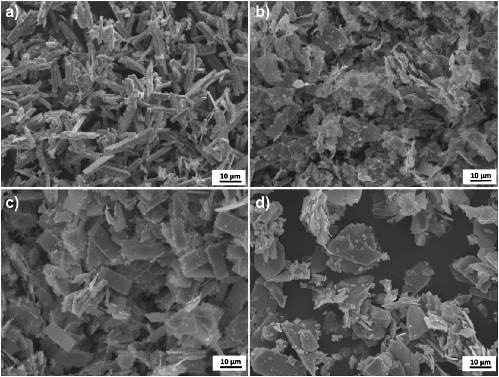
Scanning electron micrographs of the original electrode (Fig. 9a) and the electrode after cycling (Fig. 9b) were performed to confirm the assumption that two processes (decomposition of the carbide and the reduction of O–Mo6+) occur during cycling leading to the formation of two products. In the pristine electrode, the initially present sheet-like morphology originating from the precursor with the PPD:AHM ratio of 9:1 pyrolyzed at 600 °C can be seen. In addition, a homogeneous distribution of the carbon black particles is observed. The electrode additionally shows particles with a fibrous morphology after cycling. This underlines the assumption that a lithium-ion insertion/extraction and a conversion reaction must occur during the electrochemical cycling.
 | ||
| Fig. 9 Scanning electron micrographs of the PPD/molybdate with a PPD:AHM ratio of 9:1 pyrolyzed at 600 °C, (a) pristine electrode, and (b) electrode after cycling. | ||
5. Conclusions
In this study, we investigated the effects of synthesis conditions for synthesizing inorganic–organic hybrid materials from ammonium heptamolybdate (AHM) and para-phenylenediamine (PPD) by a wet chemical continuous precipitation microjet method. In the second step, these served as precursors for the pyrolytic production of molybdenum carbides, nitrides, and oxides. Our data show the crucial role of the proportions of the organic component in the hybrid precursors. The precursors with lower PPD content resulted in a mixture of Mo2C, MoO2, Mo2N, and elemental Mo. These materials do not exhibit stacking defects and excess carbon, which was shown to be crucial for improving electrochemical performance. Precursors with higher PPD content led to Mo(C,N,O)x with stacking defects embedded in a carbonaceous matrix, a potential anode with high capacity and cycling stability. The electrochemical measurements showed that different morphologies and particle sizes could be obtained by different synthesis parameters and pyrolysis temperature settings, resulting in different electrochemical behaviors. For example, the precursor with a PPD:AHM ratio of 9:1 was pyrolyzed at 600 °C and exhibited capacities up to 933 mA h g1 after 500 cycles. Further investigation showed that two processes, decomposition of the carbide and reduction of O–Mo6+ occur during cycling. We assume that lithium storage/removal and a conversion reaction occur during electrochemical cycling, resulting in an improved electrochemical performance with high cycling stability.
Author contributions
Mana Abdirahman Mohamed: materials synthesis, measurements, data analysis, writing, plotting, discussion, and manuscript revision. Stefanie Arnold: electrochemical measurements, writing, plotting, discussion, Raman measurements, and manuscript revision. Oliver Janka: discussion, analysis of the PXRD data and manuscript revision. Antje Quade: XPS measurement, plotting, discussion, and manuscript revision. Jörg Schmauch: acquisition of HR-TEM and TEM images and determination of lattice plane distances. Volker Presser: supervision, discussion, and manuscript revision. Guido Kickelbick: conceptualization, supervision, project administration, discussion, and manuscript revision.Conflicts of interest
There are no conflicts to declare.Acknowledgements
Instrumentation and technical assistance for this work were provided by the Service Center X-ray Diffraction, with financial support from Saarland University and German Science Foundation (project number INST 256/349-1). We thank Dr Robert Haberkorn (Saarland University) for the helpful discussion and advice regarding the Rietveld refinements. Special thanks also to Susanne Harling (Saarland University) for conducting the elemental analyses.References
- S. Chu and A. Majumdar, Opportunities and Challenges for a Sustainable Energy Future, Nature, 2012, 488, 294–303, DOI:10.1038/nature11475.
- M. Weiss, R. Ruess, J. Kasnatscheew, Y. Levartovsky, N. R. Levy, P. Minnmann, L. Stolz, T. Waldmann, M. Wohlfahrt-Mehrens, D. Aurbach, M. Winter, Y. Ein-Eli and J. Janek, Fast Charging of Lithium-Ion Batteries : A Review of Materials Aspects, Adv. Energy Mater., 2021, 11, 1–37, DOI:10.1002/aenm.202101126.
- Y. Gao, X. I. Zhang, Q. Cheng, B. Guo and J. Yang, Classification and Review of the Charging Strategies for Commercial Lithium-Ion Batteries, IEEE Access, 2019, 7, 43511–43524, DOI:10.1109/ACCESS.2019.2906117.
- H. Zhang, Y. Yang, D. Ren, L. Wang and X. He, Graphite as Anode Materials: Fundamental Mechanism, Recent Progress and Advances, Energy Storage Mater., 2021, 36, 147–170, DOI:10.1016/j.ensm.2020.12.027.
- J. Asenbauer, T. Eisenmann, M. Kuenzel, A. Kazzazi, Z. Chen and D. Bresser, The Success Story of Graphite as a Lithium-Ion Anode Material-Fundamentals, Remaining Challenges, and Recent Developments Including Silicon (Oxide) Composites, Sustain. Energy Fuels, 2020, 4, 5387–5416, 10.1039/d0se00175a.
- L. Lu, X. Han, J. Li, J. Hua and M. Ouyang, A Review on the Key Issues for Lithium-Ion Battery Management in Electric Vehicles, J. Power Sources, 2013, 226, 272–288, DOI:10.1016/j.jpowsour.2012.10.060.
- V. Etacheri, R. Marom, R. Elazari, G. Salitra and D. Aurbach, Challenges in the Development of Advanced Li-Ion Batteries: A Review, Energy Environ. Sci., 2011, 4, 3243–3262, 10.1039/c1ee01598b.
- A. Pan, H. B. Wu, L. Yu, T. Zhu and X. W. Lou, Synthesis of Hierarchical Three-Dimensional Vanadium Oxide Microstructures as High-Capacity Cathode Materials for Lithium-Ion Batteries, ACS Appl. Mater. Interfaces, 2012, 4, 3874–3879, DOI:10.1021/am3012593.
- C. F. Armer, J. S. Yeoh, X. Li and A. Lowe, Electrospun Vanadium-Based Oxides as Electrode Materials, J. Power Sources, 2018, 395, 414–429, DOI:10.1016/j.jpowsour.2018.05.076.
- S. B. Patil, Udayabhanu, B. Kishore, G. Nagaraju and J. Dupont, High Capacity MoO3/RGO Nanocomposite Anode for Lithium Ion Batteries: An Intuition into the Conversion Mechanism of MoO3, New J. Chem., 2018, 42, 18569–18577, 10.1039/c8nj03190h.
- H. Zhang, L. Gao and Y. Gong, Exfoliated MoO3 Nanosheets for High-Capacity Lithium Storage, Electrochem. Commun., 2015, 52, 67–70, DOI:10.1016/j.elecom.2015.01.014.
- J. Ni, G. Wang, J. Yang, D. Gao, J. Chen, L. Gao and Y. Li, Carbon Nanotube-Wired and Oxygen-Deficient MoO3 Nanobelts with Enhanced Lithium-Storage Capability, J. Power Sources, 2014, 247, 90–94, DOI:10.1016/j.jpowsour.2013.08.068.
- J. J. Auborn and Y. L. Barberio, Lithium Intercalation Cells Without Metallic Lithium: MoO2/LiCoO2 and WO2/LiCoO2, J. Electrochem. Soc., 1987, 134, 638, DOI:10.1149/1.2100521.
- A. Manthiram and C. Tsang, Synthesis of Amorphous MoO2+δ and Its Electrode Performance in Lithium Batteries, J. Electrochem. Soc., 1996, 143, L143, DOI:10.1149/1.1836955.
- Z. Wang, J. S. Chen, T. Zhu, S. Madhavi and X. W. Lou, One-Pot Synthesis of Uniform Carbon-Coated MoO2 Nanospheres for High-Rate Reversible Lithium Storage, Chem. Commun., 2010, 46, 6906–6908, 10.1039/c0cc01174f.
- Z. Xiu, D. Kim, M. H. Alfaruqi, J. Song, S. Kim, P. T. Duong, V. Mathew, J. P. Baboo and J. Kim, Ultrafine Molybdenum Oxycarbide Nanoparticles Embedded in N-Doped Carbon as a Superior Anode Material for Lithium-Ion Batteries, J. Alloys Compd., 2017, 696, 143–149, DOI:10.1016/j.jallcom.2016.11.235.
- H. Preiss, B. Meyer and C. Olschewski, Preparation of Molybdenum and Tungsten Carbides from Solution Derived Precursors, J. Mater. Sci., 1998, 713–722, DOI:10.1023/A:1004393813199.
- L. Liao, S. Wang, J. Xiao, X. Bian, Y. Zhang, M. D. Scanlon, X. Hu, Y. Tang, B. Liu and H. H. Girault, A Nanoporous Molybdenum Carbide Nanowire as an Electrocatalyst for Hydrogen Evolution Reaction, Energy Environ. Sci., 2014, 7, 387–392, 10.1039/c3ee42441c.
- C. Ge, P. Jiang, W. Cui, Z. Pu, Z. Xing, A. M. Asiri, A. Y. Obaid, X. Sun and J. Tian, Shape-Controllable Synthesis of Mo2C Nanostructures as Hydrogen Evolution Reaction Electrocatalysts with High Activity, Electrochim. Acta, 2014, 134, 182–186, DOI:10.1016/j.electacta.2014.04.113.
- M. Pang, X. Wang, W. Xia, M. Muhler and C. Liang, Mo(VI)-Melamine Hybrid As Single-Source Precursor to Pure-Phase β-Mo2C for the Selective Hydrogenation of Naphthalene to Tetralin, Ind. Eng. Chem. Res., 2013, 52, 4564–4571, DOI:10.1021/ie400119d.
- Y. Liu, G. Yu, G.-D. Li, Y. Sun, T. Asefa, W. Chen and X. Zou, Coupling Mo2C with Nitrogen-Rich Nanocarbon Leads to Efficient Hydrogen-Evolution Electrocatalytic Sites, Angew. Chem., 2015, 127, 10902–10907, DOI:10.1002/ange.201504376.
- C. Giordano, C. Erpen, W. Yao and M. Antonietti, Synthesis of Mo and W Carbide and Nitride Nanoparticles via a Simple “Urea Glass” Route, Nano Lett., 2008, 8, 4659–4663, DOI:10.1021/nl8018593.
- Y. Huang, Q. Gong, X. Song, K. Feng, K. Nie, F. Zhao, Y. Wang, M. Zeng, J. Zhong and Y. Li, Mo2C Nanoparticles Dispersed on Hierarchical Carbon Microflowers for Efficient Electrocatalytic Hydrogen Evolution, ACS Nano, 2016, 10, 11337–11343, DOI:10.1021/acsnano.6b06580.
- S. Li, C. Cheng, A. Sagaltchik, P. Pachfule, C. Zhao and A. Thomas, Metal-Organic Precursor–Derived Mesoporous Carbon Spheres with Homogeneously Distributed Molybdenum Carbide/Nitride Nanoparticles for Efficient Hydrogen Evolution in Alkaline Media, Adv. Funct. Mater., 2019, 29, 1–10, DOI:10.1002/adfm.201807419.
- H.-M. Wang, X.-H. Wang, M.-H. Zhang, X.-Y. Du, W. Li and K.-Y. Tao, Synthesis of Bulk and Supported Molybdenum Carbide by a Single-Step Thermal Carburization Method, Chem. Mater., 2007, 19, 1801–1807, DOI:10.1021/cm0615471.
- M. A. Mohamed, S. Arnold, O. Janka, A. Quade, V. Presser and G. Kickelbick, Self-Activation of Inorganic-Organic Hybrids Derived through Continuous Synthesis of Polyoxomolybdate and Para-Phenylenediamine Enables Very High Lithium-Ion Storage Capacity, ChemSusChem, 2023, 16, 1–15, DOI:10.1002/cssc.202202213.
- M. Zoller, R. Bubnova, Y. Biryukov, E. Haussühl, R. Pöttgen, O. Janka, S. Penner, C. Praty, H. Fitzek, J. Winkler, S. Filatov and H. Huppertz, Elucidating the Physical Properties of the Molybdenum Oxide Mo4O11 and Its Tantalum Substituted Variant Mo2Ta2O11, Z. Kristallogr., 2020, 235, 143–155, DOI:10.1515/zkri-2019-0073.
- O. Glemser and G. Lutz, Über Molybdänoxyde, Z. Anorg. Allg. Chem., 1950, 263, 2–14 CrossRef CAS.
- E. Parthé and V. Sadogopan, The Structure of Dimolybdenum Carbide by Neutron Diffraction Technique, Acta Crystallogr., 1963, 16, 202–205, DOI:10.1107/s0365110x63000487.
- A. W. Hull, The Positions of Atoms in Metals, Proc. Am. Inst. Electr. Eng., 1919, 38, 1171–1192, DOI:10.1109/T-AIEE.1919.4765642.
- W.-F. Chen, C.-H. Wang, K. Sasaki, N. Marinkovic, W. Xu, J. T. Muckerman, Y. Zhu and R. R. Adzic, Highly Active and Durable Nanostructured Molybdenum Carbide Electrocatalysts for Hydrogen Production, Energy Environ. Sci., 2013, 6, 943–951, 10.1039/c2ee23891h.
- H. Zhu, Z. Li, H. Yang and L. Luo, Carbothermic Reduction of MoO3 for Direct Alloying Process, J. Iron Steel Res. Int., 2013, 20, 51–56, DOI:10.1016/S1006-706X(13)60176-4.
- C. Odenwald and G. Kickelbick, Additive-Free Continuous Synthesis of Silica and ORMOSIL Micro- and Nanoparticles Applying a Microjet Reactor, J. Sol-Gel Sci. Technol., 2019, 89, 343–353, DOI:10.1007/s10971-018-4626-x.
- A. Betke and G. Kickelbick, Bottom-Up, Wet Chemical Technique for the Continuous Synthesis of Inorganic Nanoparticles, Inorganics, 2014, 2, 1–15, DOI:10.3390/inorganics2010001.
- B. Krüner, C. Odenwald, A. Tolosa, A. Schreiber, M. Aslan, G. Kickelbick and V. Presser, Carbide-Derived Carbon Beads with Tunable Nanopores from Continuously Produced Polysilsesquioxanes for Supercapacitor Electrodes, Sustain. Energy Fuels, 2017, 1, 1588–1600, 10.1039/c7se00265c.
- B. Krüner, C. Odenwald, N. Jäckel, A. Tolosa, G. Kickelbick and V. Presser, Silicon Oxycarbide Beads from Continuously Produced Polysilsesquioxane as Stable Anode Material for Lithium-Ion Batteries, ACS Appl. Energy Mater., 2018, 1, 2961–2970, DOI:10.1021/acsaem.8b00716.
- B. Krüner, C. Odenwald, A. Quade, G. Kickelbick and V. Presser, Influence of Nitrogen-Doping for Carbide-Derived Carbons on the Supercapacitor Performance in an Organic Electrolyte and an Ionic Liquid, Batter. Supercaps, 2018, 1, 135–148, DOI:10.1002/batt.201800051.
- A. X. S. Bruker and G. Karlsruhe, Topas 5.1. General Profile and Structure Analysis Software for Powder Diffraction Data, 2014 Search PubMed.
- K. Pfeifer, S. Arnold, J. Becherer, C. Das, J. Maibach, H. Ehrenberg and S. Dsoke, Can Metallic Sodium Electrodes Affect the Electrochemistry of Sodium-Ion Batteries? Reactivity Issues and Perspectives, ChemSusChem, 2019, 12, 3312–3319, DOI:10.1002/cssc.201901056.
- M. Wang, X. Dong, I. C. Escobar and Y. T. Cheng, Lithium Ion Battery Electrodes Made Using Dimethyl Sulfoxide (DMSO) - A Green Solvent, ACS Sustain. Chem. Eng., 2020, 8, 11046–11051, DOI:10.1021/acssuschemeng.0c02884.
- H. W. Hugosson, O. Eriksson, L. Nordström, U. Jansson, L. Fast, A. Delin, J. M. Wills and B. Johansson, Theory of Phase Stabilities and Bonding Mechanisms in Stoichiometric and Substoichiometric Molybdenum Carbide, J. Appl. Phys., 1999, 86, 3758–3767, DOI:10.1063/1.371284.
- K. Kuo and G. Hägg, A New Molybdenum Carbide, Nature, 1952, 170, 245–246 CrossRef CAS.
- E. Rudy and F. Benesovsky, Untersuchungen Im System Vanadin-Molybdän-Kohlenstoff Stabilisierung Des Kubischen Molybdänkarbids, Planseeber. für Pulvermetall., 1962, 10, 42–64 CAS.
- A. Westgren and G. Phragmén, Röntgenanalyse Der Systeme Wolfram-Kohlenstoff Und Molybdän-Kohlenstoff, Z. Anorg. Allg. Chem., 1926, 156, 27–36 CrossRef CAS.
- S. T. Oyama, Preparation and Catalytic Properties of Transition Metal Carbides and Nitrides, Catal. Today, 1992, 15, 179–200, DOI:10.1016/0920-5861(92)80175-M.
- H.-J. Zhang, K.-X. Wang, X.-Y. Wu, Y.-M. Jiang, Y.-B. Zhai, C. Wang, X. Wei and J.-S. Chen, MoO2/Mo2C Heteronanotubes Function as High-Performance Li-Ion Battery Electrode, Adv. Funct. Mater., 2014, 24, 3399–3404, DOI:10.1002/adfm.201303856.
- T. Chen, X. Yan, Z. Ma, Y. Zhang, X. Zheng and Y. Jiang, A General Method to Synthesize a MoC/C Composite Material with Potential Application as an Anodic Material in Lithium-Ion Batteries, Ionics, 2020, 26, 4869–4875, DOI:10.1007/s11581-020-03633-2.
- L. Gurusamy, G.-J. Lee, S. Anandan, N. Liu and J. J. Wu, Fabrication of Molybdenum Oxycarbide Nanoparticles Dispersed on Nitrogen-Doped Carbon Hollow Nanotubes through Anion Exchange Mechanism for Enhanced Performance in Supercapacitor, J. Energy Storage, 2020, 27, 1–13, DOI:10.1016/j.est.2019.101122.
- J. Zhang, L. Zhang, J. Zhang, Z. Zhang and Z. Wu, Effect of Surface/Bulk Oxygen Vacancies on the Structure and Electrochemical Performance of TiO2 Nanoparticles, J. Alloys Compd., 2015, 642, 28–33, DOI:10.1016/j.jallcom.2015.04.096.
- P. Ettmayer, Das System Molybdaen-Stickstoff, Monatsh. Chem., 1970, 101, 127–140 CrossRef CAS.
- A. Norlund Christensen, A Neutron Diffraction Investigation on a Crystal of Alpha-Mo2C, Acta Chem. Scand., 1977, 31, 509–511 CrossRef.
- J. Häglund, A. Fernndez Guillermet, G. Grimvall and M. Körling, Theory of Bonding in Transition-Metal Carbides and Nitrides, Phys. Rev. B: Condens. Matter Mater. Phys., 1993, 48, 11685–11691, DOI:10.1103/PhysRevB.48.11685.
- E. Rudy, C. E. Brukl and S. Windisch, Constitution of Niobium (Columbium)-Molybdenum-Carbon Alloys, Trans. Metall. Soc. AIME, 1967, 239, 1796–1808 CAS.
- U. Wolf, F. Ernst, T. Muschik, M. W. Finnis and H. F. Fischmeister, The Influence of Grain Boundary Inclination on the Structure and Energy of σ = 3 Grain Boundaries in Copper, Philos. Mag. A, 1992, 66, 991–1016, DOI:10.1080/01418619208248003.
- D. Hofmann and F. Ernst, Quantitative High-Resolution Transmission Electron Microscopy of the Incoherent Σ3 (211) Boundary in Cu, Ultramicroscopy, 1994, 53, 205–221, DOI:10.1016/0304-3991(94)90035-3.
- G. H. Campbell, D. K. Chan, D. L. Medlin, J. E. Angelo and C. B. Carter, Dynamic Observation of the FCC to 9R Shear Transformation in a Copper Σ = 3 Incoherent Twin Boundary, Scr. Mater., 1996, 35, 837–842, DOI:10.1016/1359-6462(96)00220-5.
- D. L. Medlin, G. H. Campbell and C. B. Carter, Stacking Defects in the 9R Phase at an Incoherent Twin Boundary in Copper, Acta Mater., 1998, 46, 5135–5142, DOI:10.1016/S1359-6454(98)00164-5.
- A. A. Bolzan, B. J. Kennedy and C. J. Howard, Neutron Powder Diffraction Study of Molybdenum and Tungsten Dioxides, Aust. J. Chem., 1995, 48, 1473–1477 CrossRef CAS.
- R. Wang, J. Yang, K. Shi, B. Wang, L. Wang, G. Tian, B. Bateer, C. Tian, P. Shen and H. Fu, Single-Step Pyrolytic Preparation of Mo2C/Graphitic Carbon Nanocomposite as Catalyst Carrier for the Direct Liquid-Feed Fuel Cells, RSC Adv., 2013, 3, 4771–4777, 10.1039/c3ra23391j.
- Y.-Y. Chen, Y. Zhang, W.-J. Jiang, X. Zhang, Z. Dai, L.-J. Wan and J.-S. Hu, Pomegranate-like N,P-Doped Mo2C@C Nanospheres as Highly Active Electrocatalysts for Alkaline Hydrogen Evolution, ACS Nano, 2016, 10, 8851–8860, DOI:10.1021/acsnano.6b04725.
- A. C. Ferrari and J. Robertson, Interpretation of Raman Spectra of Disordered and Amorphous Carbon, Phys. Rev. B, 1999, 61, 14095–14107, DOI:10.1103/PhysRevB.61.14095.
- R. Srivastava and L. L. Chase, Raman Spectra of CrO2 and MoO2 Single Crystals, Solid State Commun., 1972, 11, 349–353 CrossRef CAS.
- L. Kumari, Y.-R. Ma, C.-C. Tsai, Y.-W. Lin, S. Y. Wu, K.-W. Cheng and Y. Liou, X-Ray Diffraction and Raman Scattering Studies on Large-Area Array and Nanobranched Structure of 1D MoO2 Nanorods, Nanotechnology, 2007, 18, 1–7, DOI:10.1088/0957-4484/18/11/115717.
- R. Shunmugasundaram, R. S. Arumugam and J. R. Dahn, A Study of Stacking Faults and Superlattice Ordering in Some Li-Rich Layered Transition Metal Oxide Positive Electrode Materials, J. Electrochem. Soc., 2016, 163, A1394–A1400, DOI:10.1149/2.1221607jes.
- J. S. Chen, Y. L. Cheah, S. Madhavi and X. W. Lou, Fast Synthesis of α-MoO3 Nanorods with Controlled Aspect Ratios and Their Enhanced Lithium Storage Capabilities, J. Phys. Chem. C, 2010, 114, 8675–8678, DOI:10.1021/jp1017482.
- V. Augustyn, J. Come, M. A. Lowe, J. W. Kim, P.-L. Taberna, S. H. Tolbert, H. D. Abruña, P. Simon and B. Dunn, High-Rate Electrochemical Energy Storage through Li+ Intercalation Pseudocapacitance, Nat. Mater., 2013, 12, 518–522, DOI:10.1038/nmat3601.
- S. Fleischmann, J. B. Mitchell, R. Wang, C. Zhan, D. E. Jiang, V. Presser and V. Augustyn, Pseudocapacitance: From Fundamental Understanding to High Power Energy Storage Materials, Chem. Rev., 2020, 120, 6738–6782, DOI:10.1021/acs.chemrev.0c00170.
- S. Ardizzone, G. Fregonara and S. Trasatti, “Inner” and “Outer” Active Surface of RuO2 Electrodes, Electrochim. Acta, 2002, 35, 263–267, DOI:10.1016/0013-4686(90)85068-X.
- Q. Gao, X. Zhao, Y. Xiao, D. Zhao and M. Cao, A Mild Route to Mesoporous Mo2C-C Hybrid Nanospheres for High Performance Lithium-Ion Batteries, Nanoscale, 2014, 6, 6151–6157, 10.1039/c3nr06678a.
- M. Li, S. Yu, Z. Chen, Z. Wang, F. Lv, B. Nan, Y. Zhu, Y. Shi, W. Wang, S. Wu, H. Liu, Y. Tang and Z. Lu, MoC Ultrafine Nanoparticles Confined in Porous Graphitic Carbon as Extremely Stable Anode Materials for Lithium- and Sodium-Ion Batteries, Inorg. Chem. Front., 2017, 4, 289–295, 10.1039/c6qi00465b.
- J. Ni, Y. Zhao, L. Li and L. Mai, Ultrathin MoO2 Nanosheets for Superior Lithium Storage, Nano Energy, 2015, 11, 129–135, DOI:10.1016/j.nanoen.2014.10.027.
- C. H. Lu and S. W. Lin, Influence of the Particle Size on the Electrochemical Properties of Lithium Manganese Oxide, J. Power Sources, 2001, 97(98), 458–460, DOI:10.1016/S0378-7753(01)00637-1.
- I. Hwang, C. W. Lee, J. C. Kim and S. Yoon, Particle Size Effect of Ni-Rich Cathode Materials on Lithium Ion Battery Performance, Mater. Res. Bull., 2012, 47, 73–78, DOI:10.1016/j.materresbull.2011.10.002.
- X. Su, Q. Wu, J. Li, X. Xiao, A. Lott, W. Lu, B. W. Sheldon and J. Wu, Silicon-Based Nanomaterials for Lithium-Ion Batteries: A Review, Adv. Energy Mater., 2014, 4, 1–23, DOI:10.1002/aenm.201300882.
- I. Capone, K. Hurlbutt, A. J. Naylor, A. W. Xiao and M. Pasta, Effect of the Particle-Size Distribution on the Electrochemical Performance of a Red Phosphorus-Carbon Composite Anode for Sodium-Ion Batteries, Energy Fuel., 2019, 33, 4651–4658, DOI:10.1021/acs.energyfuels.9b00385.
- H. Choi, A. R. Schuer, H. Moon, M. Kuenzel and S. Passerini, Investigating the Particle Size Effect on the Electrochemical Performance and Degradation of Cobalt-Free Lithium-Rich Layered Oxide Li1.2Ni0.2Mn0.6O2, Electrochim. Acta, 2022, 430, 141047, DOI:10.1016/j.electacta.2022.141047.
- R. Zhou, H. Guo, Y. Yang, Z. Wang, X. Li and Y. Zhou, N-Doped Carbon Layer Derived from Polydopamine to Improve the Electrochemical Performance of Spray-Dried Si/Graphite Composite Anode Material for Lithium Ion Batteries, J. Alloys Compd., 2016, 689, 130–137, DOI:10.1016/j.jallcom.2016.07.315.
- S. Goriparti, E. Miele, F. De Angelis, E. Di Fabrizio, R. Proietti Zaccaria and C. Capiglia, Review on Recent Progress of Nanostructured Anode Materials for Li-Ion Batteries, J. Power Sources, 2014, 257, 421–443, DOI:10.1016/j.jpowsour.2013.11.103.
- H. S. Kim, J. B. Cook, H. Lin, J. S. Ko, S. H. Tolbert, V. Ozolins and B. Dunn, Oxygen Vacancies Enhance Pseudocapacitive Charge Storage Properties of MoO3-X, Nat. Mater., 2017, 16, 454–462, DOI:10.1038/NMAT4810.
- J. Qiu, C. Lai, E. Gray, S. Li, S. Qiu, E. Strounina, C. Sun, H. Zhao and S. Zhang, Blue Hydrogenated Lithium Titanate as a High-Rate Anode Material for Lithium-Ion Batteries, J. Mater. Chem. A, 2014, 2, 6353–6358, 10.1039/c4ta00556b.
- X. Yang, Q. Li, H. Wang, J. Feng, M. Zhang, R. Yuan and Y. Chai, In-Situ Carbonization for Template-Free Synthesis of MoO2-Mo2C-C Microspheres as High-Performance Lithium Battery Anode, Chem. Eng. J., 2018, 337, 74–81, DOI:10.1016/j.cej.2017.12.072.
- G. H. Lee, S. H. Moon, M. C. Kim, S. J. Kim, S. Choi, E. S. Kim, S. B. Han and K. W. Park, Molybdenum Carbide Embedded in Carbon Nanofiber as a 3D Flexible Anode with Superior Stability and High-Rate Performance for Li-Ion Batteries, Ceram. Int., 2018, 44, 7972–7977, DOI:10.1016/j.ceramint.2018.01.237.
- M. Ihsan, H. Wang, S. R. Majid, J. Yang, S. J. Kennedy, Z. Guo and H. K. Liu, MoO2/Mo2C/C Spheres as Anode Materials for Lithium Ion Batteries, Carbon, 2016, 96, 1200–1207, DOI:10.1016/j.carbon.2015.10.076.
- Y. Zhu, S. Wang, Y. Zhong, R. Cai, L. Li and Z. Shao, Facile Synthesis of a MoO2-Mo2C-C Composite and Its Application as Favorable Anode Material for Lithium-Ion Batteries, J. Power Sources, 2016, 307, 552–560, DOI:10.1016/j.jpowsour.2016.01.014.
- H. Xin, Y. Hai, D. Li, Z. Qiu, Y. Lin, B. Yang, H. Fan and C. Zhu, Coupling Mo2C@C Core-Shell Nanocrystals on 3D Graphene Hybrid Aerogel for High-Performance Lithium Ion Battery, Appl. Surf. Sci., 2018, 441, 69–76, DOI:10.1016/j.apsusc.2018.01.187.
- B. Yu, D. Yang, Y. Hu, J. He, Y. Chen and W. He, Mo2C Nanodots Anchored on N-Doped Porous CNT Microspheres as Electrode for Efficient Li-Ion Storage, Small Methods, 2019, 3, 1–7, DOI:10.1002/smtd.201800287.
- M. Chen, J. Zhang, Q. Chen, M. Qi and X. Xia, Construction of Reduced Graphene Oxide Supported Molybdenum Carbides Composite Electrode as High-Performance Anode Materials for Lithium Ion Batteries, Mater. Res. Bull., 2016, 73, 459–464, DOI:10.1016/j.materresbull.2015.09.030.
- J. Min, K. Wang, J. Liu, Y. Yao, W. Wang, L. Yang, R. Zhang and M. Lei, Facile Synthesis of Uniform MoO2/Mo2CTX Heteromicrospheres as High-Performance Anode Materials for Lithium-Ion Batteries, J. Power Sources, 2017, 363, 392–403, DOI:10.1016/j.jpowsour.2017.07.079.
- U. Kolitsch, The Crystal Structures of Phenacite-Type Li2(MoO4), and Scheelite-Type LiY(MoO4)2 and LiNd(MoO4)2, Z. Kristallogr., 2001, 216, 449–454, DOI:10.1524/zkri.216.8.449.20358.
- A. Krause, O. Tkacheva, A. Omar, U. Langklotz, L. Giebeler, S. Dörfler, F. Fauth, T. Mikolajick and W. M. Weber, In Situ Raman Spectroscopy on Silicon Nanowire Anodes Integrated in Lithium Ion Batteries, J. Electrochem. Soc., 2019, 166, A5378–A5385, DOI:10.1149/2.0541903jes.
- L. Liu, W. Zhang, P. Guo, K. Wang, J. Wang, H. Qian, I. Kurash, C. H. Wang, Y. W. Yang and F. Xu, A Direct Fe-O Coordination at the FePc/MoOx Interface Investigated by XPS and NEXAFS Spectroscopies, Phys. Chem. Chem. Phys., 2015, 17, 3463–3469, 10.1039/c4cp04199b.
- P. Delporte, F. Meunier, C. Pham-Huu, P. Vennegues, M. J. Ledoux and J. Guille, Physical Characterization of Molybdenum Oxycarbide Catalyst; TEM, XRD and XPS, Catal. Today, 1995, 23, 251–267, DOI:10.1016/0920-5861(94)00166-Y.
- R. Savinelli, J. Li, R. Seshadri and S. L. Scott, Molybdenum Carbide and Oxycarbide Hydrogen Production Catalysts, in 21st North American Catalysis Society, PW-68, San Francisco, 2009 Search PubMed.
- A. P. Dementjev, A. V. Eletskii, K. I. Maslakov, E. G. Rakov, V. F. Sukhoverhov and A. V. Naumkin, Fluorination of Carbon Nanostructures and Their Comparative Investigation by XPS and XAES Spectroscopy, Fullerenes, Nanotub. Carbon Nanostruct., 2006, 14, 287–296, DOI:10.1080/15363830600663990.
Footnotes |
| † Electronic supplementary information (ESI) available. See DOI: https://doi.org/10.1039/d3ta03340f |
| ‡ Equal contributions. |
| This journal is © The Royal Society of Chemistry 2023 |