
 Open Access Article
 This Open Access Article is licensed under a
 Creative Commons Attribution 3.0 Unported Licence
Band structure engineering of carbon nitride hybrid photocatalysts for CO2 reduction in aqueous solutions†
Verity L.
Piercy
 ab,
Gaia
Neri
a,
Troy D.
Manning
b,
Andrea
Pugliese
b,
Frédéric
Blanc
ab,
Robert G.
Palgrave
c,
Alexander J.
Cowan
a and
Matthew J.
Rosseinsky
*b
ab,
Gaia
Neri
a,
Troy D.
Manning
b,
Andrea
Pugliese
b,
Frédéric
Blanc
ab,
Robert G.
Palgrave
c,
Alexander J.
Cowan
a and
Matthew J.
Rosseinsky
*b
aStephenson Institute for Renewable Energy, University of Liverpool, Liverpool, L69 7ZF, UK
bDepartment of Chemistry, University of Liverpool, Liverpool, L69 7ZD, UK. E-mail: m.j.rosseinsky@liverpool.ac.uk
cDepartment of Chemistry, University College London, London, WC1H 0AJ, UK
First published on 9th August 2023
Abstract
Through the co-polymerisation of dicyandiamide and barbituric acid precursors, a series of visible light active carbon nitride photocatalysts has been prepared and characterized, and their photocatalytic activity has been evaluated. Structural and electronic characterisation has enabled variations in observed activity towards water splitting and CO2 reduction to be understood, both in the presence and absence of the iron porphyrin co-catalyst FeIII tetra(4-carboxylphenyl)porphyrin (FeTCPP). A combination of the most active carbon nitride catalyst using 5 wt% barbituric acid and FeTCPP provides a hybrid system where the alignment of band structure with appropriate reduction potentials and enhanced carrier lifetimes is capable of CO2 reduction in an aqueous solution with >60% selectivity for CO production. This study is one of only a few that achieves selective CO2 reduction using a hybrid molecular catalyst-carbon nitride photocatalyst in aqueous solution.
Introduction
Carbon nitride (CN) is a promising material in the field of photocatalysis and a wide range of synthetic routes exist but developing an understanding of how these different procedures modify electronic structure and in turn the effect on photocatalytic activity is limited.1,2 Of particular interest is the use of molecular doping, or copolymerisation with additional cyclic monomers, in an attempt to improve photocatalytic activity. The first compound used for copolymerisation with any carbon nitride precursor was barbituric acid (BA) in 2010.3 Wang and co-workers synthesised a series of carbon nitrides by mixing dicyandiamide (DCDA) with different amounts of BA. The resultant materials showed trends with the quantity of BA used; with increasing amounts of barbituric acid used, the materials carbon content increased which in turn lead to a decrease in the materials band gap and shifts in the band structure. The materials were tested for photocatalytic H2 evolution under UV and visible illumination, in the presence of triethanolamine (TEOA) hole scavenger and chloroplatinic acid (H2PtCl6) for in situ Pt deposition. It was found that copolymerisation with BA resulted in enhanced photoactivity for hydrogen evolution, but only up to 5 wt% doping; past this point, activity decreased significantly which was taken to be due to excessive doping likely introducing defects (Fig. 1) acting as recombination centres and loss of conjugation along the carbon nitride backbone hindering photoactivity. It has also previously been claimed that through the incorporation of BA in carbon nitride that heterojunction formation can be achieved which leads to improved photocatalytic activity.4 | ||
Fig. 1 Labelled representation of carbon nitride synthesis and structure depicting typical carbon nitride functional groups including aromatic carbon and sp2-hybridised N (C–N![[double bond, length as m-dash]](https://www.rsc.org/images/entities/char_e001.gif) C) within the heptazine rings (Ca and Na) and tertiary N (N-(C)3) that bridge between and lie at the centre of the heptazine rings (Nb and Nc). The figure also shows potential/proposed defects such as C–NHx in primary and secondary amine groups (Cb, Cc, Nd and Ne), CC–H functionality (Cd), C C) within the heptazine rings (Ca and Na) and tertiary N (N-(C)3) that bridge between and lie at the centre of the heptazine rings (Nb and Nc). The figure also shows potential/proposed defects such as C–NHx in primary and secondary amine groups (Cb, Cc, Nd and Ne), CC–H functionality (Cd), C![[triple bond, length as m-dash]](https://www.rsc.org/images/entities/char_e002.gif) N groups (Ce and Nf), N–CHN groups (Cf) and O–CO groups (Cg). N groups (Ce and Nf), N–CHN groups (Cf) and O–CO groups (Cg). | ||
Here we examine in detail the electronic structure and photophysics of carbon nitrides with different C![[thin space (1/6-em)]](https://www.rsc.org/images/entities/char_2009.gif) :N ratios prepared through the co-polymerisation of DCDA and BA in order to rationalise the behaviour of this widely studied class of materials. Due to the understanding gained on this class of BA doped carbon nitrides, we are able to rationalise the behaviour of an effective co-catalyst/carbon nitride combination for CO2 reduction in water and infer how the control of the band structure by BA doping can control the yield of charge transfer to the co-catalyst. Often photocatalytic materials can suffer from low activity due to high charge recombination rates. Addition of a co-catalyst to the surface can aid in charge separation improving photocatalytic activity and a wide range of ways to improve charge transfer kinetics have been studied, including by addition of dopants such as S, P,5 carbon domains6 and transition metal phosphides7 amongst others. Molecular catalysts have been used for enhanced photoactivity towards both H2 evolution and CO2 reduction, acting as light absorbers or catalytic centres, capturing photogenerated electrons from semiconductors.8–11 A range of molecular catalysts have been used in combination with carbon nitride to achieve photocatalytic CO2 reduction.12–19 Of particular relevance is the work of He and co-workers who have published on the use of FeIII tetra(4-carboxylphenyl)porphyrin (FeTCPP) as a stable co-catalyst on an undoped carbon nitride for CO2 reduction.20,21 In 2018, they found that the carbon nitride/FeTCPP hybrid was capable of reducing CO2 to CO with 98% selectivity when the photocatalytic experiment was performed in acetonitrile/water/triethanolamine (3:1:1, v:v:v). A subsequent study presents a proposed carbon dot modified carbon nitride further enhanced CO evolution rates using the same co-catalyst. These are important studies demonstrating the promise of this co-catalyst, along with the mechanism and intermediates for Fe porphyrin reduction of CO2 discussed by Bonetto et al.,22 but to date it has not been used for CO2 reduction to CO in water with a carbon nitride absorber with recent reports focussing on photodegradation of p-nitrophenol.23 The data presented here show these hybrid systems are capable of performing CO2 reduction in an aqueous solution with >60% selectivity for CO production over H2.
:N ratios prepared through the co-polymerisation of DCDA and BA in order to rationalise the behaviour of this widely studied class of materials. Due to the understanding gained on this class of BA doped carbon nitrides, we are able to rationalise the behaviour of an effective co-catalyst/carbon nitride combination for CO2 reduction in water and infer how the control of the band structure by BA doping can control the yield of charge transfer to the co-catalyst. Often photocatalytic materials can suffer from low activity due to high charge recombination rates. Addition of a co-catalyst to the surface can aid in charge separation improving photocatalytic activity and a wide range of ways to improve charge transfer kinetics have been studied, including by addition of dopants such as S, P,5 carbon domains6 and transition metal phosphides7 amongst others. Molecular catalysts have been used for enhanced photoactivity towards both H2 evolution and CO2 reduction, acting as light absorbers or catalytic centres, capturing photogenerated electrons from semiconductors.8–11 A range of molecular catalysts have been used in combination with carbon nitride to achieve photocatalytic CO2 reduction.12–19 Of particular relevance is the work of He and co-workers who have published on the use of FeIII tetra(4-carboxylphenyl)porphyrin (FeTCPP) as a stable co-catalyst on an undoped carbon nitride for CO2 reduction.20,21 In 2018, they found that the carbon nitride/FeTCPP hybrid was capable of reducing CO2 to CO with 98% selectivity when the photocatalytic experiment was performed in acetonitrile/water/triethanolamine (3:1:1, v:v:v). A subsequent study presents a proposed carbon dot modified carbon nitride further enhanced CO evolution rates using the same co-catalyst. These are important studies demonstrating the promise of this co-catalyst, along with the mechanism and intermediates for Fe porphyrin reduction of CO2 discussed by Bonetto et al.,22 but to date it has not been used for CO2 reduction to CO in water with a carbon nitride absorber with recent reports focussing on photodegradation of p-nitrophenol.23 The data presented here show these hybrid systems are capable of performing CO2 reduction in an aqueous solution with >60% selectivity for CO production over H2.
Experimental
CN samples were synthesised by stirring dicyandiamide (3 g) in water with different amounts of barbituric acid; 0, 0.15, 0.3 and 0.6 g, for CN-DCDA, CN-BA(5), CN-BA(10) and CN-BA(20) respectively, where the number in parenthesis refers to the BA% in the precursor mixture. Mixtures were then dried at 60 °C and then heated to 550 °C in a muffle furnace in covered crucibles for 4 hours in air with a heating and cooling rate of 5 °C min−1. Higher surface area carbon nitrides were prepared via thermal oxidation etching of the bulk materials by heating in open crucibles to 500 °C for 2 hours with a ramp rate of 5 °C min−1 in a muffle furnace, in air. FeTCPP modified carbon nitrides were prepared by mechanical mixing of 50 mg carbon nitride in 50 mL 90 μM FeTCPP (4 mg) ethanolic solution, left stirring for 24 hours in the dark.Elemental Analysis (CHN) and Inductively Coupled Plasma Optical Emission Spectroscopy (ICP OES) were performed by the University of Liverpool analytical services using a ThermoFisher FlashEA 1112 CHN analyser and an Agilent 5110 ICP-OES spectrometer, respectively. N2 adsorption–desorption isotherms at 77 K were collected on a Micromeritics Tristar instrument. Samples were degassed under vacuum at 130 °C for 20 h before measurement. Powder X-ray diffraction (PXRD) was carried out using a Bruker D8-Advance X-ray diffractometer operating with Cu Kα1 of λ = 0.15418 nm for carbon nitride samples. Carbon nitride samples were studied by Diffuse Reflectance Infrared Fourier Transform Spectroscopy (DRIFTS) on a Bruker Vertex 70 spectrometer, fitted with a detachable DRIFTS attachment. All Nuclear Magnetic Resonance (NMR) spectra were recorded under Cross Polarisation (CP) Magic Angle Spinning (MAS) conditions on a Bruker DSX 400 MHz NMR spectrometer equipped with a 4 mm HXY probe tuned to X = 13C at 101 MHz and Y = 15N at 40 MHz. UV-vis-NIR diffuse reflectance spectroscopy (DRS) data was obtained with a Shimadzu UV-2550 UV/vis spectrometer, equipped with an integrating sphere, over the spectral range of 200–1400 nm and BaSO4 was used as a reflectance standard. X-ray photoelectron spectroscopy (XPS) valence band spectra were measured using a Mg Kα (1253.6 eV) X-ray source operating at 144 W and a hemispherical PSP Vacuum Technology electron energy analyser. XPS core level spectra was carried out with a two chamber Thermo Theta Probe spectrometer using a monochromated Al Kα X-ray source (1486.6 eV) in constant analyser energy mode. X-rays were focused to a 400 micron spot at the sample surface, which defined the analysis area. Sample charging was prevented by use of a dual beam flood gun. High resolution core line spectra, were recorded at 50 eV pass energy, and survey spectra were recorded at 150 eV pass energy. Steady-State Photoluminescence (PL) and Time-Resolved Emission Lifetime Spectroscopy measurements were recorded on an Edinburgh Instruments FLS980-D2S2-STM spectrophotometer, equipped with a 450 W Ozone free Xe arc lamp, excitation and emission monochromators and a photomultiplier tube detector. FT-Raman was performed on a Bruker MultiRAM, IRFS27. Full details of the characterisation of materials can be found in the ESI.†
Photocatalytic experiments were carried out using 2 mg of photocatalyst dispersed in 2 mL solution in the presence of a range of hole scavengers (EDTA, TEOA) in a 4 mL vial. Vials were purged with N2 or CO2 for 30 minutes prior to being placed under illumination. The tests were carried out using a 300 W Xe lamp (Newport) with a 375 nm long pass filter or a Schott glass KG1 filter (>50% transmission between 375 and 690 nm) at an intensity of ∼100 mW cm−2, unless stated otherwise. For the photoresponse experiments a 75 W Xe lamp (OBB Corp.) equipped with a monochromator and was focussed onto the cell at an intensity of ∼0.16 mW cm−2. Gases evolved were detected by an Agilent technologies 6890N instrument equipped with a pulsed discharge detector (D-3-I-HP, Valco Vici) and a 5 Å molecular sieve column (ValcoPLOT, 30 m length, 0.53 mm ID) with N6 helium as the carrier gas (5 mL min−1). For isotopic labelling experiments, systems were first purged with N2 for 30 minutes and then purged with 13CO2 for several minutes before being placed under illumination. Gases evolved were collected and injected into a special made pre-purged cell which was then placed in the FTIR equipment.
Results and discussion
A series of carbon nitrides were prepared using up to 20% (wt.) BA content based on an existing synthetic method3 as shown in Fig. 1, with the resultant materials being labelled CN-DCDA, CN-BA(5), CN-BA(10) and CN-BA(20) where the number in parenthesis gives the BA wt%. All materials had relatively low surface area ranging from 12.81 m2 g−1 for CN-DCDA to 4.41 m2 g−1 for CN-BA(20) (Fig. S1, Table S2†). PXRD shows the characteristic peaks of carbon nitride as discussed in the ESI (Fig. S2†). CHN confirmed that by increasing the amount of BA in the precursor mixture from CN-DCDA to CN-BA(20) led to increased carbon content demonstrated by an increase in the C:N from 0.663 to 0.736 (Table S1†). These C:N values are much lower than that of fully polymerized graphitic carbon nitride sheets (0.75) and are in fact much closer to that of the polymer melon (0.68), indicating that the materials are likely rich in a variety of defects.24–33 Hydrogen was also found to be present within each of the materials which indicates the existence of amine groups likely terminating the graphitic sheets.34–37 MAS NMR, DRIFTS, Raman and XPS confirmed the presence of primary and secondary amine groups (Fig. 2, S4–S7, and Table S4–S9†) as discussed below.38–44
 | ||
| Fig. 2 (Left) 13C and (right) 15N CP MAS spectra for (a), (b) CN-DCDA and (c), (d) CN-BA(20) with assignments with respect to the structure (Fig. 1) and chemical shifts are given. Insets in (a) and (c) show magnified views of the 175–145 and 105–85 ppm regions. Spinning sidebands are marked with asterisks (*). | ||
Past studies on co-polymerisation of BA with DCDA suggested that BA would be directly incorporated into the carbon nitride structure and likely lead to the replacement of one of the N ring atoms with C, leading to CC–H functionality.3 While the 13C CP MAS NMR spectra (Fig. 2, Table S6 and S7†) of both CN-DCDA and CN-BA(20) samples show signals at 165 (Cb/c), 163 (Ca) and 157 ppm (Ce) as expected,45 here we also find that the 13C spectrum of CN-BA(20) reveals a new peak at 94 ppm signalling a new carbon Cd environment which is not present in the CN-DCDA sample. This is expected to be due to the incorporation of BA into the carbon nitride structure and has been assigned to CC–H (Cd) functionality within the carbon nitride rings.44,46–49 The new peak at 94 ppm is rather broad indicating the presence of a range of chemical shifts and local environments for the CC–H functionality.50 The 13C and 15N MAS NMR, DRIFTS, Raman and XPS spectra (Fig. 2, S4–S7, Table S4–S9†) also show the presence of –CN, –NH2 and –N(H)– groups in samples prepared in both the presence and absence of copolymerised BA, in line with there being a range of defect sites present. A further defect arising as a result of BA doping is identified through deconvolution of the high resolution C 1s XPS (Fig. S7†). As the BA concentration increases, a peak around 290 eV increases in intensity. This has been tentatively assigned to O–CO (Cg), likely arising from the CO groups present in the barbituric acid or bound CO2. This could not be confirmed by 13C MAS NMR as it lies at a similar shift to the C–N heterocycle peaks and, if present, are likely below the detection limit of 13C NMR or too mobile for CP detection.
The addition of BA is therefore shown to lead to the generation of a number of defects, including, CN, CC–H, –NHx, (Ce, Nf, Cf, Nd and Ne) in-line with past studies on BA doped carbon nitrides and these have a great effect on the band gap of the carbon nitride materials. For CN-DCDA, CN-BA(5), CN-BA(10) and CN-BA(20), the indirect band gaps for these materials are 2.69 eV, 2.40 eV, 2.21 eV and 1.92 eV, respectively (Fig. 3 and Table S10†). Previously, the composition of the bands has been determined computationally, revealing that the CB is made up of C pz orbitals, whilst the VB is made up of N pz orbitals.51 Others have stated that observed shifts in band positions were due to the inclusion of NHx.50 Within this work it is likely that the addition of a variety of different carbon states alters the make-up of the VB and CB causing them to shift in different directions, leading to a decrease in the band gap.
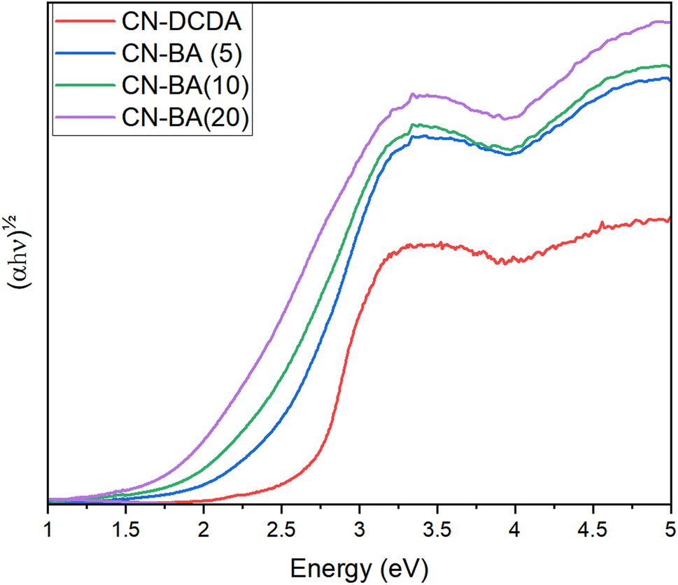 | ||
| Fig. 3 Indirect Tauc plot for CN-DCDA, CN-BA(5), CN-BA(10) and CN-BA(20). | ||
In order to test if the improved light harvesting of the CN-BA series translated into improved photocatalytic activity the materials were tested for H2 evolution. We have studied the as-prepared (labelled here bulk) samples in the presence of ∼1 wt% Pt co-catalyst (deposited in situ) and a 10 mM EDTA hole scavenger. As the synthesis method gives relatively low surface area materials (see below), we have also prepared thermally exfoliated high surface area (HSA) materials from the bulk samples for photocatalytic testing. Full details of the exfoliation process can be found in the ESI† and these show the same structural properties as the parent bulk materials. From Fig. 4 it can be seen that the highest performing material for photocatalytic hydrogen evolution was CN-BA(5) for both the bulk and HSA materials, with a large increase in activity post-thermal exfoliation. In line with past reports,3,4,52–60 the addition of BA into the carbon nitride synthesis leads to an improvement in photocatalytic hydrogen evolution rate, despite a large decrease in BET surface area. The surface area decreases with BA addition (12.8 (CN-DCDA) to 4.4 m2 g−1 (CN-BA(20)), Fig. S1, Table S2† and 192.5 m2 g−1 (HSA-CN-DCDA) to 63.8 m2 g−1 (HSA-CN-BA(20)), Fig. S10, Table S13†). However, there is not a simple correlation between the light harvesting properties of the material or surface area with photocatalytic activity.
 | ||
| Fig. 4 Rate of H2 evolved in μmol per gram of photocatalyst per hour for 2 mg of photocatalyst in 2 mL 10 mM EDTA with 1 μL H2PtCl6 (8 wt% solution) over 4 hours visible light irradiation at ∼100 mW cm−2 in a glass vial. | ||
We have also evaluated the photocatalytic CO2 reduction activity of the carbon nitride materials when modified with a FeTCPP co-catalyst in aqueous solutions. High surface area (HSA-CN) materials were soaked in solutions of the FeTCPP catalyst for 24 hours prior to washing to remove unbound catalysts, details can be found in the ESI.† Loading levels of the FeTCPP on each carbon nitride were determined via ICP and by comparison of the soaking solutions pre- and post-soaking via UV-vis (Fig. S11 and Table S15†). With the exception of FeTCPP/HSA-CN-BA(20), all of the FeTCPP/HSA-CN samples were found to reduce CO2 to CO under UV-vis illumination (>375 nm) in the presence of TEOA as a hole scavenger over 4 hours of illumination at significant levels, Fig. 5 and Table 1. Control experiments under N2 showed no significant levels of CO evolution, instead H2 becomes the dominant product (Table S17 and S18, Fig. S12†) and experiments using isotopically labelled 13CO2 show that 13CO is formed (Fig. S13†) confirming that CO is produced from the purged CO2. The CO generated while purging with N2 is due to decomposition of the TEOA hole-scavenger as discussed in the ESI page S22.† The highest rate of CO evolution was obtained by HSA-CN-BA(5)/FeTCPP, with a rate of 5.7 nmol h−1 (75 μmol g−1(FeTCPP) h−1), which although lower than results reported by others in non-aqueous solvents and higher incident light intensity (6.52 mmol g−1 with 98% CO selectivity),20,21 represents a relatively rare example of selective CO2 reduction using a hybrid molecular catalyst-carbon nitride photocatalyst in water, with the molecular catalyst enabling selectivities of greater than 2:1 (CO:H2). The rate of CO production followed a similar trend to that observed for H2 evolution using a Pt co-catalyst, with HSA-CN-BA(5)/FeTCPP out performing both HSA-CN-BA(10)/FeTCPP and HSA-CN-BA(20)/FeTCPP, however it is notable that despite having significantly worse light harvesting properties HSA-CN-DCDA achieves a higher CO evolution rate than both HSA-CN-BA(10)/FeTCPP and HSA-CN-BA(20)/FeTCPP.
 | ||
| Fig. 5 Rate of CO evolution in nmol per hour for 4 mg photocatalyst in 4 mL 10% TEOA (v/v) in water. Samples were placed under UV-vis illumination at ∼100 mW cm−2 in a quartz cuvette, for 4 hours. The Xe lamp was equipped with a water filter and a 375 nm long pass filter. Conditions were varied to confirm CO2 reduction by purging with different gases, CO2 (A) and N2 (B), using CN photocatalyst with FeTCPP in solution with no prior soaking (C), the CN photocatalyst by itself (D), just he FeTCPP in solution with no photocatalyst present (E) and the hole scavenger in aqueous solution with no catalysts present. (F) Full conditions of experiments can be found in Table S16.† | ||
| HSA-sample | Rate of evolution (μmol g−1(FeTCPP) h−1) | Selectivity (%) | ||
|---|---|---|---|---|
| CO | H2 | CO | H2 | |
| CN-DCDA | 37.567 | 17.914 | 67.71 | 32.29 |
| CN-BA(5) | 74.952 | 34.227 | 68.65 | 31.35 |
| CN-BA(10) | 47.164 | 26.037 | 64.43 | 35.57 |
| CN-BA(20) | 6.253 | 23.537 | 20.99 | 79.01 |
To assess the role of the molecular catalyst, a number of control experiments were performed. In the absence of the FeTCPP catalyst, negligible CO is evolved (Fig. 5) and H2 is the sole product (Fig. S12†). FeTCPP is able to absorb visible light, but we found that in the absence of the carbon nitride catalyst, the CO yield decreases by a factor of ca. 67 compared to the HSA-CN-BA(5)-FeTCPP sample (Table S17†) indicating that the primary photocatalytic pathway for CO formation is photon absorption by the carbon nitride with electron transfer to the iron porphyrin catalyst. Supporting this conclusion is the wavelength dependence of CO evolution for HSA-CN-DCDA-FeTCPP which matches well with the recorded UV-vis spectra of the carbon nitride, confirming that CO reduction was initiated by excitation of the carbon nitride, Fig. 6. When the FeTCPP is not attached to the carbon nitride surface, but instead is added into the aqueous solution (25 μM) the rate of CO evolution decreases by a factor of ca. 25 (HSA-CN-BA(5), Table S17†) demonstrating that attachment of the catalyst to the carbon nitride absorber is critical for efficient electron transfer to occur.61–63
 | ||
| Fig. 6 UV-vis diffuse reflectance spectra (Kubelka–Munk) of HSA-CN-DCDA pre- and post- soaking in FeTCPP solution and UV-vis spectra of 90 μM FeTCPP ethanolic solution overlaid with rate of CO evolution in μmol per gram of FeTCPP per hour for 2 mg photocatalyst in 2 mL 10% TEOA (v/v) in water. The blue arrows indicate the applicable y-axis. Samples were purged with CO2 and placed under monochromatic illumination (365, 395 and 420 nm) at 0.16 mW cm−2 in a quartz-cuvette, for 24 hours on a 150 W Xe lamp with monochromator. | ||
To understand the trends in photocatalytic activity with BA doping, we have carried out a detailed study of the electronic structure and the kinetics of the photogenerated charges. Past studies have proposed that excessive BA doping can cause the formation of high concentrations of defect sites which act as recombination centers.3 Steady-state photoluminescence data presented in this work shows that the emission peak maxima is red shifted, which is consistent with the decrease in band gap, Fig. S9.† There also appears to be a slight decrease in the intensity of the emission as the barbituric acid content is increased which could indicate a decrease in radiative recombination, in-line with a higher concentration of defects which can act as trap sites.46,64–68 Time correlated single photon counting (TCSPC) (Fig. 7, Table S11†) shows that addition of barbituric acid clearly increases the photoluminescence lifetime from ca. 3 ns (DCDA, amplitude average weighted lifetime) to ca. 5 ns (CN-BA(5)) and for all BA concentrations the lifetime exceeds that of the undoped DCDA (Fig. 7a). A similar trend is also observed for the high surface area sample (Table S12†). Longer excited state lifetimes may increase the probability of charge transfer to a catalyst, and it is reasonable to conclude that the increase in TCSPC lifetimes of BA doped CN samples contributes to the increased rate of photocatalytic hydrogen evolution and CO evolution. The steady state photoluminescence yield continues to decrease as BA levels are increased to >5% (Fig. S9†), however interestingly fitting of the TCPSC data indicates that between 5 and 20% BA there is minimal change in photoluminescent lifetime (ca. 4.7 ns CN-BA(5) vs. ca. 4.5 ns for (CN-BA(20))).
 | ||
| Fig. 7 (a) TCPSC lifetime of CN-BA series materials (excitation 371 nm and emission 465 nm, 485 nm, 495 nm and 495 nm for CN-DCDA, CN-BA(5), CN-BA(10) and CN-BA(20), respectively). (b) Change in lifetime of the HSA-CN-BA(5) sample in the presence and absence of the FeTCPP co-catalyst. The dotted green lines are from the multi-exponential fits. | ||
To explore further if the TCSPC can be used to directly monitor the rate of electron transfer to the FeTCPP from the HSA-CN, we have measured the photoluminescence lifetime following catalyst deposition and in all cases the lifetime decreases (Table S12†). In all samples, except those with the highest BA doping (CN-BA(20)), modification with FeTCPP decreases the HSA-CN lifetime and this is clearly seen in the data for HSA-CN-BA(5), Fig. 7b. The decrease in PL lifetime when FeTCPP is present is in-line with fast electron transfer (<10 ns) to the catalyst. A simple kinetic model can be constructed where there are parallel pathways for relaxation of the emissive state, either through charge transfer to the catalyst or by emission as outlined in the ESI.† Although this is a severe over-simplification, not taking into account the potential role of non-emissive trap states in charge transfer and recombination, it does give rise to similar rate constants for electron transfer to the FeTCPP catalyst for the HSA-CN-DCDA-FeTCPP, HSA-CN-BA(5)-FeTCPP and HSA-CN-BA(10)-FeTCPP samples. Notably the 10% BA doped sample did not show a large change in TCPSC lifetime upon addition of the FeTCPP catalyst, in-line with there being minimal photocatalytic CO production.
To rationalise the photocatalytic behaviour observed and the apparent lack of electron transfer from the HSA-CN-BA(20)-FeTCPP sample it is important not only to study the impact of doping on charge carrier dynamics but also the change in thermodynamic driving force for the electron transfer steps brought about due to the shift in VB and CB positions upon doping. Through the combination of both UV-vis and XPS, the band structure of each of the materials was determined. XPS can be used to measure the valence band minimum (VBM) relative to the material's Fermi level (Fig. S8†). To be able to compare materials, the Fermi level must be determined by measuring the material's work function (WF), which can be done via XPS by measuring the secondary electron cut-off (SEC). In this work, the VBM and SEC of each material has been measured and used in combination with the optical band gap determined from UV-visible diffuse reflection spectroscopy to estimate the conduction and valence band positions. The calculated band positions of each material relative to water splitting and CO2 reduction redox potentials are depicted in Fig. 8 and are stated in Table S10.† The change in band positions for CN-DCDA and CN-BA(20) agree well with the original study on copolymerisation of DCDA with barbituric acid,44 however only a single barbituric acid content was reported and the wider trend in band structure as the barbituric acid content was changed was not reported. Here we find that addition of lower levels of barbituric acid (from CN-DCDA to CN-BA(5)) causes an upshift in the VB (of +0.41 V) with only a small change in the CB to more negative potentials (of −0.13 V), leading to a decreased band gap. This positive shift in band positions continues for the CN-BA(10) sample, with further decrease in the band gap. For CN-BA(20) both bands are shifted to more positive potentials.
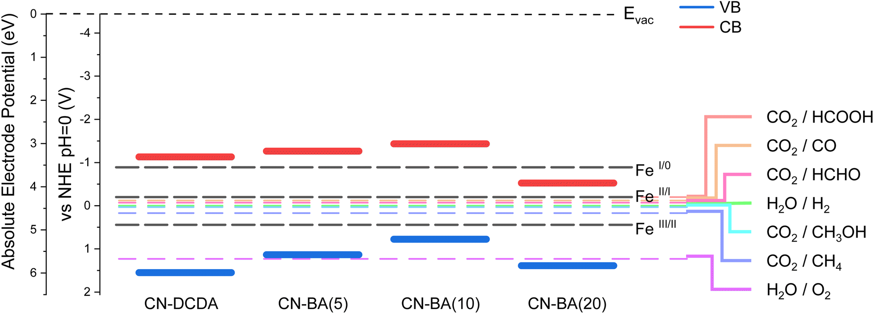 | ||
| Fig. 8 Band structures of CN-DCDA, CN-BA(5), CN-BA(10) and CN-BA(20) relative to CO2 reduction, water splitting and FeTCPP redox potentials.20 | ||
It has been previously reported that the redox couples for FeIII/II, FeII/I and FeI/0 for FeTCPP are 0.031 V, −0.61 V and −1.3 V vs. NHE, measured under Ar in dimethylformamide (DMF) and stated that FeTCPP is capable of accepting electrons from carbon nitride.20 Comparison of the band structures obtained for the bulk materials and the reported redox couples for FeTCPP in DMF can allow us to understand variations in activity (Fig. 8), although it must be taken in to consideration that the carbon nitride band structures are calculated under vacuum and the FeTCPP potentials were determined in an organic solvent, and the actual values would differ in solution and at different pH. CN-DCDA, CN-BA(5) and CN-BA(10) have CB that lie at a more negative potential than the FeI/0 redox couple, which means that electrons can transfer to the FeTCPP co-catalyst resulting in the formation of Fe0, which is required for CO2 reduction. However, CN-BA(20) has a CB which lies at a much more positive potential than the other materials and appears to lie below that of the FeI/0 redox couple. This means that the excited electron which lies in the conduction band does not have enough energy to transfer over to the FeTCPP and form the Fe0 species required, so CO2 reduction is unlikely to occur over that hybrid material, as confirmed by low CO evolution rates obtained for CN-BA(20), Fig. 5 and Table 1. We anticipate that in a complex material such as these carbon nitrides that are rich in defect states a wide variety of trap states will exist and it is reasonable to conclude that the very small amount of CO produced from CN-BA(20)-FeTCPP samples is via a low population of photoelectrons that may be trapped in higher energy states able to transfer to the co-catalyst.
Conclusions
Here we demonstrate how a carbon nitride structure prepared via co-polymerisation of DCDA and BA can be combined with a molecular catalyst to achieve selective carbon dioxide reduction to CO (75 μmol g−1(FeTCPP) h−1, 69% selectivity) in an aqueous solution. By carrying out a detailed electronic structure and photophysical study we are able to identify why a 5% BA content provides optimal activity for carbon dioxide evolution. Despite higher dopant levels giving rise to further band gap narrowing and increased light absorption there is a decrease in photocatalytic activity. Structural characterization shows an increased concentration in defect states and time-resolved photoluminescence shows that although incorporation of a low level of BA is advantageous for increasing lifetime the higher BA contents have no further positive effects. Most importantly at the highest BA concentrations, there is a substantial positive shift in the CB edge which leads to there being insufficient driving force for electron transfer to the FeTCPP co-catalyst. This work therefore connects to previous studies that have shown that low levels of BA doping can also enhance photocatalytic activity for hydrogen production,3,4,52–60,69–75 and also provides a rationale for the similar trends in activity seen there, highlighting the importance of consideration of driving force for photoelectron transfer in these systems and as the community moves towards systems without sacrificial electron donors,76 the driving force for hole transfer during water oxidation.Data availability
Underlying data collected as part of this work is available via the University of Liverpool data repository at https://doi.org/10.17638/datacat.liverpool.ac.uk%2F2204.Conflicts of interest
There are no conflicts of interest to declare.Acknowledgements
This work was supported by UKRI-EPSRC (EP/N010531/1). A. P. thanks the EPSRC for a partially funded PhD studentship under the scheme of the National Productivity Investment Fund (EP/R51231X/1). We also thank the UK Central Laser Facility for use of the FT-Raman spectrometer. XPS surface states and band structure determination for the CN-BA series of materials were performed at Stephenson Institute for Renewable Energy at the University of Liverpool, with help from members of Prof. Vinod Dhanak's group; Dr Holly Edwards, Dr Jose Coca-Clemente, Dr Huw Shiel, Dr Leanne Jones, and Dr Hatem Amli and at the EPSRC National Facility for XPS (“HarwellXPS”), operated by Cardiff University and UCL, under contract no. PR16195.References
- J. Hong, X. Xia, Y. Wang and R. Xu, J. Mater. Chem., 2012, 22, 15006–15012 RSC.
- Y. Wang, X. Wang and M. Antonietti, Angew. Chem., Int. Ed., 2012, 51, 68–89 CrossRef CAS.
- J. Zhang, X. Chen, K. Takanabe, K. Maeda, K. Domen, J. D. Epping, X. Fu, M. Antonietti and X. Wang, Angew. Chem., Int. Ed., 2010, 49, 441–444 CrossRef CAS PubMed.
- M. Shalom, M. Guttentag, C. Fettkenhauer, S. Inal, D. Neher, A. Llobet and M. Antonietti, Chem. Mater., 2014, 26, 5812–5818 CrossRef CAS.
- F. Zhang, J. Li, H. Wang, Y. Li, Y. Liu, Q. Qian, X. Jin, X. Wang, J. Zhang and G. Zhang, Appl. Catal., B, 2020, 269, 118772 CrossRef CAS.
- H. Wang, J. Zhang, X. Jin, X. Wang, F. Zhang, J. Xue, Y. Li, J. Li and G. Zhang, J. Mater. Chem. A, 2021, 9, 7143–7149 RSC.
- F. Zhang, J. Zhang, J. Li, X. Jin, Y. Li, M. Wu, X. Kang, T. Hu, X. Wang, W. Ren and G. Zhang, J. Mater. Chem. A, 2019, 7, 6939–6945 RSC.
- N. Zhang, L. Wen, J. Yan and Y. Liu, Chem. Pap., 2020, 74, 389–406 CrossRef CAS.
- Y. Li, T. Kong and S. Shen, Small, 2019, 15, 1900772 CrossRef PubMed.
- W.-J. Ong, L.-L. Tan, Y. H. Ng, S.-T. Yong and S.-P. Chai, Chem. Rev., 2016, 116, 7159–7329 CrossRef CAS.
- R. Kuriki and K. Maeda, Phys. Chem. Chem. Phys., 2017, 19, 4938–4950 RSC.
- S. Chen, J. Wei, X. Ren, K. Song, J. Sun, F. Bai and S. Tian, Molecules, 2023, 28, 4283 CrossRef CAS.
- K. Maeda, K. Sekizawa and O. Ishitani, Chem. Commun., 2013, 49, 10127 RSC.
- J. Fang, H. Fan, M. Li and C. Long, J. Mater. Chem. A, 2015, 3, 13819 RSC.
- K. Maeda, D. An, R. Kuriki, D. Lu and O. Ishitani, Beilstein J. Org. Chem., 2018, 14, 1806–1812 CrossRef CAS.
- J. J. Walsh, C. Jiang, J. Tang and A. J. Cowan, Phys. Chem. Chem. Phys., 2016, 18, 24825–24829 RSC.
- X. Ma, C. Hu and Z. Bian, Inorg. Chem. Commun., 2020, 117, 107951 CrossRef CAS.
- G. Zhao, H. Pang, G. Liu, P. Li, H. Liu, H. Zhang, L. Shi and J. Ye, Appl. Catal., B, 2017, 200, 141–149 CrossRef CAS.
- P. Huang, S. A. Pantovich, N. O. Okolie, N. A. Deskins and G. Li, ChemPhotoChem, 2020, 4, 420–426 CrossRef CAS.
- L. Lin, C. Hou, X. Zhang, Y. Wang, Y. Chen and T. He, Appl. Catal., B, 2018, 221, 312–319 CrossRef CAS.
- X. Zhang, L. Lin, D. Qu, J. Yang, Y. Weng, Z. Wang, Z. Sun, Y. Chen and T. He, Appl. Catal., B, 2020, 265, 118595 CrossRef CAS.
- R. Bonetto, F. Crisanti and A. Sartorel, ACS Omega, 2020, 5, 21309–21319 CrossRef CAS PubMed.
- S. Li, Y. Guo, L. Liu, J. Wang, L. Zhang, W. Shi, M. Aleksandrzak, X. Chen and J. Liu, Catalysts, 2023, 13, 732 CrossRef CAS.
- A. Thomas, A. Fischer, F. Goettmann, M. Antonietti, J.-O. Müller, R. Schlögl and J. M. Carlsson, J. Mater. Chem., 2008, 18, 4893 RSC.
- Y. Zheng, L. Lin, X. Ye, F. Guo and X. Wang, Angew. Chem., Int. Ed., 2014, 53, 11926–11930 CrossRef CAS PubMed.
- M. Groenewolt and M. Antonietti, Adv. Mater., 2005, 17, 1789–1792 CrossRef CAS.
- B. V. Lotsch, M. Döblinger, J. Sehnert, L. Seyfarth, J. Senker, O. Oeckler and W. Schnick, Chem.–Eur. J., 2007, 13, 4969–4980 CrossRef CAS.
- W. Tu, Y. Xu, J. Wang, B. Zhang, T. Zhou, S. Yin, S. Wu, C. Li, Y. Huang, Y. Zhou, Z. Zou, J. Robertson, M. Kraft and R. Xu, ACS Sustainable Chem. Eng., 2017, 5, 7260–7268 CrossRef CAS.
- H. Wang, Z. Sun, Q. Li, Q. Tang and Z. Wu, J. CO2 Util., 2016, 14, 143–151 CrossRef CAS.
- E. Wirnhier, M. Döblinger, D. Gunzelmann, J. Senker, B. V. Lotsch and W. Schnick, Chem.–Eur. J., 2011, 17, 3213–3221 CrossRef CAS PubMed.
- F. Goettmann, A. Fischer, M. Antonietti and A. Thomas, Angew. Chem., Int. Ed., 2006, 45, 4467–4471 CrossRef CAS PubMed.
- X. Wang, X. Chen, A. Thomas, X. Fu and M. Antonietti, Adv. Mater., 2009, 21, 1609–1612 CrossRef CAS.
- Y. Zhang, H. Gong, G. Li, H. Zeng, L. Zhong, K. Liu, H. Cao and H. Yan, Int. J. Hydrogen Energy, 2017, 42, 143–151 CrossRef CAS.
- Y. Zheng, J. Liu, J. Liang, M. Jaroniec and S. Z. Qiao, Energy Environ. Sci., 2012, 5, 6717 RSC.
- J. Zhang, M. Zhang, R.-Q. Sun and X. Wang, Angew. Chem., Int. Ed., 2012, 51, 10145–10149 CrossRef CAS.
- Y. Wang, J. Hong, W. Zhang and R. Xu, Catal. Sci. Technol., 2013, 3, 1703 RSC.
- J. Zhang, X. Chen, K. Takanabe, K. Maeda, K. Domen, J. D. Epping, X. Fu, M. Antonietti and X. Wang, Angew. Chem., Int. Ed., 2010, 49, 441 CrossRef CAS PubMed.
- G. Socrates, Infrared and Raman Characteristic Group Frequencies. Tables and Charts, John Wiley & Sons Ltd, Chichester, 3rd edn, 2001 Search PubMed.
- P. Larkin, Infrared and Raman Spectroscopy, Elsevier, Cambridge, MA, 2nd edn, 2018 Search PubMed.
- J. Li, B. Shen, Z. Hong, B. Lin, B. Gao and Y. Chen, Chem. Commun., 2012, 48, 12017 RSC.
- S. W. Cao, Y. P. Yuan, J. Fang, M. M. Shahjamali, F. Y. C. Boey, J. Barber, S. C. Joachim Loo and C. Xue, Int. J. Hydrogen Energy, 2013, 38, 1258–1266 CrossRef CAS.
- X. Kang, Y. Kang, X. Hong, Z. Sun, C. Zhen, C. Hu, G. Liu and H. Cheng, Prog. Nat. Sci.: Mater. Int., 2018, 28, 183 CrossRef CAS.
- Y. Wang, J. Hong, W. Zhang and R. Xu, Catal. Sci. Technol., 2013, 3, 1703 RSC.
- J. Zhang, X. Chen, K. Takanabe, K. Maeda, K. Domen, J. D. Epping, X. Fu, M. Antonietti and X. Wang, Angew. Chem., Int. Ed., 2010, 49, 441–444 CrossRef CAS PubMed.
- V. W. Lau, I. Moudrakovski, T. Botari, S. Weinberger, M. B. Mesch, V. Duppel, J. Senker, V. Blum and B. V Lotsch, Nat. Commun., 2016, 7, 12165 CrossRef CAS PubMed.
- J. Qin, S. Wang, H. Ren, Y. Hou and X. Wang, Appl. Catal., B, 2015, 179, 1–8 CrossRef CAS.
- L. Li, Q. Meng, H. Lv, L. Shui, Y. Zhang, Z. Zhang, Z. Chen, M. Yuan, R. Nötzel, X. Wang, J.-M. Liu and G. Zhou, Appl. Surf. Sci., 2018, 428, 739–747 CrossRef CAS.
- E. Vorobyeva, Z. Chen, S. Mitchell, R. K. Leary, P. Midgley, J. M. Thomas, R. Hauert, E. Fako, N. López and J. Pérez-Ramírez, J. Mater. Chem. A, 2017, 5, 16393–16403 RSC.
- M. Li, S. Zhang, X. Liu, J. Han, X. Zhu, Q. Ge and H. Wang, Eur. J. Inorg. Chem., 2019, 2019, 2058–2064 CrossRef CAS.
- T. S. Miller, A. B. Jorge, T. M. Suter, A. Sella, F. Corà and P. F. McMillan, Phys. Chem. Chem. Phys., 2017, 19, 15613–15638 RSC.
- X. Wang, K. Maeda, A. Thomas, K. Takanabe, G. Xin, J. M. Carlsson, K. Domen and M. Antonietti, Nat. Mater., 2009, 8, 76–80 CrossRef CAS PubMed.
- J. Qin, S. Wang, H. Ren, Y. Hou and X. Wang, Appl. Catal., B, 2015, 179, 1–8 CrossRef CAS.
- X. Wei, H. Jiang and Z. Liu, RSC Adv., 2016, 6, 81372–81377 RSC.
- L. Chen, Z. Song, X. Liu, L. Guo, M. Li and F. Fu, Analyst, 2018, 143, 1609–1614 RSC.
- L. Li, Q. Meng, H. Lv, L. Shui, Y. Zhang, Z. Zhang, Z. Chen, M. Yuan, R. Nötzel, X. Wang, J.-M. Liu and G. Zhou, Appl. Surf. Sci., 2018, 428, 739–747 CrossRef CAS.
- C. Tsounis, R. Kuriki, K. Shibata, J. J. M. Vequizo, D. Lu, A. Yamakata, O. Ishitani, R. Amal and K. Maeda, ACS Sustainable Chem. Eng., 2018, 6, 15333–15340 CrossRef CAS.
- C. Zhou, C. Lai, P. Xu, G. Zeng, D. Huang, Z. Li, C. Zhang, M. Cheng, L. Hu, J. Wan, F. Chen, W. Xiong and R. Deng, ACS Sustainable Chem. Eng., 2018, 6, 6941–6949 CrossRef CAS.
- G. Li, Q. Wang, Y. Wu, Y. Li and L. Guo, Spectrochim. Acta, Part A, 2019, 215, 307–312 CrossRef CAS PubMed.
- W. Tang, Y. Tian, B. Chen, Y. Xu, B. Li, X. Jing, J. Zhang and S. Xu, ACS Appl. Mater. Interfaces, 2020, 12, 6396–6406 CrossRef CAS.
- Z. Teng, W. Cai, S. Liu, C. Wang, Q. Zhang, S. Chenliang and T. Ohno, Appl. Catal., B, 2020, 271, 118917 CrossRef CAS.
- R. Kuriki, K. Sekizawa, O. Ishitani and K. Maeda, Angew. Chem., Int. Ed., 2015, 54, 2406–2409 CrossRef CAS PubMed.
- B. Ma, G. Chen, C. Fave, L. Chen, R. Kuriki, K. Maeda, O. Ishitani, T. C. Lau, J. Bonin and M. Robert, J. Am. Chem. Soc., 2020, 142, 6188–6195 CrossRef CAS.
- R. Kuriki, O. Ishitani and K. Maeda, ACS Appl. Mater. Interfaces, 2016, 8, 6011–6018 CrossRef CAS PubMed.
- G. Zhang, M. Zhang, X. Ye, X. Qiu, S. Lin and X. Wang, Adv. Mater., 2014, 26, 805–809 CrossRef CAS PubMed.
- S. Bai, X. Wang, C. Hu, M. Xie, J. Jiang and Y. Xiong, Chem. Commun., 2014, 50, 6094–6097 RSC.
- S. Zhou, Y. Liu, J. Li, Y. Wang, G. Jiang, Z. Zhao, D. Wang, A. Duan, J. Liu and Y. Wei, Appl. Catal., B, 2014, 158–159, 20–29 CrossRef CAS.
- J. Zhang, M. Zhang, R.-Q. Sun and X. Wang, Angew. Chem., Int. Ed., 2012, 51, 10145–10149 CrossRef CAS PubMed.
- J. Yu, K. Wang, W. Xiao and B. Cheng, Phys. Chem. Chem. Phys., 2014, 16, 11492 RSC.
- E. Vorobyeva, Z. Chen, S. Mitchell, R. K. Leary, P. Midgley, J. M. Thomas, R. Hauert, E. Fako, N. López and J. Pérez-Ramírez, J. Mater. Chem. A, 2017, 5, 16393–16403 RSC.
- J. Ren, Y. Wu, Y. Dai, D. Sha, J. Pan, M. Chen, J. Wang, Q. Wang, N. Ye and X. Yan, J. Mater. Sci.: Mater. Electron., 2017, 28, 641–651 CrossRef CAS.
- M. Ning, Z. Chen, L. Li, Q. Meng, Z. Chen, Y. Zhang, M. Jin, Z. Zhang, M. Yuan, X. Wang and G. Zhou, Electrochem. Commun., 2018, 87, 13–17 CrossRef CAS.
- J. Barrio, L. Lin, X. Wang and M. Shalom, ACS Sustainable Chem. Eng., 2018, 6, 519–530 CrossRef CAS.
- C. Zhou, C. Lai, D. Huang, G. Zeng, C. Zhang, M. Cheng, L. Hu, J. Wan, W. Xiong, M. Wen, X. Wen and L. Qin, Appl. Catal., B, 2018, 220, 202–210 CrossRef CAS.
- M. Li, S. Zhang, X. Liu, J. Han, X. Zhu, Q. Ge and H. Wang, Eur. J. Inorg. Chem., 2019, 2019, 2058–2064 CrossRef CAS.
- J. Li, D. Wu, J. Iocozzia, H. Du, X. Liu, Y. Yuan, W. Zhou, Z. Li, Z. Xue and Z. Lin, Angew. Chem., Int. Ed., 2019, 58, 1985–1989 CrossRef CAS PubMed.
- R. Zeng, K. Lian, B. Su, L. Lu, J. Lin, D. Tang, S. Lin and X. Wang, Angew. Chem., Int. Ed., 2021, 60, 25055–25062 CrossRef CAS PubMed.
Footnote |
| † Electronic supplementary information (ESI) available. See DOI: https://doi.org/10.1039/d3ta02872k |
| This journal is © The Royal Society of Chemistry 2023 |