
Porous bipolar polymers as organic cathodes for sustainable sodium/potassium-ion batteries†
Motahareh
Mohammadiroudbari
 a,
Jinghao
Huang
a,
Eric Youngsam
Kim
a,
Zhenzhen
Yang
b,
Fu
Chen
c and
Chao
Luo
*ad
a,
Jinghao
Huang
a,
Eric Youngsam
Kim
a,
Zhenzhen
Yang
b,
Fu
Chen
c and
Chao
Luo
*ad
aDepartment of Chemistry and Biochemistry, George Mason University, Fairfax, VA 22030, USA
bMaterials Science Division, Argonne National Laboratory, Lemont, IL 60439, USA
cDepartment of Chemistry and Biochemistry, University of Maryland, College Park, MD 20742, USA
dQuantum Science & Engineering Center, George Mason University, Fairfax, VA 22030, USA. E-mail: cluo@gmu.edu
First published on 10th July 2023
Abstract
Redox-active porous polymers are becoming promising organic electrode materials for alkali-ion batteries because of their tunable pore size, flexible chemical structure, and high thermal stability. This work presents various porous bipolar polymers as cathodes in Na-ion batteries (NIBs) and K-ion batteries (KIBs). Two structural units containing carbonyl and amine active centers, respectively, were introduced into the repeating units of the polymers by the polycondensation of N,N,N′,N′-tetrakis(4-aminophenyl)-1,4-phenylenediamine (TAP) and various dianhydrides. The resulting bipolar polymers undergo multi-electron redox reactions involving both cations and anions during battery charge and discharge. The impacts of extended conjugation structures and porosity on the electrochemical performances were investigated by tuning the conjugation structures in the dianhydride monomers. The bipolar polymers with extended conjugation structures and small pore size exhibit superior electrochemical performance in NIBs and KIBs in terms of high redox potentials, long cycle life, and fast-charging capability, demonstrating great promise as organic cathode materials for alkali-ion batteries.
Introduction
The fast-paced development of energy storage devices and the urge to achieve net-zero carbon emissions attract considerable efforts to improve sustainability and electrochemical performances of state-of-the-art Li-ion batteries (LIBs).1,2 In addition, energy sources are also rapidly transitioning from fossil fuels toward renewable energies, stimulating the demand for large-scale sustainable energy storage systems.3,4 However, the limited availability and uneven distribution of lithium resources in the earth's crust cannot satisfy these needs, motivating an extensive search for low-cost and abundant alternatives with comparable electrochemical behaviors. To this end, Na-ion batteries (NIBs) and K-ion batteries (KIBs) with similar redox mechanisms are promising alternatives to LIBs.5–7To achieve sustainable NIBs and KIBs, inorganic cathode materials composed of heavy transition metals such as cobalt, nickel, etc. should be replaced by cost-effective and abundant materials.8,9 Organic electrode materials (OEMs) with the advantages of low cost, lightweight, abundance, recyclability, environmental benignity, high sustainability, and flexible structural tunability offer numerous opportunities to develop high-performance alkali-ion batteries.10–12 The highly tunable organic/polymer synthetic pathways allow adding multiple different redox-active centers into chemical structures to enhance electrochemical performances of OEMs.13,14 However, small organic molecules as active materials suffer from low electronic/ionic conductivity, high solubility in electrolytes, and structural changes after cycling. Among different approaches to improving the performance of small organic molecules, polymerization stands out due to high stability and low solubility of high-molecular-weight polymers.15–17 Redox-active polymers can host multiple functional groups and extended conjugation structures in their repeating units to increase the specific capacity and conductivity.18 More importantly, long chains of polymers resist dissolution in the organic electrolytes before and after cycling.19 Redox-active polymers feature characteristics such as fast reaction kinetics, long cycle life, and high thermal stability.20
To date, polymers with carbonyl functional groups as their redox-active sites have been extensively studied due to their high stability, abundant structural diversity, and fast reaction kinetics.21–23 In particular, polyimides with high thermal/chemical stability are promising candidates for high-performance cathode materials in alkali-ion batteries.24,25 However, redox potentials of polyimides (2–2.5 V versus Na/Na+) are low compared to inorganic counterparts (>3 V versus Na/Na+).26 To enhance the redox potential of organic cathodes, amine groups based on anion insertion mechanisms are introduced into OEMs to deliver high redox potentials above 3 V versus Na/Na+, but they suffer from low specific capacity (<100 mA h g−1). To achieve high-voltage and high-capacity organic cathodes, the combination of n-type carbonyl groups and p-type amine groups in the repeating unit of the polymers offers opportunities.27–31 Furthermore, extended conjugation structures in the repeating units of polymers are crucial to facilitate ion/electron transfer along the chains.32 To further improve electrochemical performances, propagating the polymer chains in more than one direction to form two-dimensional and three-dimensional porous polymers has been considered as an optimal structure design strategy.33–38 Currently, covalent organic frameworks (COFs),39–42 hyper crosslinked polymers (HCPs), covalent triazine frameworks (CTFs),43 porous aromatic frameworks (PAFs), and conjugated porous polymers (CPPs) are the main categories of porous organic polymers.44,45 Among them, porous polymers with conjugated aromatic rings along the two-dimensional network feature unique properties of fast electron transfer and high conductivity.
In this work, we designed and synthesized a class of mesoporous polymers with the same diamine moiety yet different dianhydride moieties in repeating units to be used as cathode materials in NIBs and KIBs. To study the effect of extended conjugation structures on electron transfer during redox reactions, four dianhydrides listed as pyromellitic dianhydride (PMDA), 4,4′-biphthalic anhydride (BPDA), naphthalenetetracarboxylic dianhydride (NTCDA), and perylenetetracarboxylic dianhydride (PTCDA) were selected. Polycondensation reactions of N,N,N′,N′-tetrakis(4-aminophenyl)-1,4-phenylenediamine (TAP) and these dianhydrides afford four mesoporous polymers named as PPM, PBP, PNT, and PPT in Scheme 1a. The presence of carbonyl groups and amine groups with mesoporous structures in the polymers enabled the insertion/extraction of multiple ions and electrons. Possessing the properties of both n-type and p-type OEMs, these polymers can uptake both cations and anions. The proposed multi-electron redox reaction mechanism is displayed in Scheme 1b. Carbonyl groups reversibly react with Na+/K+, while amine groups reversibly react with PF6−, accompanied by intramolecular electron transfer in conjugation structures during redox reactions. Among the four polymers, PNT and PPT with large delocalized π conjugated structures and mesopores show exceptional electrochemical performances in NIBs and KIBs, in terms of high redox potentials, high capacity, long lifetime, and fast-charging capability. To further elevate the conductivity and stability of PNT and PPT cathodes, single-layer graphene was used in the composition of cathodes. The π–π stacking between highly conductive graphene layers and bipolar porous polymers can boost ion/electron transfer, accommodate the large volume change caused by ion insertion/extraction, and minimize the dissolution of the polymers/reaction intermediates/products upon cycling, improving the performance of polymer cathodes. The results demonstrate that designing bipolar porous polymers with extended conjugation structures is a promising strategy for obtaining high-performance polymer cathodes in NIBs and KIBs.
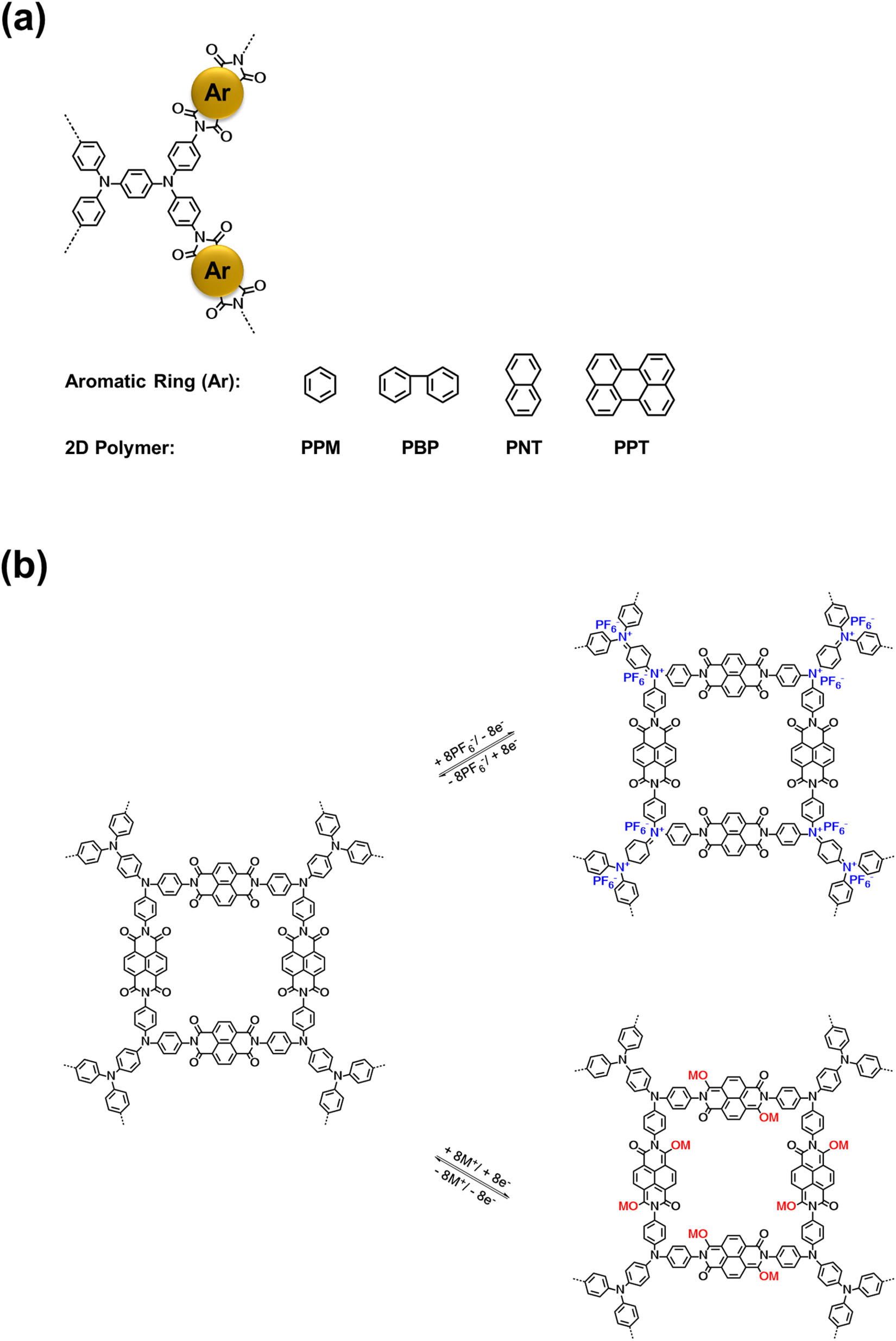 | ||
| Scheme 1 Structures and reaction mechanism: (a) the molecular structure of four conjugated mesoporous polymers; (b) the proposed reaction mechanism for PNT as an example, where M represents Na/K ion. | ||
Results and discussion
Four bipolar porous polymers in Scheme 1a were synthesized by condensation polymerization under the N2 gas following a previously reported procedure.46,47 Several characterization techniques such as X-ray diffraction (XRD), solid-state nuclear magnetic resonance (NMR), Fourier-transform infrared spectroscopy (FTIR), scanning electron microscopy (SEM), and Brunauer–Emmett–Teller (BET) measurements were employed to investigate the chemical structure, morphology, and porosity of the polymers. As shown in Fig. S1a and b,† the porous polymers did not show any sharp peaks in the XRD plots. However, a couple of small peaks around 10 and 25° were detected, corresponding to the ordered regions (Fig. S1c and d†). Since the porous polymers were insoluble in organic solvents, solid-state 13C NMR and 17O NMR were utilized to verify the molecular structure. As shown in Fig. 1a, the signal at 162.16 ppm is consistent with the carbonyl groups in PNT. The nitrogen-substituted phenyl carbons were identified by the signal at 146.63 ppm. The aromatic carbons showed a signal at 128.77 ppm. The small peaks at 63.35 and 23.94 ppm could be related to the small amount of residual solvent trapped in the pores of the polymer. PPT showed a similar peak at 162.55 ppm, corresponding to the carbonyl groups. Also, the nitrogen-substituted phenyl revealed a signal at 145.86 ppm. The aromatic carbon peaks appeared at 129.74 and 122.75 ppm for PPT (Fig. 1b). The peak around 50 ppm belongs to the spinning sidebands of aromatic carbons48,49 (128.77 ppm for PNT and 129.74/122.75 ppm for PPT). The peak representing the carbonyl group in 17O NMR was observed at 379.78 and 380.62 ppm for PNT and PPT, respectively (Fig. 1c and d). The FTIR spectra of two polymers along with their monomers are shown in Fig. 1e and f. The presence of twin characteristic peaks for TAP is related to the amine group (3300–3500 cm−1). These peaks disappeared after polymerization, indicating a successful polycondensation reaction. Symmetric and asymmetric stretching vibrations of carbonyl groups in NTCDA and PTCDA at 1580 and 1760 cm−1 shifted to lower wavenumbers after polymerization because of introducing more aromatic rings and amide ending groups in the repeating units of PNT and PPT.17,21 Introducing more aromatic rings and amide ending groups next to carbonyl groups stabilizes the π-bond and lowers the energy of carbonyl groups, resulting in a shift to lower wavenumbers. The peak around 1345 cm−1 was assigned to the C–N–C vibration.46 FTIR spectra for PPM and PBP also confirmed the successful polymerization with similar characteristic peaks (Fig. S2†). SEM images elucidated the difference in the shapes of microparticles due to the variation in the structural units. Both PNT and PPT were identified as irregularly shaped microparticles. As shown in Fig. 1g and h, SEM images of both polymers demonstrated the formation of irregularly shaped microparticles because of disorder in the alignment of long chains of polymers. Similarly, the other two polymers also showed irregular shapes (Fig. S3†). To measure the pore size of the polymers, BET measurements were carried out. N2 adsorption–desorption results are listed in Table S1.† The average values for pore sizes are between 2 and 14 nm, corresponding to mesoporous structures. Moreover, the specific molar adsorption with the relative pressure was plotted for all four polymers (Fig. S4†). The pore distribution of the mesoporous polymers is also presented in Fig. S5.†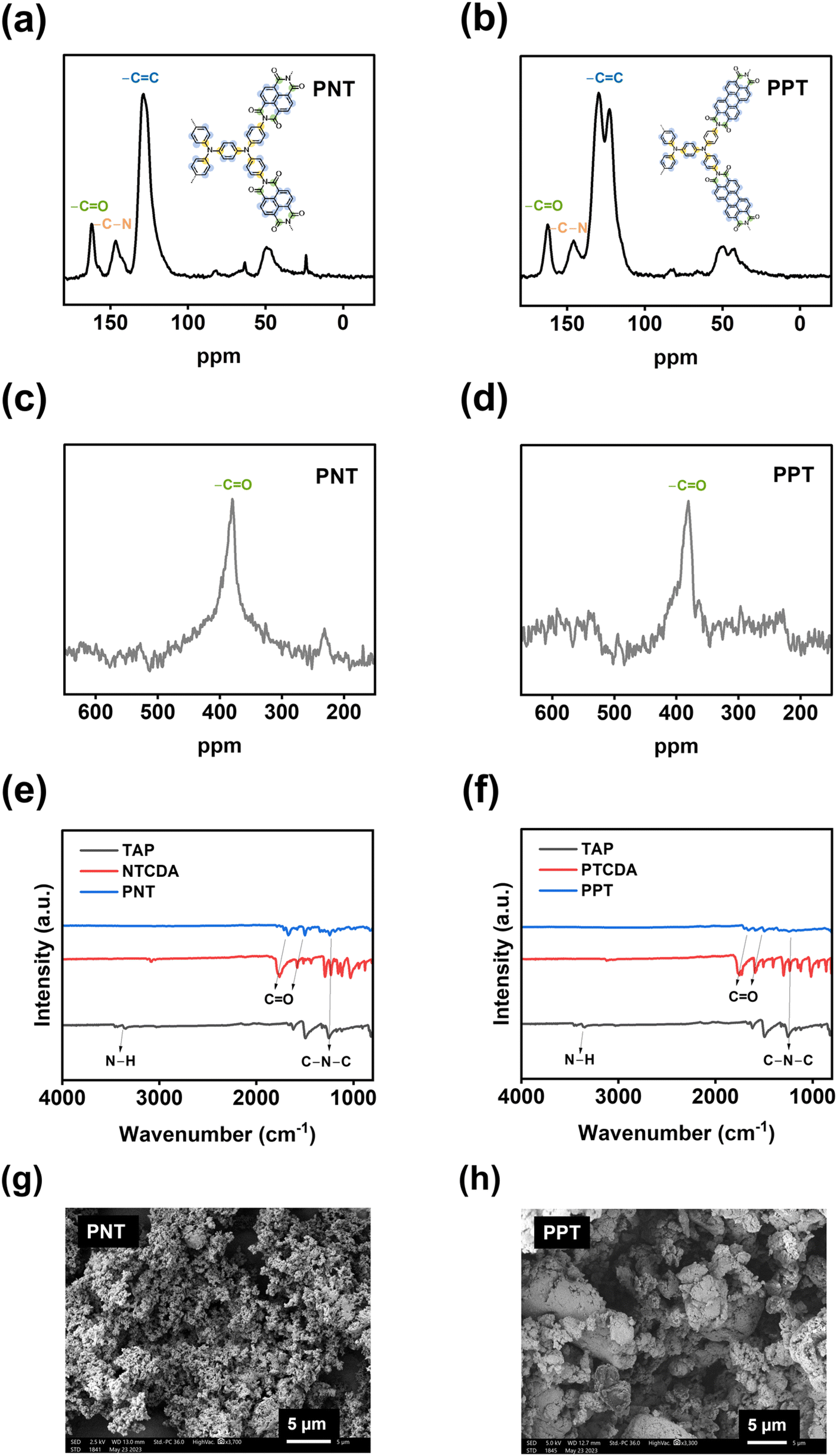 | ||
| Fig. 1 Material characterizations for PNT and PPT: (a and b) 13C solid-state NMR, (c and d) 17O solid-state NMR, (e and f) FTIR spectra, (g and h) SEM images. | ||
The electrochemical performances of PNT, PPT, PPM, and PBP in NIBs were investigated by galvanostatic charge–discharge tests. The charge–discharge curves and the cyclability of polymers were compared in the cutoff window of 1–3.8 V at the current density of 50 mA g−1. PNT with a naphthalene backbone delivered a high reversible capacity of 131.7 mA h g−1 with three pairs of sloping redox plateaus centered at 2.0 V, 2.3 V, and 3.4 V (Fig. 2a). PPT with a perylene-based building block showed similar charge–discharge behaviors with a reversible capacity of 91 mA h g−1 (Fig. 2b). As shown in Fig. 2c, both PNT and PPT delivered a very stable cycling performance for 150 cycles while maintaining a coulombic efficiency of ∼100%. In contrast, PPM and PBP showed a pair of redox plateaus at ∼3.4 V (Fig. 2d and e) for amine group-based anion insertion reaction, which is similar to that of PNT and PPT, but redox plateaus for carbonyl groups in PPM and PBP are much lower than that of PNT and PPT due to distinct conjugation structures in the four polymers. These results indicate that extended conjugation structures in PNT and PPT enhance the redox potentials of carbonyl groups. Though PPM and PBP showed an initial capacity higher than 120 mA h g−1, they suffer from fast capacity loss upon long-term cycling (Fig. 2f), demonstrating that the conjugation structure also impacts the cyclic stability. Both PNT and PPT maintained capacity retention above 80% for 150 cycles while showing a coulombic efficiency of ∼100%. In contrast, PPM and PBP lost half of their capacity in less than 20 cycles (Fig. S6†). The extended conjugation structure played a critical role in improving the redox potentials and cyclic stability of polymer cathodes.
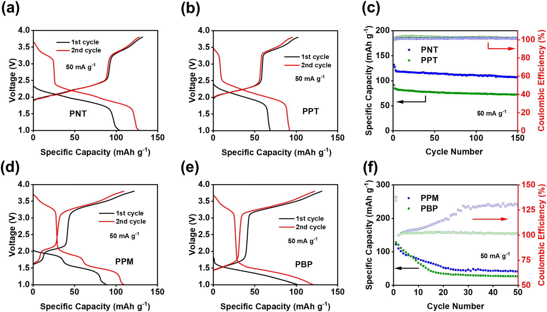 | ||
| Fig. 2 Galvanostatic charge–discharge curves in NIBs: (a) PNT, (b) PPT, (d) PPM, (e) PBP; cycling performance in NIBs: (c) PNT and PPT, (f) PPM and PBP. | ||
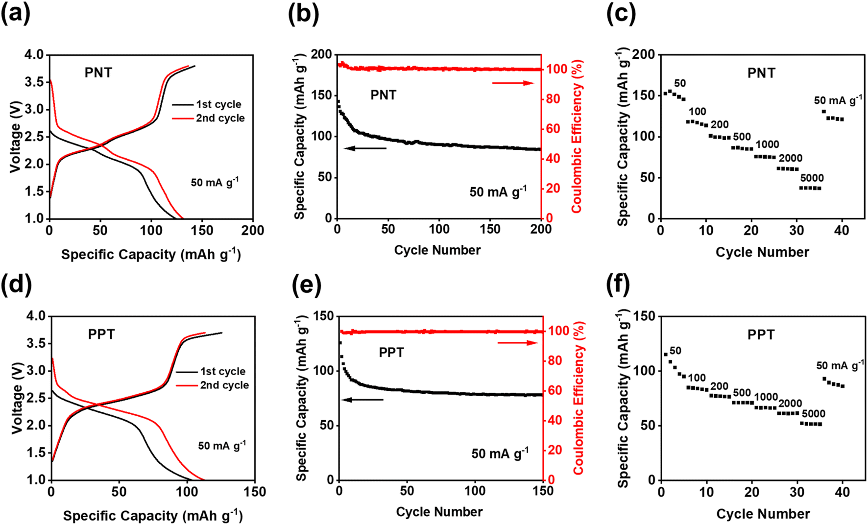
Since PNT and PPT with extended π-conjugation aromatic structures showed better performance than PPM and PBP in NIBs, further studies were focused on the cells with PNT and PPT as cathodes in NIBs. To optimize the performances of PNT and PPT, 20 wt% single-layer graphene was used to replace carbon black in the polymer cathodes. The large surface area of single-layer graphene enables better contact and strong interactions between the polymers and graphene, boosting the conductivity and stability of polymer cathodes. The charge–discharge curves for the PNT/single-layer graphene cathode at 50 mA g−1 in the cutoff window of 1–3.8 V are shown in Fig. 3a. This cathode delivered an initial charge capacity of 141.5 mA h g−1 and similar redox plateaus as that without single-layer graphene in Fig. 2a. As shown in Fig. 3b, the cell retained a capacity higher than 100 mA h g−1 with a high coulombic efficiency for 200 cycles. To further exploit reaction kinetics, cyclic voltammetry (CV) and rate capability tests were carried out. Three pairs of sharp peaks were observed in the CV plot at the scan rate of 0.1 mV s−1 (Fig. S7†). The sharp peaks centered at 1.9 V, 2.1 V, and 3.4 V correspond to the plateaus observed in the charge–discharge curves. The interaction between PF6− and amine groups in the polymers resulted in the redox peaks at 3.4 V, while reversible reactions between Na+ and carbonyl groups in the polymers led to the peaks at 1.9 V and 2.1 V. In addition, rate capability was evaluated by testing the cell at incremental current densities from 50 mA g−1 to 5000 mA g−1. The average initial capacity of 132 mA h g−1 could be fully recovered when returning to the initial current density of 50 mA g−1 (Fig. 3c). Overall, the PNT cathode demonstrated great electrochemical performance in NIBs.
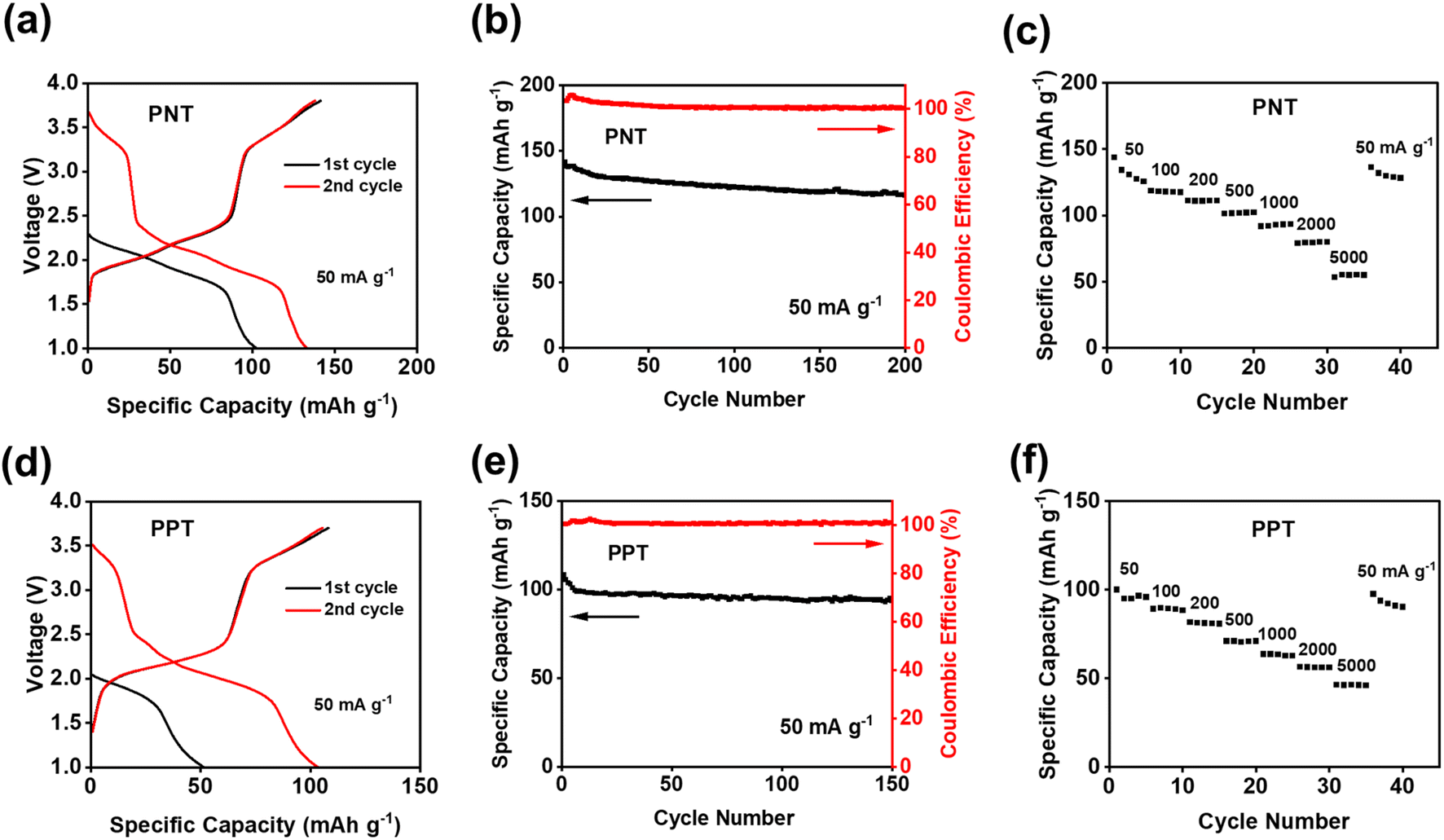 | ||
| Fig. 3 Electrochemical performance of PNT/PPT with single-layer graphene in NIBs: (a) and (d) galvanostatic charge–discharge curves; (b) and (e) cycling performance; (c) and (f) rate capability at various current densities. | ||
We also tested PPT/single-layer graphene cathodes to further understand the effect of extended conjugated rings on the electrochemical performance. The charge–discharge curves for the PPT cathode are shown in Fig. 3d, where multiple plateaus confirmed the multi-electron redox reaction. Two plateaus at ∼1.8 V and ∼2.2 V appeared during the discharge, corresponding to two broad cathodic peaks in the CV plot (Fig. S8a†). During the charge, a long and sloping plateau at ∼2.2 V was observed, corresponding to a sharp anodic peak in the CV plot. This indicated that the extraction of Na+ to restore the carbonyl groups happened at close voltages. There was also another pair of anodic and cathodic peaks at the higher voltage region around 3.4 V for the anion-insertion reaction of amine groups. The calculated b values for CV at scan rates of 0.1–1 mV s−1 confirmed fast and robust redox kinetics for PPT in NIBs (Fig. S8b†). The initial charge capacity of 108 mA h g−1 was delivered at the current density of 50 mA g−1, and it was retained for 150 cycles (Fig. 3e). To evaluate the stability of the electrodes upon cycling, charge/discharge curves for the 150th cycle have been provided. The curves for PNT and PPT in NIBs still show the initial plateaus, confirming the multi-electron redox reaction upon long-term cycling (Fig. S9†). The rate capability test showed fast reaction kinetics, where the initial capacity at 50 mA g−1 was recovered with a retention factor of 96% (Fig. 3f) after testing the cell at incremental current densities from 50 mA g−1 to 5000 mA g−1. To explore the fast-charging capability, the cell was tested at 1000 mA g−1 for up to 2000 cycles. The capacity remained remarkably stable because of the highly reversible redox reaction even at a very high current density (Fig. S10†). Though PPT showed a lower initial capacity than PNT, the cyclic stability and reaction kinetics were improved in the PPT cathodes. The larger conjugation structure stabilizes ion/electron transfer through the backbone of the polymer, yielding a reversible redox reaction for a longer lifetime.
Since PNT and PPT exhibited exceptional electrochemical performance in NIBs, they were further exploited as cathodes in KIBs. As shown in Fig. S11,† the CV plot showed two pairs of peaks centered at ∼2.15 and ∼2.45 V, corresponding to the multi-electron redox reaction in KIBs. The initial capacity of 143 mA h g−1 was delivered for the PNT cathode in KIBs (Fig. 4a). Compared to NIBs, the long-term cycling stability test exhibited faster capacity decay, especially during initial cycles (Fig. 4b). This behavior is ascribed to the higher diffusion resistance and larger volume change caused by large-size K ions. The rate capability was also tested to evaluate the kinetics of redox reactions in KIBs. As shown in Fig. 4c, the reversible capacity of 75 mA h g−1 was preserved at the current density of 1000 mA g−1, suggesting robust reaction kinetics. After returning to the initial current density of 50 mA g−1, a retention factor of 82% was observed for PNT in KIBs. The PPT cathode was also tested in KIBs to explore the universal performance in alkali-ion batteries. The CV test showed two pairs of cathodic peaks at ∼2.2 V and ∼2.4 V and anodic peaks at ∼2.5 V and 2.7 V (Fig. S12†), corresponding to the plateaus in the charge–discharge curves (Fig. 4d). The PPT cathode delivered an initial capacity of 126 mA h g−1 at the current density of 50 mA g−1. As shown in Fig. 4e, this cathode maintained a capacity higher than 75 mA h g−1 for 150 cycles with higher stability than PNT in KIBs. Although the PNT and PPT cathode in KIBs showed gradual capacity decay after 150 cycles, the charge–discharge curves still show reversible plateaus, confirming the multi-electron redox reaction upon long-term cycling (Fig. S13†). To explore the fast-charging capability, the cell with a PPT cathode was tested at 1000 mA g−1. As shown in Fig. S14,† the capacity remained above 50 mA h g−1 even after 2000 cycles with a coulombic efficiency of ∼100%. Moreover, when cycled at current densities of 50–5000 mA g−1, PPT revealed great rate capability in KIBs (Fig. 4f). The average capacity of 104 mA h g−1 was retained after recovering to the initial current density of 50 mA g−1 from 5000 mA g−1, corresponding to 85% of the initial capacity. In Fig. S15,† the summary of electrochemical performance confirms that our designed polymer features higher capacity compared to the previously reported OEMs with similar redox chemistry.50–53 These results confirm that bipolar porous polymers are promising and universal electrode materials in NIBs and KIBs.
 | ||
| Fig. 4 Electrochemical performance of PNT/PPT with single-layer graphene in KIBs: (a) and (d) galvanostatic charge–discharge curves; (b) and (e) cycling performance; (c) and (f) rate capability at various current densities. | ||
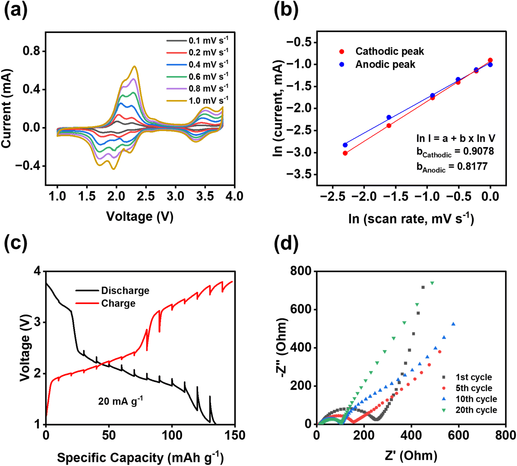
To further understand the fast reaction kinetics of bipolar porous polymers, CV at various scan rates, galvanostatic intermittent titration technique (GITT), and electrochemical impedance spectroscopy (EIS) were conducted. CV was performed at the scan rates of 0.1–1 mV s−1 (Fig. 5a) to monitor the changes in voltage and current of anodic and cathodic peaks. The potential hysteresis of anodic and cathodic peaks is elevated at higher scan rates because of larger polarization. Since there are multiple peaks at 1.5–2.5 V, peak deconvolution was performed as shown in Fig. S16 for anodic peaks and Fig. S17† for cathodic peaks. The fitted peaks 1 in Fig. S16 and S17† were used to calculate the b values for the cathodic/anodic peaks. As shown in Fig. 5b, the calculated slope values, representing the b value (I = a × vb), are equal to 0.9078 and 0.8177 for cathodic and anodic peaks, respectively. These values are close to 1.0, indicating that the pseudo-capacitive behavior is dominant in reaction kinetics. Moreover, in most regions of the GITT plot (Fig. 5c), the potential change of the cell is low (less than 110 mV) after the resting period of three hours at each fraction. The resistance related to ion transfer at the interface of the electrode and the electrolyte was measured by EIS to investigate the dynamic changes in the cells during cycling. As shown in Fig. 5d, a large depressed semi-circle representing the interfacial resistance is decreased from the first cycle to the 10th cycle and stabilized from the 10th cycle to the 20th cycle, demonstrating that the formed cathode electrolyte interphase (CEI) in the cathode is stable and robust upon cycling. The depressed semi-circle in the Nyquist plot is related to the interphasial resistances, including the CEI resistance and charge transfer resistance. The low and stable resistance from the 10th to 20th cycles demonstrates the formation of stable CEI and fast charge transfer between the electrolyte and the surface of the electrode. This is vital for the high stability and fast reaction kinetics of polymer cathodes. The results from CV, GITT, and EIS confirmed the fast reaction kinetics and low resistance of the PNT cathode in NIBs.
 | ||
| Fig. 5 Reaction kinetics of PNT with single-layer graphene in NIBs: (a) cyclic voltammograms at various scan rates; (b) the natural logarithm of peak current versus scan rate; (c) potential response during GITT measurements; (d) impedance analysis at different cycles. | ||
To further exploit the interphase and reaction mechanism for PNT in NIBs, X-ray photoelectron spectroscopy (XPS) was employed to exploit the pristine PNT cathode and cycled PNT cathodes at different discharge/charge stages. XPS is a surface technique to study the structure of the electrode surface up to 10 nm. As shown in Fig. 6, C 1s, O 1s, F 1s, and N 1s XPS spectra of the pristine cathode, the cathodes discharged to 1 V, charged to 3.8 V, and discharged to 2.6 V were compared to explore the structural evolution during different stages of the redox reaction. The charge/discharge curves have been provided in Fig. S18† to show the stages of charge/discharge for XPS analyses. For the analyses, the reference peak for the graphitic carbon was calibrated at 284.4 eV. In C 1s spectra, the intensity of the peak at 285.5 eV representing the C–O/C–N group increases after being fully discharged to 1 V.54 This indicates the reduction of carbonyl groups to C–O groups by Na ions and electrons during the discharge process. The C–O/C–N peak intensity decreases after being charged to 3.8 V, demonstrating the reversible carbonyl reaction in NIBs. In addition, carbonate-based components in the CEI layer also showed peaks at 289.6 eV in the C 1s spectra of charged/discharged electrodes. The peak at 532.5 eV in the O 1s XPS spectrum corresponds to the C![[double bond, length as m-dash]](https://www.rsc.org/images/entities/char_e001.gif) O group. The peak at 533.8 eV for the fully discharged stage represents the C–O group after sodium ions interact with carbonyl bonds. The C–O peak still presents in the fully charged stage and after being discharged back to 2.6 V, demonstrating the species in the CEI contains C–O groups. The peak at 689.8 eV in the F 1s XPS spectrum was assigned to the C–F peak, which is related to the presence of polytetrafluoroethylene (PTFE) as the binder. The peak that appeared at 684.7 eV after discharge represents the formation of Na–F bonds in the CEI layer. NaF is a stable inorganic component in the CEI, improving the stability of the polymer cathode upon cycling. There are also two other peaks appearing at 687.4 and 689.2 eV in the F 1s spectra after charge/discharge corresponding to P–F and F–PO, respectively. The peak for F–PO presents in all the cycled electrodes because of the formation of the F–PO component in the CEI layer,55 while the peak for P–F only presents in the electrode charged to 3.8 V due to the insertion of PF6− in the electrode at the high voltage. The peak for P–F disappeared after discharge to 2.6 V, demonstrating the reversible anion insertion reaction. In N 1s spectra, the peak at 400.6 eV stands for the C–N bonds. The intensity of the peak does not show a significant change after discharge. However, there was a new peak that appeared at 401.3 eV after being charged to 3.8 V. This new peak is related to the interaction of PF6− ions with nitrogen cations. The positively charged nitrogen shifts to a higher binding energy. The peak disappears after discharging to 2.6 V, confirming the reversible anion insertion reaction of amine groups in PNT. The overall changes in the intensity and ratio of the peaks in the XPS spectra confirmed the NaF-based CEI and the bipolar reaction mechanism for the PNT cathode in NIBs. FTIR measurements were conducted on pristine and charged/discharged electrodes to further confirm the interaction of amine groups in the PNT with the anions from electrolytes. The peak at 1340 cm−1 related to the stretching absorptions of the aromatic tertiary amine group showed improved intensity at the fully charged stage (Fig. S19†), referring to the interaction of anions with the tertiary amine groups in the PNT.46,47 After it is discharged to 2.6 V, the initial peak is recovered, demonstrating the reversible anion insertion reaction.
O group. The peak at 533.8 eV for the fully discharged stage represents the C–O group after sodium ions interact with carbonyl bonds. The C–O peak still presents in the fully charged stage and after being discharged back to 2.6 V, demonstrating the species in the CEI contains C–O groups. The peak at 689.8 eV in the F 1s XPS spectrum was assigned to the C–F peak, which is related to the presence of polytetrafluoroethylene (PTFE) as the binder. The peak that appeared at 684.7 eV after discharge represents the formation of Na–F bonds in the CEI layer. NaF is a stable inorganic component in the CEI, improving the stability of the polymer cathode upon cycling. There are also two other peaks appearing at 687.4 and 689.2 eV in the F 1s spectra after charge/discharge corresponding to P–F and F–PO, respectively. The peak for F–PO presents in all the cycled electrodes because of the formation of the F–PO component in the CEI layer,55 while the peak for P–F only presents in the electrode charged to 3.8 V due to the insertion of PF6− in the electrode at the high voltage. The peak for P–F disappeared after discharge to 2.6 V, demonstrating the reversible anion insertion reaction. In N 1s spectra, the peak at 400.6 eV stands for the C–N bonds. The intensity of the peak does not show a significant change after discharge. However, there was a new peak that appeared at 401.3 eV after being charged to 3.8 V. This new peak is related to the interaction of PF6− ions with nitrogen cations. The positively charged nitrogen shifts to a higher binding energy. The peak disappears after discharging to 2.6 V, confirming the reversible anion insertion reaction of amine groups in PNT. The overall changes in the intensity and ratio of the peaks in the XPS spectra confirmed the NaF-based CEI and the bipolar reaction mechanism for the PNT cathode in NIBs. FTIR measurements were conducted on pristine and charged/discharged electrodes to further confirm the interaction of amine groups in the PNT with the anions from electrolytes. The peak at 1340 cm−1 related to the stretching absorptions of the aromatic tertiary amine group showed improved intensity at the fully charged stage (Fig. S19†), referring to the interaction of anions with the tertiary amine groups in the PNT.46,47 After it is discharged to 2.6 V, the initial peak is recovered, demonstrating the reversible anion insertion reaction.
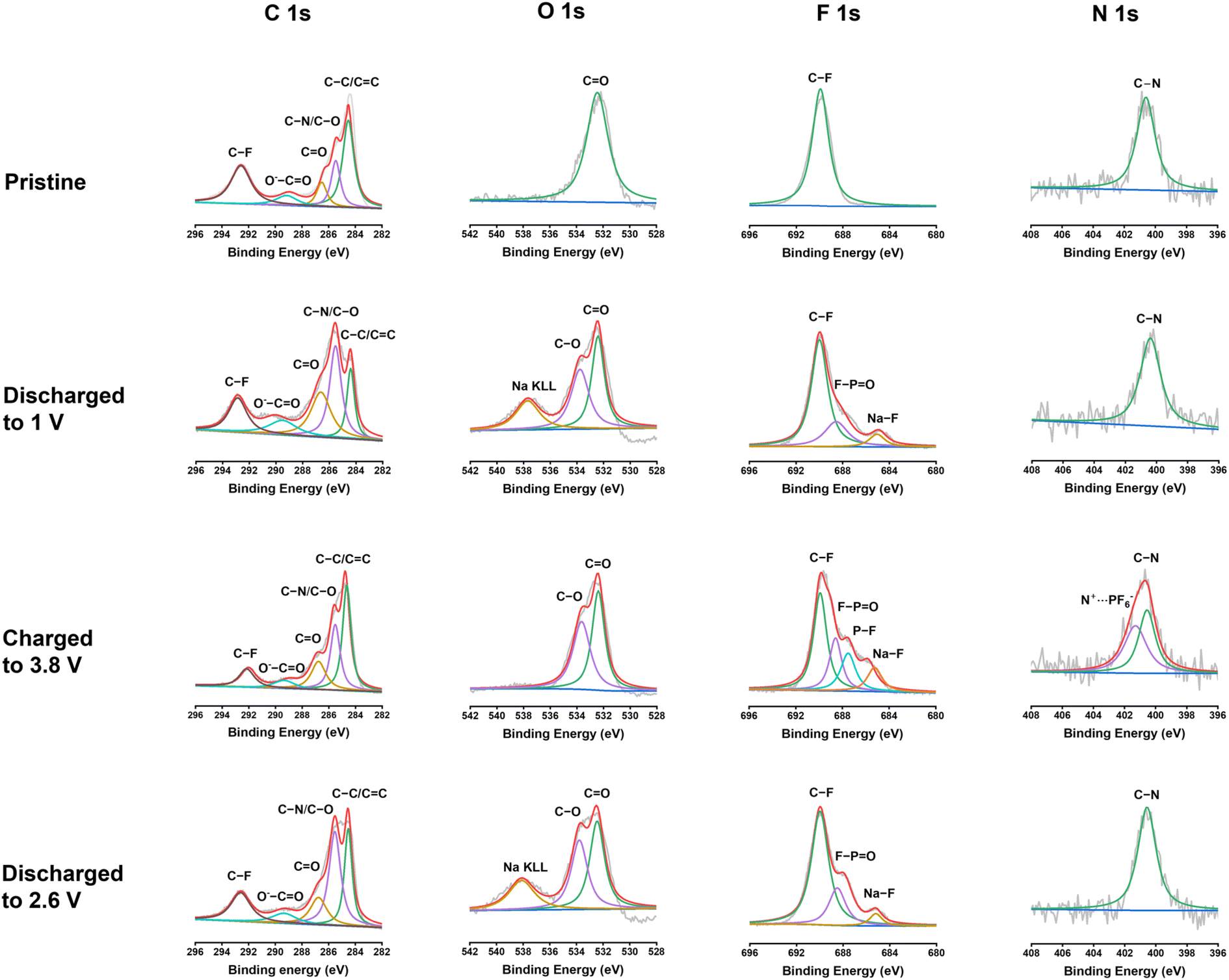 | ||
| Fig. 6 XPS spectra of the PNT cathode before and after cycling at the voltage window of 1–3.8 V in NIBs. The C 1s, O 1s, F 1s, and N 1s spectra are displayed in columns, which show the corresponding depth profiling results. | ||
To investigate morphology and chemical changes in the polymer cathode before and after cycling, characterization techniques such as SEM and FTIR were used. SEM was employed to determine any post-cycling morphological change on the surface of the electrode. As shown in Fig. 7, the integrity of the electrode was preserved from the pristine cathode to the 20th cycle. The polymeric microparticles covered with graphene flakes maintained similar irregular shapes upon cycling. FTIR spectra did not show any alteration from the pristine cathode to the 20th cycle (Fig. S20†), demonstrating high morphological and chemical stability of the polymer cathodes upon cycling.
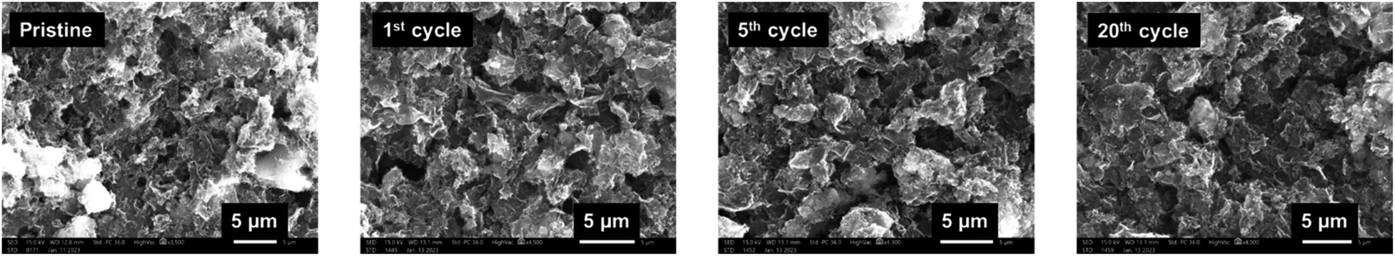 | ||
| Fig. 7 SEM images of the pristine and cycled PNT/single-layer graphene cathodes in NIBs. | ||
Conclusion
In summary, a class of bipolar mesoporous polymers with multiple n-type carbonyl moieties and p-type diamine moieties in the repeating units were synthesized via a facile condensation polymerization. Possessing the bipolar characteristic and unique growth of polymer chains in more than one direction, the porous polymers delivered superb electrochemical performances in both NIBs and KIBs in terms of high redox potentials, high capacity, long cycle life, and fast reaction kinetics. Extended conjugation structures in the polymers, together with the π–π stacking between the polymer and single-layer graphene, boosted the ion/electron transfer in the polymer cathodes, further improving the capacity, stability, and fast charging capability. XPS was employed to confirm the reversible redox reactions in the bipolar mesoporous polymers and the formation of NaF-based CEI after cycling. SEM and FTIR results indicate great morphological and chemical stability of the polymer cathodes upon long-term cycling. Therefore, this work demonstrates that developing bipolar porous polymers is a promising strategy for achieving high-performance and sustainable NIBs and KIBs.Experimental
Naphthalenetetracarboxylic dianhydride (>97%) and N,N,N′,N′-tetrakis(4-aminophenyl)-1,4-phenylenediamine (>95%) were purchased from TCI and Biosynth respectively, and they were used as received. Dimethylformamide (99.8%) was purchased from Sigma-Aldrich and stirred for 24 h with magnesium sulfate to remove any trace of water before using it for synthesis. Propionic acid (>99%) was purchased from Fisher Scientific. The single-layer graphene was received from ACS materials and carbon black (Super P) with above 99% purity was purchased from Alfa Aesar. The binder solution was prepared using sodium alginate purchased from MP Biomedicals. Electrolyte solvents including ethylene carbonate (>99%) and propylene carbonate (99.7%) were purchased from Sigma Aldrich.Polymer synthesis
PNT, PPM, and PBP were synthesized by a one-pot polycondensation reaction mainly following a reported procedure.46 Naphthalenetetracarboxylic dianhydride (0.8 mmol) was dissolved in 30 mL of dimethylformamide (DMF) in a 100 mL three-necked flask under refluxing and degassing in a 170 °C oil bath. N,N,N′,N′-Tetrakis(4-aminophenyl)-1,4-phenylenediamine (0.4 mmol) was dissolved in 10 mL of DMF and added dropwise to the solution. To induce the process, 10 mL of propionic acid was added to the mixture and stirring continued under a nitrogen atmosphere for 20 hours. The precipitations were collected by centrifuge and washed with tetrahydrofuran, methanol, acetone, and dichloromethane, respectively. The obtained fluffy powders were dried at 100 °C in a vacuum oven overnight.PPT was also synthesized by a one-pot polymerization according to a literature procedure.47 Perylenetetracarboxylic dianhydride (0.3 mmol) was added to 50 g imidazole and stirred at 150 °C under nitrogen until the imidazole chunks were melted and dissolved the dianhydride. N,N,N′,N′-Tetrakis(4-aminophenyl)-1,4-phenylenediamine (0.15 mmol) in 10 mL DMF was added drop by drop to the above solution. The mixture was stirred in a 170 °C oil bath for 20 h. After completion of the reaction, the flask was cooled down to 100 °C, and 100 mL of methanol was added. The precipitate was collected by filtration and was washed with DMF and ethanol subsequently. The resulting powder was also washed with tetrahydrofuran, methanol, acetone, and dichloromethane.
Characterization
X-ray diffraction (XRD) pattern was recorded by Rigaku MiniFlex using CuKα radiation; Fourier-transform infrared spectroscopy (FTIR) was recorded by Agilent Cary 630 FTIR Spectrometer; Solid-state magic-angle spinning (MAS) NMR experiments were run on a Bruker Avance NEO solid-state 500 MHz NMR spectrometer with a double resonance H/F-X probe: cross-polarization (CP) and magic-angle spinning was used for collecting 13C and 17O NMR spectra were obtained by direct observation with MAS. Briefly, samples were packed in a 3.2 mm outer diameter zirconia rotor with Kel–F endcap spinning at 10 kHz for 13C and 17O. Proton-carbon matched cross polarization ramp was at 50 kHz with 2 ms contact time. The proton dipolar decoupling was achieved by applying continuous wave spinal64 on the 1H channel during acquisition. The π/2 pulse length was 2.5 μs for 1H and the recycle delay was 4 s. Each 13C spectrum was collected with 2048 scans and the line broadening for the spectrum was 50 Hz. Each 17O spectrum was collected from 184![[thin space (1/6-em)]](https://www.rsc.org/images/entities/char_2009.gif) 320 to 327680 scans with a recycle delay of 0.5 s and the line broadening for the spectrum was 100 Hz. 13C chemical shifts were referenced with respect to TMS by setting δ(13C) = 0 ppm, and 17O chemical shifts were referenced with respect to water by setting δ(17O) = 0 ppm. Scanning electron microscopy (SEM) images were taken by JEOL JSM-IT500HR; XPS measurements were carried out at a PHI 5000 VersaProbe II system (Physical Electronics) spectrometer, which is equipped with a hemispherical analyzer. The spectrometer is attached to the Ar glovebox and sample transfer was directly through it to avoid any contact of the samples with air and moisture. The spectrometer is attached to the Ar glovebox and sample transfer was directly through it to avoid any contact of the samples with air and moisture. Monochromatic Al-Kα excitation (hν = 1486.6 eV) was used at a power of 25 W, additionally applying a low-energy electron charge neutralizer. The high-resolution spectrum of each element was collected with a pass energy of 23.25 eV in an analysis area of 100 × 100 μm. The binding energy scale was corrected based on the C 1s peak from contaminations (C–C at 284.4 eV) as the internal binding energy standard. The Brunauer–Emmett–Teller (BET) measurements were performed by Micromeritics ASAP 2020 Plus.
320 to 327680 scans with a recycle delay of 0.5 s and the line broadening for the spectrum was 100 Hz. 13C chemical shifts were referenced with respect to TMS by setting δ(13C) = 0 ppm, and 17O chemical shifts were referenced with respect to water by setting δ(17O) = 0 ppm. Scanning electron microscopy (SEM) images were taken by JEOL JSM-IT500HR; XPS measurements were carried out at a PHI 5000 VersaProbe II system (Physical Electronics) spectrometer, which is equipped with a hemispherical analyzer. The spectrometer is attached to the Ar glovebox and sample transfer was directly through it to avoid any contact of the samples with air and moisture. The spectrometer is attached to the Ar glovebox and sample transfer was directly through it to avoid any contact of the samples with air and moisture. Monochromatic Al-Kα excitation (hν = 1486.6 eV) was used at a power of 25 W, additionally applying a low-energy electron charge neutralizer. The high-resolution spectrum of each element was collected with a pass energy of 23.25 eV in an analysis area of 100 × 100 μm. The binding energy scale was corrected based on the C 1s peak from contaminations (C–C at 284.4 eV) as the internal binding energy standard. The Brunauer–Emmett–Teller (BET) measurements were performed by Micromeritics ASAP 2020 Plus.
Electrochemical measurements
The polymeric cathodes were fabricated using PNT/PPT/PPM/PBP, carbon black (CB), and sodium alginate (SA) in a ratio of 6:3:1 to form a smooth slurry. The composite cathodes of PNT/PPT were fabricated with PNT/PPT, single-layer graphene, CB, and SA in the ratio of 6:2:1:1. The electrodes were prepared by casting the slurry onto aluminum foil using a doctor blade and dried in a vacuum oven at 100 °C overnight. The dried film was punched into circular electrodes with an average mass loading of 1.9 mg cm−2. For the XPS analyses, PNT was mixed with CB and polytetrafluoroethylene (PTFE) in a ratio of 6:3:1 to form electrodes. The coin cells for Na-ion half cells were assembled using sodium metal as the counter electrode, 1 M NaPF6 in a mixture of ethylene carbonate (EC):propylene carbonate (PC) with a ratio of 1:1 (vol%) as the electrolytes, and glass fiber (Whatman) as the separator. The K-ion cells were assembled using potassium metal as the counter electrode, 1 M KPF6 in EC:PC, and glass fiber as the separator. The electrochemical performance was tested using an Arbin battery test station. Cyclic voltammograms were recorded by Gamry Reference 1010E potentiostat/galvanostat/ZRA with a scan rate of 0.1–1.0 mV s−1. Impedance analysis was also performed by Gamry Reference 1010E potentiostat/galvanostat/ZRA.
The theoretical capacity has been calculated using the equation below, where n is the number of electrons participating in the redox reaction, F is the Faraday constant, and M is the molecular weight of the repeating unit of polymers:
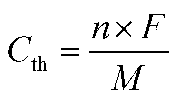
Based on the reaction mechanism, the theoretical capacities for PNT and PPT are 207.2 mA h g−1 and 177.9 mA h g−1, respectively.
Author contributions
Motahareh Mohammadiroudbari: investigation, validation, visualization, methodology, writing – original draft; Jinghao Huang: validation, methodology; Eric Youngsam Kim: validation, methodology; Dr Zhenzhen Yang: methodology, writing – review & editing; Dr Fu Chen: methodology, writing – review & editing; Dr Chao Luo: conceptualization, supervision, funding acquisition, project administration, writing – review & editing.Conflicts of interest
There are no conflicts to declare.Acknowledgements
This work was supported by the US National Science Foundation Award No. 2000102. The authors also acknowledge the support from the George Mason University Quantum Science & Engineering Center. We gratefully acknowledge support from the Post Test Facility at Argonne National Laboratory, which is operated for DOE Office of Science by UChicago Argonne, LLC, under contract number DE-AC02-06CH11357. We thank the NSF (NSF-1726058) for funding a solid-state NMR spectrometer.References
- M. Li, J. Lu, Z. Chen and K. Amine, Adv. Mater., 2018, 30, 1–24 Search PubMed.
- D. Deng, Energy Sci. Eng., 2015, 3, 385–418 CrossRef.
- T. Kim, W. Song, D. Y. Son, L. K. Ono and Y. Qi, J. Mater. Chem. A, 2019, 7, 2942–2964 RSC.
- K. Qin, K. Holguin, M. Mohammadiroudbari, J. Huang, E. Y. S. Kim, R. Hall and C. Luo, Adv. Funct. Mater., 2021, 31, 1–36 Search PubMed.
- H. Huang, R. Xu, Y. Feng, S. Zeng, Y. Jiang, H. Wang, W. Luo and Y. Yu, Adv. Mater., 2020, 32, 1–11 Search PubMed.
- S. Dhir, S. Wheeler, I. Capone and M. Pasta, Chem, 2020, 6, 2442–2460 CAS.
- E. J. Kim, P. R. Kumar, Z. T. Gossage, K. Kubota, T. Hosaka, R. Tatara and S. Komaba, Chem. Sci., 2022, 13, 6121–6158 RSC.
- X. Yin, S. Sarkar, S. Shi, Q. A. Huang, H. Zhao, L. Yan, Y. Zhao and J. Zhang, Adv. Funct. Mater., 2020, 30, 1–21 Search PubMed.
- Q. Pan, D. Gong and Y. Tang, Energy Storage Mater., 2020, 31, 328–343 CrossRef.
- J. J. Shea and C. Luo, ACS Appl. Mater. Interfaces, 2020, 12, 5361–5380 CrossRef CAS.
- M. Mohammadiroudbari, K. Qin and C. Luo, Batteries Supercaps, 2022, 5, e202200021 CAS.
- K. Holguin, M. Mohammadiroudbari, K. Qin and C. Luo, J. Mater. Chem. A, 2021, 9, 19083–19115 RSC.
- Y. Lu and J. Chen, Nat. Rev. Chem., 2020, 4, 127–142 CrossRef CAS PubMed.
- K. Qin, K. Holguin, J. Huang, M. Mohammadiroudbari, F. Chen, Z. Yang, G. L. Xu and C. Luo, Adv. Sci., 2022, 9, 1–14 Search PubMed.
- F. A. Obrezkov, A. F. Shestakov, V. F. Traven, K. J. Stevenson and P. A. Troshin, J. Mater. Chem. A, 2019, 7, 11430–11437 RSC.
- S. Gu, Y. Chen, R. Hao, J. Zhou, I. Hussain, N. Qin, M. Li, J. Chen, Z. Wang, W. Zheng, Q. Gan, Z. Li, H. Guo, Y. Li, K. Zhang and Z. Lu, Chem. Commun., 2021, 57, 7810–7813 RSC.
- M. Ruby Raj, R. V. Mangalaraja, D. Contreras, K. Varaprasad, M. V. Reddy and S. Adams, ACS Appl. Energy Mater., 2020, 3, 240–252 CrossRef CAS.
- S. Muench, A. Wild, C. Friebe, B. Häupler, T. Janoschka and U. S. Schubert, Chem. Rev., 2016, 116, 9438–9484 CrossRef CAS PubMed.
- J. Kim, J. H. Kim and K. Ariga, Joule, 2017, 1, 739–768 CrossRef CAS.
- C. Huangfu, Z. Liu, X. Lu, Q. Liu, T. Wei and Z. Fan, Energy Storage Mater., 2021, 43, 120–129 CrossRef.
- B. Tian, J. Zheng, C. Zhao, C. Liu, C. Su, W. Tang, X. Li and G. H. Ning, J. Mater. Chem. A, 2019, 7, 9997–10003 RSC.
- Y. Hu, H. Ding, Y. Bai, Z. Liu, S. Chen, Y. Wu, X. Yu, L. Fan and B. Lu, ACS Appl. Mater. Interfaces, 2019, 11, 42078–42085 CrossRef CAS PubMed.
- H. Wang, H. Wang, H. Wang, C. J. Yao, H. J. Nie, K. Z. Wang, Y. W. Zhong, P. Chen, S. Mei, Q. Zhang and Q. Zhang, J. Mater. Chem. A, 2020, 8, 11906–11922 RSC.
- Y. Huang, K. Li, J. Liu, X. Zhong, X. Duan, I. Shakir and Y. Xu, J. Mater. Chem. A, 2017, 5, 2710–2716 RSC.
- J. Li, M. Luo, Z. Ba, Z. Wang, L. Chen, Y. Li, M. Li, H. B. Li, J. Dong, X. Zhao and Q. Zhang, J. Mater. Chem. A, 2019, 7, 19112–19119 RSC.
- R. Van Der Jagt, A. Vasileiadis, H. Veldhuizen, P. Shao, X. Feng, S. Ganapathy, N. C. Habisreutinger, M. A. Van Der Veen, C. Wang, M. Wagemaker, S. Van Der Zwaag and A. Nagai, Chem. Mater., 2021, 33, 818–833 CrossRef CAS PubMed.
- G. Dai, Y. He, Z. Niu, P. He, C. Zhang, Y. Zhao, X. Zhang and H. Zhou, Angew. Chem., Int. Ed., 2019, 58, 9902–9906 CrossRef CAS PubMed.
- H. guo Wang, Q. Li, Q. Wu, Z. Si, X. Lv, X. Liang, H. Wang, L. Sun, W. Shi and S. Song, Adv. Energy Mater., 2021, 11, 1–9 Search PubMed.
- S. I. Etkind, J. Lopez, Y. G. Zhu, J. H. Fang, W. J. Ong, Y. Shao-Horn and T. M. Swager, ACS Sustainable Chem. Eng., 2022, 10, 11739–11750 CrossRef CAS.
- M. Li, J. Case and S. D. Minteer, ChemElectroChem, 2021, 8, 1215–1232 CrossRef CAS.
- T. Liu, K. C. Kim, B. Lee, S. Jin, M. J. Lee, M. Li, S. Noda, S. S. Jang and S. W. Lee, ACS Appl. Energy Mater., 2020, 3, 3728–3735 CrossRef CAS.
- M. G. Mohamed, S. U. Sharma, C. H. Yang, M. M. Samy, A. A. K. Mohammed, S. V. Chaganti, J. T. Lee and S. Wei-Kuo, ACS Appl. Energy Mater., 2021, 4, 14628–14639 CrossRef CAS.
- D. Luo, M. Li, Q. Ma, G. Wen, H. Dou, B. Ren, Y. Liu, X. Wang, L. Shui and Z. Chen, Chem. Soc. Rev., 2022, 51, 2917–2938 RSC.
- F. Y. Chou, J. C. Tang, H. Y. Lee, J. C. Lee, S. Ratchahat, T. H. Chen and W. Kaveevivitchai, ACS Appl. Energy Mater., 2020, 3, 11300–11306 CrossRef CAS.
- A. I. Cooper, Adv. Mater., 2009, 21, 1291–1295 CrossRef CAS.
- K. S. Weeraratne, A. A. Alzharani and H. M. El-Kaderi, ACS Appl. Mater. Interfaces, 2019, 11, 23520–23526 CrossRef CAS PubMed.
- G. Li and Z. Wang, J. Phys. Chem. C, 2013, 117, 24428–24437 CrossRef CAS.
- K. Sakaushi, E. Hosono, G. Nickerl, H. Zhou, S. Kaskel and J. Eckert, J. Power Sources, 2014, 245, 553–556 CrossRef CAS.
- X. Zhang, G. Zhu, M. Wang, J. Li, T. Lu and L. Pan, Carbon, 2017, 116, 686–694 CrossRef CAS.
- B. C. Patra, S. K. Das, A. Ghosh, A. K. Raj, P. Moitra, M. Addicoat, S. Mitra, A. Bhaumik, S. Bhattacharya and A. Pradhan, J. Mater. Chem. A, 2018, 6, 16655–16663 RSC.
- M. Wu, Y. Zhao, B. Sun, Z. Sun, C. Li, Y. Han, L. Xu, Z. Ge, Y. Ren, M. Zhang, Q. Zhang, Y. Lu, W. Wang, Y. Ma and Y. Chen, Nano Energy, 2020, 70, 104498 CrossRef CAS.
- T. Sun, J. Xie, W. Guo, D. S. Li and Q. Zhang, Adv. Energy Mater., 2020, 10, 1–23 Search PubMed.
- J. Liu, P. Lyu, Y. Zhang, P. Nachtigall and Y. Xu, Adv. Mater., 2018, 30, 1–8 CAS.
- J. S. M. Lee and A. I. Cooper, Chem. Rev., 2020, 120, 2171–2214 CrossRef CAS PubMed.
- H. Li, M. Tang, Y. Wu, Y. Chen, S. Zhu, B. Wang, C. Jiang, E. Wang and C. Wang, J. Phys. Chem. Lett., 2018, 9, 3205–3211 CrossRef CAS.
- D. Tian, H. Z. Zhang, D. S. Zhang, Z. Chang, J. Han, X. P. Gao and X. H. Bu, RSC Adv., 2014, 4, 7506–7510 RSC.
- M. R. Raj, N. Kim and G. Lee, Sustainable Energy Fuels, 2021, 5, 175–187 RSC.
- E. R. Andrew, A. Bradbury and R. G. Eades, Nature, 1959, 183, 1802–1803 CrossRef CAS.
- I. J. Lowe, Phys. Rev. Lett., 1959, 2, 285 CrossRef CAS.
- L. Xu, S. Zhang, P. Guo and C. Su, ChemistrySelect, 2021, 6, 4725–4735 CrossRef CAS.
- K. Sakaushi, E. Hosono, G. Nickerl, H. Zhou, S. Kaskel and J. Eckert, J. Power Sources, 2014, 245, 553–556 CrossRef CAS.
- H. Banda, D. Damien, K. Nagarajan, M. Hariharan and M. M. Shaijumon, J. Mater. Chem. A, 2015, 3, 10453–10458 RSC.
- M. Ruby Raj, R. V. Mangalaraja, G. Lee, D. Contreras, K. Zaghib and M. V. Reddy, ACS Appl. Energy Mater., 2020, 3, 6511–6524 CrossRef CAS.
- M. C. Biesinger, Appl. Surf. Sci., 2022, 597, 153681 CrossRef CAS.
- B. Deng, J. Li, H. Shang, W. Liu, Q. Wan, M. Chen, M. Qu and G. Peng, Ionics, 2020, 26, 2247–2257 CrossRef CAS.
Footnote |
| † Electronic supplementary information (ESI) available. See DOI: https://doi.org/10.1039/d3ta02445h |
| This journal is © The Royal Society of Chemistry 2023 |