
 Open Access Article
 This Open Access Article is licensed under a Creative Commons Attribution-Non Commercial 3.0 Unported Licence
Novel entropy-stabilized fluorite oxides with multifunctional properties†
Ashutosh
Kumar
 ,
David
Bérardan
,
Francois
Brisset
,
Diana
Dragoe
and
Nita
Dragoe
*
,
David
Bérardan
,
Francois
Brisset
,
Diana
Dragoe
and
Nita
Dragoe
*
Université Paris-Saclay, CNRS, ICMMO, Orsay 91400, France. E-mail: nita.dragoe@universite-paris-saclay.fr
First published on 25th May 2023
Abstract
Development of new high-entropy oxides having configurational entropy dominating the phase stability has become a hot topic since the discovery of rock salt structure entropy-stabilized (MgCoNiCuZn)O in 2015. Herein, we report a set of novel entropy-stabilized fluorite oxides: Zr0.2Hf0.2Ce0.2Sn0.2Mn0.2O2−δ, Zr0.2Hf0.2Ti0.2Mn0.2Ce0.2O2−δ, Zr0.225Hf0.225Ti0.225Mn0.225Ce0.1O2−δ, and Zr0.2Hf0.2Ti0.2Mn0.2Ce0.1Ta0.05Fe0.05O2−δ synthesized using standard solid-state reactions. These compounds have been investigated using X-ray diffraction, scanning electron microscopy, and X-ray photoelectron spectroscopy techniques to discern their structural, microstructural, and chemical properties. The configurational-entropy dominated phase stability and hence the entropy stabilization of the compounds are confirmed by cyclic heat treatments. The mismatch between the ionic radii and oxidation states of the cations is the key factor in achieving a single-phase fluorite structure. Furthermore, screening of physical properties, including thermal conductivity and optical band gap, and magnetic properties and impedance spectroscopy studies are discussed. A thermal conductivity of 1.4–1.7 W m−1 K−1 is observed at 300 K and remains invariant across a wide temperature range (300–1073 K), favorable for thermal barrier coating applications. These entropy-stabilized samples have an optical band gap of 1.6–1.8 eV, enabling light absorption across the visible spectrum and hence could be promising for photocatalytic applications. The impedance spectroscopy data of the entropy-stabilized samples reveal the presence of electronic contributions with a small activation energy (0.3–0.4 eV) across a temperature range of 298–423 K. These observations in entropy-stabilized fluorite systems show potential for their multifunctional applications via further optimization and confirm the great chemical versatility of entropy-stabilized oxides.
I. Introduction
The discovery of novel materials with enhanced functional properties is besought by the increasing dependence of humankind on technology. Among the many recent discoveries, entropy-stabilized oxides (ESOs) are a new class of ceramic materials where, in general, five or more cations in an equimolar ratio are integrated at a single crystallographic site to achieve entropic dominance over Gibb's free energy that drives the thermodynamic stability.1,2 These materials were discovered when Rost et al.3 extended the high-entropy alloy concept (Cantor et al.,4 and Yeh et al.5) to ionic bonded ceramics and synthesized the first entropy-stabilized oxide, (Mg0.2Co0.2Ni0.2Cu0.2Zn0.2)O with a rock-salt structure, which drove an impetus in materials science research based on ceramics. It was followed by the findings of new high-entropy materials with different crystal structures which include fluorite,6,7 spinels,8–10 bixbyite,11 perovskites,12 rutile,13 pyrochlore,14–16etc. These high-entropy oxides show interesting physical properties such as large lithium-ion conductivity,17 ultralow thermal conductivity,18 improved figure of merit for thermoelectrics,19 exotic magnetic ordering,10,20 colossal dielectric constant,21 proton conductivity,22 photocatalysis,23,24etc. Therefore, they constitute a very exciting playground for the development of new functional oxides.It should be noted that the terms high-entropy and entropy-stabilized oxides have often been used interchangeably in the literature although they refer to two different concepts.1,2,25 Populating a specific site with multiple cations results in high configurational entropy; however, for the system to be entropy-stabilized, it should possess both high configurational entropy along with positive enthalpy of mixing, indicating that the thermodynamic stability is driven by entropy.26 It is known that the Gibbs free energy of mixing (ΔGmix) should reduce in order to form a single phase and is influenced by the change in enthalpy of mixing (ΔHmix) and change in entropy of mixing (ΔSmix) as ΔGmix = ΔHmix − TΔSmix., where 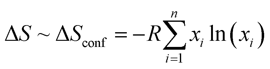 with xi as the molar concentration and n as the number of components. It is evident that for the case with ΔHmix < 0 and ΔHmix = 0 (ideal solution), ΔGmix is negative and favors the formation of a single-phase except when ΔHmix ≪ 0 leading to the formation of line compounds.27 Oppositely, a positive ΔHmix > 0 due to the differences in atomic sizes or electronegativity generally precludes the formation of single-phase compounds. Therefore, high configurational entropy is required to dominate the free energy prospect and overcome the positive ΔHmix. The entropy-stabilized phases have a dependence on the decreased/increased contribution of configurational entropy at low/high temperatures (TΔSmix). Thus, a reversible phase transformation of lower-temperature (enthalpy favorable) multiple phases to high-temperature (entropy-stabilized) single-phase compounds constitutes a signature for entropy-stabilization. This phase transition is endothermic in nature when screened using differential scanning calorimetric analysis.3 Therefore entropy-stabilization of a compound can be tested via cyclic heat treatment coupled with X-ray diffraction, differential scanning calorimetry, scanning electron microscopy, etc. For example, several recent studies including (Ce0.2La0.2Pr0.2Sm0.2Y0.2)O2−δ,28 (LaNdPrSmEu)1−xSrx(Co/Mn)O3,19,20 (Co0.2Cr0.2Fe0.2Mn0.2Ni0.2)3O4,29etc., do not show reversible phase transformation and are termed as high-entropy systems but not entropy-stabilized. The upholding of the single-phase in these systems may be attributed to the favorable enthalpy of mixing (ΔHmix < 0) with minimum influence of configurational entropy (TΔSmix). Some empirical selection rules have been suggested to synthesize entropy-stabilized oxides that include: the difference between the ionic radii of different cations at the single crystallographic site should be small, one of the cations should have a different usual local environment (for example in the case of (Mg0.2Co0.2Ni0.2Cu0.2Zn0.2)O MgO, CoO and NiO crystallize in a rock salt structure whereas CuO and ZnO crystallize respectively in tenorite and wurtzite structures), the overall system should have distinctive electronegativity, etc., which are explained in detail elsewhere.1,3,7,30,31 However, only a small ionic radius mismatch is considered for designing high entropy oxides.
In 2018, Chen et al. reported the first entropy-stabilized fluorite, Zr0.2Hf0.2Ce0.2Ti0.2Sn0.2O2 with thermal conductivity (κ) ∼1.28 W m−1 K−1 at 300 K.6 Furthermore, Gild et al.,32 showed a series of high-entropy fluorite oxides, followed by synthesis of (Zr0.2Ce0.2Hf0.2Y0.2Al0.2)O2−δ by Wen et al.33 However, entropy-stabilization was not established in these systems (cyclic heat treatment or other methods were not shown). Ding et al.,34 and He et al.,35 reported a (Hf0.25Zr0.25Sn0.25Ti0.25)O2 system with an orthorhombic structure (space group: Pbcn); however, no evidence was provided to support their claim of entropy stabilization. High-entropy fluorite oxides also include reports by Djenadic et al. on equiatomic rare-earth oxides having high configurational entropy (Ce0.2La0.2Sm0.2Pr0.2Y0.2)O2−δ (ref. 7) followed by (Nd0.16Ce0.16La0.16Sm0.16Pr0.16Y0.16)O2−δ by Sarkar et al.11 Recently Kante et al., fabricated (CeLaSmPrY)O2−x fluorite thin films using sol–gel and pulsed laser deposition processes and showed their optical band gap.36 Also, Chen et al., showed a series of samples where each element in Zr0.2Hf0.2Ce0.2Ti0.2Sn0.2O2 is replaced by Ca to further enlarge the fluorite family and concluded that Ce is important to realize single-phase high-entropy fluorite oxides.37 In this article, we explore a set of novel entropy-stabilized fluorite oxides in which the constituent elements are chosen to ensure a positive change in enthalpy (ΔHmix > 0, which originates from differences in the ionic radii, electronegativity, and crystal structure of individual simple oxides) and high configurational entropy (equimolar concentration of five different elements) and in this process, we also reinvestigate the first reported high-entropy fluorite oxides by Chen et al.,6 and observe a peculiar structural behaviour on the surface and bulk in Zr0.2Hf0.2Ce0.2Ti0.2Sn0.2O2, attributed to the possible reduction of Ce4+ for this combination of elements. Furthermore, a deeper understanding of single-phase formation in high-entropy fluorite oxides is developed considering the possible role of oxygen vacancies and oxidation states of cations to synthesize new compositions and novel entropy-stabilized fluorite oxides: Zr0.2Hf0.2Ce0.2Sn0.2Mn0.2O2−δ, Zr0.2Hf0.2Ti0.2Mn0.2Ce0.2O2−δ, Zr0.225Hf0.225Ti0.225Mn0.225Ce0.1O2−δ, Zr0.2Hf0.2Ti0.2Mn0.2Ce0.1Ta0.05Fe0.05O2−δ synthesized using standard solid-state reaction routes are reported for the first time. These novel high-entropy fluorite samples are further screened using cyclic thermal treatment to establish the configurational entropy dominated phase stability which is further supported by scanning electron microscopy-energy dispersive X-ray spectroscopy (SEM-EDS) techniques. Last, preliminary studies of their physical properties including the optical band gap, thermal conductivity (κ), magnetic properties (M–H and M–T), low-temperature specific heat capacity, and impedance spectroscopy (IS) studies have been discussed.
II. Experimental section
High-entropy fluorite samples were synthesized using standard solid-state reaction methods. The details of oxide precursors used for each synthesis are shown in Table S1.† Stoichiometric amounts of oxide precursors for each composition were mixed using planetary ball milling (Fritsch Pulverisette 7 Premium Line) at 350 rpm for 60 cycles (5 min on and 5 min off time) in a wet medium (ethanol). The slurry obtained after ball milling was dried overnight inside an oven at 100 °C. The Sn-containing samples were calcined at 1300 °C for 6–8 hours with a heating and cooling rate of 200 °C per hour. The obtained powder was again ball milled and compressed into cylindrical pellets of 10 mm in diameter and 1.5–2 mm thickness. However, this intermediate calcination step was skipped for samples without Sn. The compacted pellet was placed on a platinum (Pt) sheet inside an alumina boat and sintered in the temperature range from 1380–1500 °C for 6–15 hours followed by fast quenching. Cyclic heat treatment was performed to establish the entropy-stabilized phase formation of the samples. The scheme for the synthesis and entropy-stabilization test is shown in Fig. 1. The exact temperature of sintering used for each sample is shown in Table 1.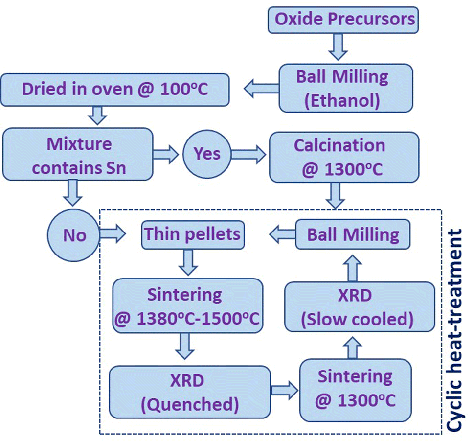 | ||
| Fig. 1 Schematic presentation of the synthesis cycle used for the preparation of high-entropy fluorite oxides. | ||
![[r with combining macron]](https://www.rsc.org/images/entities/i_char_0072_0304.gif) ), standard deviation (s), sintering temperature, configurational entropy, and the nature of the XRD pattern obtained from the surface (S) and powder (B) are shown for comparison (F: fluorite (Fm
), standard deviation (s), sintering temperature, configurational entropy, and the nature of the XRD pattern obtained from the surface (S) and powder (B) are shown for comparison (F: fluorite (Fm![[3 with combining macron]](https://www.rsc.org/images/entities/char_0033_0304.gif) m), O: orthorhombic (Pbcn), and P: pyrochlore ()). The elements in the parenthesis () are in the equimolar ratio. XRD patterns for (ZrHfTiCeY)O2−δ, (ZrHfCeY)O2−δ, (ZrHfCeYGd)O2−δ, (ZrHfCeYYb)O2−δ, and (ZrHfCeYbGd)O2−δ are shown in Fig. S7 of the ESI
m), O: orthorhombic (Pbcn), and P: pyrochlore ()). The elements in the parenthesis () are in the equimolar ratio. XRD patterns for (ZrHfTiCeY)O2−δ, (ZrHfCeY)O2−δ, (ZrHfCeYGd)O2−δ, (ZrHfCeYYb)O2−δ, and (ZrHfCeYbGd)O2−δ are shown in Fig. S7 of the ESI
| Sample |
|
s | T (°C) | S conf | Entropy stabilized | XRD: surface | XRD: bulk | Ref. |
|---|---|---|---|---|---|---|---|---|
| (ZrHfTiSnCe)O2 | 0.761 | 0.135 | 1500 | 1.61R | Yes: surface | F | F + O | 6, 34, and 35 |
| (ZrHfTiSnMn)O2−δ | 0.733 | 0.087 | 1500 | 1.61R | Yes: surface | F | F + O | This work |
| (ZrHfTiSn)0.8(CeY)0.2O2−δ | 0.754 | 0.138 | 1500 | 1.75R | Yes: surface | F | F + O | This work |
| (ZrHfTiSnY)O2−δ | 0.747 | 0.109 | 1500 | 1.61R | Yes: surface | F | F + O | This work |
| (ZrHfCeSnMn)O2 | 0.806 | 0.105 | 1500 | 1.61R | Yes | F | F | This work |
| (ZrHfTiCeY)O2−δ | 0.803 | 0.140 | 1500 | 1.61R | No | F + P | F + P | 32 |
| (ZrHfCeY)O2−δ | 0.853 | 0.099 | 1500 | 1.29R | No | F | F | 32 |
| (ZrHfCeYGd)O2−δ | 0.87 | 0.094 | 1500 | 1.61R | No | F + P | F + P | 32 |
| (ZrHfCeYYb)O2−δ | 0.855 | 0.086 | 1500 | 1.61R | No | F + P | F + P | 32 |
| (ZrHfCeYbGd)O2−δ | 0.863 | 0.093 | 1500 | 1.61R | No | F + P | F + P | 32 |
| (ZrHfTiNbY)O2−δ | 0.737 | 0.118 | 1500 | 1.61R | No | M | M | This work |
| (ZrHfTiMnCe)O2−δ | 0.789 | 0.132 | 1380 | 1.61R | Yes | F | F | This work |
| ((ZrHfTiMn)0.9Ce0.1)O2−δ | 0.766 | 0.134 | 1380 | 1.57R | Yes | F | F | This work |
| (ZrHfTiMn)0.8Ce0.1(TaFe)0.1O2−δ | 0.756 | 0.128 | 1380 | 1.66R | Yes | F | F | This work |
The structural characterization of the samples was performed by X-ray diffraction using a Panalytical X'Pert diffractometer with a Ge(111) incident monochromator, a copper tube (Kα1 radiation), and a fast detector (X'celerator). Surface morphology was observed and elemental mapping was performed using scanning electron microscopy (SEM-FEG Zeiss Sigma HD) equipped with energy-dispersive X-ray spectroscopy (SAMx-IDFix EDS) operating at 20 kV. Furthermore, X-ray photoelectron spectroscopy (XPS) measurements were performed on a Thermo Fisher Scientific instrument with a monochromatic Al-Kα X-ray source (energy 1486.68 eV) and a hemispherical analyzer. The base pressure was around 5 × 10⁻⁹ mbar and the diameter of the X-ray beam spot was 400 μm, corresponding to an irradiated surface of approximately 1 mm2. The hemispherical analyzer was operated at a 0° take-off angle in the constant analyzer energy (CAE) mode. Wide scan spectra were recorded at a pass energy of 200 eV and an energy step of 1 eV while narrow scan spectra were recorded at a pass energy of 50 eV and an energy step of 0.1 eV. Charge compensation was achieved by employing a “dual beam” flood gun, using low-energy electrons (<5 eV) and argon ions. The binding energy scale was calibrated on the neutral carbon set at 285 eV. The obtained core-level spectra were treated using CasaXPS software.21 The thermal conductivity (κ) of the samples was calculated using κ = DρsCp. The thermal diffusivity (D) was measured using the laser flash technique (Netzsch LFA 427), and sample density (ρs) was calculated using the mass of the pellet and its geometric volume. The specific heat capacity (Cp) was calculated using the Dulong–Petits law. The optical band gap was obtained from UV-visible spectroscopy measurement using an Agilent Cary 5000 UV-Vis-NIR spectrometer in diffuse reflective spectra (DRS) mode. The obtained reflectance data is converted into absorbance spectra using the Kubelka–Munk function. The magnetic measurements (M–H at 2 K and M–T in ZFC and FC modes at 100 Oe) were obtained using a SQUID magnetometer (MPMS, Quantum Design, USA). The electrical properties of entropy-stabilized samples were investigated using the impedance spectroscopy (IS) technique. The IS measurements were carried out on cylindrical samples coated with platinum on both sides (Pt/HEOx/Pt, using DC magnetron sputtering) at different temperatures in the frequency range of 0.01 to 3.3 × 10⁶ Hz and 300 mV disturbance amplitude. The samples were placed in a Swagelok-type casing that was then placed inside an oven for temperature-dependent measurements. The obtained IS data were analyzed using fit3Zarcs software.38 Electrical resistivity was also measured in the two-probe configuration using a Keithley source meter (Keithley 6517B) from 298–423 K. Low-temperature specific heat capacity measurements were carried out using a PPMS (Physical Property Measurement System, Quantum Design) across a temperature range of 2–300 K. The sample was kept in a vacuum of circa 0.01 mTorr and protected using an anti-radiation shield, to prevent dissipation from convection and thermal radiation respectively. An Apiezon N grease was used to ensure heat transfer from the sample to the sample holder.
III. Results and discussion
First, the outcome of the synthesis of the new composition Zr0.2Hf0.2Ti0.2Sn0.2Mn0.2O2−δ is shown in Fig. 2(a) at each step during synthesis. The XRD pattern of the ball-milled (BM) oxide precursors consists of peaks corresponding to each binary oxide used for the synthesis. Further calcination of mixed precursors at 1300 °C results in a multiphase compound, with a main orthorhombic phase (space group: Pbcn).34 After consolidating the powder into thin pellets and sintering at 1500 °C for 6 hours followed by quenching, the XRD pattern of the surface of the pellet (penetration depth of the XRD beam was estimated to be a few μm) evidences a single-phase fluorite structure with no impurity within the sensitivity of the XRD. In order to assess the role of configurational entropy in the formation of the compound, this pellet was further exposed to cyclic heat treatment. After heating at 1300 °C for 12 hours, the XRD pattern of the pellet shows the presence of multiple phases, which are reversed to a single-phase fluorite structure with further sintering at 1500 °C followed by quenching. The zoomed-in image in Fig. 2(a) shows the evolution of the main peak of the XRD pattern of the pellet during the different steps of thermal cycling, demonstrating entropy stabilization. At first glance, this observation confirms that the Zr0.2Hf0.2Ti0.2Sn0.2Mn0.2O2−δ phase may be entropy-stabilized. However, the powder obtained after grinding the single-phase pellet results in a very different and unexpected picture, as shown in Fig. 2(b). In this figure, a comparison of the XRD measurements performed on the calcined precursors at 1300 °C (bottom), the surface of the pellet sintered at 1500 °C (middle), and ground powder (bulk, top) is shown. It is seen that the XRD patterns of the surface (pellet) and bulk (powder) are very different. Although the XRD pattern of the pellet evidences a single-phase fluorite structure with the Fmm space group, the powder consists of a combination of fluorite and orthorhombic structures.34 At this stage, the origin of such a distinctive nature of XRD patterns on the surface and bulk is not very clear. Also, such an observation has never been reported in the literature for these high entropy compounds, to the best of our knowledge.
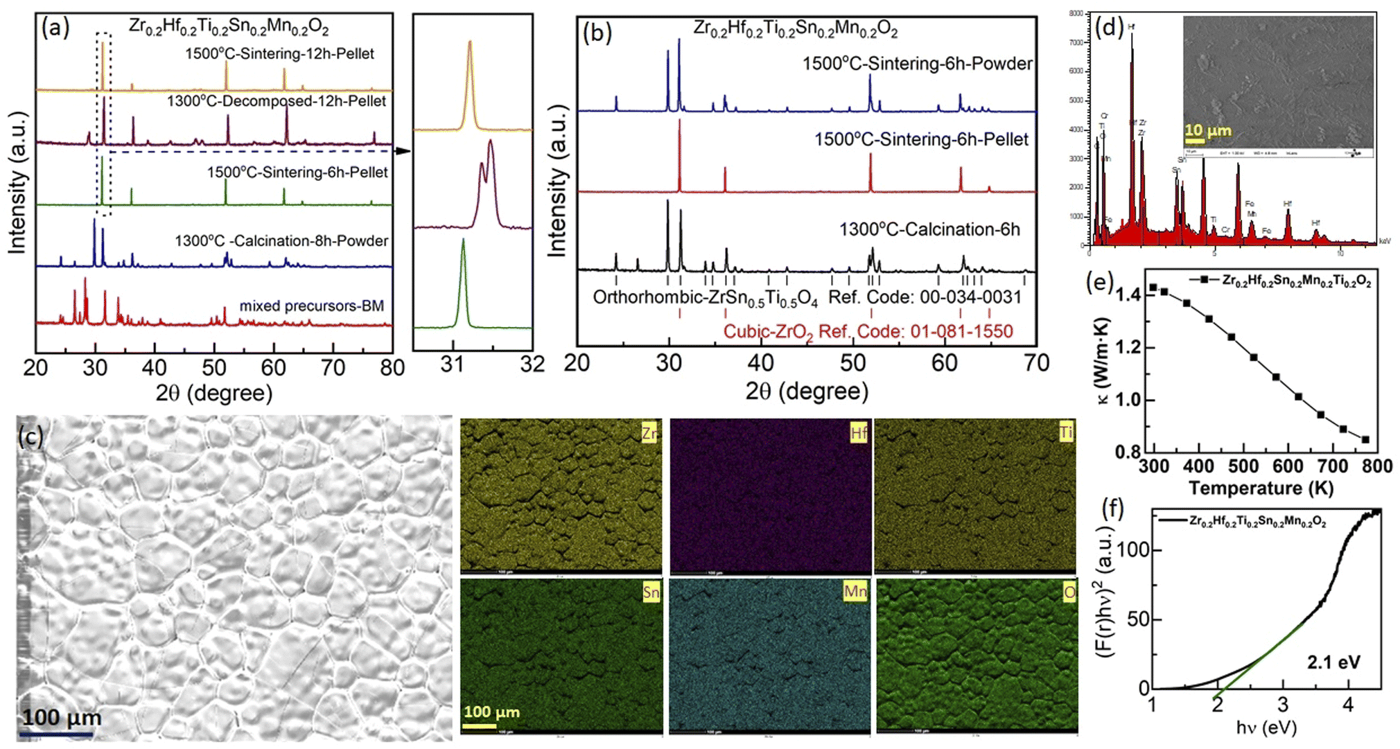 | ||
| Fig. 2 (a) X-ray diffraction patterns of Zr0.2Hf0.2Ti0.2Sn0.2Mn0.2O2−δ at different synthesis steps (mixed precursors using ball milling (BM), calcination, and final sintering) followed by the entropy-stabilization test. (b) XRD patterns obtained on the surface (pellet) and bulk (powder) samples sintered at 1500 °C and their comparison with the XRD pattern of the same sample calcined at 1300 °C. (c) Scanning electron microscopy (SEM) image and the corresponding elemental mapping of each element using energy dispersive X-ray spectroscopy (EDS). (d) Corresponding EDS spectra, inset: the SEM image of Zr0.2Hf0.2Ti0.2Sn0.2Mn0.2O2−δ. (e) Thermal conductivity (κ) and (f) band gap obtained from UV-visible spectroscopy for Zr0.2Hf0.2Ti0.2Sn0.2Mn0.2O2−δ. | ||
The energy dispersive X-ray spectroscopy (EDS) mapping performed on the surface of the pellet shows the homogeneous nature of the sample and further confirms that there is no impurity present on the surface (Fig. 2(c)). The EDS spectrum obtained from the surface of Zr0.2Hf0.2Ti0.2Sn0.2Mn0.2O2−δ is shown in Fig. 2(d). The atomic percentage obtained is in good agreement with the stoichiometric amounts of elements present in the system. Besides, the thermal conductivity at 300 K is 1.42 W m−1 K−1 (Fig. 2(e)) and is in close agreement with the value (1.28 W m−1 K−1) reported by Chen et al. for Zr0.2Hf0.2Ti0.2Sn0.2Ce0.2O2.6 Thermal conductivity decreases rapidly with an increase in temperature; however, the exact reason for such a change is difficult to understand in a multiphase sample. The optical band gap obtained from UV-visible spectroscopy for this sample is 2.1 eV (Fig. 2(f)).
Following this unexpected observation, we decided to reinvestigate the synthesis of the Zr0.2Hf0.2Ti0.2Sn0.2Ce0.2O2 compound following Chen et al.6 The XRD patterns corresponding to each step are shown in Fig. 3(a). Similar to our new Zr0.2Hf0.2Ti0.2Sn0.2Mn0.2O2−δ composition, they also show a single-phase fluorite structure on the pellet (surface), whereas the XRD pattern of the ground powder (bulk) corresponds to a multiphase sample with a predominant orthorhombic structure. This observation of a single-phase pattern on the surface (pellet) is consistent with the report by Chen et al.6 However, the nature of the samples that were analyzed by these authors using XRD was not mentioned in their report. Besides, the (mostly) orthorhombic nature of the XRD pattern for the powder samples agrees with the recent studies on four-component binary high-entropy oxides using similar elements.34,35 It is seen that the XRD pattern for the bulk is similar to the XRD pattern of the precursors calcined at 1300 °C, indicating that such a mixture could be difficult to convert back to single-phase fluorite at 1500 °C due to kinetic issues. In order to avoid this possible difficulty, a new synthesis is performed where the oxide precursors are mixed using ball milling and the mixture is consolidated into pellets and is directly sintered at 1500 °C followed by quenching. However, the XRD pattern (Fig. S1†) shows the distinctive nature of the diffraction pattern of the pellet and powder. Fig. S2(a)† shows the XRD pattern corresponding to each step during the synthesis of Zr0.2Hf0.2Ti0.2Sn0.2Ce0.2O2. Furthermore, two more similar compositions Zr0.2Hf0.2Ti0.2Sn0.2Ce0.1Y0.1O2−δ and Zr0.2Hf0.2Ti0.2Sn0.2Y0.2O2−δ have been synthesized and the XRD diffraction pattern depicts the different XRD patterns of the surface and bulk and is shown in Fig. S2(b) and (c).† A similar synthesis route has been followed for these two samples and a similar nature of the diffraction pattern has been observed. However, it should be noted that when one of the elements has an oxidation state lower than 4+, (in these cases: Y3+ or Mn2+ (shown later in XPS)), the fluorite phase appears significantly in the bulk phase as well, whereas it is hardly observed in Zr0.2Hf0.2Ti0.2Sn0.2Ce0.2O2. However, even in these cases, the samples still do not exhibit a single-phase fluorite structure. Several other compositions with Sn as one of the elements have been tried but no single-phase fluorite structure has been seen in the powder sample.
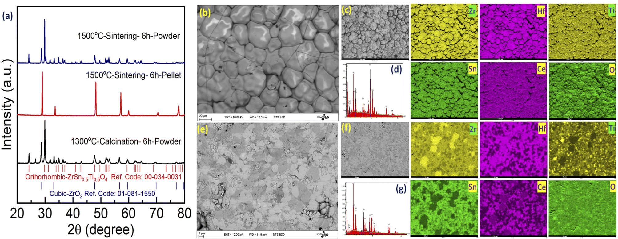 | ||
| Fig. 3 (a) X-ray diffraction pattern for Zr0.2Hf0.2Ti0.2Sn0.2Ce0.2O2 at each step. The XRD pattern on the pellet (surface) and powder (bulk) is shown. The Bragg's position corresponding to the orthorhombic and cubic phases is marked. Scanning electron microscopy images for Zr0.2Hf0.2Ti0.2Sn0.2Ce0.2O2 observed in backscattered electron (BSE) mode (b) on the surface and (e) on the bulk are shown. The elemental mapping and energy dispersive X-ray spectra (EDS) of the (c and d) surface and (f and g) bulk are shown. | ||
Furthermore, SEM-EDS is carried out on the surface and the cross-section of the Zr0.2Hf0.2Ti0.2Sn0.2Ce0.2O2 pellet. The corresponding backscattered electron (BSE) image on the surface and bulk is shown in Fig. 3(b) and (c). Interestingly, the surface shows no clear contrast whereas there is a contrast in the bulk of the pellet depicting the multiphase nature of the bulk sample. The mapping of each element and corresponding EDS spectra are shown for the surface (Fig. 3(d) and (e)) and bulk (Fig. 3(f) and (g)) respectively. The homogeneous distribution of elements may be seen on the surface; however, the cross-section mapping shows an inhomogeneous distribution, supporting the observation of the multiphase by XRD.
In order to further understand the different structures of the pellet and powder in Sn-containing sample Zr0.2Hf0.2Ti0.2Sn0.2Ce0.2O2, X-ray photoelectron spectroscopy is carried out on the surface of the pellet and powder. Fig. 4 shows the core-level spectra for each element present in Zr0.2Hf0.2Ti0.2Sn0.2Ce0.2O2. It is seen that Zr, Hf, Ti, and Sn show similar core-level spectra for the pellet and powder and are in the 4+ charge state. However, it is interestingly observed that core-level spectra of Ce show two distinct charge states (Ce4+ and Ce3+) and are similar in both powder and the pellet. The corresponding fitting is shown in Fig. S8† and fitting details are listed in Table S3.† The ratio Ce3+/Ce4+ was evaluated as proposed in ref. 39 and 40 and found to be 1.4 for both locations. The fitting procedure, implying a Shirley-type background subtraction and mixed Gaussian–Lorentzian line shapes was performed using both the Avantage and CasaXPS software and shows similar results. However, this value is not precise as CeO2 is known to reduce during X-ray exposure.41,42 In general, the fluorite structure is stabilized by oxygen deficiency, and to accommodate the overall charge neutrality Ce changes from Ce4+ to Ce3+, since all other elements are quite stable in 4+ charge states. Although the core-level spectra for all the cations are similar in bulk and surface, and only core-level spectra for O-1s, shown in Fig. 4, are observed to be different on the pellet and powder which may be the reason for such structural differences on the pellet and powder.
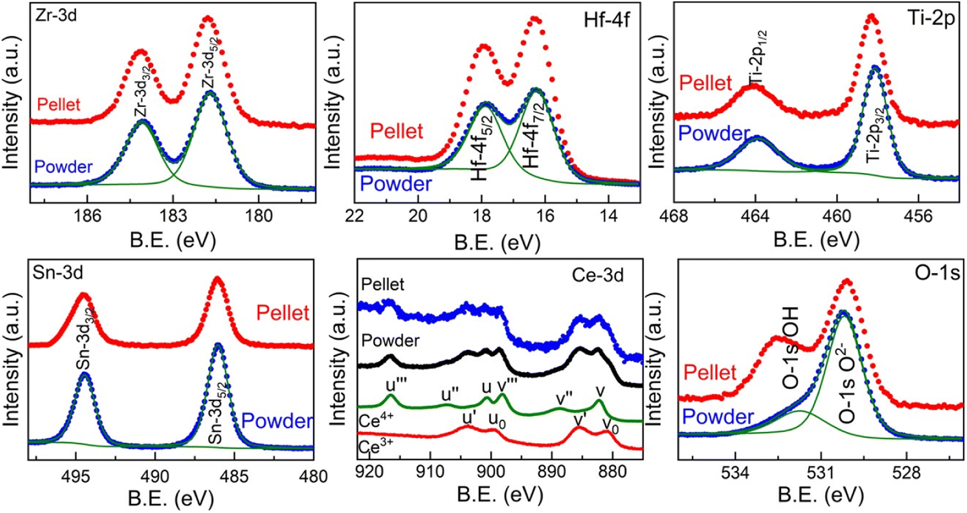 | ||
| Fig. 4 Core-level X-ray photoelectron spectroscopy (XPS) measurement carried out on the surface and bulk for each element in Zr0.2Hf0.2Ti0.2Sn0.2Ce0.2O2. | ||
There are several high-entropy fluorite oxides synthesized in the literature that possesses oxygen vacancies.7 Keeping these in mind, we then synthesized the Zr0.2Hf0.2Ce0.2Sn0.2Mn0.2O2−δ sample following the same synthesis route. The X-ray diffraction patterns, shown in Fig. 5(a), depict the single-phase fluorite structure on the surface as well as in the bulk. Rietveld refinement was performed on the bulk XRD pattern using Fullprof software43 with the Fmm space group, and the refinement is shown in Fig. 5(b). The lattice parameter obtained from the refinement for Zr0.2Hf0.2Ce0.2Sn0.2Mn0.2O2−δ is 5.136 Å and the corresponding crystal structure drawn using Vesta software44 is shown in Fig. 5(c). Fig. 5(d) shows the X-ray diffraction pattern of the cyclic heat treatment performed on Zr0.2Hf0.2Ce0.2Sn0.2Mn0.2O2−δ. It is seen that the sample is multiphase below a critical temperature and is reversed to the single phase when sintered at 1500 °C followed by quenching, establishing the entropy-dominated phase stability of this sample. Therefore, Zr0.2Hf0.2Ce0.2Sn0.2Mn0.2O2−δ seems to be the first entropy-stabilized single-phase fluorite oxide.
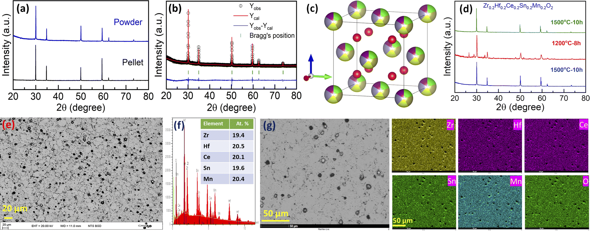 | ||
| Fig. 5 (a) X-ray diffraction pattern for Zr0.2Hf0.2Ce0.2Sn0.2Mn0.2O2−δ obtained on the pellet and powder. (b) Rietveld refinement pattern for Zr0.2Hf0.2Ce0.2Sn0.2Mn0.2O2−δ. (c) Crystal structure obtained from Vesta software using structural parameters obtained from the Rietveld refinement. (d) The cyclic heat treatment demonstrates the entropy-stabilized nature of the sample. (e) Backscattered electron (BSE) image, (f) energy-dispersive X-ray spectroscopy (EDS) pattern and (g) corresponding elemental mapping for Zr0.2Hf0.2Ce0.2Sn0.2Mn0.2O2−δ. | ||
Furthermore, the backscattered electron image of the Zr0.2Hf0.2Ce0.2Sn0.2Mn0.2O2−δ pellet (cross-section) is shown in Fig. 5(e), and the corresponding energy-dispersive X-ray spectrum (EDS) in Fig. 5(f). For the investigation of the microstructure, the surface of the pellet is polished using an automatic grinding/polishing machine. Due to polishing, the grains partly come out of the surface, as can be seen in the higher magnification image (Fig. 5(g)). The atomic percentage of elements obtained from EDS is in line with the stoichiometric amount of precursors used for the synthesis. The elemental mapping for each element present in Zr0.2Hf0.2Ce0.2Sn0.2Mn0.2O2−δ is shown in Fig. 5(g). The mapping is also performed on the cross-section of the pellet. The homogeneous distribution of each element present in this entropy-stabilized Zr0.2Hf0.2Ce0.2Sn0.2Mn0.2O2−δ further confirms the single-phase nature of the sample. A comparison of Zr0.2Hf0.2Ti0.2Sn0.2Mn0.2O2−δ (Fig. 2(a)) and Zr0.2Hf0.2Ce0.2Sn0.2Mn0.2O2−δ (Fig. 5(a)) shows that Ce seems to be essential to form a single-phase fluorite structure, as also suggested by Chen et al. in a recent study.37
The charge transport properties of the entropy-stabilized Zr0.2Hf0.2Ce0.2Sn0.2Mn0.2O2−δ sample are evaluated using impedance spectroscopy (IS) techniques. The measurements were performed using ionically blocking electrodes (Pt in the present case) on both sides of the pellet, as shown in Fig. S14.† The Bode plots consisting of the magnitude of the impedance |Z| and phase angle (ϕ) as a function of frequency at different temperatures are shown in Fig. S15(a) and (b).† The Nyquist plots (−ImZ vs. ReZ) for Zr0.2Hf0.2Ce0.2Sn0.2Mn0.2O2−δ at different temperatures are shown in Fig. 6(a). Nyquist plots provide visual cues that help us analyse experimental data and understand the physical processes of the samples studied using IS measurement. Experimentally a perfect semicircle in the Nyquist plot is rarely seen due to the overlap of processes with similar time constants and hence an equivalent circuit model is widely used. However, it is seen that the analysis of IS using the corresponding equivalent circuits is very difficult due to the possibility of overlap between different transport contributions. Therefore, the distribution of relaxation time (DRT) method has been promising in distinguishing the characteristic relaxation times corresponding to different transport processes.45,46 This method uses the inverse Fourier transform to change the frequency-dependent IS data to a distribution of time constants to determine the relaxation times contributing to the impedance spectrum.47,48
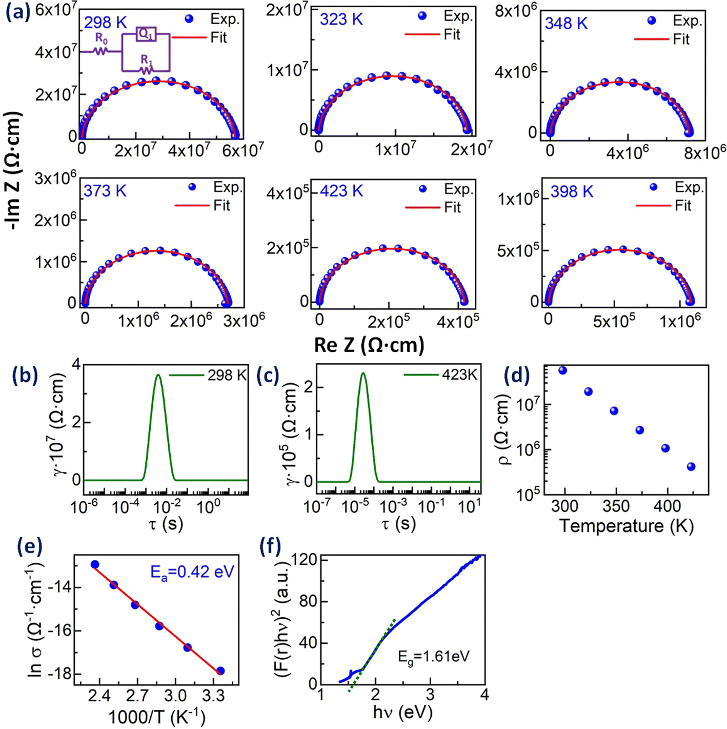 | ||
Fig. 6 (a) Nyquist plots for Zr0.2Hf0.2Ce0.2Sn0.2Mn0.2O2−δ at different temperatures and the corresponding single ZARC fit (the scheme is shown in the inset). The distribution of relaxation time (DRT) plots for Zr0.2Hf0.2Ce0.2Sn0.2Mn0.2O2−δ at (b) 298 K and (c) 423 K. (d) The electrical resistivity (ρ) as a function of temperature and (e) Arrhenius plot (ln![[thin space (1/6-em)]](https://www.rsc.org/images/entities/char_2009.gif) σ vs. 1000/T) for Zr0.2Hf0.2Ce0.2Sn0.2Mn0.2O2 and (f) optical band gap obtained from UV-Vis spectra in diffuse reflectance mode. σ vs. 1000/T) for Zr0.2Hf0.2Ce0.2Sn0.2Mn0.2O2 and (f) optical band gap obtained from UV-Vis spectra in diffuse reflectance mode. | ||
The DRT plot obtained for Zr0.2Hf0.2Ce0.2Sn0.2Mn0.2O2−δ to identify the number of processes involved in the transport process is shown in Fig. 6(b) and (c) at 298 K and 423 K for Zr0.2Hf0.2Ce0.2Sn0.2Mn0.2O2−δ. The DRT plot gives one dominant contribution and hence all the Nyquist plots are fitted with a single ZARC model, where a ZARC is defined as a parallel combination of a resistor (R) and constant phase element (Q) as shown in the inset of Fig. 6(a). As seen from the Nyquist plot, this sample does not show a capacitive tail at lower frequencies with Pt blocking electrodes. Thus, it is highly possible that the ionic conduction is negligible in this sample in this temperature range and that the only contribution to the electrical transport is electronic. The electrical resistivities obtained from the fitting are shown in Fig. 6(d), which is in line with the two-probe electrical resistivity measurement performed on this sample (not shown). The fitting parameters obtained from the ZARC fit are shown in Table S5.† Furthermore, these electrical resistivities are used to estimate the activation energy from the Arrhenius plot, as shown in Fig. 6(e). The activation energy (Ea) is 0.42 eV which is quite lower than the activation energy reported for Zr0.2Hf0.2Ce0.2Sn0.2Ti0.2O2.6
The UV-visible spectroscopy measurement is carried out at 300 K in diffuse reflectance spectra (DRS) mode to find the optical band gap for Zr0.2Hf0.2Ce0.2Sn0.2Mn0.2O2−δ. The Tauc method for estimating the band gap, based on the assumption of the energy-dependent absorption coefficient (α), is expressed as (αhν)1/n = A(hν − Eg), where h is the Planck constant, ν is the photon's frequency, Eg is the band gap, and A is a constant. The factor n depends on the nature of the electronic transition and is taken as 1/2 and 2 for direct and indirect transition band gaps, respectively. For the determination of the band gap in DRS mode, Kubelka and Munk suggested the transformation of measured reflectance spectra into the corresponding absorption spectra by applying the Kubelka–Munk function (F(r)), defined as  , where R is the reflectance of an infinitely thick specimen.49 Hence, the above equation reduces to (F(r)hν)1/n = A(hν − Eg). The direct band gap for Zr0.2Hf0.2Ce0.2Sn0.2Mn0.2O2−δ is calculated using the (F(r)hν)2vs. hν curve and is shown in Fig. 6(f). It is noted that the optical band gap for Zr0.2Hf0.2Ce0.2Sn0.2Ti0.2O2 is 3.05 eV (Fig. S11†) and it reduces to 1.61 eV for Zr0.2Hf0.2Ce0.2Sn0.2Mn0.2O2.
Next, we explore more compositions by following the selection rules which include the criteria of ionic radii and corresponding oxidation states of cations following Pauling rules (for structure and local coordination of cations). These criteria, similar to those of conventional oxide compounds, are decisive for establishing the phase stability of high-entropy oxides, although exceptions exist.12,30 Accordingly, the average value of cationic radii  and standard deviation
  with N as the number of cations have been used to synthesize high-entropy oxides and are presented in Table 1. It is noted that s > 0.095 does not result in single phase fluorite oxide, as predicted by Spiridigliozzi et al.,50 as seen in Zr0.2Hf0.2Ce0.2Sn0.2Ti0.2O2. The nature of the diffraction pattern obtained on the surface (S) and bulk (B) for the samples studied here is also depicted in Table 1. Several optimizations in these selection rules result in three new compositions that lead to the single-phase fluorite structure and are entropy stabilized. The X-ray diffraction patterns for these three new compositions are shown in Fig. 7(a). These samples exhibit the same XRD pattern in both pellet and powder form. Zr0.2Hf0.2Ti0.2Mn0.2Ce0.2O2−δ shows a dominant fluorite structure with a minor CeO2 phase (marked with * in Fig. 7(a)) in a very small amount. This minor CeO2 phase present in the first sample can be suppressed by reducing the cerium content in the sample and synthesizing Zr0.225Hf0.225Ti0.225Mn0.225Ce0.1O2−δ, which shows a single-phase fluorite structure. Furthermore, Zr0.2Hf0.2Ti0.2Mn0.2Ce0.1Ta0.05Fe0.05O2−δ also shows a single-phase fluorite structure with an Fmm space group, showing that a +4 element can be partially substituted by an equimolar combination of a +3 and a +5 element. The temperature of the sintering and the quenching procedure have been optimized to achieve single-phase fluorite oxides. The synthesis of these samples does not require intermediate calcination steps. The Zr0.2Hf0.2Ti0.2Mn0.2Ce0.2O2−δ sample sintered at 1400 °C followed by furnace cooling shows a mixture of fluorite and pyrochlore phases, as shown in Fig. S3,† suggesting that the sample has to be quenched faster for single phase formation. Furthermore, following the same sintering conditions, the sample was quenched in the air (crucibles are removed from the furnace and kept outside) and the diffraction pattern (shown in Fig. S4†) exhibits a minor shoulder for each Bragg's peak, which disappears when the quenching is performed on a metallic plate. The difference between the quenching performed in the air and on the metallic plate is shown in Fig. S5.† A symmetric XRD peak was obtained for the sample quenched on the metallic plate. This suggests that quenching the sample in the air is not sufficient to get single-phase fluorite oxide. The entropy-stabilization is however established in these samples having minor impurity phases as well (Fig. S5†). Also, the temperature of sintering is further optimized to 1380 °C to achieve a uniform pellet.
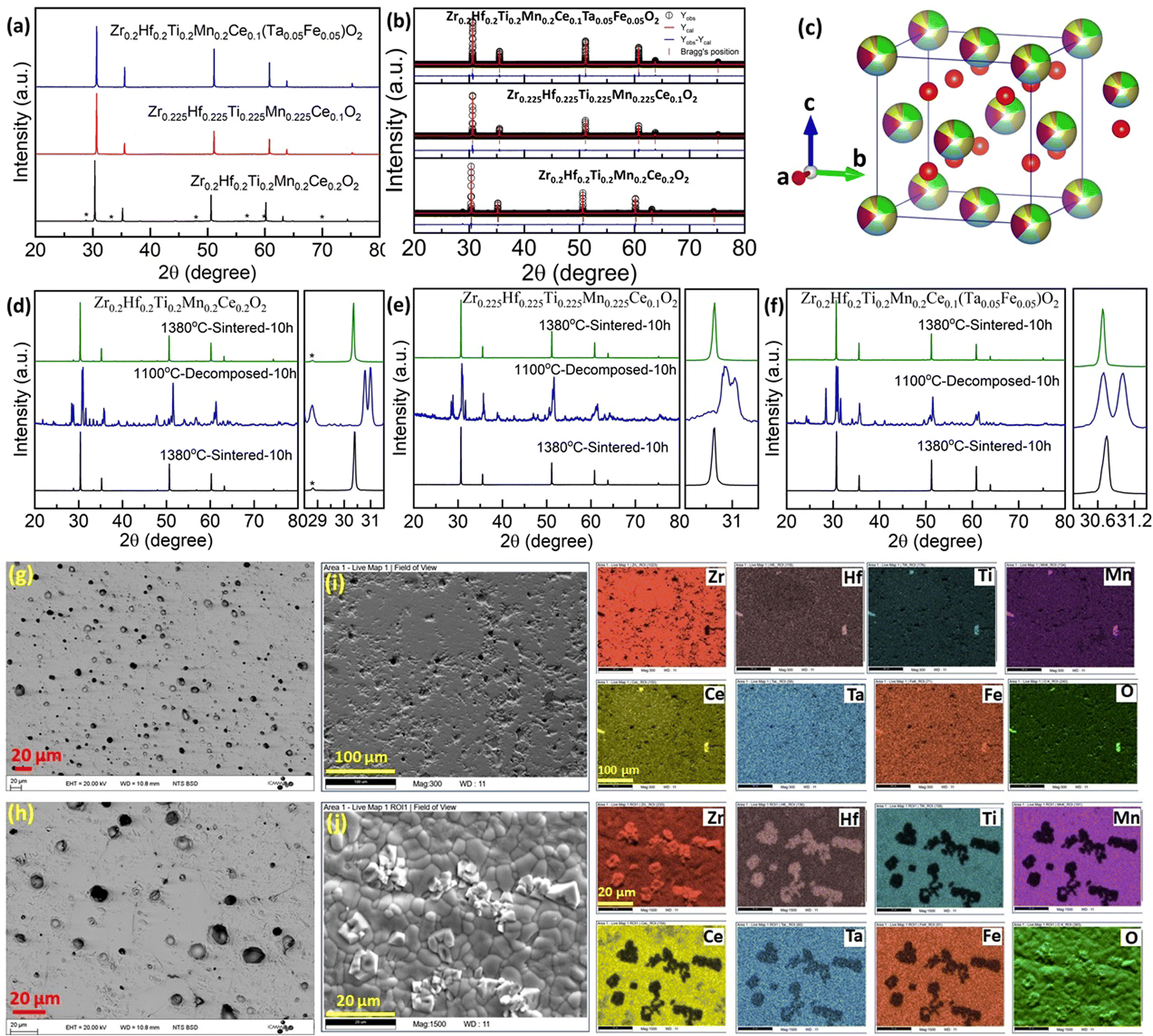 | ||
| Fig. 7 (a) X-ray diffraction pattern and (b) Rietveld refinement pattern for three single-phase fluorite oxides. The minor CeO2 peaks present in Zr0.2Hf0.2Ti0.2Mn0.2Ce0.2O2−δ, are marked with a star-shaped symbol (*) in (a). (c) The crystal structure of Zr0.2Hf0.2Ti0.2Mn0.2Ce0.1Ta0.05Fe0.05O2−δ is drawn using the refinement parameters employing Vesta software. (d–f) The cyclic heat treatment demonstrating entropy-stabilization of the fluorite is shown for all three samples. (g and h) Backscattered electron (BSE) image Zr0.2Hf0.2Ti0.2Mn0.2Ce0.1Ta0.05Fe0.05O2−δ, elemental mappings for Zr0.2Hf0.2Ti0.2Mn0.2Ce0.1Ta0.05Fe0.05O2−δ, (i) single-phase: sintered at 1380 °C followed by quenching and (j) decomposed sample: sintered at 1300 °C followed by slow cooling. | ||
The XRD pattern of these three samples is further analyzed using Rietveld refinement employing Fullprof software considering the Fmm space group. The refinement pattern for each phase is shown in Fig. 7(b). The lattice parameter for Zr0.2Hf0.2Ti0.2Mn0.2Ce0.2O2−δ is 5.095 Å, Zr0.225Hf0.225Ti0.225Mn0.225Ce0.1O2−δ is 5.052 Å, and Zr0.2Hf0.2Ti0.2Mn0.2Ce0.1Ta0.05Fe0.05O2−δ is 5.051 Å and is consistent with the change in the ionic radii of the cations for each composition.51 The crystal structure of Zr0.2Hf0.2Ti0.2Mn0.2Ce0.1Ta0.05Fe0.05O2−δ was drawn using Vesta software using the structural parameters (lattice parameter, atomic position, and occupancy) obtained from the refinement and is shown in Fig. 7(c). The entropy stabilization in these systems has been investigated through the cyclic heat treatment as shown in Fig. 7(d)–(f) for each composition. The reversible observation of the single-phase → multiphase → single-phase diffraction patterns of these samples with changing the sintering temperature below and above a critical temperature confirms that the thermodynamic stability of these samples is dominated by configurational entropy. The cyclic heat treatment at several temperatures in these systems is also shown in Fig. S6,† showing that this critical temperature is between 1300 °C and 1380 °C. As the use of a sintering temperature higher than 1380 °C leads to degradation of the pellets (due to the onset of pellet melting), it shows that the temperature window that can be used to obtain these new compositions is rather narrow.
Surface morphology and chemical homogeneity studies of the entropy-stabilized samples are carried out using the SEM-EDS technique. The microstructure shows a dense morphology of the samples sintered at 1380 °C having a relative density greater than 93%. The SEM images for Zr0.2Hf0.2Ti0.2Mn0.2Ce0.2O2−δ, and Zr0.225Hf0.225Ti0.225Mn0.225Ce0.1O2−δ are shown in Fig. S13.†Fig. 7(g) and (h) show the surface morphology for Zr0.2Hf0.2Ti0.2Mn0.2Ce0.1Ta0.05Fe0.05O2−δ in backscattered electron (BSE) mode. As mentioned earlier, the polishing of the pellets results in the removal of grains from the surface which can be seen in a higher magnification image (Fig. 7(h)). The sample without polishing looks quite dense, as shown in Fig. 7(j). The uniform surface morphology further supports the single-phase nature of the sample. EDS mapping shows compositional homogeneity as all the constituent elements (Zr, Hf, Ti, Mn, Ce, Ta, Fe, and O) were found to be uniformly distributed across the investigated area of the microstructure, as shown in Fig. 7(i) for single-phase Zr0.2Hf0.2Ti0.2Mn0.2Ce0.1Ta0.05Fe0.05O2−δ. Fig. 7(j) shows the surface morphology (BSE image) and corresponding elemental map for the Zr0.2Hf0.2Ti0.2Mn0.2Ce0.1Ta0.05Fe0.05O2−δ, sample decomposed at 1300 °C for 10 hours. The multiple phases and non-uniform distribution observed in the elemental map further confirm the decomposed nature of the sample.
X-ray photoelectron spectroscopy (XPS) studies are carried out in order to determine the charge states of each element in these entropy-stabilized systems. Full range spectra of the samples are shown in Fig. S9.† The core level spectra, displayed in Fig. 8(a)–(f), reveal the presence of Zr(4+), Hf(4+), Ti(4+), Mn(2+), Ce(4+), Ta(5+), and Fe(3+) (corresponding binding energies are shown in Table S2†) and are similar in all three samples. Interestingly Mn shows a 2+ valence state (see Fig. S10 and Table S4 of the ESI†), which is confirmed using the satellite peak characteristic of MnO (646.6 eV) in Fig. 8(e) and possibly accommodates oxygen vacancies present in the sample as shown in Fig. 8(g).52 This reduction of Mn from Mn4+ to Mn2+ increases the cationic radius of Mn from 0.53 Å (Mn4+) to 0.67LS Å, 0.83HS Å (Mn2+). This increase in the ionic radii is close to the average ionic radii of other elements. Fig. 8(h) shows a comparison of core-level spectra for Ce in Zr0.2Hf0.2Ti0.2Mn0.2Ce0.2O2−δ and Zr0.2Hf0.2Ti0.2Sn0.2Ce0.2O2. It is seen that Ce shows two distinct charge states in the Sn-containing samples (Table S3†); however it retains its Ce4+ charge state in Mn-containing samples. This is possibly the reason for the different structural behavior on the surface and bulk of Sn-containing samples. Therefore, this also indicates that Mn is an essential element to synthesize high-entropy fluorite oxides, as the reduction of Mn into a 2+ state enables Ce to remain in its +4 charge state.
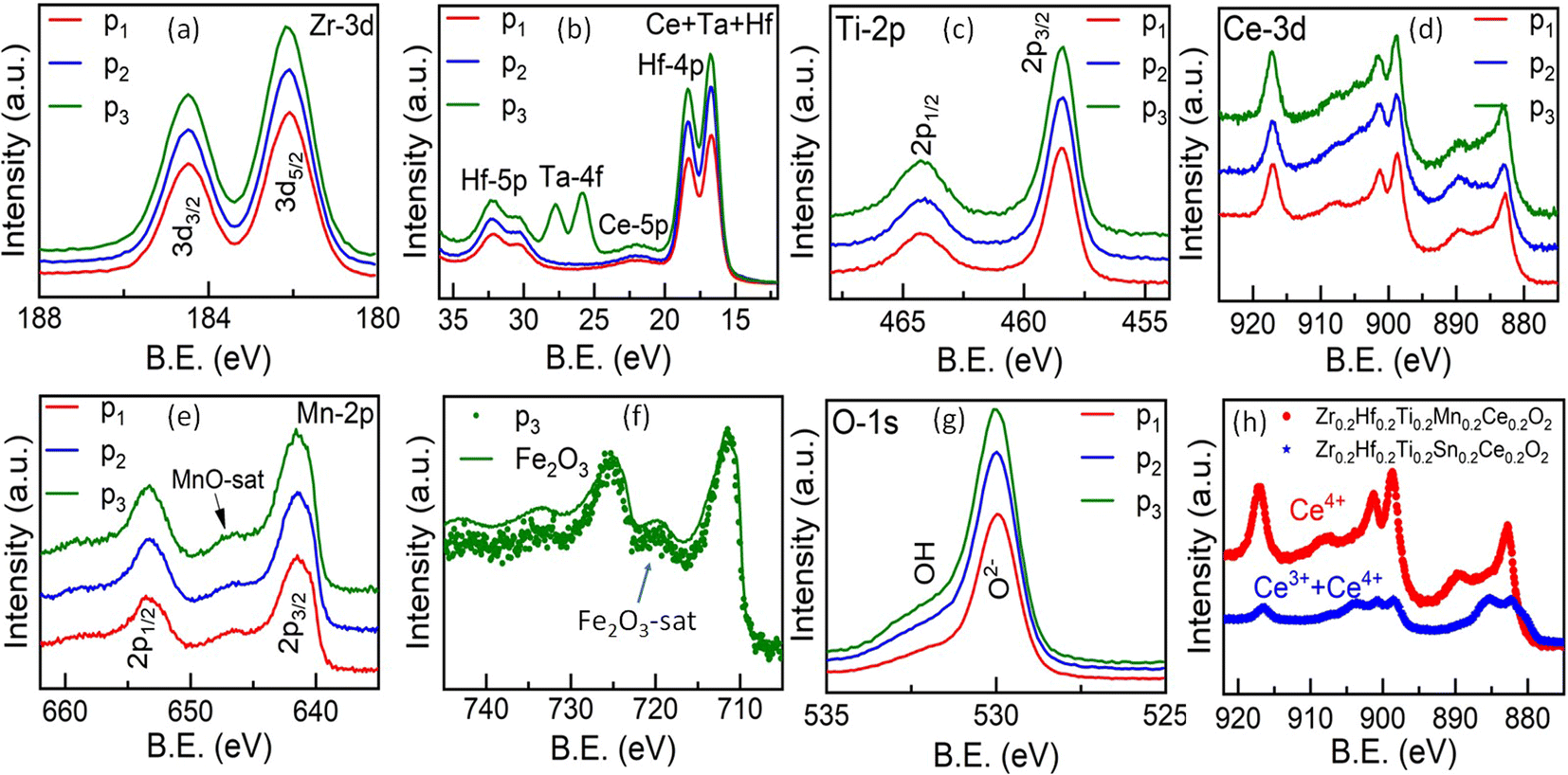 | ||
| Fig. 8 (a–g) Core-level X-ray photoelectron spectroscopy (XPS) spectra for the elements present in entropy-stabilized fluorite oxides. p1: Zr0.2Hf0.2Ti0.2Mn0.2Ce0.2O2−δ, p2: Zr0.225Hf0.225Ti0.225Mn0.225Ce0.1O2−δ and p3: Zr0.2Hf0.2Ti0.2Mn0.2Ce0.1Ta0.05Fe0.05O2−δ. (h) Comparison of Ce core-level XPS spectra of Zr0.2Hf0.2Ti0.2Mn0.2Ce0.2O2−δ and Zr0.2Hf0.2Ti0.2Sn0.2Ce0.2O2−δ. | ||
The Nyquist plots for all the samples are shown in Fig. S16† and the corresponding Bode plot consisting of the magnitude of the impedance |Z| and phase angle (ϕ) against frequency at different temperatures is shown in Fig. S17.† The measurements were performed under the same experimental conditions as mentioned above. The distribution of relaxation time (DRT) method has been used to determine the relaxation times contributing to the impedance spectrum.47,48 The DRT plots are obtained for all the samples to identify the number of processes involved in the transport process and are shown in Fig. S16(b), (d), and (f)† at different temperatures. It is noted that Zr0.2Hf0.2Ti0.2Mn0.2Ce0.2O2−δ, shows two clearly distinguishable processes across the temperature range studies and hence two ZARC models were used to fit the corresponding IS data. The two contributions might result from electronic contribution due to Zr0.2Hf0.2Ti0.2Mn0.2Ce0.2O2−δ and the minor CeO2 phase present in the sample. The second contribution may also originate from grain boundaries. Zr0.225Hf0.225Ti0.225Mn0.225Ce0.1O2−δ shows only one process and hence a single ZARC is used to estimate the transport parameters that are dominated by electronic conduction. A similar single-ZARC model is used to fit the IS data for Zr0.2Hf0.2Ti0.2Mn0.2Ce0.1Ta0.05Fe0.05O2−δ. In general, the DRT analysis provides the relaxation time and corresponding resistances (ionic, grain boundary or electronic) of the processes involved; however these resistances are not the actual resistance but rather represent their linear combination. Hence these values are used as a starting point to fit the IS data using the ZARC fit. The Nyquist plots are fitted using fit3Zarcs software38 using an appropriate equivalent circuit as shown in the respective insets of Fig. S16.† Fig. S16(a)† shows the Nyquist plot for Zr0.2Hf0.2Ti0.2Mn0.2Ce0.2O2−δ at four different temperatures, which are fitted using two ZARC elements (each consisting of a resistor (R) and constant phase element (Q) in parallel as shown in Fig. S16(a)†). It is observed that the impedance changes by one order of magnitude for a change in temperature from 298 K to 373 K. The resistivity values obtained from the fitting at 298 K are R1 = 1.81 × 10⁸ Ω cm & R2 = 5.18 × 10⁷ Ω cm and decrease to 7.41 × 10⁶ Ω cm & 2.75 × 10⁶ Ω cm respectively at 373 K, indicating thermally activated behavior with an activation energy of 0.34 eV and 0.42 eV respectively (Fig. S18(a) and (b)†). Zr0.225Hf0.225Ti0.225Mn0.225Ce0.1O2−δ was fitted using the proposed model as shown in Fig. S16(b).† The refined value of electrical resistivity at 298 K is 3.08 × 10⁸ Ω cm and it reduces to 1.44 × 10⁷ Ω cm at 373 K. The activation energy obtained from the linear fit of the Arrhenius plot is 0.42 eV (Fig. S16(c)†). The fitting of the Nyquist plot for Zr0.2Hf0.2Ti0.2Mn0.2Ce0.1Ta0.05Fe0.05O2−δ shows a change in the resistance from 3.37 × 10⁸ Ω cm at 298 K to 3.50 × 10⁶ Ω cm at 423 K with an activation energy of 0.4 eV (Fig. S18(d)†). The detailed transport parameters obtained from the fitting for each sample are shown in Tables S6–S8.†
The magnetic measurements (M–T) are carried out in zero-field cooling (ZFC) and field cooling (FC) modes over a temperature range of 2–350 K. It is seen that all three samples show similar magnetic behavior with a paramagnetic contribution over a wide temperature range (Fig. S19†). For all compositions, the Curie–Weiss fit of the 1/χ vs. T curve evidences antiferromagnetic interactions with a Curie–Weiss temperature (θcw) of −28 K, −30 K and −43 K respectively for Zr0.2Hf0.2Ti0.2Mn0.2Ce0.2O2−δ, Zr0.225Hf0.225Ti0.225Mn0.225Ce0.1O2−δ and Zr0.2Hf0.2Ti0.2Mn0.2Ce0.1Ta0.05Fe0.05O2−δ. Unexpectedly, the paramagnetic moment extracted from the Curie–Weiss fit leads to unrealistic values, much larger than those expected from free Mn2+ in high-spin configuration (even taking into account a possible moderate contribution from Ce3+ and Fe3+), from 8.48 μB in Zr0.2Hf0.2Ti0.2Mn0.2Ce0.2O2−δ to 8.81 μB in Zr0.2Hf0.2Ti0.2Mn0.2Ce0.1Ta0.05Fe0.05O2−δ and 8.94 μB in Zr0.225Hf0.225Ti0.225Mn0.225Ce0.1O2−δ. The M–H curve shown for these three samples at 2 K (Fig. S19†) shows an increase in magnetization with the magnetic field, here again to large values without reaching saturation even after ±5 T. At this stage, we do not have any plausible explanation to explain these unexpected values, which were obtained for all three samples.
Specific heat capacity as a function of temperature is shown in Fig. 9(a). As expected, the absolute value of the specific heat does not significantly differ from one composition to another. The room temperature value, close to 55 J mol−1 K−1, is very similar to the value reported for ZrO2 (ref. 53) and constitutes a signature of a large Debye temperature. The Debye temperatures obtained for the present samples are close to 550 K and is consistent with other reports for ZrO2 based systems.53 Also, Cpvs. T data show no anomaly in the whole temperature range. However, a plot of Cp/T vs. T2 at low temperature evidences a strong upturn below ∼14 K (Fig. 9(b)), characteristic of a Schottky anomaly. This Schottky anomaly could originate either from the presence of magnetic ions in the compounds, although no magnetic ordering is expected even at very low temperature due to the limited concentration of magnetic elements or to a quadrupole interaction linked to the presence of 20% to 22.5% of Hf in a distorted environment in the samples.54
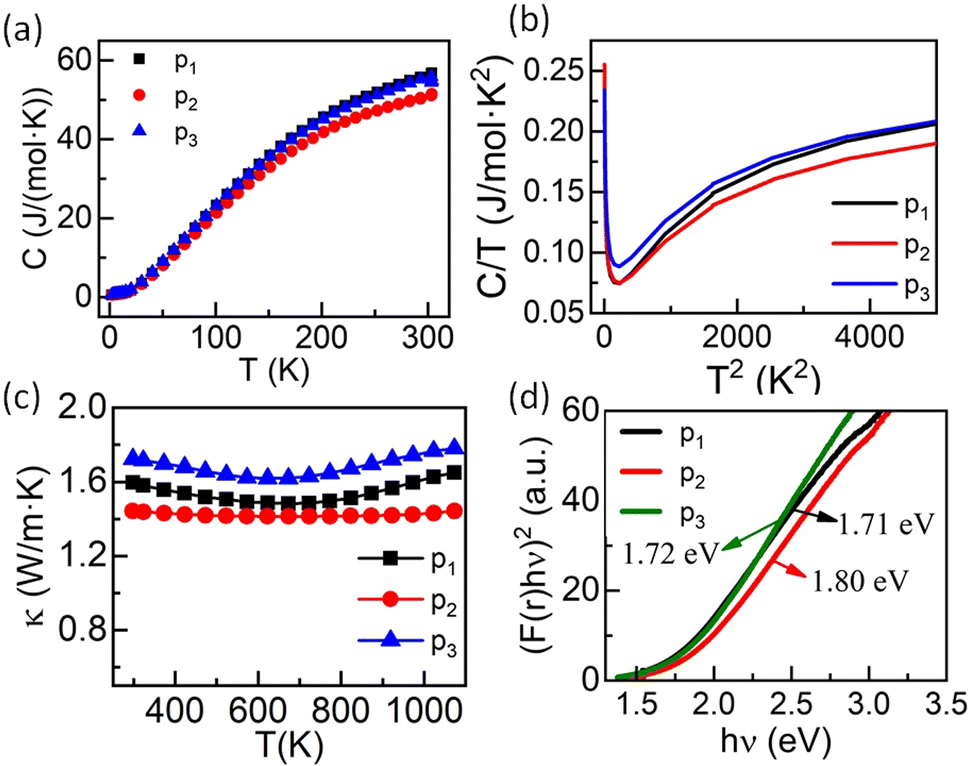 | ||
| Fig. 9 (a) Specific heat capacity (C) as a function of temperature, (b) C/T vs. T2, (c) temperature-dependent thermal conductivity (κ), and (d) optical band-gap calculated using UV-visible spectra of entropy-stabilized samples, where p1: Zr0.2Hf0.2Ti0.2Mn0.2Ce0.2O2−δ, p2: Zr0.225Hf0.225Ti0.225Mn0.225Ce0.1O2−δ and p3: Zr0.2Hf0.2Ti0.2Mn0.2Ce0.1Ta0.05Fe0.05O2−δ. | ||
The thermal conductivity (κ) studied over a wide range of temperatures (298 K to 1073 K) for these three entropy-stabilized fluorite oxides is shown in Fig. 9(c). The temperature-dependent thermal diffusivity (D) is shown in Fig. S20.† At first glance, κ seems to decrease slightly with an increase in temperature up to 650 K, above which it increases slowly. However, it should be noted that κ has been calculated using the specific heat capacity from the Dulong–Petit law. Since the Debye temperatures for these systems are close to ∼550 K, there is an overestimation of Cp, and thus κ up to circa 600 K. The thermal conductivity for all three samples is in the range of 1.42 W m−1 K−1 to 1.73 W m−1 K−1 at 298 K and is significantly lower than the thermal conductivity values of binary oxides.55 The random distribution of several cations with different masses and ionic radii results in enhanced scattering of phonons, which leads to a reduced lattice contribution to the thermal conductivity. As these materials possess poor electronic thermal conductivity (due to small electrical conductivity) at room temperature, the reduction in phonon thermal conductivity reduces the total thermal conductivity. The slight upward increase in κ at high temperatures may be due to the increase in electrical conductivity that enhances the electronic contribution to the thermal conductivity or due to photon thermal conductivity as reported recently56 that may also enhance the total thermal conductivity at higher temperatures. UV-visible spectroscopy in diffuse reflectance spectra (DRS) mode was performed at 300 K to find the optical band gap in these entropy-stabilized samples, as discussed above. The obtained UV-Vis spectra of all three samples are shown in Fig. S12.† The optical band gap (assuming a direct band gap) obtained for our three new entropy-stabilized samples is shown in Fig. 9(a). It is noted that the optical band gap for Zr0.2Hf0.2Ti0.2Ce0.2Sn0.2O2 is 3.05 eV (Fig. S11†) and it reduces to 1.72 eV for Zr0.2Hf0.2Ti0.2Mn0.2Ce0.1Ta0.05Fe0.05O2−δ. This reduction in band gap from near UV to visible could probably be linked to the introduction of 3d5 Mn2+ ions in these new entropy-stabilized samples, which could make them promising for photocatalytic application due to the absorption of wavelength in the visible region.
IV. Conclusion
This study presents a set of novel entropy-stabilized fluorite oxides using a combination of diffraction and spectroscopic techniques. First, we explore that entropy-stabilized fluorite oxide containing Sn as one of the elements viz. (Zr0.2Hf0.2Ti0.2Sn0.2Ce0.2)O2, (Zr0.2Hf0.2Ti0.2Sn0.2Mn0.2)O2−δ, and (Zr0.2Hf0.2Ti0.2Sn0.2Ce0.1Y0.1)O2−δ possess different crystal structures on the pellet (fluorite: Fmm) and in bulk/powder (fluorite: Fmm + orthorhombic: Pbcn). These observations are validated with structural and microstructural studies. The investigation of the origin of this peculiar behaviour leads to the design of a new entropy-stabilized fluorite oxide: (Zr0.2Hf0.2Ce0.2Sn0.2Mn0.2)O2−δ. This is followed by the synthesis of three new entropy-stabilized fluorite oxides: Zr0.2Hf0.2Ti0.2Mn0.2Ce0.2O2−δ, Zr0.225Hf0.225Ti0.225Mn0.225Ce0.1O2−δ, and Zr0.2Hf0.2Ti0.2Mn0.2Ce0.1Ta0.05Fe0.05O2−δ. X-ray diffraction pattern followed by Rietveld refinement depict a single-phase fluorite structure of the surface and bulk, which is further validated by scanning electron microscopy and energy dispersive X-ray spectroscopy analysis. The cyclic heat treatment reveals a reversible transition of multiple phases to single-phases below and above the transition temperature respectively and hence confirms that the thermodynamic stability is dominated by configurational entropy. The thermal conductivity (κ) in these samples is quite low (1.4–1.7 W m−1 K−1), which is explained by the enhanced phonon scattering in high-entropy samples due to high cationic disorder. Impedance spectroscopy measurements show a thermally activated behavior for all the entropy-stabilized samples with their activation energies ranging between 0.3 and 0.4 eV. These novel fluorite oxides have an optical band gap of 1.6–1.8 eV enabling them to be observed in visible spectra. Such a lowering of the band gap in these systems as compared to ZrO2, HfO2 or TiO2 based rutile oxides may be ascribed to the presence of high-spin 3d5 Mn2+ ions in these entropy-stabilized samples and could make them potential candidates for photocatalysis applications.
Author contributions
Ashutosh Kumar: conceptualization, investigation, formal analysis, writing – original draft, writing – review & editing, David Berardan: investigation, formal analysis, supervision, writing – review & editing, Francois Brisset: investigation, writing – review & editing, Diana Dragoe: investigation, formal analysis, writing – review & editing, Nita Dragoe: formal analysis, supervision, funding acquisition, project administration, writing – review & editing.Conflicts of interest
There are no conflicts to declare.Acknowledgements
This work was supported by the French Agence Nationale de la Recherche (ANR), through the project NEO (ANR 19-CE30-0030-01). The authors thank Eric Riviere for magnetic measurements.References
- B. L. Musicó, D. Gilbert, T. Z. Ward, K. Page, E. George, J. Yan, D. Mandrus and V. Keppens, APL Mater., 2020, 8, 040912 CrossRef.
- N. Dragoe and D. Bérardan, Science, 2019, 366, 573–574 CrossRef CAS PubMed.
- C. M. Rost, E. Sachet, T. Borman, A. Moballegh, E. C. Dickey, D. Hou, J. L. Jones, S. Curtarolo and J. P. Maria, Nat. Commun., 2015, 6, 8485 CrossRef CAS PubMed.
- B. Cantor, I. T. H. Chang, P. Knight and A. J. B. Vincent, Mater. Sci. Eng. A, 2004, 375–377, 213–218 CrossRef.
- J.-W. Yeh, S.-K. Chen, S.-J. Lin, J.-Y. Gan, T.-S. Chin, T.-T. Shun, C.-H. Tsau and S.-Y. Chang, Adv. Eng. Mater., 2004, 6, 299–303 CrossRef CAS.
- K. Chen, X. Pei, L. Tang, H. Cheng, Z. Li, C. Li, X. Zhang and L. An, J. Eur. Ceram. Soc., 2018, 38, 4161–4164 CrossRef CAS.
- R. Djenadic, A. Sarkar, O. Clemens, C. Loho, M. Botros, V. S. K. Chakravadhanula, C. Kübel, S. S. Bhattacharya, A. S. Gandhi and H. Hahn, Mater. Res. Lett., 2017, 5, 102–109 CrossRef CAS.
- A. Mao, H. X. Xie, H. Z. Xiang, Z. G. Zhang, H. Zhang and S. Ran, J. Magn. Magn. Mater., 2020, 503, 166594 CrossRef CAS.
- H. Chen, N. Qiu, B. Wu, Z. Yang, S. Sun and Y. Wang, RSC Adv., 2020, 10, 9736–9744 RSC.
- B. Musicó, Q. Wright, T. Z. Ward, A. Grutter, E. Arenholz, D. Gilbert, D. Mandrus and V. Keppens, Phys. Rev. Mater., 2019, 3, 104416 CrossRef.
- A. Sarkar, C. Loho, L. Velasco, T. Thomas, S. S. Bhattacharya, H. Hahn and R. Djenadic, Dalton Trans., 2017, 46, 12167–12176 RSC.
- S. Jiang, T. Hu, J. Gild, N. Zhou, J. Nie, M. Qin, T. Harrington, K. Vecchio and J. Luo, Scr. Mater., 2018, 142, 116–120 CrossRef CAS.
- A. Kirnbauer, C. Spadt, C. M. Koller, S. Kolozsvári and P. H. Mayrhofer, Vacuum, 2019, 168, 108850 CrossRef CAS.
- G. Karthick, L. Raman and B. S. Murty, J. Mater. Sci. Technol., 2021, 82, 214–226 CrossRef CAS.
- Z. Teng, L. Zhu, Y. Tan, S. Zeng, Y. Xia, Y. Wang and H. Zhang, J. Eur. Ceram. Soc., 2020, 40, 1639–1643 CrossRef CAS.
- F. Vayer, C. Decorse, D. Bérardan and N. Dragoe, J. Alloys Compd., 2021, 883, 160773 CrossRef CAS.
- D. Bérardan, S. Franger, A. K. Meena and N. Dragoe, J. Mater. Chem. A, 2016, 4, 9536–9541 RSC.
- F. Li, L. Zhou, J. X. Liu, Y. Liang and G. J. Zhang, J. Adv. Ceram., 2019, 8, 576–582 CrossRef CAS.
- A. Kumar, D. Dragoe, D. Berardan and N. Dragoe, J. Materiomics, 2023, 9, 191–196 CrossRef.
- A. Kumar, D. Bérardan, D. Dragoe, E. Riviere, T. Takayama, H. Takagi and N. Dragoe, Mater. Today Phys., 2023, 32, 101026 CrossRef CAS.
- D. Bérardan, S. Franger, D. Dragoe, A. K. Meena and N. Dragoe, Phys. Status Solidi RRL, 2016, 10, 328–333 CrossRef.
- M. Gazda, T. Miruszewski, D. Jaworski, A. Mielewczyk-Gryń, W. Skubida, S. Wachowski, P. Winiarz, K. Dzierzgowski, M. Łapiński, I. Szpunar and E. Dzik, ACS Mater. Lett., 2020, 2, 1315–1321 CrossRef CAS.
- P. Edalati, Q. Wang, H. Razavi-Khosroshahi, M. Fuji, T. Ishihara and K. Edalati, J. Mater. Chem. A, 2020, 8, 3814–3821 RSC.
- Y. Sun and S. Dai, Sci. Adv., 2021, 7, eabg1600 CrossRef CAS PubMed.
- A. Sarkar, B. Breitung and H. Hahn, Scr. Mater., 2020, 187, 43–48 CrossRef CAS.
- C. Oses, C. Toher and S. Curtarolo, Nat. Rev. Mater., 2020, 5, 295–309 CrossRef CAS.
- B. S. Murty, J.-W. Yeh and S. Ranganathan, High-Entropy Alloys, Elsevier, 1st edn, 2014 Search PubMed.
- A. Sarkar, B. Eggert, L. Velasco, X. Mu, J. Lill, K. Ollefs, S. S. Bhattacharya, H. Wende, R. Kruk, R. A. Brand and H. Hahn, APL Mater., 2020, 8, 051111 CrossRef CAS.
- A. Sarkar, B. Eggert, R. Witte, J. Lill, L. Velasco, Q. Wang, J. Sonar, K. Ollefs, S. S. Bhattacharya, R. A. Brand, H. Wende, F. M. F. de Groot, O. Clemens, H. Hahn and R. Kruk, Acta Mater., 2022, 226, 117581 CrossRef CAS.
- A. Sarkar, R. Djenadic, D. Wang, C. Hein, R. Kautenburger, O. Clemens and H. Hahn, J. Eur. Ceram. Soc., 2018, 38, 2318–2327 CrossRef CAS.
- S. J. McCormack and A. Navrotsky, Acta Mater., 2021, 202, 1–21 CrossRef CAS.
- J. Gild, M. Samiee, J. L. Braun, T. Harrington, H. Vega, P. E. Hopkins, K. Vecchio and J. Luo, J. Eur. Ceram. Soc., 2018, 38, 3578–3584 CrossRef CAS.
- Y. Wen and Y. Liu, Ceram. Int., 2022, 48, 2546–2554 CrossRef CAS.
- Y. H. Ding, L. Liu, R. Z. Guo, L. Li and X. M. Chen, J. Am. Ceram. Soc., 2022, 105, 6710–6717 CrossRef CAS.
- J. He, Z. Li and Y. Liu, Mater. Lett., 2021, 299, 130082 CrossRef CAS.
- M. V. Kante, H. Hahn, S. S. Bhattacharya and L. Velasco, J. Alloys Compd., 2023, 947, 169430 CrossRef CAS.
- G. Chen, C. Li, H. Jia, H. Li, S. Li, B. Gong, L. An and K. Chen, J. Eur. Ceram. Soc., 2023, 43, 2586–2592 CrossRef CAS.
- N. Dragoe, 2021, 10.13140/RG.2.2.17133.31205, https://www.researchgate.net/publication/352355437_fit_3_zarcs.
- A. Pfau and K. D. Schierbaum, Surf. Sci., 1994, 321, 71–80 CrossRef CAS.
- E. Paparazzo, Mater. Res. Bull., 2011, 46, 323–326 CrossRef CAS.
- L. Qiu, F. Liu, L. Zhao, Y. Ma and J. Yao, Appl. Surf. Sci., 2006, 252, 4931–4935 CrossRef CAS.
- M. Romeo, K. Bak, J. el Fallah, F. le Normand and L. Hilaire, Surf. Interface Anal., 1993, 20, 508–512 CrossRef CAS.
- H. M. Rietveld, J. Appl. Crystallogr., 1969, 2, 65–71 CrossRef CAS.
- K. Momma and F. Izumi, J. Appl. Crystallogr., 2011, 44, 1272–1276 CrossRef CAS.
- J. Liu and F. Ciucci, J. Electrochem. Soc., 2020, 167, 026506 CrossRef CAS.
- F. Ciucci, Curr. Opin. Electrochem., 2019, 13, 132–139 CrossRef CAS.
- M. Steinhauer, S. Risse, N. Wagner and K. A. Friedrich, Electrochim. Acta, 2017, 228, 652–658 CrossRef CAS.
- J. P. Schmidt, P. Berg, M. Schönleber, A. Weber and E. Ivers-Tiffée, J. Power Sources, 2013, 221, 70–77 CrossRef CAS.
- P. Makuła, M. Pacia and W. Macyk, J. Phys. Chem. Lett., 2018, 9, 6814–6817 CrossRef PubMed.
- L. Spiridigliozzi, C. Ferone, R. Cioffi and G. Dell'Agli, Acta Mater., 2021, 202, 181–189 CrossRef CAS.
- R. D. Shannon, Acta Crystallogr., Sect. A, 1976, 32, 751–767 CrossRef.
- J. L. Junta and M. F. Hochella, Geochim. Cosmochim. Acta, 1994, 58, 4985–4999 CrossRef CAS.
- C. Degueldre, P. Tissot, H. Lartigue and M. Pouchon, Thermochim. Acta, 2003, 403, 267–273 CrossRef CAS.
- W. N. Lawless, Phys. Rev. B: Condens. Matter Mater. Phys., 1980, 21, 585–588 CrossRef CAS.
- K. Suzuki, M. Kato, T. Sunaoshi, H. Uno, U. Carvajal-Nunez, A. T. Nelson and K. J. McClellan, J. Am. Ceram. Soc., 2019, 102, 1994–2008 CrossRef CAS.
- Y. Zhang, M. Xie, Z. Wang, X. Song, R. Mu, F. Zhou, J. Bao, J. Gao and W. Pan, Scr. Mater., 2023, 228, 115328 CrossRef CAS.
Footnote |
| † Electronic supplementary information (ESI) available. See DOI: https://doi.org/10.1039/d3ta02124f |
| This journal is © The Royal Society of Chemistry 2023 |