
Regulating zinc deposition behaviors by using a functional PANI modification layer on a separator for high performance aqueous zinc-ion batteries†
Fangfang
Wu
a,
Fukai
Du
a,
Pengchao
Ruan
b,
Gangfeng
Cai
a,
Ye
Chen
a,
Xinyu
Yin
a,
Lu
Ma
a,
Ruilian
Yin
c,
Wenhui
Shi
d,
Wenxian
Liu
a,
Jiang
Zhou
 b and
Xiehong
Cao
*a
b and
Xiehong
Cao
*a
aCollege of Materials Science and Engineering, Zhejiang University of Technology, 18 Chaowang Road, Hangzhou 310014, P. R. China. E-mail: gcscaoxh@zjut.edu.cn
bCollege of Materials Science and Engineering, Central South University, 932 South Lushan Road, Changsha 410083, P. R. China
cCollege of Chemical Engineering, Zhejiang University of Technology, 18 Chaowang Road, Hangzhou 310014, Zhejiang, P. R. China
dCenter for Membrane and Water Science & Technology, Zhejiang University of Technology, 18 Chaowang Road, Hangzhou 310014, P. R. China
First published on 25th April 2023
Abstract
Aqueous zinc-ion batteries (AZIBs) are promising energy storage devices due to their high safety, abundant zinc reserves, high theoretical capacity and low redox potential. Glass fiber (GF) has been widely used as a separator in AZIBs; however, the strong affinity to zinc ions of GF easily induces the growth of zinc dendrites towards the separator and results in a short circuit of the battery. Herein, we propose a new strategy for regulating zinc deposition behaviors by in situ polyaniline (PANI) modification on a commercial GF separator (GF/PANI). The theoretical and experimental results indicate that a PANI modification layer weakens zincophilicity force, homogenizes the surface electric field distribution and induces uniform plating/stripping of zinc ions, and thus, the reversibility of the zinc anode is significantly improved. Typically, a Zn‖Zn symmetric battery with a GF/PANI-600 separator can sustain a longer cycle up to 3000 h at 1.0 mA cm−2 with 1.0 mA h cm−2, far exceeding than that with a GF separator (70 h). Additionally, a Zn‖MnO2 full battery with a GF/PANI-600 separator also delivers a higher capacity retention rate of 89.5% after 300 cycles at 0.5 A g−1 (50.7% that of the Zn|GF|MnO2 battery). This work provides a new insight into the design of durable AZIBs from the viewpoint of the modification of the separator.
Introduction
Electrochemical energy storage technologies (such as Li, Na, and Zn-ion batteries) have been considered the key to realize the target of carbon neutrality around the world. Among various energy storage technologies, aqueous zinc-ion batteries (AZIBs) as a promising alternative to Li-ion batteries have advanced rapidly due to their advantages of high safety, low cost, high anodic theoretical capacity (820 mA h g−1) and low anodic redox potential (−0.76 V versus the standard hydrogen electrode).1–4 However, the practical application of AZIBs is limited by the following issues, i.e., the undesirable Coulombic efficiency (CE) and poor cycle life caused by the dendrite growth, and side reactions (hydrogen evolution reaction (HER) and corrosion reaction) of a Zn metal anode.5,6 In the aqueous electrolyte, the distribution of the electrical field near the commercial Zn foil surface is uneven, which easily leads to the uncontrolled growth of Zn dendrites at protuberance sites because of the “tip effect” during the zinc deposition process. In addition, the corrosion of Zn metal and the competing HER in an aqueous electrolyte are inevitable, which also facilitate the uneven distribution of the electrical field and irregular dendrite growth.7,8 These issues are determined by the interface of the electrode/electrolyte and electrolyte/separator.In view of the above problems, various strategies have been put forward to improve the reversibility of Zn anodes, such as the modification of a Zn surface by inducting a protective layer,9–11 the rational design of Zn anodes,12,13 and the optimization of electrolytes.14–16 Currently, some significant progress in the preparation of novel Zn anodes or electrolyte regulation has been made. A separator, as an inactive component in the batteries, not only avoids the direct physical contact of the cathode/anode, but also allows ion transportation. Up to now, the study on separators is far from enough. Glass fiber (GF) has been widely used in AZIBs due to the merits of its porosity, high ionic conductivity and delightful electrolyte wettability.17,18 Unfortunately, GF displays a strong affinity to zinc ions on the electrolyte/separator interface. Thus, GF tends to induce the growth of zinc dendrites towards the separator during the plating process, which punctures the separator and results in a short circuit of the battery.19,20 Moreover, the ion flux is hard to regulate in the absence of a modification layer.17,21 Therefore, separator engineering is one of the keys to solve the above issues. Wang et al. introduced an intermediate membrane of cellulose paper between the anode and the separator, the affinity between zinc ions and the separator can be weakened, and interlayer engineering can induce the lateral growth of zinc and mitigate the accumulation of zinc ions and by-products at the zinc negative electrode.22 Furthermore, one feasible solution is to prepare a new separator to replace the GF separator, such as cellulose film (CF),23 Nafion,24 or polyacrylonitrile (PAN) nanofiber separators.25 However, the preparation process of the intermediate membrane and new separator is complicated. Modification of the separator is also an effective strategy, such as modifying the GF by using MXenes and vertical graphene; the excellent conductivity of the modified layer can homogenize the interfacial electric field and homogenize the zinc ion flux.18,26 Polyaniline (PANI) as a typical conductive polymer, shows the characteristics of high conductivity, easy fabrication and good environmental stability.27,28 The long π-electron conjugated structure in PANI contributes the excellent electron and ion migration rates. The abundant functional groups of PANI provide N active sites for Zn. The PANI modification layer possesses the potential for homogenizing electric field distribution and guiding the growth of zinc dendrites. However, a study on separator engineering based on PANI modification has not been reported in AZIBs.
Herein, we construct a multifunctional separator through in situ polymerization of aniline monomers on one side of the GF separator (denoted as GF/PANI) to homogenize electric field distribution and guide the deposition of zinc ions, thus improving the reversibility of Zn anodes. Benefitting from the PANI modification layer, the GF/PANI separator modulates the flux of zinc ions, and homogenizes the interfacial electric field distribution. Density functional theory (DFT) calculation results indicate that the PANI modification layer weakens the affinity to zinc on the interface of the separator, which contributes to uniform zinc deposition. And the PANI modification layer prevents the vertical deposition of zinc from gathering into dendrites to pierce the separator. The Zn‖Zn symmetric battery using a GF/PANI separator cycles for up to 3000 h at 1.0 mA cm−2 with an area capacity of 1.0 mA h cm−2, which is approaching 43-fold that of a battery using a GF separator. Similarly, a GF/PANI separator in the Zn‖MnO2 full battery also contributes a higher specific capacity and stability than the pristine GF separator.
Experimental
Materials
Zinc sulfate heptahydrate (ZnSO4·7H2O, AR), manganese sulfate monohydrate (MnSO4·H2O, AR), 1-methyl-2-pyrrolidinone (NMP, 99%) and sulfuric acid (H2SO4, 98%) were purchased from J&KCHEMICA (China). Ammonium persulfate ((NH4)2S2O8, ≥98%) was purchased from Xilong Chemical Co., Ltd (China). Hydrochloric acid (HCl, 36–38%) was purchased from Kunshan Jincheng Reagent Co., Ltd (China). Aniline (C6H7N, ≥99.9%) was purchased from Shanghai Maclean Biochemical Technology Co., Ltd (China). Potassium permanganate (KMnO4, AR) was purchased from Shanghai Vokai Biotechnology Co., Ltd (China). Zinc-foil (0.05 mm thickness) and copper-foil (0.02 mm thickness) were purchased from Yi Zhongtian New Material Co., Ltd (China) and Haoxuan Metal Material Co., Ltd (China). The glass fiber separator is Whatman. Carbon paper was purchased from Suzhou Sinero Technology Co., Ltd (China).Preparation of the GF/PANI separator
First, 3.2 mmol (NH4)2S2O8 (0.73 g) was dissolved in 20 mL deionized water, and then 2 mL HCl (12 mol L−1) was dropped in the above solution to form solution A. Then, 2 mL HCl and different volumes of C6H7N (300, 450, 600 and 750 μL) were dispersed in 20 mL deionized water to form solution B. After that, the GF separator (one side of GF was covered) is completely wetted in solution B in an ice-water bath. Subsequently, solution A was added to solution B, and allowed to stand for 30 min. Finally, the separator was cleaned with deionized water and ethanol, and then dried in a vacuum oven at 60 °C for 24 h.Preparation of MnO2
First of all, 2 mL H2SO4 (0.5 mol L−1) was dispersed in 60 mL deionized water, and then 3 mmol MnSO4·H2O was dissolved in it, and the mixture was then agitated magnetically for 10 min. Then, 20 mL KMnO4 (0.1 mol L−1) solution was added to the above solution and magnetically stirred for 1 h. Finally, the above mixture was placed in a 100 mL Teflon-lined autoclave and heated at 120 °C for 12 h, and the solid product was collected by centrifugation and washed with deionized water. The product was dried at 60 °C for 12 h.29Characterization
The phase composition of the samples was characterized by X-ray diffraction (XRD, PANAlytical X'Pert PRO) with Cu Kα radiation, λ = 1.54056 Å. X-ray photoelectron spectroscopy (XPS, Shimadzu Co., Ltd Hongkong) with a Kratos Axis Ultra-DLD system was carried out. Raman spectroscopy was performed by using a LabRAM HR Evolution, Horiba with a 532 nm laser focused through a 100× objective lens. Fourier transform infrared spectroscopy (FTIR) was performed by using a Thermo Scientific Nicolet iS20. Surface morphology of the samples was characterized by field-emission scanning electron microscopy (FE-SEM, HITACHI Regulus 8100) at an acceleration voltage of 20 kV. The in situ microscope images for the Zn plating/stripping process were recorded by using a commercial optical microscope (BM-1000). 3D confocal images of the Zn anodes were collected by using a laser confocal scanning microscope (Zeiss LSM 700).Electrochemical measurement
Zn‖Zn, Zn‖Cu and stainless steel‖stainless steel batteries were assembled by using CR2032 coin-type batteries using GF (GE-Whatman) and GF/PANI as separators, and 2 M ZnSO4 as the electrolyte. Cyclic voltammetry (CV), linear sweep voltammetry (LSV), i–t, and electrochemical impedance spectroscopy (EIS) measurements were tested on an electrochemistry workstation (CHI 650E, China). Galvanostatic charge–discharge cycling tests were conducted on a Neware battery test system (Neware CT-4008T). The MnO2 electrode was prepared by mixing MnO2, carbon black and PVDF with a mass ratio of 8![[thin space (1/6-em)]](https://www.rsc.org/images/entities/char_2009.gif) :1:1, and using 1-methyl-2-pyrrolidinon (NMP) as the solvent. The above slurry was coated on the carbon paper and dried at 80 °C overnight in a vacuum oven. The mass loading of MnO2 is about 1–1.2 mg cm−2. In addition, 2 M ZnSO4 + 0.1 M MnSO4 was used as the electrolyte for Zn‖MnO2 full batteries.
:1:1, and using 1-methyl-2-pyrrolidinon (NMP) as the solvent. The above slurry was coated on the carbon paper and dried at 80 °C overnight in a vacuum oven. The mass loading of MnO2 is about 1–1.2 mg cm−2. In addition, 2 M ZnSO4 + 0.1 M MnSO4 was used as the electrolyte for Zn‖MnO2 full batteries.
Density functional theory (DFT) calculations
DFT calculations were performed using the Vienna ab initio simulation package's projector-augmented wave (PAW) approach (VASP).30,31 To characterize the exchange–correlation interaction, a generalized gradient approximation (GGA) of the Perdew–Burke–Ernzerhof (PBE) functional was used.32 All computations used a 400 eV energy cutoff and a gamma-centered 2 × 2 × 1 mesh. The adsorption energy between a zinc atom and SiO2 and polyaniline (PANI) was calculated for a vacuum layer of 10 Å. The forces and total energy on all atoms converged to less than 0.05 eV Å−1 and 1 × 10⁻⁷ eV, respectively. In order to evaluate the interaction between Zn atoms and the separator, the adsorption energy (Ea) was calculated as follows:| Ea = Etotal − EZn − Esurface |
Results and discussion
The GF/PANI composite separators were prepared by in situ polymerization of aniline monomers on one side of the GF separator in an acidic medium at low temperature. The preparation process of GF/PANI is schematically illustrated in Fig. S1.† After PANI coating, the colour of the GF separator was changed from white to green (Fig. S2†). Scanning electron microscope (SEM) characterization indicates that the pristine GF displays a smooth surface (Fig. 1a), while the surface of the GF/PANI separator possesses a rough surface (Fig. 1b). In the enlarged view, the irregular particles are distributed on the GF surface (inset of Fig. 1b), suggesting the successful modification of PANI. We also investigated the effect of the concentrations of aniline monomers on the final PANI layer (Fig. S3†). When the volumes of aniline monomers are 300 and 450 μL (denoted as GF/PANI-300 and GF/PANI-450), an incompletely covered surface of the separator is observed as shown in Fig. S3a and b.† As the volume of aniline monomers is further increased to 750 μL (denoted as GF/PANI-750), excess PANI particles are observed on GF, which fills the interspace of the GF separator and blocks the transport channel of zinc ions (Fig. S3c†). In comparison, a uniformly modified GF surface is obtained when the added volume of aniline monomers is 600 μL (denoted as GF/PANI-600). As expected, the corresponding elemental mapping profiles of GF/PANI-600 also illustrate the uniform distribution of C (red), N (green), and O (blue), indicating the uniform coating of the PANI modification layer (Fig. 1c).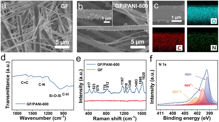 | ||
| Fig. 1 Structural characterization of the GF/PANI-600 composite separators. SEM images of (a) pristine GF and (b) GF/PANI-600. (c) Elemental mapping images, (d) FTIR spectrum, (e) Raman spectrum, and (f) N 1s XPS spectrum of GF/PANI-600. | ||
Fourier transform infrared spectroscopic (FTIR) measurement was carried out to examine the bond formation of GF/PANI. Fig. 1d shows the FTIR spectrum of GF/PANI-600 separators, and the peak located at 954 cm−1 is assigned to Si–O–Si,20,33 The peaks located at 1560 and 1480 cm−1 are attributed to the stretching vibrations of C![[double bond, length as m-dash]](https://www.rsc.org/images/entities/char_e001.gif) C in the quinone structure and the benzene structure, respectively.34 And the peaks located at 1300 and 1243 cm−1 are assigned to the C–N stretching vibration. The peak located at 793 cm−1 originates from the bending vibration of the C–H bond of the p-substituted benzene ring.35,36 The GF/PANI separators obtained with different amounts of aniline monomers display similar FTIR spectra (Fig. S4†). Then, Raman spectroscopic characterization was performed, and Fig. 1e shows the Raman spectra of GF and GF/PANI-600. The vibration modes located at 417 and 523 cm−1 are assigned to out-of-plane ring deformations.37 And the peaks located at 579, 778 and 812 cm−1 originate from the phenoxazine-type units, and quinonoid ring and benzene ring deformation, respectively.37 The C–H bending vibration in the benzene ring, C–N stretching vibration of the quinonoid ring and C–N+ stretching vibration are observed at 1167, 1218 and 1348 cm−1, respectively.37,38 Moreover, the peaks located at 1493, 1595 and 1620 cm−1 are attributed to the stretching vibration of CN, stretching vibration of C–C and stretching vibration of CC in the quinoid ring, respectively.39 In contrast, these vibration modes are not observed on the pristine GF separator. The high resolution XPS spectrum of N 1s of GF/PANI-600 (Fig. 1f) is divided into three peaks located at 399.6, 400.7 and 402.4 eV, which are assigned to –NH–, –NH+– and –NH+ , respectively.40,41 All the above results confirm the successful and uniform coating of the PANI layer on the GF separator.
C in the quinone structure and the benzene structure, respectively.34 And the peaks located at 1300 and 1243 cm−1 are assigned to the C–N stretching vibration. The peak located at 793 cm−1 originates from the bending vibration of the C–H bond of the p-substituted benzene ring.35,36 The GF/PANI separators obtained with different amounts of aniline monomers display similar FTIR spectra (Fig. S4†). Then, Raman spectroscopic characterization was performed, and Fig. 1e shows the Raman spectra of GF and GF/PANI-600. The vibration modes located at 417 and 523 cm−1 are assigned to out-of-plane ring deformations.37 And the peaks located at 579, 778 and 812 cm−1 originate from the phenoxazine-type units, and quinonoid ring and benzene ring deformation, respectively.37 The C–H bending vibration in the benzene ring, C–N stretching vibration of the quinonoid ring and C–N+ stretching vibration are observed at 1167, 1218 and 1348 cm−1, respectively.37,38 Moreover, the peaks located at 1493, 1595 and 1620 cm−1 are attributed to the stretching vibration of CN, stretching vibration of C–C and stretching vibration of CC in the quinoid ring, respectively.39 In contrast, these vibration modes are not observed on the pristine GF separator. The high resolution XPS spectrum of N 1s of GF/PANI-600 (Fig. 1f) is divided into three peaks located at 399.6, 400.7 and 402.4 eV, which are assigned to –NH–, –NH+– and –NH+ , respectively.40,41 All the above results confirm the successful and uniform coating of the PANI layer on the GF separator.
In order to highlight the advantage of a PANI modified GF separator in AZIBs, Zn plating and stripping properties were investigated in 2.0 M ZnSO4 electrolyte by assembling 2032-type batteries with GF/PANI and GF separators. As shown in Fig. 2a, a Zn‖Zn symmetric battery with a GF separator (Zn|GF|Zn) can only remain stable within 70 h at 1.0 mA cm−2 with 1.0 mA h cm−2. Then the voltage suddenly drops, which may be caused by a short circuit due to the dendrite growth of the zinc anode. When a PANI modified GF separator is used, the cycling stability of Zn‖Zn symmetric batteries is all improved. Typically, a Zn‖Zn symmetric battery using a GF/PANI-600 separator (Zn|GF/PANI-600|Zn) shows greatly enhanced stable cycling for 3000 h, approximately 43-fold higher than that of Zn|GF|Zn. For GF/PANI-300, 450 and 750 separators, the batteries can sustain stable cycling over 120, 250 and 448 h, respectively. Obviously, the GF/PANI-600 separator is optimal, which may be due to the uniform PANI coating. When cycled at 0.5 mA cm−2 with 0.5 mA h cm−2, the Zn‖Zn battery equipped with a GF/PANI-600 separator maintains a stable cycling performance over 2700 h, which is much better than that of Zn‖Zn with a GF separator (failed after 86 h, Fig. 2b). The Zn plating/stripping performance was further investigated at 2.0 mA cm−2 with 1.0 mA h cm−2 and 2.0 mA cm−2 with 2.0 mA h cm−2 by using a Zn‖Zn symmetric battery (Fig. S5†). Similarly, the superiority of Zn‖Zn symmetric batteries with GF/PANI-600 separators in cycling life are well maintained (1700 h at 2.0 mA cm−2 with 1.0 mA h cm−2 and 1600 h at 2.0 mA cm−2 with 2.0 mA h cm−2), which is superior to those of the batteries using pristine GF separators. Moreover, the rate performance of Zn‖Zn symmetric batteries was also assessed. Fig. 2c shows the comparison of rate performance with GF/PANI-600 and pristine GF separators at different current densities with a capacity of 1.0 mA h cm−2. The Zn|GF/PANI-600|Zn battery delivers a stable cycling at 0.5, 1, 2, 3, 4, and5 mA cm−2. Specifically, the voltages are recovered when the current densities are returned. It still maintains stable cycling for over 700 h when the current density is recovered to 0.5 mA cm−2. In contrast, the Zn|GF|Zn battery fails after 76 h at 4.0 mA cm−2 with a sharp fluctuation. Notably, the Zn‖Zn symmetric battery with a GF/PANI-600 separator not only displays a longer life span than a Zn‖Zn symmetric battery with a GF separator, but is also much superior to those in many recently reported related studies (Fig. S6 and Table S1†).
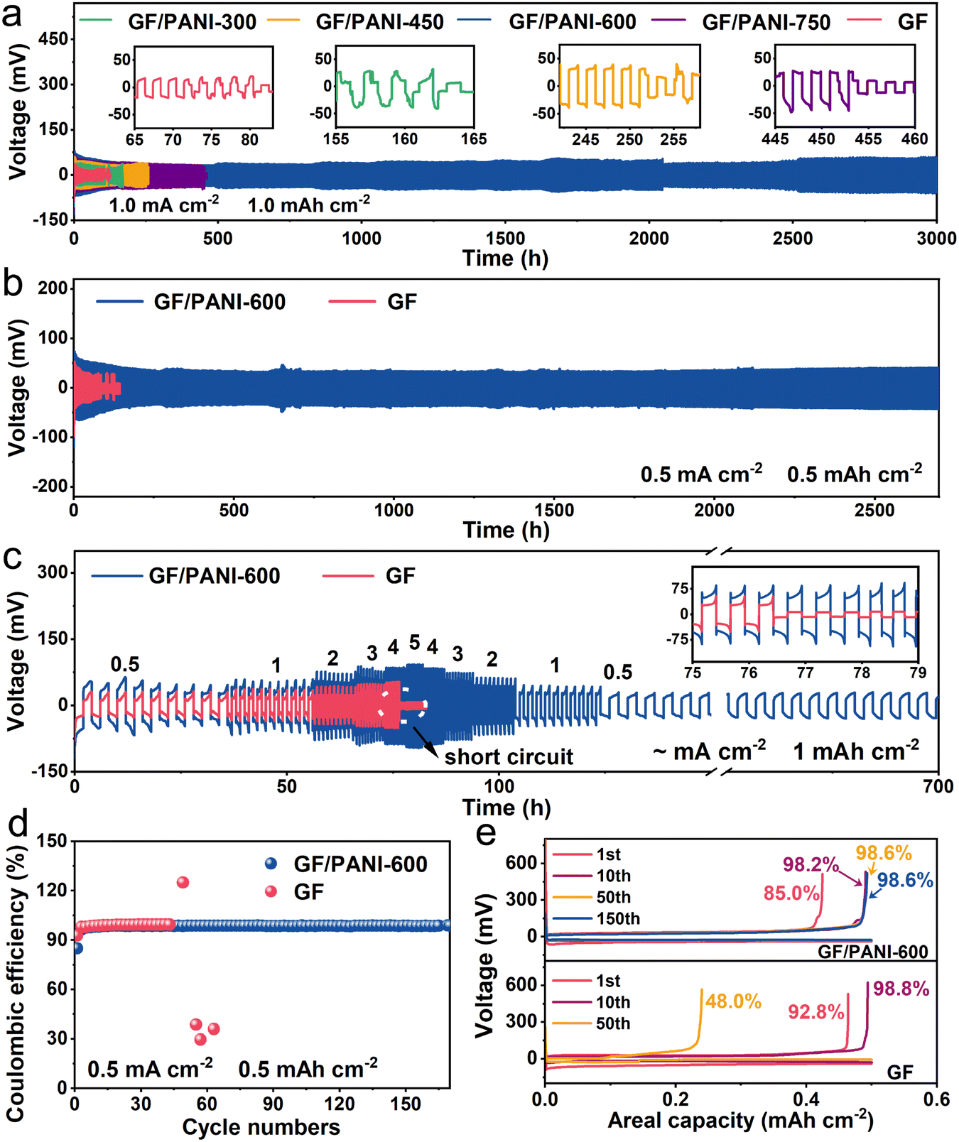 | ||
| Fig. 2 Electrochemical performance of the batteries with GF and GF/PANI-600 separators. Cycling performance at (a) 1.0 mA cm−2, 1.0 mA h cm−2, (b) 0.5 mA cm−2 0.5 mA h cm−2 and (c) rate performance of Zn‖Zn batteries with different separators. (d) Coulombic efficiency of Zn‖Cu asymmetric batteries at 0.5 mA cm−2, 0.5 mA h cm−2 and (e) the corresponding voltage/capacity curves. | ||
Besides that, we also tested Zn‖Cu asymmetric batteries with GF and GF/PANI-600 separators to further assess the positive role of the PANI layer. Fig. S7† shows the CV curves of Zn|GF/PANI-600|Cu and Zn|GF|Cu batteries, which are almost overlapped. The similar positions of redox peaks indicate that the PANI modified separator has good electrochemical stability in the ZnSO4 electrolyte.42 Coulombic efficiency is a key parameter to evaluate the reversibility of the zinc plating and stripping process. Fig. 2d shows the CE of Zn‖Cu asymmetric batteries equipped with GF/PANI-600 and GF separators at 0.5 mA cm−2 with an area capacity of 0.5 mA h cm−2. The Zn|GF/PANI-600|Cu battery delivers a stable CE over 170 cycles, while the Zn|GF|Cu battery displays a sudden fluctuation after 45 cycles. The results imply that the PANI modified GF separator really improves the stability of the plating/stripping process. The corresponding voltage/capacity curves are shown in Fig. 2e; the CE of the Zn|GF/PANI-600|Cu battery in the first cycle is 85.0%, and gradually increases to 98.6% in the 150th cycle. In contrast, the CE of the Zn|GF|Cu battery in the first cycle is 92.8% and declines to 48.0% in the 50th cycle, suggesting an unstable Zn plating/stripping process, which leads to a short circuit. Similarly, the Zn|GF/PANI-600|Cu can retain a long lifespan over 600 cycles at 2.0 mA cm−2 and 1.0 mA h cm−2, far exceeding that of the Zn|GF|Cu battery (only 75 cycles) (Fig. S8†). In a word, the batteries equipped with PANI modified GF separators always display excellent electrochemical performance under various conditions and with ultra-stable Zn metal anodes. The enhanced stability is attributed to the modification of PANI, which can effectively enhance the reversibility of the Zn plating/stripping process.
In order to reveal the effect of PANI modification on a GF separator on the enhanced reversibility of the Zn plating/stripping process, in situ optical microscopic examinations were carried out to trace the plating and stripping process of Zn. The home-made Zn‖Zn symmetric batteries were cycled at 20 mA cm−2 with 4.0 mA h cm−2 using GF/PANI-600 and GF separators. The in situ recorded images are shown in Fig. 3a. It is found that the pristine zinc foil shows a smooth surface at 0 min (Fig. S9†). For the home-made Zn|GF|Zn battery, some scattered deposition spots of Zn gradually emerged on the surface at 6 min, and then these uneven spots continued to enlarge. Some obvious island-like deposition of dendritic Zn on the Zn foil was observed after a 12 min-plating process. These island-like dendrites of Zn still existed after 18 and 24 min stripping processes. In sharp contrast, for the home-made Zn|GF/PANI-600|Zn battery, Zn foil always maintained a relatively smooth and uniform surface during the whole plating and stripping process. Compared with the GF/PANI-600 separator, the obvious aggregation and uneven surface of the Zn anode using a GF separator could be observed from the optical images after a 30 min plating and stripping process (Fig. S10†).
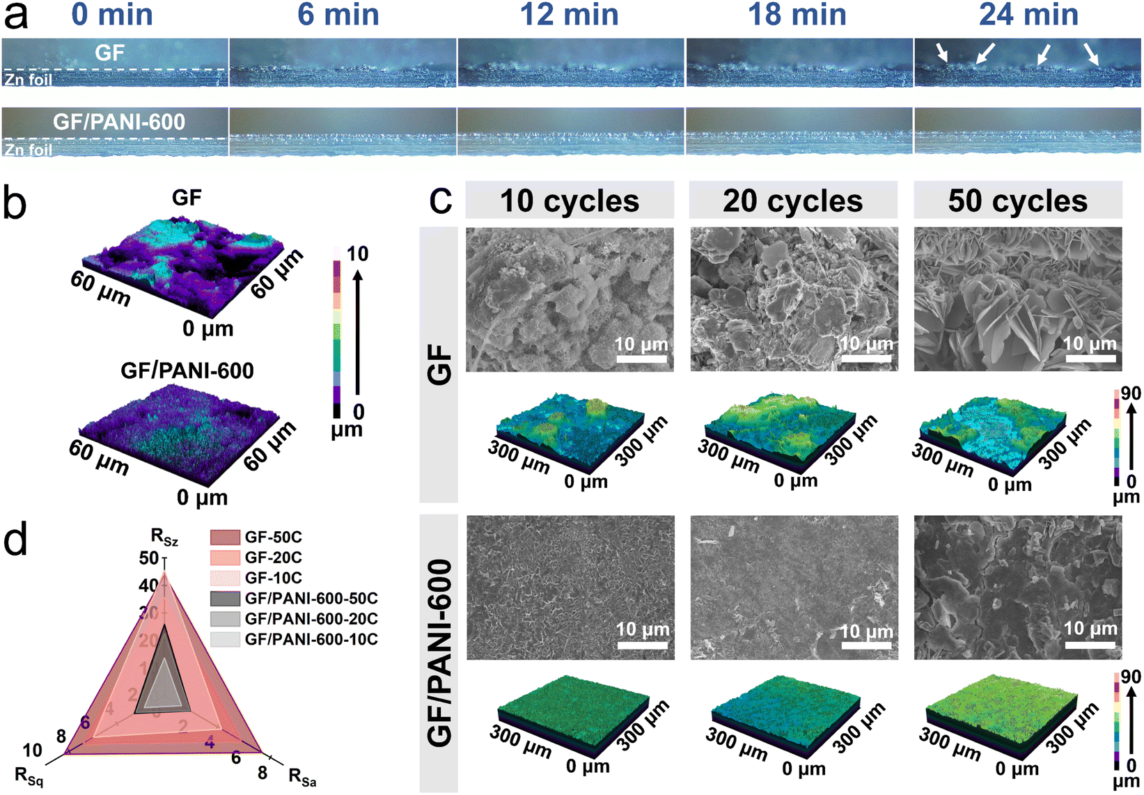 | ||
| Fig. 3 The plating/stripping evolution process of Zn anodes using GF and GF/PANI-600 separators in the Zn‖Zn batteries. (a) In situ optical images at different times and (b) 3D LSM images of the zinc anode surface after 30 min at 20 mA cm−2 with 4.0 mA h cm−2. (c) SEM images and the corresponding 3D LSM images of the zinc anode surface at 0.5 mA cm−2 with 0.5 mA h cm−2 after 10, 20 and 50 cycles. (d) The roughness parameter comparison of the zinc anode surface with different separators after different cycles. | ||
The phenomenon was further demonstrated by the laser confocal microscopy (LSM) three-dimensional (3D) images (Fig. 3b). For the GF separator, the 3D LSM image of the Zn anode displays large aggregates and an uneven deposition surface, while the uniform deposition of Zn is observed for the GF/PANI-600 separator (Fig. 3b). Furthermore, the Zn anodes were collected after different cycles and investigated by SEM examination to uncover the role of the PANI modification layer in prolonging the cycling stability of Zn‖Zn batteries. As shown in Fig. 3c, after 10 cycles of the Zn|GF|Zn battery at 0.5 mA cm−2 with 0.5 mA h cm−2, the island-dendrites emerge on the surface of the Zn anode. As the cycle continues, the island-dendrites continue to grow and evolve into nanosheets (after 50 cycles), which easily leads to the short circuit of the Zn|GF|Zn battery. Different from the Zn|GF|Zn battery, the surface of the Zn anode for the Zn|GF/PANI-600|Zn battery always remains flat and no dendrite-like products appear, indicating uniform Zn deposition on the Zn anode. The XRD patterns of the Zn anode for Zn|GF|Zn and Zn|GF/PANI-600|Zn batteries after 20 cycles are consistent with the standard diffraction peaks of Zn4SO4(OH)6·5H2O (ZSH) (JCPDS no. 39-0688, Fig. S11†), suggesting the formation of ZSH. The corresponding surface topographies of the Zn anode collected at different cycles using different separators are shown in Fig. 3c and S12.† A Zn anode using a GF separator displays a rough surface, while the Zn anode using a GF/PANI-600 separator possesses a flat surface over an area of 9 × 104 μm2. The results imply that the PANI modification layer can guide uniform deposition and stripping of Zn with a flat surface.
Furthermore, the surface roughness parameters consist of arithmetic average surface roughness (RSa), root mean square roughness (RSq) and profile micro-roughness (RSz). As shown in Fig. 3d and Table S2,† all the roughness parameters exhibit an increasing trend with the cycle numbers. Obviously, the roughness parameters of a Zn anode using a GF/PANI-600 separator are significantly smaller than that of a Zn anode using a GF separator. For example, the RSa value for the Zn|GF|Zn battery anode is 7.37 after 50 cycles, while it is declined to 1.96 for a Zn anode using a GF/PANI-600 separator. The cross section of the zinc anode using a GF separator shows an uneven zinc deposition mode with a height of about 15.0 μm after 20 cycles (Fig. S13a†). To make matters worse, there are some sharp dendrites growing towards the GF separator. In contrast, the height of the deposition layer for a GF/PANI-600 separator is only 8.1 μm (Fig. S13b†), and the deposition layer is flat. After 50 cycles at 0.5 mA cm−2 and 0.5 mA h cm−2, the SEM image and elemental mapping results (uniform distribution of C and N elements) on the GF all confirm the existence of a PANI layer (Fig. S14†). The XRD patterns of the GF separator show the diffraction peaks of ZSH with high intensity after 50 cycles at 0.5 mA cm−2 and 0.5 mA h cm−2 (Fig. S15†). In contrast, the diffraction peaks of ZSH for the GF/PANI-600 separator are not obvious, indicating that the modified PANI layer inhibits the growth of dendrites toward the separator. Moreover, the clarified electrolytes were obtained by immersion of the GF/PANI-600 separator in the 2 M ZnSO4 or 2 M ZnSO4 + 0.1 M MnSO4 solution for 60 days, indicating the excellent stability of the PANI modification layer (Fig. S16†). The above results reveal that the PANI layer guides the uniform plating/stripping of zinc and inhibits the growth of Zn dendrites during cycling.
The HER and corrosion reaction of Zn foil are suppressed by the GF/PANI-600 separator, which are confirmed by the linear sweep voltammetry (LSV) curves and Tafel plots (Fig. 4a and b). Under the protection of the PANI layer, the corrosion potential of the zinc anode increases from −0.008 to −0.003 V. Meanwhile, the corrosion current density decreases from 2.835 to 2.210 mA cm−2 using a PANI modified GF separator. The smaller corrosion current helps to slow down the corrosion rate of the zinc anode, and thus enhances the stability of the zinc anode.43 Furthermore, the corrosion resistance of the zinc anode was explored using the Zn‖Zn symmetric batteries using GF and GF/PANI-600 separators, which were cycled for 40 h and then kept at rest for 4 h at 0.5 mA cm−2 with 0.5 mA h cm−2 (Fig. S17†). The Zn|GF/PANI-600|Zn battery maintains stable cycling for 1000 h; however, the Zn|GF|Zn battery presents a short circuit near 200 h. It is attributed to the GF/PANI-600 separator inhibiting the corrosion and side reactions of zinc metal.44 Generally, the migration characteristics of the ions are affected by the ionic conductivity. The ionic conductivity of GF and GF/PANI-600 separators was measured by electrochemical impedance spectroscopy (EIS) in an assembled stainless steel‖stainless steel (SS‖SS) symmetric battery. As shown in Fig. S18,† the ionic conductivity of GF/PANI-600 is 3.25 × 10⁻² mS cm−1, higher than that of the GF (2.46 × 10⁻² mS cm−1), indicating that the modification of PANI promotes the migration of ions.18 The zinc ion transfer numbers (tZn2+) were measured by assembling Zn‖Zn symmetric batteries with GF and GF/PANI-600 separators (Fig. S19†). A high tZn2+ effectively reduces the concentration polarization of Zn2+ and inhibits dendrite growth and side reactions on the interface of the zinc anode and electrolyte.45 The tZn2+ with GF/PANI-600 and GF separators are calculated to be 0.79 and 0.50 (Fig. 4c), respectively. Therefore, the modification of a PANI layer is conducive to alleviate the polarization on the interface and ensure facile transport of Zn2+.
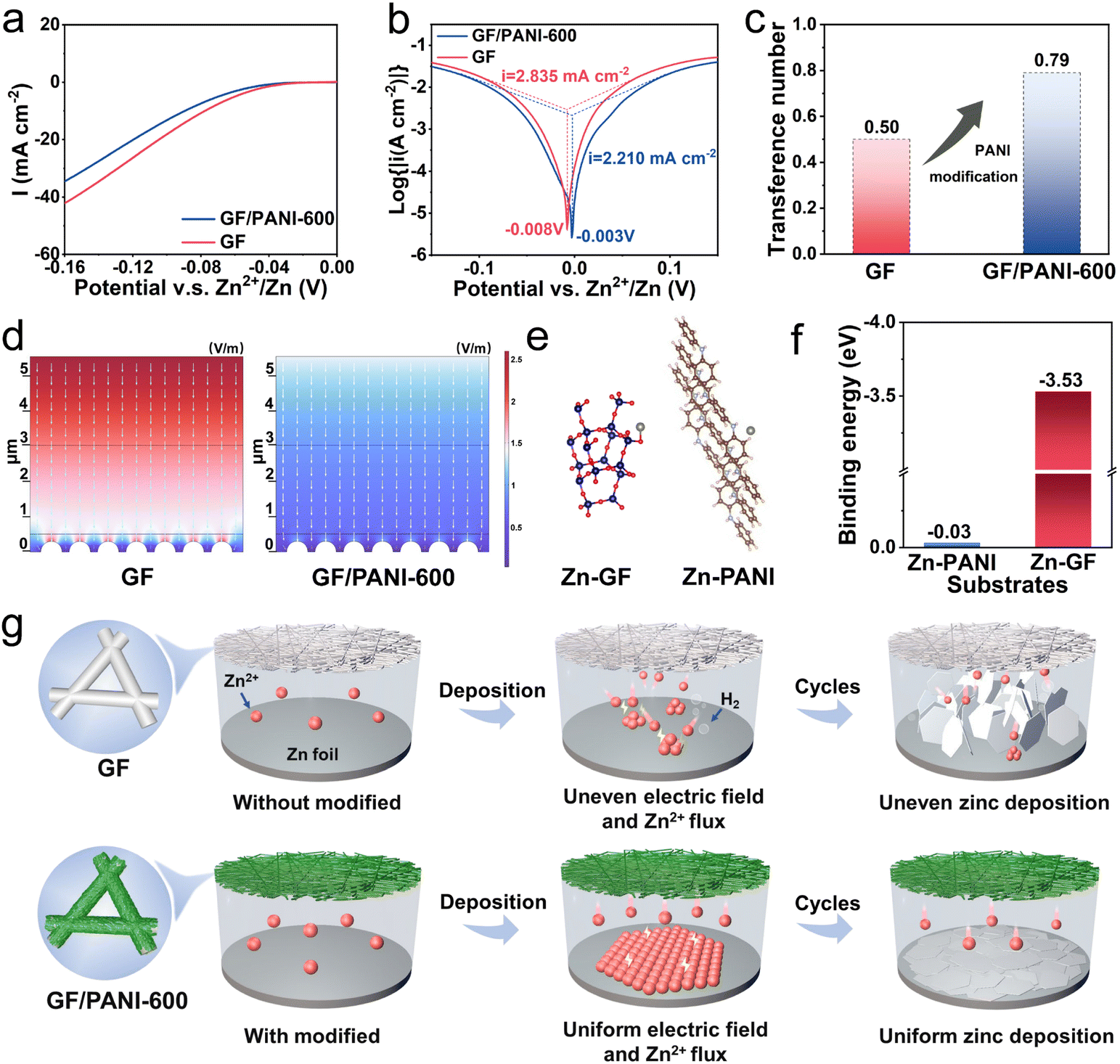 | ||
| Fig. 4 (a) LSV curves at a scan rate of 5.0 mV s−1 and (b) Tafel plots of the Zn‖Zn symmetric batteries with different separators. (c) The calculated transfer number of zinc ions (tZn2+). (d) The electrical field distribution on the GF and GF/PANI-600 separators. (e) Optimized adsorption configurations and (f) the corresponding binding energy of GF and PANI-600 with Zn. (g) The schematic demonstration of the evolution of the plating process on Zn anodes with GF/PANI-600 and pristine GF separators. | ||
Moreover, a microdomain model was built to simulate the electric field distribution of zinc symmetric batteries by COMSOL (Fig. S20†). The corresponding electrical field using GF and GF/PANI-600 separators is shown in Fig. 4d. The inhomogeneous electrical field tends to concentrate on the tip of the dendrite seeds for a pristine GF separator, while the electric field uniformly distributes near the surface of the Zn anode. The inhomogeneous electrical field distribution easily leads to the uneven deposition of Zn2+ and the growth of Zn dendrites on the surface of the Zn metal anode. This conclusion is also verified by the SEM images and in situ optical images (Fig. 3). We also calculated the binding energy of a Zn atom with separators based on the DFT. As shown in Fig. 4e and f, the binding energy was calculated to be −0.03 eV for PANI, which is obviously lower than that of Zn with pristine GF (−3.53 eV). The results indicate that the interaction of Zn with a separator is greatly weakened after modification of the PANI layer.20 For batteries with a GF separator, the uneven distribution of the electric field on the surface of the zinc anode is in favor of the formation of Zn protrusions at an early stage during the plating process. GF attracts Zn growth toward the separator due to higher binding energy with Zn. As a result, the dendrites easily puncture the separator, while the PANI modification layer with abundant functional groups possesses a moderate zincophilic force, which induces the growth of Zn along the edges of the seeds to form a uniform Zn deposition layer (Fig. 4g). In summary, combined with moderate affinity to Zn and a uniform electric field force, the GF/PANI-600 separator guides the uniform deposition of zinc ions and inhibits dendrite growth by the PANI modification layer.
To demonstrate the practicality of a GF/PANI-600 separator in practical applications, the electrochemical performance of Zn|GF/PANI-600|MnO2 full batteries was evaluated using MnO2 nanowires as the cathode, Zn foil as the anode and 2 M ZnSO4 + 0.1 M MnSO4 aqueous solution as the electrolyte. The corresponding XRD pattern and SEM image of the prepared MnO2 nanowires are shown in Fig. S21.† The similar CV curves of Zn‖MnO2 full batteries using GF and GF/PANI-600 separators are displayed in Fig. 5a. The redox peaks of CVs are attributed to the typical redox behavior of MnO2, consistent with the previous reports.46,47 The Zn‖MnO2 battery using a GF/PANI-600 separator shows an improved rate performance, compared with that of the Zn|GF|MnO2 battery (Fig. 5b). When the current densities are 0.2, 0.5, 1.0, 1.5, and 2.0 A g−1, the corresponding discharge average specific capacities of the Zn‖MnO2 battery using a GF/PANI-600 separator are 326.8, 291.5, 255.8, 215.8 and 178.8 mA h g−1, respectively. In addition, when the current density gradually returns to 0.2 A g−1, the specific capacity is also recovered to 336.3 mA h g−1. In contrast, the discharge specific capacity of the Zn|GF|MnO2 battery at 2.0 A g−1 is only 118.6 mA h g−1, and the capacity retention (against the average discharge specific capacity at 0.2 A g−1) of the Zn|GF|MnO2 battery at 2 A g−1 (43.8%) is significantly lower than that of the Zn|GF/PANI-600|MnO2 battery (54.7%, Fig. 5c).
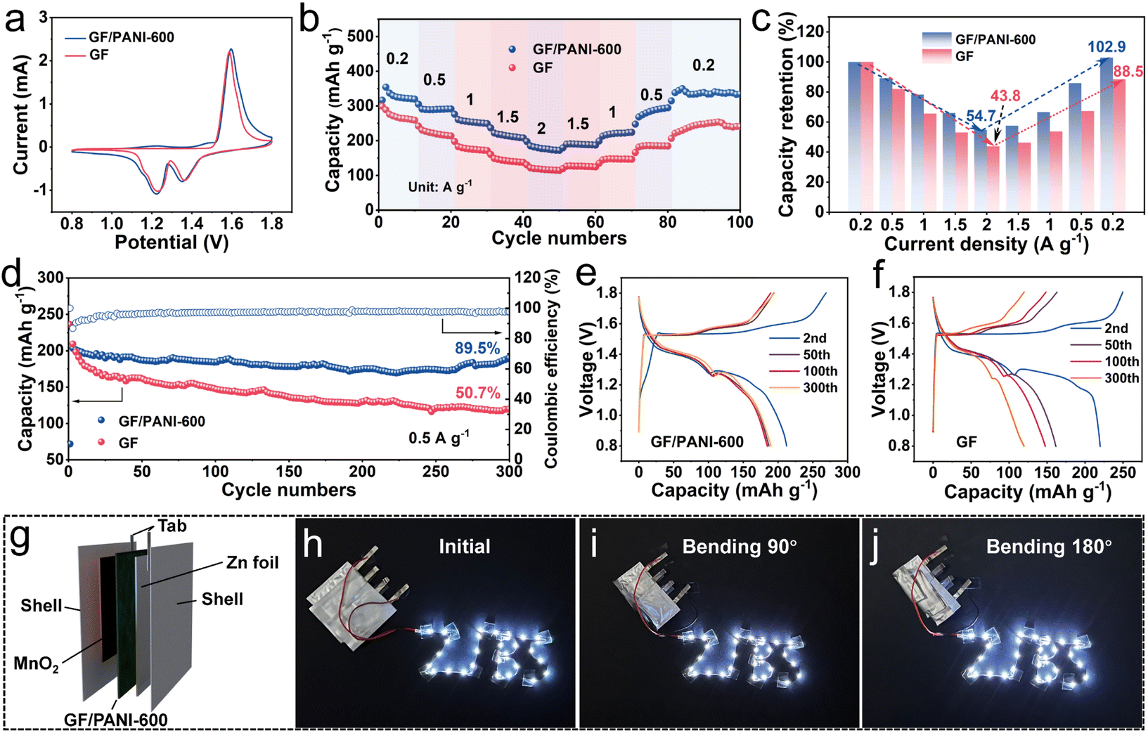 | ||
| Fig. 5 Electrochemical performance of Zn‖MnO2 full batteries using GF and GF/PANI-600 separators. (a) CV curves at 0.1 mV s−1. (b) Rate performance and (c) the corresponding capacity retention of Zn‖MnO2 full batteries. (d) Cycling performance at 0.5 A g−1 and (e and f) the corresponding discharge/charge curves. (g) Schematic illustration of the pouch battery and (h–j) photographs showing the working state of the pouch-type battery in different bending modes. | ||
Besides, the Zn‖MnO2 full battery with a GF/PANI-600 separator delivers a higher specific capacity than the Zn‖MnO2 full battery with a GF separator at a current density of 0.5 A g−1 (Fig. 5d). After 300 cycles, the capacity retention of the Zn|GF/PANI-600|MnO2 battery is 89.5%, while it is only 50.7% for the Zn|GF|MnO2 battery. Even with the full battery cycled at 1.0 A g−1 after 500 cycles, the capacity retention of Zn|GF/PANI-600|MnO2 (60.7%) is still higher than that of Zn|GF|MnO2 (30.4%, Fig. S22†). Meanwhile, the discharge/charge curves of Zn‖MnO2 full batteries using GF and GF/PANI-600 separators are presented in Fig. 5e and f. The charge–discharge curves of the Zn|GF/PANI-600|MnO2 battery are highly overlapped, while the discharge capacity of the Zn|GF|MnO2 battery is gradually declined. The ex situ XRD of MnO2 collected at different states was obtained and is shown in Fig. S23a and b.† Similar diffraction peaks of MnO2 using GF and GF/PANI separators are observed as shown in Fig. S23a and b.† Except the diffraction peaks of MnO2, the obvious diffraction peaks at 2θ = 8.07, 16.22, and 24.43° are indexed to Zn4SO4(OH)6·5H2O (ZSH) (JCPDS no. 39-0688). Besides, the similar CV curves of Zn‖MnO2 full batteries using GF and GF/PANI-600 separators are displayed in Fig. 5a. The above results suggest that the PANI modification layer almost has no influence on the redox behavior of MnO2 for Zn‖MnO2 full batteries. SEM images of the Zn anodes cycled for 20 cycles for Zn‖MnO2 using GF and GF/PANI-600 separators were investigated, as shown in Fig. S23c and d.† For Zn|GF|MnO2 batteries, obvious island-like dendrites are generated on the surface of the Zn anode. In contrast, the Zn anode of Zn|GF/PANI-600|MnO2 maintains a flat surface, because the PANI modification layer induces stable deposition/stripping of Zn, thereby significantly improving the cycling stability of Zn‖MnO2 batteries. As a concept demonstration, pouch batteries were made using GF/PANI-600 separators (Fig. 5g). The light emitting diode (LED) strip lights are successfully powered by the three pouch batteries in series at different bending states (0°, 90°, and 180°, Fig. 5h–j), further demonstrating the potential practical applications of a GF/PANI separator in flexible AZIBs.
Conclusions
In summary, we have successfully developed a PANI modification layer on a commercial GF separator by in situ polymerization of aniline monomers. The PANI modification layer possess a moderate zincophilic force, which can homogenize the surface electric field distribution, inhibit the HER and corrosion reaction of a zinc anode electrode, and guide the uniform plating/stripping of zinc ions. As a result, Zn‖Zn symmetric batteries equipped with GF/PANI-600 display a longer cycle up to 3000 h at 1.0 mA cm−2 with 1.0 mA h cm−2, which is about 43 times larger than that of the comparison sample. In addition, the Zn‖MnO2 full battery with a GF/PANI-600 separator also exhibits a high capacity retention of 89.5% for 300 cycles at 0.5 A g−1 (50.7% of Zn|GF|MnO2 battery). This work provides a new insight into the design of separators to regulate the deposition of Zn ions for long cycle life AZIBs.Author contributions
Fangfang Wu: methodology, formal analysis, data curation, visualization, validation, and writing-review & editing. Fukai Du: preparation and characterization of materials, data curation, validation, and writing-review & editing. Pengchao Ruan and Jiang Zhou: software and data curation. Gangfeng Cai: methodology. Ye Chen: software and data curation. Xinyu Yin and Lu Ma: data curation and review. Ruilian Yin, Wenhui Shi, and Wenxian Liu: visualization, investigation, English editing and polishing. Xiehong Cao: supervision, conceptualization, writing-review & editing and review.Conflicts of interest
There are no conflicts to declare.Acknowledgements
This work was supported by the National Natural Science Foundation of China (22005268, 51972286, and 21905246) and Natural Science Foundation of Zhejiang Provincial Natural Science Foundation (LQ20B010011, LR19E020003, and LZ21E020003). X.C. and F.W. are also thankful for the support from the Leading Innovative and Entrepreneur Team Introduction Program of Zhejiang (2020R01002). This work was supported in part by the High Performance Computing Center of Central South University. X.C. is thankful for the support from theNational Key Research and Development Project of China (2022YFE0113800).
References
- X. Zeng, J. Mao, J. Hao, J. Liu, S. Liu, Z. Wang, Y. Wang, S. Zhang, T. Zheng, J. Liu, P. Rao and Z. Guo, Adv. Mater., 2021, 33, 2007416 CrossRef CAS PubMed.
- A. Bayaguud, X. Luo, Y. Fu and C. Zhu, ACS Energy Lett., 2020, 5, 3012–3020 CrossRef CAS.
- J. Zheng, Y. Wu, H. Xie, Y. Zeng, W. Liu, A. N. Gandi, Z. Qi, Z. Wang and H. Liang, ACS Nano, 2023, 17, 337–345 CrossRef CAS PubMed.
- F. Wu, Y. Wang, P. Ruan, X. Niu, D. Zheng, X. Xu, X. Gao, Y. Cai, W. Liu, W. Shi and X. Cao, Mater. Today Energy, 2021, 21, 100842 CrossRef CAS.
- G. Li, X. Wang, S. Lv, J. Wang, W. Yu, X. Dong and D. Liu, Adv. Funct. Mater., 2023, 33, 2208288 CrossRef CAS.
- J. Wang, Z. Zhao, F. Hu, H. Song, Q. Xie, X. Wan and S. Song, Chem. Eng. J., 2023, 451, 139058 CrossRef CAS.
- Y. Zhang, C. Peng, Y. Zhang, S. Yang, Z. Zeng, X. Zhang, L. Qie, L.-L. Zhang and Z. Wang, Chem. Eng. J., 2022, 448, 137653 CrossRef CAS.
- Y. Shang, P. Kumar, T. Musso, U. Mittal, Q. Du, X. Liang and D. Kundu, Adv. Funct. Mater., 2022, 32, 2200606 CrossRef CAS.
- X. Xu, Y. Chen, D. Zheng, P. Ruan, Y. Cai, X. Dai, X. Niu, C. Pei, W. Shi, W. Liu, F. Wu, Z. Pan, H. Li and X. Cao, Small, 2021, 17, 2101901 CrossRef CAS PubMed.
- H. Yang, Z. Chang, Y. Qiao, H. Deng, X. Mu, P. He and H. Zhou, Angew. Chem., Int. Ed., 2020, 59, 9377–9381 CrossRef CAS PubMed.
- Y. Cui, Q. Zhao, X. Wu, X. Chen, J. Yang, Y. Wang, R. Qin, S. Ding, Y. Song, J. Wu, K. Yang, Z. Wang, Z. Mei, Z. Song, H. Wu, Z. Jiang, G. Qian, L. Yang and F. Pan, Angew. Chem., Int. Ed., 2020, 59, 16594–16601 CrossRef CAS PubMed.
- Z. Cai, Y. Ou, J. Wang, R. Xiao, L. Fu, Z. Yuan, R. Zhan and Y. Sun, Energy Storage Mater., 2020, 27, 205–211 CrossRef.
- Y. Zeng, X. Zhang, R. Qin, X. Liu, P. Fang, D. Zheng, Y. Tong and X. Lu, Adv. Mater., 2019, 31, 1903675 CrossRef PubMed.
- F. Wu, Y. Chen, Y. Chen, R. Yin, Y. Feng, D. Zheng, X. Xu, W. Shi, W. Liu and X. Cao, Small, 2022, 18, 2202363 CrossRef CAS PubMed.
- J. Hao, L. Yuan, C. Ye, D. Chao, K. Davey, Z. Guo and S. Z. Qiao, Angew. Chem., Int. Ed., 2021, 60, 7366–7375 CrossRef CAS PubMed.
- Y. An, Y. Tian, K. Zhang, Y. Liu, C. Liu, S. Xiong, J. Feng and Y. Qian, Adv. Funct. Mater., 2021, 31, 2101886 CrossRef CAS.
- Y. Liang, D. Ma, N. Zhao, Y. Wang, M. Yang, J. Ruan, G. Yang, H. Mi, C. He and P. Zhang, Adv. Funct. Mater., 2022, 32, 2112936 CrossRef CAS.
- C. Li, Z. Sun, T. Yang, L. Yu, N. Wei, Z. Tian, J. Cai, J. Lv, Y. Shao, M. H. Rummeli, J. Sun and Z. Liu, Adv. Mater., 2020, 32, 2003425 CrossRef CAS PubMed.
- Y. Qin, P. Liu, Q. Zhang, Q. Wang, D. Sun, Y. Tang, Y. Ren and H. Wang, Small, 2020, 16, 2003106 CrossRef CAS PubMed.
- H. Gan, J. Wu, F. Zhang, R. Li and H. Liu, Energy Storage Mater., 2023, 55, 264–271 CrossRef.
- J. Zhu, Z. Bie, X. Cai, Z. Jiao, Z. Wang, J. Tao, W. Song and H. J. Fan, Adv. Mater., 2022, 34, 2207209 CrossRef CAS PubMed.
- Z. Yang, W. Li, Q. Zhang, C. Xie, H. Ji, Y. Tang, Y. Li and H. Wang, Mater. Today Energy, 2022, 28, 101076 CrossRef CAS.
- W. Zhou, M. Chen, Q. Tian, J. Chen, X. Xu and C.-P. Wong, Energy Storage Mater., 2022, 44, 57–65 CrossRef.
- B. Wu, Y. Wu, Z. Lu, J. Zhang, N. Han, Y. Wang, X.-m. Li, M. Lin and L. Zeng, J. Mater. Chem. A, 2021, 9, 4734–4743 RSC.
- Y. Fang, X. Xie, B. Zhang, Y. Chai, B. Lu, M. Liu, J. Zhou and S. Liang, Adv. Funct. Mater., 2022, 32, 2109671 CrossRef CAS.
- Y. Su, B. Liu, Q. Zhang, J. Peng, C. Wei, S. Li, W. Li, Z. Xue, X. Yang and J. Sun, Adv. Funct. Mater., 2022, 32, 2204306 CrossRef CAS.
- J. Huang, Z. Wang, M. Hou, X. Dong, Y. Liu, Y. Wang and Y. Xia, Nat. Commun., 2018, 9, 2906 CrossRef PubMed.
- D. Feng, Y. Jiao and P. Wu, Angew. Chem., Int. Ed., 2023, 62, e202215060 CAS.
- Y. Zhang, M. Zhu, G. Wang, F. H. Du, F. Yu, K. Wu, M. Wu, S. X. Dou, H. K. Liu and C. Wu, Small Methods, 2021, 5, 2100650 CrossRef CAS PubMed.
- G. Kresse and J. Hafner, Phys. Rev. B: Condens. Matter Mater. Phys., 1993, 48, 13115–13118 CrossRef CAS PubMed.
- P. E. Blochl, Phys. Rev. B: Condens. Matter Mater. Phys., 1994, 50, 17953–17979 CrossRef PubMed.
- J. P. Perdew, K. Burke and M. Ernzerhof, Phys. Rev. Lett., 1997, 78, 1396 CrossRef CAS.
- P. H. Cao, H. C. Zhou, X. Y. Zhou, Q. Du, J. J. Tang and J. Yang, ACS Sustainable Chem. Eng., 2022, 10, 8350–8359 CrossRef CAS.
- W. Shao, R. Jamal, F. Xu, A. Ubul and T. Abdiryim, Materials, 2012, 5, 1811–1825 CrossRef CAS.
- S. M. Reda and S. M. Al-Ghannam, Adv. Mater. Phys. Chem., 2012, 02, 75–81 CrossRef CAS.
- V. J. Babu, S. Vempati and S. Ramakrishna, Mater. Sci. Appl., 2013, 04, 1–10 CAS.
- M. Trchová, Z. Morávková, M. Bláha and J. Stejskal, Electrochim. Acta, 2014, 122, 28–38 CrossRef.
- J. An, J. Liu, Y. Zhou, H. Zhao, Y. Ma, M. Li, M. Yu and S. Li, J. Phys. Chem. C, 2012, 116, 19699–19708 CrossRef CAS.
- A. Stott, M. O. Tas, E. Y. Matsubara, M. G. Masteghin, J. M. Rosolen, R. A. Sporea and S. R. P. Silva, Energy Environ. Mater., 2020, 3, 389–397 CrossRef CAS.
- J. X. Deng, T. M. Wang, J. S. Guo and P. Liu, Prog. Nat. Sci.: Mater. Int., 2017, 27, 257–260 CrossRef CAS.
- V. H. Nguyen and J.-J. Shim, J. Spectrosc., 2015, 2015, 297804 Search PubMed.
- C. Peng, Y. Zhang, S. Yang, L.-L. Zhang and Z. Wang, Nano Energy, 2022, 98, 107329 CrossRef CAS.
- L. Zhou, F. Wang, F. Yang, X. Liu, Y. Yu, D. Zheng and X. Lu, Angew. Chem., Int. Ed., 2022, 61, e202208051 CAS.
- H. Yu, Y. Chen, W. Wei, X. Ji and L. Chen, ACS Nano, 2022, 16, 9736–9747 CrossRef CAS PubMed.
- Y. C. Liang, Y. Y. Wang, H. W. Mi, L. N. Sun, D. T. Ma, H. W. Li, C. X. He and P. X. Zhang, Chem. Eng. J., 2021, 425, 131862 CrossRef CAS.
- J. Cao, D. Zhang, C. Gu, X. Zhang, M. Okhawilai, S. Wang, J. Han, J. Qin and Y. Huang, Nano Energy, 2021, 89, 106322 CrossRef CAS.
- S. Tao, C. Zhang, J. Zhang, Y. Jiao, M. Li, W. Lin, L. Ran, B. Clement, M. Lyu, I. Gentle, L. Wang and R. Knibbe, Chem. Eng. J., 2022, 446, 136607 CrossRef CAS.
Footnote |
| † Electronic supplementary information (ESI) available. See DOI: https://doi.org/10.1039/d3ta01344h |
| This journal is © The Royal Society of Chemistry 2023 |