
 Open Access Article
 This Open Access Article is licensed under a
 Creative Commons Attribution 3.0 Unported Licence
Fuel cell electrode degradation followed by identical location transmission electron microscopy†
Victor
Shokhen‡
 *ab,
Linnéa
Strandberg‡
ab,
Magnus
Skoglundh
bc and
Björn
Wickman
*ab
*ab,
Linnéa
Strandberg‡
ab,
Magnus
Skoglundh
bc and
Björn
Wickman
*ab
aDepartment of Physics, Chalmers University of Technology, SE-412 96 Göteborg, Sweden. E-mail: victor.shokhen@chalmers.se; bjorn.wickman@chalmers.se
bCompetence Centre for Catalysis, Chalmers University of Technology, SE-412 96 Göteborg, Sweden
cDepartment of Chemistry and Chemical Engineering, Chalmers University of Technology, SE-412 96 Göteborg, Sweden
First published on 4th September 2023
Abstract
Identical location transmission electron microscopy (IL-TEM) is a powerful technique that has previously been used to study degradation of catalyst materials for proton exchange membrane fuel cells (PEMFCs) in half-cell environments. Here, we demonstrate that IL-TEM can be used to follow degradation at the top of the catalytic Pt/C layer in a real PEMFC on the atomic scale under operation. We find that during an accelerated stress test (AST), mimicking normal operation, Pt nanoparticles grow mainly by Ostwald ripening, while the carbon support is stable. Under AST mimicking start-up/shutdown conditions, the carbon support degrades mainly by loss of volume and collapse, which forces the Pt nanoparticles closer, promoting additional particle growth. The observed degradation correlates with the measured decrease in electrochemical performance for the respective AST. The results show the feasibility of performing IL-TEM imaging in PEMFCs under real-operating conditions, opening up the possibility for similar studies in other fully operational systems.
Proton exchange membrane fuel cells (PEMFCs) are, due to their high efficiency in converting chemical energy stored in hydrogen to electricity without CO2 emissions, a potential replacement for e.g., fossil-fuelled engines, to reduce carbon emissions from the transport sector and stationary power sources.1–3 While PEMFCs are used in several commercial applications, they still need improvement both in terms of activity and stability.2,4 Currently, Pt nanoparticles on high surface area carbon supports (Pt/C), coated with an ionomer (typically Nafion) for ion conduction, are the standard catalyst used in PEMFCs. While Pt has high activity and is more stable than its alternatives,5 it is expensive and suffers from degradation-related issues.6,7 To design catalysts with superior activity and stability for PEMFCs, the mechanisms for degradation need to be better understood, and thus degradation studies of the catalyst under relevant conditions are essential.8–11
Many techniques have been used to study catalyst degradation in PEMFCs, often by combining electrochemical performance measurements with in situ and ex situ characterisation.7–9,12,13 For example, the catalyst surface can be characterised by microscopic imaging at the beginning of life (BOL) and end of life (EOL) of the catalyst.6,14 Identical location (IL) techniques, such as IL transmission electron microscopy (TEM), have been used to study ageing of electrocatalysts for fuel cell purposes.15–17 However, these studies have mainly been performed in half-cell setups, in liquid environments at room temperature, and not under real-operating conditions of the fuel cell, i.e., in the presence of humidified gases, at higher temperatures, and where the catalyst interacts with the gas diffusion layer (GDL) and the solid ionomer, due to challenges with performing studies in full PEMFC systems.17,18 It is unclear how ageing from liquid half-cell studies translates to degradation in real PEMFC environments.19,20 Lazaridis et al. suggested that due to the fundamental differences between rotating disc electrodes (RDEs) and PEMFCs, measurements from RDE set-ups have limited transferability to real PEMFCs.21
It has been suggested that under start-up/shutdown conditions, the Pt/C catalyst degrades only by carbon corrosion, without any Pt particle growth,22 while others have reported that similar conditions lead to carbon corrosion promoting Pt particle agglomeration23 or Pt detachment without visible carbon corrosion.24 The different results reported in the literature might be due either to these studies being performed without microscopy imaging to support the proposed degradation mechanisms or not being performed under realistic conditions in real fuel cell systems.
In this study, we target these problems by implementing IL-TEM imaging in a real PEMFC system, to study Pt/C degradation to shed light on different types of degradation mechanisms in the cathodic catalyst layer (CCL) by conducting two types of accelerated stress tests (ASTs). Intermediate electrochemical characterisation followed by TEM imaging makes it possible to follow the degradation processes on a nanoscopic scale after each AST session. A milder AST is used to mimic normal fuel cell operation while a harsher AST is used to mimic start-up/shutdown events. Full details about the experimental procedure can be found in the ESI.†
The methodology for sample preparation and insertion of the TEM grid into the PEMFC is illustrated in Fig. 1. Different TEM grids are used depending on the type of AST. A golden grid with conductive lacey carbon is used for the normal operation AST, on which a large amount of sample can be attached and easily tracked. A golden hollow carbon-film-free TEM grid is used for the start-up/shutdown AST, to avoid degradation effects of the supporting carbon film.25
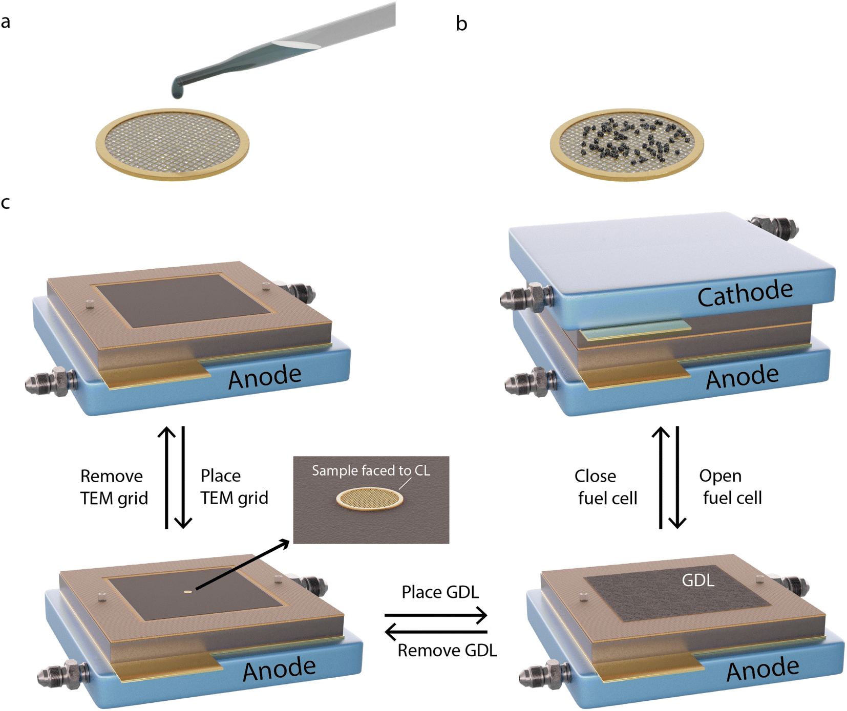 | ||
| Fig. 1 Schematic illustration of the methodology. A suspension of Pt/C in Milli-Q water is dropcast onto the carbon film covered side of a TEM grid (a and b) and is let to air dry. (c) The grid is inserted in-between the CCL and GDL of a MEA with the uncovered side of the grid facing upwards, and the full MEA is inserted into a 5 cm2 single-cell PEMFC. After electrochemical characterisation, the fuel cell is opened and the GDL is removed from the CCL to expose the TEM grid, which is then removed for IL-TEM imaging. The process in step c is then repeated for further AST procedures. | ||
To deposit the catalyst on the grids, a small amount of Pt/C is scraped off from the CCL side of a commercial Pt/C membrane electrode assembly (MEA). The sample is then mixed with Milli-Q water (18 MΩ cm at 25 °C) to form a suspension, which is deposited onto one side of the TEM grid (Fig. 1a and b). The grids are placed between the CCL and the GDL in the MEA (Fig. 1c), with the coated side of the grid facing the CCL to provide electron and proton contact and with the uncoated side in contact with the GDL to provide electrical contact. The MEA is inserted into the fuel cell for electrochemical measurements. After potential cycling followed by electrochemical characterisation, the cell is opened and the cathode side GDL and the TEM grid are gently removed. After IL-TEM imaging, the same grid and GDL are placed back in the MEA, with the same orientation, which is reinserted in the fuel cell for further potential cycling. It has been shown that careful dismantling and reassembling of the PEMFC does not harm the fuel cell performance.26 The amount of catalyst material on the TEM grids was sufficiently small (Fig. S1†) to not generate any noticeable difference in the overall polarisation curves.
The polarisation curves after 5000, 10![[thin space (1/6-em)]](https://www.rsc.org/images/entities/char_2009.gif) 000 and 15000 potential cycles during the normal operation AST (Fig. 2a) show that the fuel cell performance only decreases slightly, from 251 mA cm−2 at the BOL to 183 mA cm−2 at the EOL, at 0.7 V. Analogous performance losses have been reported for a comparable MEA with a similar AST by Perego et al.22 The cyclic voltammograms (CVs) (Fig. 2b) show that the current decreases throughout the potential cycling. The most drastic decrease is seen between the BOL and 5000 cycles. In particular, the region associated with hydrogen underpotential deposition (Hupd) decreases during the potential cycling, which correlates with a decrease in the electrochemically active surface area (ECSA) (Fig. 2c).27 At the EOL, the ECSA has decreased by about 85% from 62 to 9 m2 gpt−1. The rather low decrease in activity in our study is also evident from the Tafel slopes that throughout the AST are around 70 mV dec−1 (Table S1†). Zirhul et al. reported a similar value where a 90% loss of the ECSA results in a voltage decrease of 70 mV,28 and Harzer et al. reported an ECSA loss of 82% from about 55 m2 gpt−1 to 10 m2 gpt−1 after 10000 potential cycles with a similar type of AST.10
000 and 15000 potential cycles during the normal operation AST (Fig. 2a) show that the fuel cell performance only decreases slightly, from 251 mA cm−2 at the BOL to 183 mA cm−2 at the EOL, at 0.7 V. Analogous performance losses have been reported for a comparable MEA with a similar AST by Perego et al.22 The cyclic voltammograms (CVs) (Fig. 2b) show that the current decreases throughout the potential cycling. The most drastic decrease is seen between the BOL and 5000 cycles. In particular, the region associated with hydrogen underpotential deposition (Hupd) decreases during the potential cycling, which correlates with a decrease in the electrochemically active surface area (ECSA) (Fig. 2c).27 At the EOL, the ECSA has decreased by about 85% from 62 to 9 m2 gpt−1. The rather low decrease in activity in our study is also evident from the Tafel slopes that throughout the AST are around 70 mV dec−1 (Table S1†). Zirhul et al. reported a similar value where a 90% loss of the ECSA results in a voltage decrease of 70 mV,28 and Harzer et al. reported an ECSA loss of 82% from about 55 m2 gpt−1 to 10 m2 gpt−1 after 10000 potential cycles with a similar type of AST.10
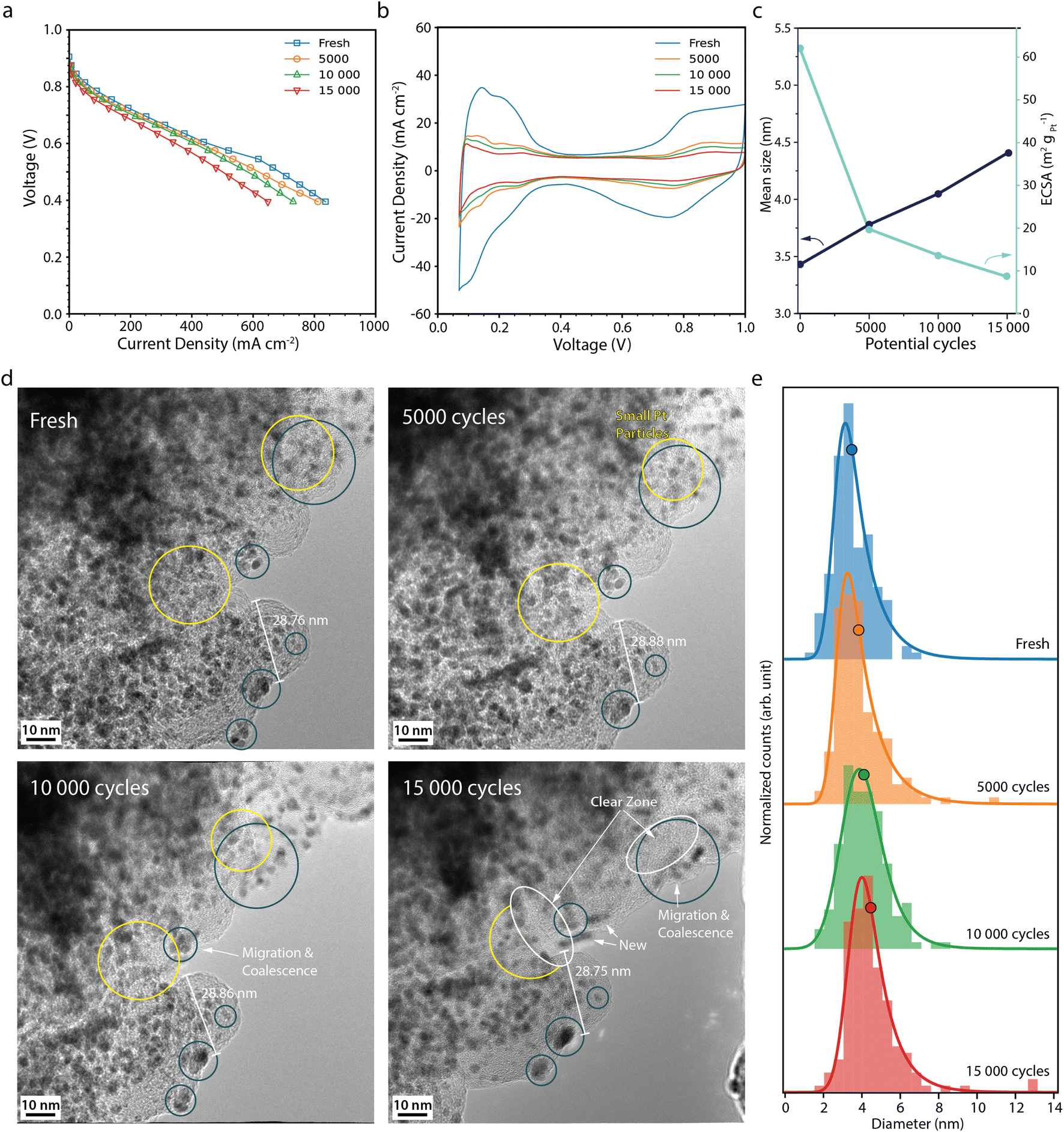 | ||
| Fig. 2 (a) Polarisation curves measured potentiostatically, and (b) cyclic voltammograms recorded at 100 mV s−1 for the fresh fuel cell and after 5000, 10000 and 15000 normal operation AST potential cycles. (c) Mean Pt particle size (black) and available Pt surface area, ECSA, (light blue) versus the number of potential cycles. (d) Corresponding IL-TEM images, and (e) corresponding Pt particle size distributions. The histograms, from 150 Pt particles at each point in time, are fitted with an exponentially modified Gaussian function, and the mean diameter is marked with a circle. | ||
Fig. 2d shows IL-TEM images from the normal operation AST. At the BOL, the TEM images show Pt particles in the range of 2–4 nm in diameter being evenly distributed throughout the carbon support. Over the course of the AST, some particles migrate towards each other and coalesce (blue circles), gradually merging to form larger particles. Smaller particles are seen to shrink in tandem with larger neighbour particles growing (yellow circles), most likely due to Ostwald ripening initiated by platinum dissolution/redeposition.6,29–31 Close-up images of Pt particles merging and growing by Ostwald ripening can be found in Fig. S2.† Furthermore, some of the particles disappear and some new particles appear, indicating that particles detach/dissolve and redeposit at other locations. Overall, more larger Pt particles are seen on the carbon support at the EOL with regions free from particles (white circles) and fewer small particles, which is reflected in the upward shift of the Pt particle size distributions (Fig. 2e) and the mean Pt particle size (Fig. 2c), which increases from 3.4 nm at BOL to 4.4 nm after 15000 potential cycles. Similar Pt degradation behaviour was observed by IL-SEM in our previous study.26 Degradation of the carbon support appears negligible under these conditions.
Moreover, the extensive loss in ECSA cannot be fully explained by Pt particle growth. Assuming no Pt mass is lost, the increase in average Pt particle size should only give about a 20% loss in surface area, showing that other processes in the electrode must also take place to explain the loss in ECSA. The total volume of Pt was calculated for a well-defined area at the BOL and EOL. While the average Pt particle volume increases by more than a factor of two, the total volume of all Pt particles decreases by 5%, due to a ca 45% decrease in the number of particles, showing that some Pt mass is lost from the area during the AST. Still, the measured loss in total Pt volume and increase in average particle size cannot fully explain the loss in ECSA. Due to the placement of the TEM grids during the AST, the TEM analysis shows the degradation taking place at the top of the CL. Degradation throughout the depth of the CL is known to vary and to be more severe closer to the membrane. Inhomogeneous Pt particle growth throughout the depth of the CCL and deposition of Pt inside the membrane,32 where it is not in electrical contact, could further add up the loss in ECSA.
The fuel cell performance decreases much more rapidly during the start-up/shutdown AST (Fig. 3a) than during the normal operation AST, from 244 mA cm−2 at the BOL to 28 mA cm−2 at the EOL, at 0.7 V. This behaviour is in line with previously published data, where it has been suggested that degradation of the carbon support leads to Pt detachment and loss of the ionomer and loss of porosity, which in turn leads to performance losses due to mass transport limitations.22,33 The CVs from the start-up/shutdown AST (Fig. 3b) show a current decrease in the Hupd region, correlating to a loss in ECSA by 68%, from 62 to 20 m2 gpt−1 between the BOL and EOL (Fig. 3c). Perego et al. performed a similar carbon corroding AST method, where the ECSA was reported to have decreased by ca. 58% after 1000 start-up/shutdown potential cycles, from 40 m2 gpt−1 up to 17 m2 gpt−1,22 which is in agreement with our ECSA loss, of ca. 55–60% after 1000 cycles (interpolated from Fig. 3c).
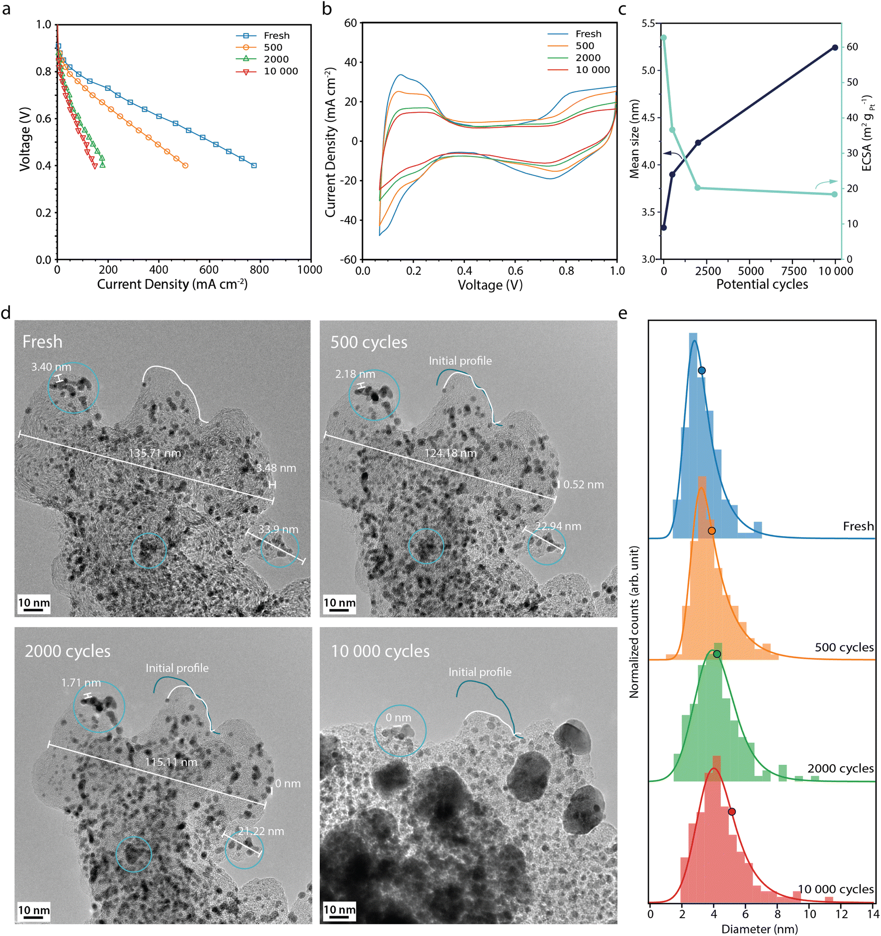 | ||
| Fig. 3 (a) Polarisation curves measured potentiostatically, and (b) cyclic voltammograms recorded at 100 mV s−1 recorded for the fresh fuel cell and after 500, 2000 and 10000 start-up shutdown AST potential cycles. (c) Mean Pt particle size (black) and the electrochemically active surface area, ECSA (light blue) versus the number of potential cycles. (d) Corresponding IL-TEM images and (e) corresponding Pt particle size distributions. The histograms, from 150 Pt particles at each point in time, are fitted with an exponentially modified Gaussian function, and the mean diameter is marked with a circle. The x-axis of histograms shown here is limited to <14 nm, but it is important to note that larger particles (>20 nm) are observed after extensive ageing. The full set of Pt particles is used to calculate the mean size and the full histograms can be found in Fig. S4.† | ||
The IL-TEM images for the start-up/shutdown AST (Fig. 3d) are taken from a location of the sample that has survived until the EOL. Much of the sample does not survive the full AST, due to detachment from weak anchor points; thus the IL-TEM images presented here suffer somewhat from survivor bias. Likely, the areas not present at the EOL have faced more severe degradation and hence have not survived the full AST. The IL-TEM images from the start-up/shutdown AST show clear differences as compared to those from the normal operation AST. The images from the BOL are similar. However, already after a few hundred potential cycles, signs of carbon corrosion can be seen. The distances between features on the support, such as Pt particles, decrease due to carbon shrinking,34 indicating loss of the material. After 2000 cycles, the surface area of the carbon structure seen in Fig. 3d shrinks by around 21% and area losses of up to 50% are seen at the EOL at other locations (see Fig. S3†). Between 2000 and 10000 cycles, parts of the carbon structure collapse, making it difficult to define the same area for the IL-TEM analysis. At the EOL, large particles in the size range of 20-30 nm, indicated to be Pt by the d-spacing of the fringe pattern (Fig. S5†), can be seen all over the support. The appearance of some of these large particles cannot be explained by the surrounding particles agglomerating; rather these particles have more likely detached from other locations due to the loss and collapse of the support and redeposited on what support is left.
The histograms (Fig. 3e) show that the Pt particles grow faster and larger during the start-up/shutdown AST than during the normal operation AST, from 3.3 nm at the BOL to 5.2 nm after 10000 potential cycles. The loss in volume of the carbon support and loss of Pt/ionomer contact,22 even in the early stage of the AST, force the Pt particles closer to each other, which promotes stronger agglomeration and coalescence compared to the normal operation AST (Fig. 2e). Interestingly, the ECSA decreases more during the normal operation AST than during the more aggressive start-up/shutdown AST, contrary to the growth pattern of the Pt particles observed with TEM, where the particles grow more during the start-up/shutdown AST (Fig. 2c and 3c). Also here the increase in average Pt particle diameter is still not large enough to fully explain the decrease in ECSA and would only give about 38% loss in surface area, once again showing that other effects also must contribute.
The observed severe degradation of the carbon support could in part explain the extensive loss of performance seen during the start-up/shutdown AST, provided that the degradation of the carbon support proceeds throughout the surface of the CCL and not only locally on the TEM grid. If the support collapses, physical contact in the CCL could be lost, reducing the overall electron and proton conductivity and increasing contact resistivity. Furthermore, loosely attached Pt particles might detach, due to loss of the support, and reattach at locations without sufficient contact with either the ionomer or carbon support. It should be noted that the grids are placed at the top of the CCL. As we have shown previously,26 the degradation is not homogeneous throughout the cross-section of the CCL, with particles tending to accumulate closer to the membrane. Thus, while the degradation presented here may show the degradation near the top of the CCL, it does not necessarily translate completely to the degradation closer to the membrane. It would be interesting to place grids at different positions (heights) in the electrode, but due to difficulties with inserting and removing the grid in a reproducible way without permanently damaging the grid or the electrode this was not attempted here.
When comparing the results presented here to those of previous IL-TEM studies carried out in liquid three-electrode cells, the Pt particles degrade less severely under real fuel cell operation conditions compared to liquid conditions.18,23,24,35,36 In particular, Pt particle detachment seems to be more prevalent in liquid environments compared to real fuel cell conditions, which could at least in part be due to the gaseous environment being less likely to transport the particles away from their positions. IL-TEM studies performed in gaseous half-cell setups show results more similar to the results presented here, with slower Pt particle growth and less particle detachment.19,37,38 H. Yu et al.36 tried to solve the issues with discrepancies between wet-cell measurements and real MEA measurements, by changing the AST parameters, such as the voltage window. While they achieved degradation more similar to that observed inside an MEA, they did so by changing the type of AST tested. Thus, it is not clear how to modify another type of AST to gain the same results in wet-cell and MEA measurements, or indeed if it is even possible, nor is it clear if the modes of degradation during those modified ASTs are still relevant for the degradation in real MEAs under those conditions that one originally intended to study. Furthermore, they speculate that other adaptations of the experimental conditions might be needed for testing other catalysts, meaning the transferability of their method to other catalysts is uncertain. Rather than trying to modify ASTs for use under wet cell conditions, we use the intended type of AST and perform the measurements in a system much closer to the intended application. Implementing IL-TEM in a single-cell PEMFC is a major step in the development of better methods for characterising catalyst degradation in PEMFCs. It combines the key strengths of IL-TEM, such as identification of specific local degradation phenomena on the nanoscopic scale, and combines them with the strengths of performing measurements in PEMFCs, such as data more relevant for the catalyst degradation in real fuel cells.
Another set of measurements performed using TEM grids with a non-conductive layer (Formvar) show no noticeable degradation from the electrochemical procedures or changes to the catalyst even after extensive normal operation potential cycling (see Fig. S6†), showing that the Pt/C catalyst on the TEM grid must be in electrical contact with the catalyst layer and GDL to undergo any degradation. This, together with the observation that different types of degradation observed by IL-TEM imaging occur depending on which type of AST the fuel cell is subjected to, leads us to conclude that the Pt particles on the TEM grids indeed are in electrochemical contact with the CCL and GDL, that the degradation of the particles on the TEM grid is due to the type of AST applied, and that the degradation of the Pt particles on the grids is indicative of the degradation taking place in the CCL. It is possible that the TEM grids change the local environment, thus affecting the observed degradation. However, the TEM grids either have no carbon film at all or the holes in the carbon-covered grids are much larger than the average pore size of the carbon support structure, and the observed samples were located in the openings of the holes to not have the view obstructed by the carbon film. Thus, mass transport limitations due to blocking by the grid should not be prevalent. If such issues exist, similar effects should also be present in half-cell measurements and the results presented here should still give an indication of how results obtained in half-cells and PEMFCs compare to each other. Other techniques such as X-ray diffraction (XRD) and small-angle X-ray scattering (SAXS) can also give information about particle size distributions during operation.39,40 However, such techniques give a mean value of the whole volume probed by X-rays, while IL-TEM can provide insight into local effects on the nanoscopic scale or effects on the support. Ultimately, these techniques can be used together for an even better understanding of catalyst degradation and particle growth. With further development of the IL-TEM technique, such as IL-tomography,41 even more data can be gained from IL-TEM imaging.
In summary, we have demonstrated the feasibility of IL-TEM imaging in combination with fuel cell performance measurements during accelerated stress tests to study catalyst and support degradation on the nanoscopic scale in real PEMFC environments. During potential cycling mimicking degradation during normal operation of a fuel cell, the Pt particles slowly grow by Ostwald ripening and by crystallite migration and coalescence, while the carbon support is stable. During the more aggressive potential cycling focusing on fuel cell degradation during start-up/shutdown, the carbon support can clearly be seen shrinking in size and collapsing on weak points. The decrease in the Pt/ionomer contact and the continuous degradation of the carbon support force the Pt particles closer to each other, which promotes coalescence to a higher degree than that during normal operation AST, which results in faster Pt particle growth. These effects correlate well with the more drastic loss of performance during the start-up/shutdown AST, due to decreased electron and proton conductivity. This study shows the strength of IL-TEM imaging to follow surface processes in PEMFCs and may encourage and inspire others in different fields to apply such IL techniques to follow nanoscopic processes in full operative systems.
Author contributions
V. S. and L. S. contributed equally to this paper.Conflicts of interest
There are no conflicts to declare.Acknowledgements
This project was financially supported by the Swedish Foundation for Strategic Research (Project No. ARC19-0026) and the Swedish Research Council (Project No. 2018-03927) and performed within the Competence Centre for Catalysis, which is hosted by Chalmers University of Technology and financially supported by the Swedish Energy Agency (Project No. 52689-1) and the member companies Johnson Matthey, Perstorp, Powercell, Preem, Scania CV, Umicore and Volvo Group. Physical characterization was performed at Chalmers Materials Analysis Laboratory (CMAL).Notes and references
- Z. P. Cano, D. Banham, S. Ye, A. Hintennach, J. Lu, M. Fowler and Z. Chen, Nat. Energy, 2018, 3, 279–289 CrossRef.
- U. Eberle, B. Müller and R. Von Helmolt, Energy Environ. Sci., 2012, 5, 8780–8798 RSC.
- D. A. Cullen, K. C. Neyerlin, R. K. Ahluwalia, R. Mukundan, K. L. More, R. L. Borup, A. Z. Weber, D. J. Myers and A. Kusoglu, Nat. Energy, 2021, 6, 462–474 CrossRef CAS.
- T. Yoshida and K. Kojima, Electrochem. Soc. Interface, 2015, 24, 45 CrossRef CAS.
- K. Jiao, J. Xuan, Q. Du, Z. Bao, B. Xie, B. Wang, Y. Zhao, L. Fan, H. Wang and Z. Hou, et al. , Nature, 2021, 595, 361–369 CrossRef CAS PubMed.
- D. Y. Chung, J. M. Yoo and Y.-E. Sung, Adv. Mater., 2018, 30, 1704123 CrossRef.
- F. Xiao, Y.-C. Wang, Z.-P. Wu, G. Chen, F. Yang, S. Zhu, K. Siddharth, Z. Kong, A. Lu and J.-C. Li, et al. , Adv. Mater., 2021, 33, 2006292 CrossRef CAS PubMed.
- S. Cherevko, N. Kulyk and K. J. Mayrhofer, Nano energy, 2016, 29, 275–298 CrossRef CAS.
- K. Xu, X. Zhao, X. Hu, Z. Guo, Q. Ye, L. Li, J. Song and P. Song, IOP Conf. Ser.: Earth Environ. Sci, 2020, 052041 CrossRef.
- G. S. Harzer, J. N. Schwämmlein, A. M. Damjanović, S. Ghosh and H. A. Gasteiger, J. Electrochem. Soc., 2018, 165, F3118 CrossRef CAS.
- X. Ren, Y. Wang, A. Liu, Z. Zhang, Q. Lv and B. Liu, J. Mater. Chem. A, 2020, 8, 24284–24306 RSC.
- L. Dubau, L. Castanheira, F. Maillard, M. Chatenet, O. Lottin, G. Maranzana, J. Dillet, A. Lamibrac, J.-C. Perrin and E. Moukheiber, et al. , Wiley Interdiscip. Rev.: Energy Environ., 2014, 3, 540–560 CAS.
- J. A. Gilbert, N. N. Kariuki, R. Subbaraman, A. J. Kropf, M. C. Smith, E. F. Holby, D. Morgan and D. J. Myers, J. Am. Chem. Soc., 2012, 134, 14823–14833 CrossRef CAS PubMed.
- J. Durst, A. Lamibrac, F. Charlot, J. Dillet, L. F. Castanheira, G. Maranzana, L. Dubau, F. Maillard, M. Chatenet and O. Lottin, Appl. Catal., B, 2013, 138, 416–426 CrossRef.
- S. Stariha, N. Macauley, B. T. Sneed, D. Langlois, K. L. More, R. Mukundan and R. L. Borup, J. Electrochem. Soc., 2018, 165, F492 CrossRef CAS.
- A. Zadick, L. Dubau, U. B. Demirci and M. Chatenet, J. Electrochem. Soc., 2016, 163, F781 CrossRef CAS.
- C. Lafforgue, F. Maillard, V. Martin, L. Dubau and M. Chatenet, ACS Catal., 2019, 9, 5613–5622 CrossRef CAS.
- A. Zadick, L. Dubau, N. Sergent, G. Berthome and M. Chatenet, ACS Catal., 2015, 5, 4819–4824 CrossRef CAS.
- S. Alinejad, M. Inaba, J. Schröder, J. Du, J. Quinson, A. Zana and M. Arenz, J. Phys.: Energy, 2020, 2, 024003 CAS.
- C. Lafforgue, M. Chatenet, L. Dubau and D. R. Dekel, ACS Catal., 2018, 8, 1278–1286 CrossRef CAS.
- T. Lazaridis, B. M. Stühmeier, H. A. Gasteiger and H. A. El-Sayed, Nat. Catal., 2022, 5, 363–373 CrossRef CAS.
- A. Perego, A. Avid, D. N. Mamania, Y. Chen, P. Atanassov, H. Yildirim, M. Odgaard and I. V. Zenyuk, Appl. Catal., B, 2022, 301, 120810 CrossRef CAS.
- K. Schlögl, K. J. Mayrhofer, M. Hanzlik and M. Arenz, J. Electroanal. Chem., 2011, 662, 355–360 CrossRef.
- K. J. Mayrhofer, J. C. Meier, S. J. Ashton, G. K. Wiberg, F. Kraus, M. Hanzlik and M. Arenz, Electrochem. Commun., 2008, 10, 1144–1147 CrossRef CAS.
- R. Marić, C. Gebauer, M. Nesselberger, F. Hasché and P. Strasser, J. Electrochem. Soc., 2020, 167, 124520 CrossRef.
- V. Shokhen, L. Strandberg, M. Skoglundh and B. Wickman, ACS Appl. Energy Mater., 2022, 5, 11200–11212 CrossRef CAS.
- M. Uchimura and S. S. Kocha, ECS Trans., 2007, 11, 1215 CrossRef CAS.
- P. Zihrul, I. Hartung, S. Kirsch, G. Huebner, F. Hasché and H. A. Gasteiger, J. Electrochem. Soc., 2016, 163, F492 CrossRef CAS.
- S. B. Simonsen, I. Chorkendorff, S. Dahl, M. Skoglundh, J. Sehested and S. Helveg, J. Am. Chem. Soc., 2010, 132, 7968–7975 CrossRef CAS PubMed.
- S. B. Simonsen, I. Chorkendorff, S. Dahl, M. Skoglundh, J. Sehested and S. Helveg, J. Catal., 2011, 281, 147–155 CrossRef CAS.
- S. B. Simonsen, I. Chorkendorff, S. Dahl, M. Skoglundh and S. Helveg, Surf. Sci., 2016, 648, 278–283 CrossRef CAS.
- N. Macauley, L. Ghassemzadeh, C. Lim, M. Watson, J. Kolodziej, M. Lauritzen, S. Holdcroft and E. Kjeang, ECS Electrochem. Lett., 2013, 2, F33 CrossRef CAS.
- N. Macauley, D. D. Papadias, J. Fairweather, D. Spernjak, D. Langlois, R. Ahluwalia, K. L. More, R. Mukundan and R. L. Borup, J. Electrochem. Soc., 2018, 165, F3148 CrossRef CAS.
- S. Maass, F. Finsterwalder, G. Frank, R. Hartmann and C. Merten, J. Power Sources, 2008, 176, 444–451 CrossRef CAS.
- K. Schlögl, M. Hanzlik and M. Arenz, J. Electrochem. Soc., 2012, 159, B677 CrossRef.
- H. Yu, M. J. Zachman, C. Li, L. Hu, N. N. Kariuki, R. Mukundan, J. Xie, K. C. Neyerlin, D. J. Myers and D. A. Cullen, ACS Appl. Mater. Interfaces, 2022, 14, 20418–20429 CrossRef CAS PubMed.
- F. R. Nikkuni, B. Vion-Dury, L. Dubau, F. Maillard, E. A. Ticianelli and M. Chatenet, Appl. Catal., B, 2014, 156, 301–306 CrossRef.
- F. R. Nikkuni, L. Dubau, E. A. Ticianelli and M. Chatenet, Appl. Catal., B, 2015, 176, 486–499 CrossRef.
- J. Schroder, R. K. Pittkowski, I. Martens, R. Chattot, J. Drnec, J. Quinson, J. J. Kirkensgaard and M. Arenz, ACS Catal., 2022, 12, 2077–2085 CrossRef CAS.
- I. Martens, A. Vamvakeros, N. Martinez, R. Chattot, J. Pusa, M. V. Blanco, E. A. Fisher, T. Asset, S. Escribano and F. Micoud, et al. , ACS Energy Lett., 2021, 6, 2742–2749 CrossRef CAS.
- R. Girod, T. Lazaridis, H. A. Gasteiger and V. Tileli, Nat. Catal., 2023, 1–9 Search PubMed.
Footnotes |
| † Electronic supplementary information (ESI) available. See DOI: https://doi.org/10.1039/d3ta01303k |
| ‡ These authors contributed equally to this work. |
| This journal is © The Royal Society of Chemistry 2023 |