
 Open Access Article
 This Open Access Article is licensed under a
 Creative Commons Attribution 3.0 Unported Licence
Outstanding capacity assimilated from lithium-rich manganese nickel oxide flexible cathode material relies on CNT-wrapped carbon fibers for flexible lithium-ion batteries†
Abhilash
Karuthedath Parameswaran
 *a,
Lukáš
Děkanovský
a,
Vlastimil
Mazánek
a,
Sivaraj
Pazhaniswamy
b and
Zdenek
Sofer
*a
*a,
Lukáš
Děkanovský
a,
Vlastimil
Mazánek
a,
Sivaraj
Pazhaniswamy
b and
Zdenek
Sofer
*a
aDepartment of Inorganic Chemistry, University of Chemistry and Technology Prague, Technická 5, 166 28, Prague, Czech Republic. E-mail: karuthea@vscht.cz; Zdenek.Sofer@vscht.cz
bBavarian Center for Battery Technology, Macromolecular Chemistry II, University of Bayreuth, Universität Strasse 30, 95440, Bayreuth, Germany
First published on 5th July 2023
Abstract
The extraction of two Li-ions per formula unit from the Li-rich cathode materials is still far from reality due to the intense structural changes that occur in this type of material after some initial cycles. Here, we expound on Ni incorporation in Li2MnO3 cathode materials and their assimilation onto the CVD-grown 3D vertical CNT-wrapped carbon fibrils without disturbing their rudimentary structural features to procure high capacity and striking rate capabilities. The 3D morphological topographies of the Li-rich Li2(Mn1−xNix)O3−δ (LRMNO) cathode material have been disclosed by high-resolution SEM and STEM analysis. When cycled within a voltage range of 3.5–4.9 V, the spray-coated 3D LRMNO wrapped on the surface of CNT (LRMNO@CNT-CC) exhibits a high capacity of up to 208 mA h g−1 (after 10 initial cycles) at 1C rate and a surprising capacity retention of 91% after 200 cycles and 71% after 1000 cycles. The well-defined redox peaks that occur within the voltage range of 3.8–4.2 V and 4.6–4.9 V in the cyclic voltammetric curves and the differential capacity plot establish the strong structural elasticity of the sample with two Li+ extraction processes during a single charge–discharge cycle. The full Li flexible pouch cell batteries with spray-coated Mn3O4 nanoparticles on carbon fabrics as the anode material also exhibit superior electrochemical performances of 3D-flexible LRMNO@CNT-CC cathode materials. The careful Ni incorporation, the uniform 3-dimensional framework of the CNT support, and the synergistic interaction between the highly graphitised CNTs and the LRMNO nanoparticles highlight the extremely structurally sensitive Li2MnO3 cathode material to facilitate stable electrochemical performances and achieve sustainability.
1. Introduction
The global fleet of battery market is confronting the majestic challenge of the massive requirement of efficient batteries for EVs and other electronic gadgets that proliferate the global vehicle electrification scenario.1–3 The fulfilment of the market demands is only possible by correlative research and analysis of fundamental battery material, specific electrochemical testing, and the designing of innovative battery packs in a more cost-effective manner.4,5 High-voltage cathode materials are considered an important class for the futuristic development of lithium (Li)-ion batteries (LIBs). Accomplishing the goal of high capacity, energy density, and cost-effective user-end availability of batteries demands new battery chemistries beyond the conventional cathode materials: LiMn2O4, LiFePO4, LiNiO2, and LiCoO26. The conventional cathode materials are mainly limited by their low theoretical capacity (<180 mA h g−1).7 Limited cobalt (Co) resources and the high cost of battery assembly, along with deliberate environmental apprehension, still proliferate the hunt for an economically feasible cathode material with high voltage sustainability, high capacity (>200 mA h g−1), and superior rate capabilities.1,7 The high voltage sustainability and environmentally benign nature of the LiMn2O4 cathode material make it a highly promising candidate among the conventional Co-free cathode materials.1 The inherent low capacity and degradation of structural stability due to Jahn–Teller distortion are considered to be a dilemma for futuristic developments.2,7 In this regard, Li-rich manganese (Mn)-based cathode materials have paved the way for the accomplishment of the goal of high-voltage and high-capacity cathode materials for use in LIBs.8–10 The metal oxide, Li2MnO3, and other Li-rich layered oxide solid solutions with the formula, Li1+xM1−xO2 or (1 − x)Li2M′O3−xLiM′′O2 (with different transition metal (TM: M′ & M′′) ions) have attracted immense attention owing to their very high capacity and high voltage.3,11,12 The inactive nature of Mn4+ ions in the Li-rich Li2MnO3 (termed LRMO) and the gradual structural degradation of this compound due to the complex oxygen redox chemistry are considered to be major hurdles in its upgradation to a commercial cathode material.2,5,7,13 This, in turn, advocates the tactic of imposing oxygen vacancies in LRMO by incorporating other TM elements with high redox activity.5 In different derivatives of LRMO, the solid solutions with Ni-incorporation have attracted more attention due to the inherent high capacity and high voltage sustainability of the Ni element.1,3,14,15 Most of the plug-in hybrid electric vehicles (PHEVs) and battery-run electric vehicles (BEVs) holding top-notch market profiles feature layered cathode materials containing Ni as the predominant component in their structural units.1 Ni incorporation in the layered cathode materials imparts an increase in the voltage of the battery, and thereby creates a boost in the energy output in layered oxide cathode materials.1,15Nickel incorporation in the LRMO results in a wide range of compositions and phases with different electrochemical properties. The solid solutions formed out of these TM elements can mainly be represented by the formula, (1 − x)Li2MnO3−xLiNiO2.7,8 The low capacity retention of these phases becomes the major predicament during the long-term cycling of the assembled batteries.7 In most attempts at Ni incorporation, the basic structure of LRMO was compromised due to the different oxidation states of Ni and Mn elements. The present approach designs a strategy for the careful incorporation of Ni into the LRMO phase (termed LRMNO) without disturbing the rudimentary structural integrity of LRMO; this leads to the manufacture of Co-free cathode materials that attain high capacity and stable rate performances.
The long-term electrochemical cycling of LRMO results in heavy oxygen loss, and thereby the degradation of the structure, which results in irreversible capacity loss and poor coulombic efficiency.7 The extraction of the two Li+/electrons from the formula unit of this material becomes highly challenging owing to the structural degradation during the long run, inducing the migration of TM elements by the Jahn–Teller distortion.16 Different approaches have been suggested to overcome structural degradation and improve the rate capability of LRMO materials. Nanoscale confinements are highly effective in improving the thermal stability and electrochemical properties of Li-rich cathode materials.17–19 The surface coating of carbon and carbon derivatives could effectively improve the electronic conductivity of this material to a large extent.9,20,21 Along with Ni incorporation in LRMO, the present study explains the growth of CNT to flexible carbon fibrils, on which the LRMNO nano-particles are wrapped uniformly to maintain a highly porous 3D nano-architecture for facile Li-ion intercalations.
The present study aims to prepare Ni-incorporated LRMO nano-particles by a solution route and spray-coat them onto the CVD-CNT wrapped carbon fibrils as a uniform vertical 3D porous nano-particle array (termed LRMNO@CNT-CC). To compare the electrochemical features, the LRMNO nanoparticles have also been deposited on the carbon fibrils without any 3D CNT support (termed LRMNO@CC). The structural and morphological topographies of the materials have been elucidated by different characterisation techniques, including XRD, HR-SEM, HR-TEM, STEM, and Raman and XPS analyses. The electrochemical characterisation of the sample revealed its advanced cycling properties and high rate-withstanding capabilities. The Li-flexible pouch cell batteries with spray-coated Mn3O4 nanoparticles as the anode material and Li-rich cathode materials (LRNMO@CNT-CC and LRMNO@CC) have been prepared to analyse electrochemical properties in a full-cell configuration. The study sheds light on the strategical advancement to achieve stabilised electrochemical properties of Li-rich cathode materials, paving the way to achieve the goal of extracting two Li+/electron intercalations for flexible LIBs.
2. Results and discussion
The LRMNO nanoparticles were prepared using a controlled solution route (ESI: S1†). The prepared LRMNO nanoparticles were uniformly wrapped on the surface of 3D vertically aligned CNTs grown by the CVD technique. To analyse the role of 3D vertically aligned CNT support in determining the electrochemical properties and rate capability of the sample, the LRMNO was also spray coated on carbon fabrics without CNT support. The schematic for the preparation of LRMNO@CNT-CC and LRMNO@CC is shown in Fig. 1. | ||
| Fig. 1 The schematic for the preparation of Li-rich cathode materials: LRMNO@CNT-CC and LRMNO@CC. | ||
The LRMNO nanoparticles prepared by the solution route exhibited spherical morphology with a uniform size in the range of 10 to 15 nm as depicted in Fig. 2b–d. Fig. 2a and e represents the SEM micrographs of Kynar carbon fabrics (99.9% C), which were used as a flexible support to deposit the LRMNO nanoparticles. The morphological features of directly spray-coated LRMNO particles on the surface of carbon fabrics are shown in Fig. 2c and d. The CVD-grown CNTs were firmly wrapped on the surface of carbon fabrics in the form of a 3D vertical array with a uniform tube size of 22 nm, which can be visualised in Fig. 2f–h and ESI (ESI S3, Fig. S2a–d†). The uniformly spray-coated LRMNO nanoparticles that were wrapped on the surface of 3D vertical CNTs without disturbing the profoundly porous morphology can be divulged in Fig. 2i–k. The uniform size of LRMNO nano-particles compatible with the tube size of the CVD-grown CNTs aids their attachment to the surface, without perturbing their eminently porous nature. The size compatibility is highly desirable for the proper wrapping of nano-particles on the surface of CNTs to retain their porous nature.22
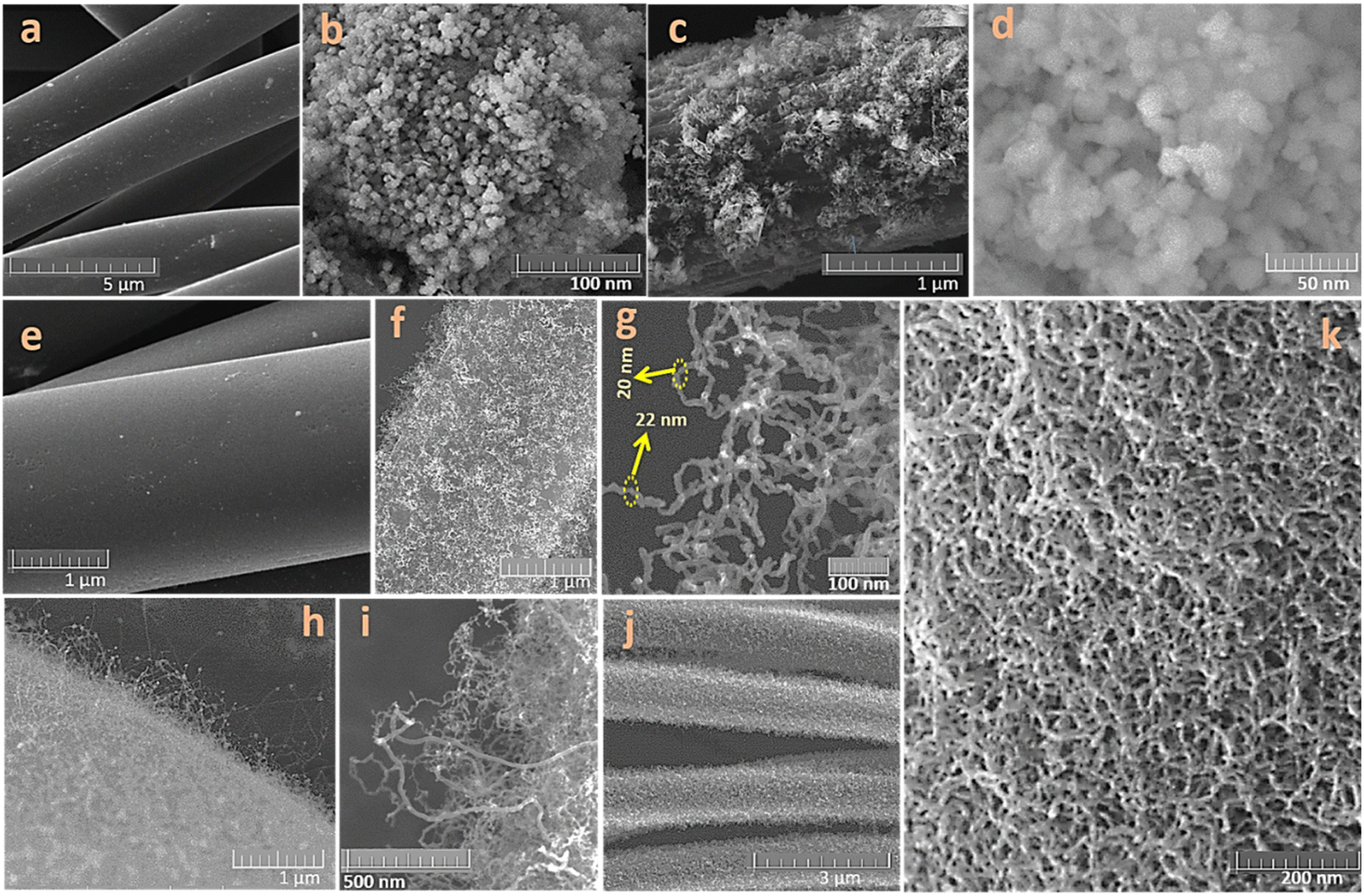 | ||
| Fig. 2 The SEM micrographs of carbon fabrics that were used as flexible support to deposit LRMNO nanoparticles (a and e). The SEM micrographs of the LRMNO nanoparticles were prepared by the solution route (b). The SEM micrographs of directly spray-coated LRMNO@CC at different magnifications (c and d). The SEM micrographs of the CVD-grown CNTs wrapped on the surface of carbon fabrics as 3D vertical arrays at different magnifications (f–h). SEM micrographs of spray-coated LRMNO@CNT-CC at different magnifications (i–k). | ||
The Li-rich manganese nickel oxides can assume different phases, and it is hard to get hold of an electrochemically active phase owing to the extensive Li/Ni disorder or structural changes due to the impurities.23–25 The preparation of a stable Li-rich electrochemically active phase with two Li transfer events is highly challenging due to degradation in their structure after the initial Li intercalation–deintercalation process.16 The parent compound, Li2MnO3, with C2/m monoclinic structure has attracted attention due to its superior theoretical capacity of 459 mA h g−1. Unfortunately, the Li2MnO3 material could not achieve a profound electrochemically active phase due to its high voltage for activation, irreversible capacity loss due to the structural degradation, and Jahn–Teller distortion by the migration of TM ions over the long run.24 The incorporation of Ni in Li2MnO3 mainly results in different solid solutions of multiple phases. The present study achieved the careful incorporation of Ni in Li2MnO3 by varying the concentration of TM ions and calcination temperatures. The preparation method and structural features are detailed in the ESI (ESI: S1, S2; Fig. S1†). The desired LRMNO phase, where the rudimentary structural features of Li2MnO3 were not disturbed, is shown in Fig. 3. The intricacy of the structural features of Li-rich cathode materials hampered attaining the correlation among the morphological features, structural defects, and its fading capacity/voltage.26 The careful Ni incorporation in Li2MnO3 offers different phases and stoichiometry with different TM ion concentrations and temperatures. The desired LRMNO powder prepared by the solution route in the present study did not hamper the rudimentary XRD pattern (Fig. 3a) of the parent compound. The pattern resolved using the TOPAS software (TOPAS Version-3, Bruker AXS) exhibited a layered monoclinic structure with a C2/m space group (Fig. 3b). Most of the previous attempts report that Ni incorporation results in severe structural modifications in the basic XRD pattern of Li2MnO3. Contrary to previous observations, Ni incorporation in Li2MnO3 generates a similar stacking pattern as shown by the resolved structures in Fig. 3b–f. The atomic arrangement along the b–c plane exhibits the stacking of the Li-rich layer, oxygen layer, and the TM (+excess Li) ions in the ABC–ABC pattern. As in Li2MnO3, the TM layer incorporates some excess Li and anti-sites to maintain the structure, however, in a lesser number as compared with in the parent structure.27 The atomic arrangement has been portrayed in Fig. 3c and d. Here, the charge neutrality and the structural integrity were maintained by some oxygen vacancies as indicated in Fig. 1(f). The oxygen redox activities and its associated TM diffusions are considered to be the major bottleneck in improving the electrochemical activities of the LRMO cathode materials.5,6,12 The surface oxygen defects can alleviate the oxygen redox activities and TM ion diffusion in LRMO cathodes.5,12,28 These vacancy points are mainly associated with alternate Ni stacking layers, aiding the facile Li-ion movement in this LRMNO phase. Ni incorporation also results in changes in the oxidation state of some of the Mn ions, which also contributes to the stability of the structure by maintaining charge neutrality. Here, analogous to the parent Li2MnO3, a prominent peak arises along the (131) crystallographic plane.29Fig. 3e shows the atomic arrangement along the crystallographic planes (131) and (001). The patterns resolved and the atomic arrangements ascertain that there is no hampering in the rudimentary layered geometry of the Li-rich parent compound Li2MnO3.
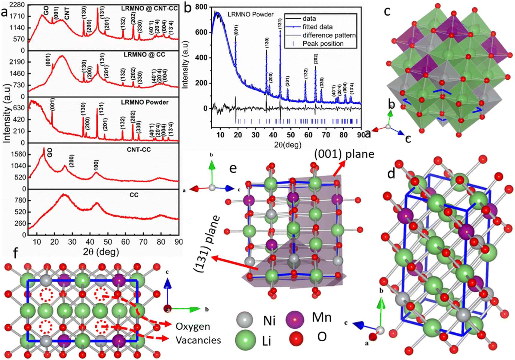 | ||
| Fig. 3 The XRD patterns of carbon fabrics, CNT wrapped carbon fabrics, and LRMNO powder prepared by the solution route, LRMNO@CC, and LRMNO@CNT-CC (a). The TOPAS-resolved XRD pattern of the LRMNO nano-powder sample (b). The polygonal (c) and ball and stick (d) models for the atomic arrangement of the LRMNO pattern. The atomic arrangement along the crystallographic plane (131) and (001) directions (e). The atomic alignment in the LRMNO powder along the b–c plane (f) (the dotted circle indicates oxygen vacancies). | ||
The XRD pattern of the bare carbon fabrics and the CNT-wrapped carbon fabrics, LRMNO@CC and LRMNO@CNT-CC, were included in Fig. 1a. The carbon fabrics maintain the inherent humps of amorphous carbon content around 2θ = 25 and 44°. Surprisingly, the CVD-grown CNT assume a sharper peak in this region, along with an additional peak at 2θ = ∼11°. This advocates the presence of more crystalline domains in the CVD-grown CNT-wrapped carbon fabrics.30,31 The peak around 2θ = 11° indicates the presence of crystalline graphene oxide (GO) derived from the carbon components of the fabrics, along with CNT growth.32 The highly ordered domains of the CNT and the GO components form the backbone of a 3D network for the wrapping of LRMNO particles onto the surface. The LRMNO@CC and LRMNO@CNT-CC also maintain the basic structure of the powder pattern with the peaks derived from CC and CNT derivatives. The carbon surface has been identified as a strategy to improve electronic conductivity and structural integrity for long-term cycling in Li-rich cathode materials.21 The peculiar properties of CNTs with exceptional crystalline domains of carbon suggest that they can act as a unique antenna reservoir for the supply of plasmons and excitons on the surface upon electromagnetic excitation.31 Here the morphologically robust CVD-grown CNTs on the surface of carbon fabrics provide a synergistic interaction with the LRMNO nanoparticles. The uniform distribution of carbon and the TM elements, Mn and Ni, on the surface of LRMNO@CC and LRMNO@CNT-CC has been exemplified from the EDX mapping as shown in Fig. 4a–d. To differentiate LRMNO particles attached to the surface of vertical CNTs grown on CC, the elemental mapping of bare CNT-CC has been included in the ESI (ESI: S.3.1 & Fig. S3†). Fig. 4a and b shows the uniform wrapping of LRMNO nanoparticles all over the surface of the 3D vertically aligned CVD-grown CNTs without any agglomeration; this arrangement is perceptible from the uniform signals in the elemental mapping. The LRMNO nanoparticles exhibit a relatively similar concentration of TM elements (Li2(Mn0.5Ni0.5)O3) in the desired composition with exceptional electrochemical properties. The LRMNO@CC and the LRMNO@CNT-CC samples maintain this concentration after wrapping the nanoparticles on the CNT/CC surface, which is evident from the TM element ratio (Ni/Mn ratio) calculated from the elemental analysis of this sample. The detailed elemental composition ratios of the TM elements are included in the ESI (ESI: S.4 and Table S1†).
 | ||
| Fig. 4 The SEM micrographs and their corresponding elemental mapping for LRMNO@CNT-CC (a and b) and LRMNO@CC (c and d), respectively. The Raman spectra of the D and G peaks of the carbon fabrics and CVD-grown CNT-carbon fabrics (e). The Raman spectra of LRMNO@CC and LRMNO@CNT-CC at low-frequency regions (up to 1000 cm−1) (f). The Raman spectra of the D and G peaks in LRMNO@CC and LRMNO@CNT-CC samples (g). The resolved XPS spectra of different elements Mn (h), Ni(i), O (j), and C (k) for LRMNO nano-powder. | ||
The Raman shifts at 1345 and 1580 cm−1 were assigned to the D and G lines of the carbon fabrics, and the CVD-CNT-grown carbon fabrics are shown in Fig. 4(e). The D and G lines for the LRMNO@CC and LRMNO@CNT-CC samples have been compared in Fig. 4(g). The disorder-induced phonon mode of the sp3 hybridised carbon content (D-line) was very prominent in the CC and LRMNO@CC as compared to the vibrational line G originating from the stretching mode of the sp2 hybridised carbon atoms.20 The CVD-grown CNT carbon fibrils delivered deeply graphitised (crystalline) carbon content contrary to the bare carbon fibrils. This was plausible from the percentage of crystalline carbon content calculated from the integral area of the D and G peaks of LRMNO@CC and LRMNO@CNT-CC samples (Table 1). Even though the intensity ratio IG/ID in both the samples was comparable, the area under the peak G and the percentage of the graphitised (crystalline) content of carbon calculated from the integral area under the peak showed that the CVD-grown 3D vertical CNT delivered (around 48%) highly graphitised carbon content (ESI. S5†). The prominent D and G lines and the absence of radial breathing mode (RBM) signal in LRMNO@CNT-CC and the bare CNT-CC samples verify that the CVD-grown nanotubes were the multiwalled type CNTs (m-WCNTs; the CNTs cited in the whole passage dealt with m-WCNTs, not the S-WCNTs).33,34 Sharp peaks at ∼630 cm−1 in both samples originate from the M–O vibrational bonds (A1g) of (Mn/Ni)–O6 octahedra layer formed as an alternative to the Li-rich layer in LRMNO C2/m phase as depicted in Fig. 4f. The low-intensity peak at low frequencies (around 330 cm−1), can be ascribed to the stretching mode vibrations of Li–O6 octahedra.20 The absence of sharp peaks at 400, 250, and 270 cm−1 verifies the absence of the Li2Mn2O4 tetragonal spinal phase35 as a solid solution with LRMNO particles. The absence of a peak at 490 and 605 cm−1 verifies the absence of LiNi1/3Mn2/3O2 phase.36 Rather than the peak around 605 cm−1, as in LiNi1/3Mn2/3O2, the TM vibrational peak had been shifted to 630 cm−1 due to the presence of innumerable Mn3+, along with Mn4+, in the prepared LRMNO sample.
| Sample | I G/ID | Integral area of G band (A(G)) | Integral area of D band (A(D)) | FWHM | Crystalline percentage of carbon (in%) = A(G)/[A(G) + A(D)] | |
|---|---|---|---|---|---|---|
| D | G | |||||
| LRMNO@CNT-CC | (576.40/580.35) 0.993 | 5283.37 | 9838.80 | 79.27 | 79.03 | 34.94 |
| LRMNO@CC | (557.30/563.10) 0.988 | 7267.88 | 7759.67 | 125.69 | 73.64 | 48.36 |
The XPS analysis of the sample ascertained the presence of Mn3+ and Mn4+ in the LRMNO nanoparticles. The extensive Mn3+ play a pivotal role in improving the structural stability and electrochemical properties of the LRMNO nanoparticles. The XPS survey spectrum (ESI: Fig. S7†) shows the presence of Ni, Mn, O and C. Li has a very low relative sensitivity factor and is overlapped with Mn 3p peak in XPS spectra. The Ni 2p3/2 was fitted with a single bonding state of Ni2+ centred on 855 eV (Fig. 4i).28 The shoulder peak at higher binding energy belonged to the Ni satellite feature. The Mn 2p3/2, spectrum was fitted with two sets of multiplet-split components for Mn3+ and Mn4+ bonding states (ESI: Fig. S6†), the sum of these multiples is shown in Fig. 4h.37 The peaks around 285 eV originate from carbon species (e.g. CO2 or organic molecules) adsorbed on the surface of the sample (Fig. 4k). In the O1s spectrum (Fig. 4j), the peak at ∼528 eV originated from oxygen in the LRMNO.13 The peak at 530 eV originated from adsorbed species on the surface like CO2 or H2O. The presence of oxygen vacancies can improve the stability and reduce oxygen gas evolution during long-term cycling in LRMNO electrode material.6
The clear details on the morphological features of the LRMNO nano-powder and the single isolated fabrics of LRMNO@CC and LRMNO@CNT-CC samples were recorded using HR-TEM and STEM analysis (Fig. 5a–n). The TEM, HR-TEM, and corresponding SAED patterns of the LRMNO nano-powder are shown in Fig. 5a–d. Fig. 5a and b shows the TEM micrographs of the uniformly arranged nanoparticles (the particles are highlighted with yellow in Fig. 5b). The well-resolved lattice fringes of 0.475 nm in the HR-TEM micrograph shown in Fig. 5c correspond to the prominent (001) crystal plane of LRMNO nanoparticles.29 The FFT image and the corresponding lattice fringe profile have been included in Fig. 5d and e. Nevertheless, the LRMNO exhibits a layered structure with Li and TM order, and it bears some defects in its structure due to Ni incorporation and O vacancies as evidenced by the resolved XRD pattern and corresponding atomic structures, which slightly increases the lattice spacing.6,13 Furthermore, the TM arrangement over the alternative Li-rich layer also changes due to the Li/Mn and Li/Ni mixing in the structure.6 Still, the lattice profile follows the basic layered structure of monoclinic C2/m with the regular repetition of the TMs layer, the O layer and the Li-rich layer.38 The crystal region corresponding to the resolved structural pattern of the LRMNO nanoparticle is marked in Fig. 5f and g. It is quite difficult to image the LRMNO (wrapped on CNT-CC or CC fabrics) to elucidate its morphological features using the TEM technique. The STEM was utilised to probe the features of a single string of LRMNO nano-particle-wrapped 3D-CVD-CNT on carbon fabrics and the LRMNO-wrapped carbon fabrics without CNT support for the first time. Even though the study bears some limitations to obtaining a high magnification image (beyond 500 nm), we could nonetheless properly probe the uniform growth of 3D-vertical CNTs on carbon fabrics (ESI: S.3.2, Fig. S4†) and the LRMNO particles wrapped on the surface of vertical CNTs (Fig. 5k and l & ESI: Fig. S5†). The LRMNO nanoparticles uniformly arranged on the surface of carbon fabrics (without any CNT support) are visible from the bright and dark field STEM images provided with different magnifications in Fig. 5h–j. Fig. 5k and l depicts the STEM micrographs of LRMNO@CNT-CC. The bright and dark field images depict the LRMNO nanoparticle wrapped on the surface of vertical 3D-CNTs arranged on the surface of the fabrics. The STEM micrographs of the 3D-CNT array grown on the surface of a single fabric string and additional images for LRMNO@CNT-CC at different magnifications are provided as ESI (ESI: S.3.2†).
 | ||
| Fig. 5 The TEM micrographs of the LRMNO nano-powder (a and b). The HR-TEM (c), corresponding to the FFT image (d). Lattice annular fringes (e) of the LRMNO nanoparticles. The crystal region (f) corresponding to the resolved structural pattern (g) of the LRMNO nanoparticles. The STEM images at different field magnifications of single-string carbon fabrics of LRMNO@CC (h–j) and LRMNO@CNT-CC (k and l), respectively. | ||
The electrochemical properties of LRMNO@CC and LRMNO@CNT-CC are depicted in Fig. 6. The galvanostatic charge–discharge plots of LRMNO@CC and LRMNO@CNT-CC show similar profiles within the voltage range of 3.5–4.9 V. Here the high voltage profile up to 4.9 V was recorded to verify the electrochemical activity of Ni2+ and Mn3+/4+ ions.39 The LRMNO@CNT-CC (Fig. 6d) remit an initial capacity of 218 mA h g−1, while the LRMNO@CC (Fig. 6a) gives a capacity of 180 mA h g−1 in its 5th stable cycle, which is superior to the capacity derived from the LRMNO powder sample (ESI: S7, S8†). The capacity versus cycle number and corresponding coulombic efficiencies for the initial 100 cycles at the current rate of 1C (1C = 250 mA g−1) are portrayed in Fig. 6b and e for LRMNO@CC and LRMNO@CNT-CC, respectively.40 The capacity derived from the sample at different current rates is compared in Fig. 6c and f. Even though the capacity of the sample during the initial cycles sustained without much fading for both LRMNO@CC and LRMNO@CNT-CC samples, the LRMNO@CNT-CC sample exhibited outstanding rate capability as shown in Fig. 6f. The LRMNO@CC could not cycle beyond the current rate of 10C while the LRMNO@CNT-CC maintained a capacity even at 25C.
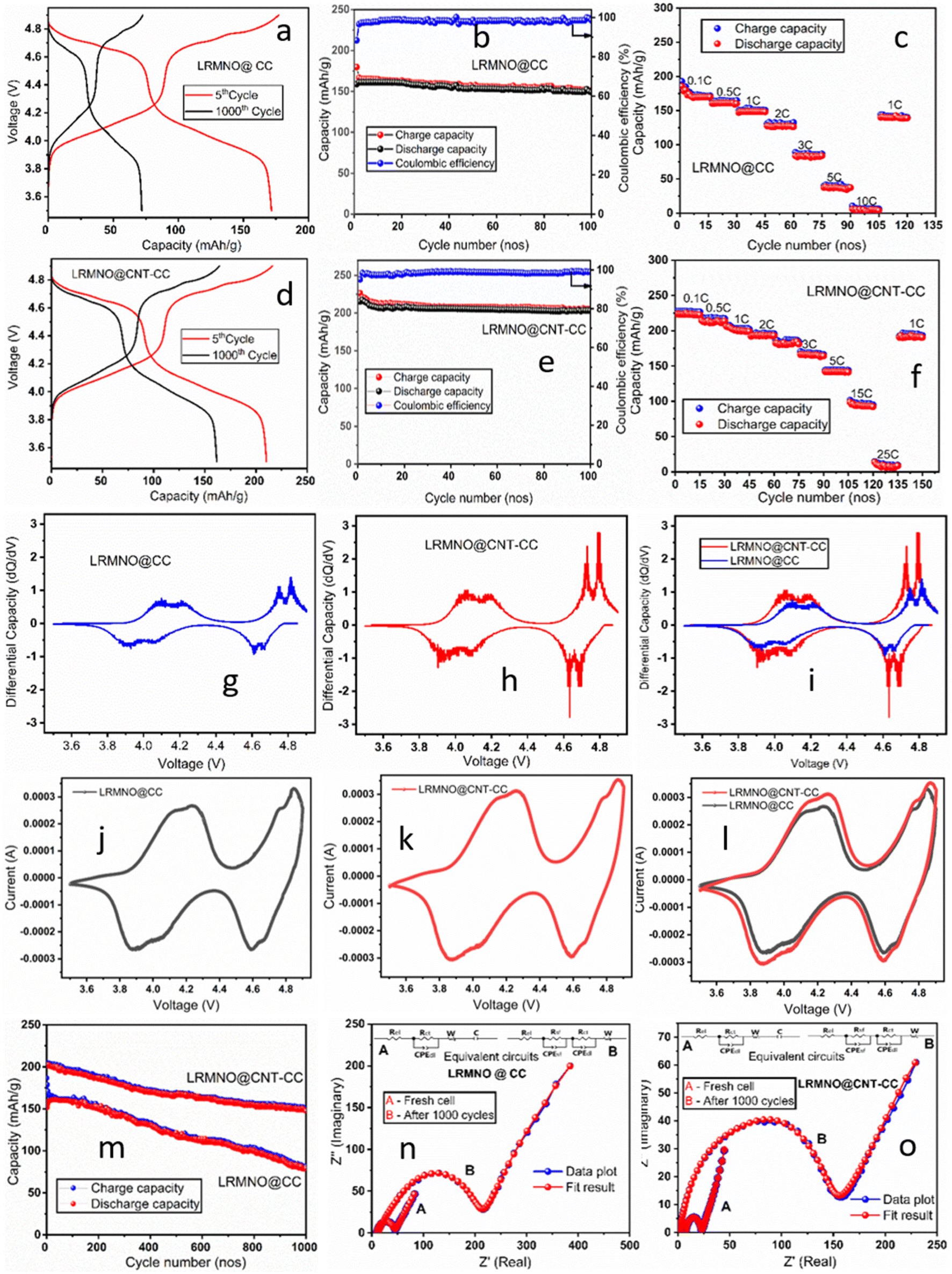 | ||
| Fig. 6 Comparison of the electrochemical properties of the LRMNO@CC and LRMNO@CNT-CC samples. The galvanostatic charge–discharge profile for LRMNO@CC (a) and LRMNO@CNT-CC (d) samples within the voltage range of 3.5 to 4.9 V. The capacity versus cycle number for the initial 100 charge–discharge cycles and corresponding coulombic efficiencies for LRMNO@CC (b) and LRMNO@CNT-CC (e) samples, respectively. The rate sustainability of LRMNO@CC (c) and LRMNO@CNT-CC (f) samples at different current rates from 0.1 to 25C. The differential capacity versus voltage plots for the LRMNO@CC (g) and LRMNO@CNT-CC (h) samples and a combined plot (i) at the 100th cycle. The cyclic voltammetric plots for the LRMNO@CC (j) and LRMNO@CNT-CC (k) samples and a combined plot (l) at a scan rate of 0.1 mV. The long-term cyclability of LRMNO@CC and LRMNO@CNT-CC samples (m) up to 1000 cycles at a 1C rate. The impedance plots of the LRMNO@CC (n) and LRMNO@CNT-CC (o) samples were recorded and compared for the fresh cell after completing 1000 charge–discharge cycles. | ||
The very high rate sustainability of the LRMNO@CNT-CC sample was derived from the highly porous nature of the 3D-vertically grown CNT support for the Li-rich cathode material. The highly crystallised CNT content provided by the CVD-grown CNTs and the presence of highly ordered appended GO components provided a synergistic interaction with LRMNO nano-particles wrapped uniformly on its surface.31 This synergistic interaction provided advanced capacity and superior rate capability in LRMNO@CNT-CC samples as compared to LRMNO@CC. The long-term cyclability of the samples has been compared in Fig. 6m at the 1C rate, which substantiated the aforementioned observations. The galvanostatic charge–discharge profile of the sample during the 1000th cycle is compared in Fig. 6a and d. The 3D LRMNO@CNT-CC, when cycled within the voltage range of 3.5–4.9 V, exhibited a high capacity of up to 208 mA h g−1 (after 10 initial cycles) at a 1C rate and a surprising capacity retention of 91% after 200 cycles and 71% after 1000 cycles. The results were highly promising as far as the Li-rich TM cathode materials were concerned. Table 2 presents a comparison of the electrochemical properties of LRMNO@CNT-CC with the recently reported top-notch Li-rich cathode materials. The structural integrity and morphology form the major milestones in accomplishing high capacity and high rate performances in Li-rich cathode material. The high voltage, high rate capability, and exceptional rate sustainability of the LRMNO@CNT-CC samples were derived from the nanoarchitecture of the vertical 3D-CNT supports grown by the CVD technique on carbon fabrics.

|
Fig. 6g and h shows the differential capacity versus the voltage plots for LRMNO@CC and LRMNO@CNT-CC, respectively, during the 100th cycle. Both plots follow a similar profile with two pairs of electrochemical redox peaks within the voltage range of 3.5 to 4.9 V. The redox pair around the voltages, 4.05 and 4.18 V, and their corresponding peaks in the negative region of 3.93 and 4.08 V are derived from Mn3+/4+ to Mn4+/5+ redox process. The prominent differential peak in this region ascertains the presence of substantial Mn3+ in the LRMNO sample prepared by the solution route. This is highly promising and different from the LiNi0.5Mn1.5O4- and Li2MnO3-type parent materials. It has been reported that the poor electrochemical activity of LRMO parent material emanates from the trivial Mn3+ component and poor electrochemical activity of the Mn4+ ions.16,24 When cycled up to 4.9 V, the sample exhibits two prominent redox peaks at ∼4.72/4.63 V and ∼4.79/4.68 V, which are ascribed to the redox reactions of Ni2+/Ni3+ and Ni3+/Ni4+. This ascertains the point at which LRMNO@CNT-CC and LRMNO@CC exhibit two prominent Li-ion transfer redox processes during the charge–discharge cycles. This is promising and off-beat from the prevailing outlook. The differential capacity plots of the LRMNO@CNT-CC and LRMNO@CC samples have been compared in Fig. 6l. The corresponding cyclic voltammetric plots at the scan rate of 0.1 mV are recorded in Fig. 6j and k for the LRMNO@CC and LRMNO@CNT-CC, respectively, to corroborate the results. The CV plots endorse the presence of an intensive redox couple within the voltage range of 3.9–4.15 V, which is derived from the Mn3+/Mn4+ redox events. Some previous reports have reported a redox peak in this region, but the highly intensive peaks present in the sample in this study establish the presence of an ample amount of Mn3+ in the sample, which facilitates faster redox events to facilitate two Li+/electron transfer.16,26,48 The absence of the redox signal at ∼4.5 V, as reported in the case of parent LRMO material, suggests the absence of O loss and related complex O redox activities in the prepared LRMNO sample.16 The labile O vacancies induced by Ni incorporation made the sample structurally stable during the charge–discharge cycle without further O loss through O dimerisation.16 The more integral area covered by the LRMNO@CNT-CC sample was derived from the capacity captured from the highly graphitised carbon network of CVD-grown CNT and GO components present in the sample. The synergistic interaction between the 3D vertical carbon network and the wrapped LRMNO nanoparticles contributes to the excess capacity and stable cycling of the sample.
The impedance plots for the LRMNO@CC and LRMNO@CNT-CC samples were recorded and compared for the fresh cell and after completing 1000 charge–discharge cycles (Fig. 6n and o). Impedance plots were fitted using the Z-view software, and the most fitted equivalent circuit model was provided as inset pictures in Fig. 6n and o. The fit parameters and the resistance values were provided in Table 3. The LRMNO@CNT-CC sample exhibited low impedance value in the fresh cell and in the cells after long-term cycling. The total resistance and charge transfer resistance values were low in the LMNO@CNT-CC sample, when compared with the LRMNO@CC samples. The highly porous nano-architecture of CNT-CC support provided facile Li-ion intercalation through the surface, sustaining long-term cycling as well.
| Sample | Fresh cell | After 1000 cycles | |||
|---|---|---|---|---|---|
| R el (Ω) | R ct (Ω) | R el (Ω) | R sf (Ω) | R ct (Ω) | |
| LRMNO@CC | 9.75 | 33.78 | 13.76 | 79.32 | 125.5 |
| LRMNO@CNT-CC | 7.39 | 14.42 | 3.45 | 53.75 | 90.98 |
The Li-rich cathode material, LRMNO@CC and LRMNO@CNT-CC, was tested for its full-cell performance by preparing a pouch cell as shown in Fig. 7. Fig. 7g–l shows different electrode layers and the scheme for the preparation of the flexible pouch cell, which was used to light an LED device. Mn3O4 was chosen as the counter electrode. Detailed information for the preparation of the flexible Li-ion pouch cell using LRMNO@CNT-CC and LRMNO@CC cathode materials is included in the ESI (ESI: S1†). The Mn3O4 nanoparticles prepared by the solution route were spray coated on the surface of the carbon fabrics using a spray coater. The spray-coated MO nanoparticles (MO@CC) exhibited a high capacity of 510 mA h g−1 at a 1C rate. The galvanostatic charge–discharge profile for the 5th and 150th cycle (Fig. 7a) and the capacity versus cycle plots for the initial 150 cycles (Fig. 7b) show the novel electrochemical performances of the MO@CC electrodes within the voltage range 0.005–3 V. The comparison of the galvanostatic charge–discharge profiles of the individual electrodes and the full-cell configurations of the LRMNO@CC and LRMNO@CNT-CC samples are displayed in Fig. 7c and d. The first cycle charge–discharge profiles at different current rates for the full cell in MO/LRMNO@CNT-CC configurations are portrayed in Fig. 7e. The comparison of the capacity versus cycle number plots of MO/LRMNO@CNT-CC and MO/LRMNO@CC for the initial 200 cycles are plotted in Fig. 7f. The figure shows that the flexible full-cell configurations exhibit stable charge–discharge cycles with less fading in the CVD-CNT supports as compared with the LRMNO coated on carbon fabrics without any support. The electrochemical performance of the prepared MO/LRMNO@CNT-CC full-cell configurations at different bending and folding states are portrayed in Fig. 7m and n. The galvanostatic charge/discharge profile and the resultant capacity versus cycling plots at different bending and folding modes of the operation attest that there are only negligible capacity variations in the prepared 3D flexible Li-rich cathode materials. This, in turn, underlines that only trivial stress and strain forces develop within the cell during its extremely flexible modes of operation. The capacity of the MO/LRMNO@CNT-CC configurations at steady state and at different bending/folding modes are tabulated in Table 2. The studies show that the LRMNO nanoparticles prepared by the solution route wrapped on highly graphitised carbon fabrics can be easily adapted for flexible battery configurations to yield superior electrochemical properties.
 | ||
| Fig. 7 The galvanostatic cycling profiles for the 5th and 500th cycle of Mn3O4 spray-coated on CC (MO@CC) electrode (anode) for a full-cell assembly (a). The specific capacity versus cycle number plots for the MO@CC electrode (b). A comparison of the galvanostatic charge–discharge profiles of the cathodes, anodes, and the full cells with MO@CC/LRMNO@CC (c) and MO@CC/LRMNO@CNT-CC (d). The galvanostatic charge–discharge profiles at different current rates for the MO@CC/LRMNO@CNT-CC pouch cell (e). A comparison of specific capacity versus cycle number plots in MO@CC/LRMNO@CC and MO@CC/LRMNO@CNT-CC pouch cells for the initial 200 cycles (f). A schematic of the different electrode (g–i) layers of fabric electrode and separator in the pouch cell assembly (j) and the resulting highly flexible, bendable pouch cells (k) using Li-rich cathode materials to light an LED (l). The galvanostatic charge/discharge profile of the MO@CC/LRMNO@CNT-CC at different bending and folding state at 1C (m). The cycling performance of the MO@CC/LRMNO@CNT-CC flexible cell at different bending and folding states (the inset shows different bending and folding modes) at 1C (n). | ||
The long-term cycling performance with minimum capacity fading of the LRMNO nanoparticle, when wrapped on 3D-CNT grown by the CVD method, was assimilated by the synergistic interaction between the highly graphitised carbon component and the LRMNO nanoparticles. The 3D vertical CVD-CNT support provides the additional capacity and the highly porous surfaces for the facile Li-ionic movement within the electrodes. The role of the 3D-CNT support could be verified by the post-cycling examination of the long-term cycled batteries. The long-term cycled batteries were resolved inside the glove box with special care and the LRMNO@CNT-CC and LRMNO@CC fabrics were detached to record the XRD, SEM, and Raman analysis. The XRD pattern of the LRMNO@CNT-CC (Fig. 8a) samples prevailed over most of the peaks specific to the monoclinic C2/m space group, while LRMNO@CC (Fig. 8c) predominated only the major peaks. The peak intensity was also lesser as compared to the XRD pattern of LRMNO@CNT-CC. The SEM micrographs of the LRMNO@CNT-CC and LRMNO@CC samples are compared in Fig. 8b and d. The LRMNO nanoparticles wrapped on the CNTs were preserved even after 1000 charge–discharge cycles as shown in Fig. 8d. The 3D texture clearly maintained the porous morphology of the sample over long-term cycling, clearly establishing that the sample was free of cracking related to O evolution in its structure and morphology.2 The structural integrity and morphological robustness of the LRMNO@CNT-CC samples were derived from the highly graphitised carbon content provided by the CVD-grown 3D vertical CNT support and the GO carbon network.
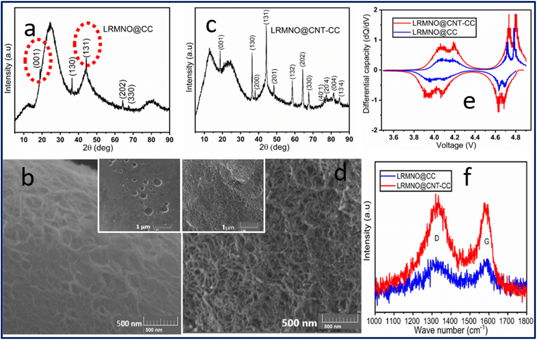 | ||
| Fig. 8 The post-cycling analysis of the XRD patterns of LRMNO@CC (a) and LRMNO@CNT-CC (c) samples. The SEM micrographs of the LRMNO@CC (b) and LRMNO@CNT-CC (d) samples after 1000 cycles. A comparison of the differential capacity versus voltage curves for LRMNO@CNT-CC and LRMNO@CC samples at the 1000th cycle (e). Post-cycling analysis of the D and G lines of Raman spectra of LRMNO@CNT-CC and LRMNO@CC samples (f). | ||
The post-cycling analysis of the carbon-related D and G spectral lines in the Raman spectra (Fig. 8f) revealed that the integral area covered by the D and G lines of LRMNO@CNT-CC samples was higher than the LRMNO@CC samples. The percentage of crystalline (graphitised) carbon content present in the LRMNO@CNT-CC samples (40.10%), was higher than that in the LRNMO@CC (32.55%) samples. More details on the post-cycling analysis of the D and G lines in the Raman spectra and the calculation of crystalline carbon content have been included in the ESI (ESI: S5 & Table S2†). It must be noted that the ratio of the percentage of crystalline components prevailed without much fading after the 1000 charge–discharge intercalations in both samples. This clearly substantiates the synergistic interaction of carbon from the 3D-vertical CNTs and the fabrics with the Li-rich cathode material, providing structural integrity, highly porous nature, and sustainable electrochemical properties of the LRMNO nanoparticles. The differential capacity versus voltage plots at the 1000th charge–discharge cycles of the LRMNO@CNT-CC and LRMNO@CC samples are portrayed in Fig. 8e. The redox peak-pair around the 3.8–4.1 V derived from the Mn3+/4+ to Mn4+/5+ redox process is comparatively less prominent in the LRMNO@CC samples, while the LRMNO@CNT-CC maintains prominent peaks in this region. This clearly establishes the fact that the concentration of the Mn3+ component in the LRMNO@CC samples is considerably less as compared to the LRMNO@CNT-CC samples.
The study reveals that the structural integrity and nano-architecture of the LRMNO@CNT-CC cathode material with highly crystallised 3D vertical CNT surfaces along with the GO carbon network can effectively improve its capacity and long-term cyclability with minimum fading. The schematic representation (Fig. 9) portrays the role of a highly porous 3D-CVD-CNT carbon network and the structural integrity of LRMNO nanoparticles wrapped on its surface in improving the electrochemical properties and facile Li-ion intercalation of the LRMNO nanoparticles. The pre-occupied anion vacancies due to the O defects created by Ni incorporation, adjacent to the Li+ sites, create enough free space for the facile Li-ion movement through the Li-rich layer and TM/Li occupied layer.16 Here, owing to the utilisation of O as a stable structural unit by maintaining charge neutrality using Mn and Ni ions with flexible valence,16 the O vacancies stabilise the structure, instead of triggering O redox activities. This, in turn, alleviates TM hopping due to the Jahn–Teller effect, resulting in superior electrochemical stability over long-term cycling in the prepared Li-rich cathode material. The O vacancies prevent O dimerisation and evolution of O during the Li insertion–deinsertion process, which helps to maintain the structural integrity of the LRMNO nanoparticles over long-term cycling. The strong Mn2+/Mn4+ redox couple has been noticed here as the first of its kind, along with the Ni2+/Ni4+ redox couple, in single Li-rich cathode materials. It completely eliminates the O redox activities in the LRMNO material and stabilises it to retain a high rate of sustainability without structural degradation.26,48 This, in turn, facilitates two Li+/2e− transfers during the single electrochemical cycling without any O loss from the structural unit.16 Along with this, the 3D carbon network (as shown in the schematic diagram Fig. 9) aids in the facile Li-ion movement and escalates an avalanche of surface electrons.31 The assimilated high capacity of the LRMNO@CNT-CC clearly ascertains the point at which the careful control of structure by systematic incorporation of Ni ions and size reduction (along with the incorporation of nano-architecture of the 3D vertical CNT as a surface for wrapping LRMNO nanoparticles) become highly desirable to drive multiple Li-ion transfer events in Li-rich TM cathode materials.
 | ||
| Fig. 9 A schematic representation of the synergistic interaction of CVD-grown 3D-CNT network and the LRMNO particle: (a) LRMNO wrapped on q 3D vertical CNT grown on CC. (b) Magnified image of a single CNT string wrapped with LRMNO particles. (c) LRMNO nanoparticles, and (d) unit-cell arrangement of the LRMNO nanoparticles. | ||
The Li-excess high voltage cathode materials are reckoned as one of the most decisive classes of cathodes for the quantum leap of next-generation Li-ion battery technology. The poor capacity retention and structural degradation of this material is a predicament for its wide-scale industrial implementations. The present study provided a detailed strategy to forefront the Li-excess Li2MnO3 cathode material by the combined utilisation of morphological modification using 3D carbon networks and the incorporation of Ni element, while paying special attention to upholding the structure. The high electrochemical activities with two Li+/e− transfer in the 3D-LRMNO@CNT-CC cathode materials pave the way to developing high-performance Co-free, structurally sensitive, Li-rich Mn-based cathode materials for their strategical advancement to achieve stabilised electrochemical properties in flexible Li-ion batteries.
3. Conclusion
The Li-rich cathode material, lithium manganese nickel oxide was prepared by a solution route without disturbing its rudimentary structural features to procure high capacity and striking rate capabilities. The LRMNO particles supported by the 3D vertical CVD-grown CNTs exhibited high capacity and outstanding rate capabilities. The structural integrity and the morphological robustness of the LRMNO@CNT-CC samples helped them acquire stable long-term cycling and high current sustainability. The spray-coated 3D LRMNO@CNT-CC, when cycled within the voltage range of 3.5–4.9 V, exhibited a high capacity of up to 220 mA h g−1 (after 5 initial cycles) at 1C rate and a surprising capacity retention of 91% after 200 cycles and 71% after 1000 cycles. The strong Mn2+/Mn4+ redox events, along with the Ni2+/Ni4+ redox couple, facilitated two Li+/2e− transfers during single electrochemical cycling without oxygen loss from the structural unit. The synergistic interaction between the highly graphitised CNT and LRMNO nanoparticles improved and stabilised the electrochemical cycling capabilities of the highly sensitive Li-rich cathode materials, which was evident from the lower electrochemical performances of the LRNMO coated without any CNT support. The exceptional electrochemical activities of the LRMNO@CNT-CC cathode materials paved the way for developing high-performance Co-free, Li-rich, Mn-based cathode materials to scale up its global industrial implementations as a high-capacity and high-voltage cathode material. Moreover, the study elaborates on stabilizing the microstructure and morphology of highly sensitive Li-rich cathode materials to achieve superior electrochemical performances.Author contributions
K. P. A. and Z. S. conceived the idea and designed the experiments. K. P. A. carried out the synthesis, structural characterisation, and electrochemical analysis. L. D. performed the FE-SEM, STEM, and Raman analysis of the samples. V. M. collected and analysed the XPS pattern. K. P. A. wrote the manuscript. S. P. and L. D. contributed to manuscript preparation and experimental works. Z. S. and K. P. A. received the funding to coordinate the work.Declaration of competing interest
The authors declare that they have no known competing financial interests or personal relationships that could have appeared to influence the work reported in this paper.Conflicts of interest
There are no conflicts to declare.Acknowledgements
K. P. A. was supported by the European Structural and Investment Funds; OP RDE funded the project, ‘CHEMFELLS IV’ (No. CZ.02.2.69/0.0/0.0/ 20_079/0017899). The project was supported by the ERC-CZ program (project LL2101) from the Ministry of Education Youth and Sports (MEYS).References
- W. Li, E. M. Erickson and A. Manthiram, Nat. Energy, 2020, 5, 26–34 CrossRef CAS.
- J. Huang, B. Ouyang, Y. Zhang, L. Yin, D.-H. Kwon, Z. Cai, Z. Lun, G. Zeng, M. Balasubramanian and G. Ceder, Nat. Mater., 2023, 22, 353–361 CrossRef CAS PubMed.
- B. Li, G. Rousse, L. Zhang, M. Avdeev, M. Deschamps, A. Abakumov and J.-M. Tarascon, Energy Environ. Sci., 2023, 16, 1210–1222 RSC.
- K. P. Abhilash, P. Nithyadharseni, P. Sivaraj, D. Lakshmi, S. Agarwal, B. B. Mamba and Z. Sofer, in Solid State Batteries: Design, Challenges and Market Demands, ed. N. Palaniyandy, K. P. Abhilash and B. Nalini, Springer International Publishing, Cham, 2022, pp. 275–295, DOI:10.1007/978-3-031-12470-9_10.
- D.-H. Seo, J. Lee, A. Urban, R. Malik, S. Kang and G. Ceder, Nat. Chem., 2016, 8, 692–697 CrossRef CAS PubMed.
- Z. Cai, S. Wang, H. Zhu, X. Tang, Y. Ma, D. Y. W. Yu, S. Zhang, G. Song, W. Yang, Y. Xu and C. Wen, J. Colloid Interface Sci., 2023, 630, 281–289 CrossRef CAS PubMed.
- N. Voronina, Y.-K. Sun and S.-T. Myung, ACS Energy Lett., 2020, 5, 1814–1824 CrossRef CAS.
- M. M. Thackeray, S.-H. Kang, C. S. Johnson, J. T. Vaughey, R. Benedek and S. A. Hackney, J. Mater. Chem., 2007, 17, 3112–3125 RSC.
- L. Xiong, M. Sun, Y. Xu, X. Du and X. Xiao, Solid State Ionics, 2018, 325, 170–175 CrossRef CAS.
- J. Yang, F. Cheng, X. Zhang, H. Gao, Z. Tao and J. Chen, J. Mater. Chem. A, 2014, 2, 1636–1640 RSC.
- Y. Liu, X. Fan, Z. Zhang, H.-H. Wu, D. Liu, A. Dou, M. Su, Q. Zhang and D. Chu, ACS Sustainable Chem. Eng., 2019, 7, 2225–2235 CrossRef CAS.
- G.-H. Lee, V. W.-h. Lau, W. Yang and Y.-M. Kang, Adv. Energy Mater., 2021, 11, 2003227 CrossRef CAS.
- R. Yu, M. N. Banis, C. Wang, B. Wu, Y. Huang, S. Cao, J. Li, S. Jamil, X. Lin, F. Zhao, W. Lin, B. Chang, X. Yang, H. Huang, X. Wang and X. Sun, Energy Storage Mater., 2021, 37, 509–520 CrossRef.
- Y.-K. Sun, D.-J. Lee, Y. J. Lee, Z. Chen and S.-T. Myung, ACS Appl. Mater. Interfaces, 2013, 5, 11434–11440 CrossRef CAS PubMed.
- S.-T. Myung, F. Maglia, K.-J. Park, C. S. Yoon, P. Lamp, S.-J. Kim and Y.-K. Sun, ACS Energy Lett., 2017, 2, 196–223 CrossRef CAS.
- H. Chen and M. S. Islam, Chem. Mater., 2016, 28, 6656–6663 CrossRef CAS.
- M. Fichtner, Phys. Chem. Chem. Phys., 2011, 13, 21186–21195 RSC.
- N. Mahmood and Y. Hou, Adv. Sci., 2014, 1, 1400012 CrossRef PubMed.
- A. Karuthedath Parameswaran, J. Azadmanjiri, N. Palaniyandy, B. Pal, S. Palaniswami, L. Dekanovsky, B. Wu and Z. Sofer, Nano Energy, 2023, 105, 107994 CrossRef CAS.
- W. Zhao, L. Xiong, Y. Xu, H. Li and Z. Ren, J. Power Sources, 2017, 349, 11–17 CrossRef CAS.
- F. Ning, H. Shang, B. Li, N. Jiang, R. Zou and D. Xia, Energy Storage Mater., 2019, 22, 113–119 CrossRef.
- A. Choi, K. Palanisamy, Y. Kim, J. Yoon, J.-H. Park, S. W. Lee, W.-S. Yoon and K.-B. Kim, J. Alloys Compd., 2014, 591, 356–361 CrossRef CAS.
- X. Meng, S. Dou and W.-l. Wang, J. Power Sources, 2008, 184, 489–493 CrossRef CAS.
- T. E. Mabokela, A. C. Nwanya, M. M. Ndipingwi, S. Kaba, P. Ekwere, S. T. Werry, C. O. Ikpo, K. D. Modibane and E. I. Iwuoha, J. Electrochem. Soc., 2021, 168, 070530 CrossRef CAS.
- S. Dou, J. Solid State Electrochem., 2013, 17, 911–926 CrossRef CAS.
- J. Serrano-Sevillano, M. Reynaud, A. Saracibar, T. Altantzis, S. Bals, G. van Tendeloo and M. Casas-Cabanas, Phys. Chem. Chem. Phys., 2018, 20, 23112–23122 RSC.
- X. Wen, C. Yin, B. Qiu, L. Wan, Y. Zhou, Z. Wei, Z. Shi, X. Huang, Q. Gu and Z. Liu, J. Power Sources, 2022, 523, 231022 CrossRef CAS.
- Y. Cai, L. Ku, L. Wang, Y. Ma, H. Zheng, W. Xu, J. Han, B. Qu, Y. Chen, Q. Xie and D.-L. Peng, Sci. China Mater., 2019, 62, 1374–1384 CrossRef CAS.
- X. Dong, Y. Xu, S. Yan, S. Mao, L. Xiong and X. Sun, J. Mater. Chem. A, 2015, 3, 670–679 RSC.
- A. Sivakumar, S. S. Jude Dhas, T. Pazhanivel, A. I. Almansour, R. S. Kumar, N. Arumugam, C. J. Raj and S. A. M. B. Dhas, Cryst. Growth Des., 2021, 21, 1617–1624 CrossRef CAS.
- P.-H. Ho, D. B. Farmer, G. S. Tulevski, S.-J. Han, D. M. Bishop, L. M. Gignac, J. Bucchignano, P. Avouris and A. L. Falk, Proc. Natl. Acad. Sci. U. S. A., 2018, 115, 12662–12667 CrossRef CAS PubMed.
- S. Woo, Y.-R. Kim, T. D. Chung, Y. Piao and H. Kim, Electrochim. Acta, 2012, 59, 509–514 CrossRef CAS.
- A. Dobrzańska-Danikiewicz, D. Łukowiec, D. Cichocki and W. Wolany, Arch. Mater. Sci. Eng., 2013, 64, 103–109 Search PubMed.
- A. I. López-Lorente, B. M. Simonet and M. Valcárcel, Analyst, 2014, 139, 290–298 RSC.
- H.-S. Park, S.-J. Hwang and J.-H. Choy, J. Phys. Chem. B, 2001, 105, 4860–4866 CrossRef CAS.
- S. Liu, Z. Liu, X. Shen, W. Li, Y. Gao, M. N. Banis, M. Li, K. Chen, L. Zhu, R. Yu, Z. Wang, X. Sun, G. Lu, Q. Kong, X. Bai and L. Chen, Adv. Energy Mater., 2018, 8, 1802105 CrossRef.
- E. S. Ilton, J. E. Post, P. J. Heaney, F. T. Ling and S. N. Kerisit, Appl. Surf. Sci., 2016, 366, 475–485 CrossRef CAS.
- M. Gu, I. Belharouak, A. Genc, Z. Wang, D. Wang, K. Amine, F. Gao, G. Zhou, S. Thevuthasan, D. R. Baer, J.-G. Zhang, N. D. Browning, J. Liu and C. Wang, Nano Lett., 2012, 12, 5186–5191 CrossRef CAS PubMed.
- J. C. Knight and A. Manthiram, J. Mater. Chem. A, 2015, 3, 22199–22207 RSC.
- J. R. Croy, J. S. Park, F. Dogan, C. S. Johnson, B. Key and M. Balasubramanian, Chem. Mater., 2014, 26, 7091–7098 CrossRef CAS.
- L. Bao, L. Wei, N. Fu, J. Dong, L. Chen, Y. Su, N. Li, Y. Lu, Y. Li, S. Chen and F. Wu, J. Energy Chem., 2022, 66, 123–132 CrossRef CAS.
- W. Cheng, J. Ding, Z. Liu, J. Zhang, Q. Liu, X. Wang, L. Wang, Z. Sun, Y. Cheng, Z. Xu, Y. Lei, J. Wang and Y. Huang, Chem. Eng. J., 2023, 451, 138678 CrossRef CAS.
- R. A. House, L. Jin, U. Maitra, K. Tsuruta, J. W. Somerville, D. P. Förstermann, F. Massel, L. Duda, M. R. Roberts and P. G. Bruce, Energy Environ. Sci., 2018, 11, 926–932 RSC.
- J. Lee, D. A. Kitchaev, D.-H. Kwon, C.-W. Lee, J. K. Papp, Y.-S. Liu, Z. Lun, R. J. Clément, T. Shi, B. D. McCloskey, J. Guo, M. Balasubramanian and G. Ceder, Nature, 2018, 556, 185–190 CrossRef CAS PubMed.
- S.-J. Kim, M.-C. Kim, D.-H. Kwak, D.-M. Kim, G.-H. Lee, H.-S. Choe and K.-W. Park, J. Power Sources, 2016, 304, 119–127 CrossRef CAS.
- X. Cao, J. Sun, Z. Chang, P. Wang, X. Yue, J. Okagaki, P. He, E. Yoo and H. Zhou, Adv. Funct. Mater., 2022, 32, 2205199 CrossRef CAS.
- H. Wang, F. Liu, R. Yu, Z. Xiao, Z. Zhu, L. Zhou and J. Wu, Nano Energy, 2022, 100, 107439 CrossRef CAS.
- X. Dong, Y. Xu, L. Xiong, X. Sun and Z. Zhang, J. Power Sources, 2013, 243, 78–87 CrossRef CAS.
Footnote |
| † Electronic supplementary information (ESI) available. See DOI: https://doi.org/10.1039/d3ta01209c |
| This journal is © The Royal Society of Chemistry 2023 |