
A compact interphase involving a reversible redox couple stabilizes a 4.6 V LiCoO2 cathode†
Junbo
Zhang
ab,
Chengwu
Liu
c,
Haikuo
Zhang
b,
Ruhong
Li
b,
Ling
Lv
b,
Di
Lu
b,
Shuoqing
Zhang
b,
Xuezhang
Xiao
 b,
Shujiang
Geng
a,
Fuhui
Wang
a,
Tao
Deng
d,
Lixin
Chen
be and
Xiulin
Fan
*b
b,
Shujiang
Geng
a,
Fuhui
Wang
a,
Tao
Deng
d,
Lixin
Chen
be and
Xiulin
Fan
*b
aShenyang National Laboratory for Materials Science, Northeastern University, Shenyang, 110819, China
bState Key Laboratory of Silicon Materials, School of Materials Science and Engineering, Zhejiang University, Hangzhou 310027, China. E-mail: xlfan@zju.edu.cn
cDepartment of Chemical Engineering, Shanghai Electrochemical Energy Devices Research Center, Shanghai Jiao Tong University, Shanghai 200240, China
dDepartment of Chemical and Biomolecular Engineering, University of Maryland, College Park, MD, USA
eKey Laboratory of Advanced Materials and Applications for Batteries of Zhejiang Province, Hangzhou 310013, China
First published on 21st March 2023
Abstract
LiCoO2 (LCO), as a commercialized cathode material for batteries, suffers from severe structural instability and capacity fading when charged to high voltages (>4.5 V) due to oxygen release, Co dissolution, and subsequent crack formation/electrolyte decomposition. Herein, we constructed a compact SOx-rich cathode electrolyte interphase (CEI) involving a reversible SO42−/S2O32− redox couple via an additive (bis(4-fluorophenyl) sulfone)-assisted electrolyte, thus improving the electrochemical performance of graphite‖LCO cells at high voltage. Bis(4-fluorophenyl) sulfone was found to adsorb on the LCO cathode and form a reversible SO42−/S2O32− redox couple, which alleviated oxygen release by continuous reduction/oxidation during the charging/discharging process, thus inhibiting the decomposition of the electrolyte. The designed electrolyte endows a 4.6 V Li‖LCO cell and 4.55 V graphite‖LCO cell with high capacity retention of 88% over 300 cycles and 96% over 150 cycles, respectively. The compact CEI involving a reversible redox couple strategy provides new insights into electrolyte design for high-voltage cathodes and overcomes the limit toward the development of high-energy-density batteries.
 Xiulin Fan | Dr Fan received PhD degrees from Zhejiang University. From 2013 to 2017, he worked as a Postdoctoral Research Associate at the University of Maryland College Park (UMD) and was then promoted to an Assistant Research Scientist in 2017 at UMD. Since August 2019, Dr Xiulin Fan has been a professor at the School of Materials Science and Engineering, Zhejiang University. His research interest is electrolytes and interphases in high-energy batteries. He has been recognized as a highly cited researcher by Clarivate since 2020. |
Introduction
The demand for a breakthrough in the energy density of lithium-ion batteries (LIBs) has urged us to explore more aggressive chemistries.1,2 An effective approach to increase the energy output is to increase the operating voltages,3,4 especially for LCO, which is the dominant cathode material in current LIBs for consumer electronics due to its high volumetric energy density.5–7 To date, the charge cut-off voltage in commercial LCO cathodes is limited to below 4.35 V (vs. Li+/Li), yielding a discharge capacity of ∼165 mA h g−1, which is still far from the theoretical maximum (274 mA h g−1).8–10 More reversible capacity can be achieved by elevating the charge cut-off voltage.11,12 However, a substantial increase in capacity achieved at higher charge cut-off voltage (>4.5 V vs. Li+/Li) would come at the expense of rapid decay of capacity and efficiency due to serious structural and interfacial instability issues.13–15 At a cut-off voltage of >4.35 V (vs. Li+/Li), oxygen redox (O2− ↔ O1−) starts to contribute capacity (O 2p orbitals hybridize with Co 3d orbitals).16 The mobile peroxide ion O1− with a lower migration barrier is easier to escape from a metal oxide particle in the form of O2,17,18 resulting in oxygen vacancies and transition metal co-migration.19–21 Moreover, a phase transition from the O3 hexagonal phase to the hybridized O1–O3 hexagonal phase (denoted as the H1–3 phase) occurs at around 4.55 V.10 Such phase transition leads to a large anisotropic expansion and contraction along the c and a axes, respectively and eventually induces crack generation and particle pulverization.6,22,23 Apart from the O loss and structural collapse in the cathode, the electrode–electrolyte interfacial instability is another critical issue, which is always aggravated at high charge cut-off voltage. The undesirable electrolyte decomposition triggered by high-valence Co/O24 causes large interfacial impedance and severe gas generation, leading to continuous capacity degradation of the cell. Such irreversible oxygen loss/Co dissolution, bulk structure deterioration, and unstable electrode–electrolyte interfaces jeopardize the practical application of LCO at high voltage. Therefore, the key to achieving highly reversible LCO LIBs for high-voltage operation is to sustain the stability of bulk LCO and electrode–electrolyte interfaces.To cater to the long-cycling stability of the LCO cathode at high charge cut-off voltage, a myriad of methods have been developed. Surface coating25–27 can effectively maintain the structural integrity of cathode materials and reduce the undesirable side reactions at electrode–electrolyte interfaces. However, artificial surface coating usually leads to a high interfacial resistance and poor self-healing capability, limiting the performance enhancement. Doping some inactive elements,8,28,29 such as Ti, Mg, and Al, is another effective strategy to stabilize the LCO cathode. Yet, the introduced inactive elements lowered the specific capacity and energy density of the cathode. Electrolyte engineering30–32 has been demonstrated to be promising and effective for the improvement of electrochemical performances of LCO, since it possesses the ability to spontaneously tailor a highly protective CEI that can inhibit the electrolyte decomposition and minimize cathode degradation. Specifically, the use of sacrificial additives to assist the electrolyte33–35 is considered one of the most effective and economical approaches. These additives aid in generating a stable and mechanically robust CEI layer on cathodes, which improves the electrochemical performance, safety, and lifespan of the battery. Representative examples of the additives include the compounds containing –C![[triple bond, length as m-dash]](https://www.rsc.org/images/entities/char_e002.gif) N−,36,37, −B–O−,38,39 and –SO2−33,40 functional groups, which participate in the formation of a protective CEI layer. However, since each additive has unique functions that improve battery performance, their use may introduce negative impacts while enhancing the targeted performance.34 Furthermore, identifying additives that can effectively address the multiple challenges of LCO cathodes at ultra-high voltages (>4.6 V) remains a significant challenge.
N−,36,37, −B–O−,38,39 and –SO2−33,40 functional groups, which participate in the formation of a protective CEI layer. However, since each additive has unique functions that improve battery performance, their use may introduce negative impacts while enhancing the targeted performance.34 Furthermore, identifying additives that can effectively address the multiple challenges of LCO cathodes at ultra-high voltages (>4.6 V) remains a significant challenge.
Herein, we report bis(4-fluorophenyl) sulfone (BFS) as the multi-functional additive to (i) stabilize the LCO/electrolyte interface and (ii) improve the electrochemical performance of graphite‖LCO cells at high voltage. Post-mortem characterization analysis and theoretical simulations show that BFS tends to adsorb on the LCO surface and form a SOx-rich CEI involving a reversible SO42−/S2O32− redox couple during the charging/discharging process. The reversible SO42−/S2O32− redox couple helps alleviate oxygen release, thus suppressing transition metal (TM) dissolution and cathode surface reconstruction within the cathode, effectively mitigating cathode crack formation and electrolyte degradation. The designed electrolyte, namely 1 M lithium hexafluorophosphate (LiPF6) in ethylene carbonate/dimethyl carbonate (EC/DMC, 1![[thin space (1/6-em)]](https://www.rsc.org/images/entities/char_2009.gif) :1 v/v)+0.5 wt% BFS abbreviated as BE + BFS, effectively promoted the electrochemical performance of a 4.6 V Li‖LCO cell and 4.55 V graphite‖LCO cell, with record-high capacity retentions (CRs) of 88% over 300 cycles and 96% over 150 cycles, respectively, which are almost 23% higher than those with pure BE. In addition, a realistic 1 Ah-level 4.55 V graphite‖LCO pouch cell under lean electrolyte conditions of 2 g (Ah)−1 also achieves a high CR of 94% after 100 cycles. This work sheds light on a rational and practical electrolyte design strategy via a cost-effective additive approach to form a stable interfacial layer and protect the structural stability of cathode materials.
:1 v/v)+0.5 wt% BFS abbreviated as BE + BFS, effectively promoted the electrochemical performance of a 4.6 V Li‖LCO cell and 4.55 V graphite‖LCO cell, with record-high capacity retentions (CRs) of 88% over 300 cycles and 96% over 150 cycles, respectively, which are almost 23% higher than those with pure BE. In addition, a realistic 1 Ah-level 4.55 V graphite‖LCO pouch cell under lean electrolyte conditions of 2 g (Ah)−1 also achieves a high CR of 94% after 100 cycles. This work sheds light on a rational and practical electrolyte design strategy via a cost-effective additive approach to form a stable interfacial layer and protect the structural stability of cathode materials.
Results and discussion
Characterization of the electrolytes
The affinity of several additives and solvents to the LCO cathode was calculated by density functional theory (DFT) methods. As shown in Fig. 1a and ESI Fig. 1,† BFS preferentially adsorbs on the surface of LCO by virtue of its lower adsorption energy (−2.46 eV), compared to EC (−1.39 eV), DMC (−1.27 eV), and fluoroethylene carbonate (FEC, −1.20 eV). The highest occupied molecular orbital (HOMO) energy and lowest unoccupied molecular orbital (LUMO) energy levels (Fig. 1b) show that BFS possesses a higher HOMO energy (−7.53 eV) compared to traditional solvents EC (−8.49 eV) and DMC (−8.21 eV), indicating that BFS tends to be oxidized at a lower voltage than EC/DMC and contribute to CEI formation, dictating the behavior of the electrolyte on the surface of a highly catalytic cathode.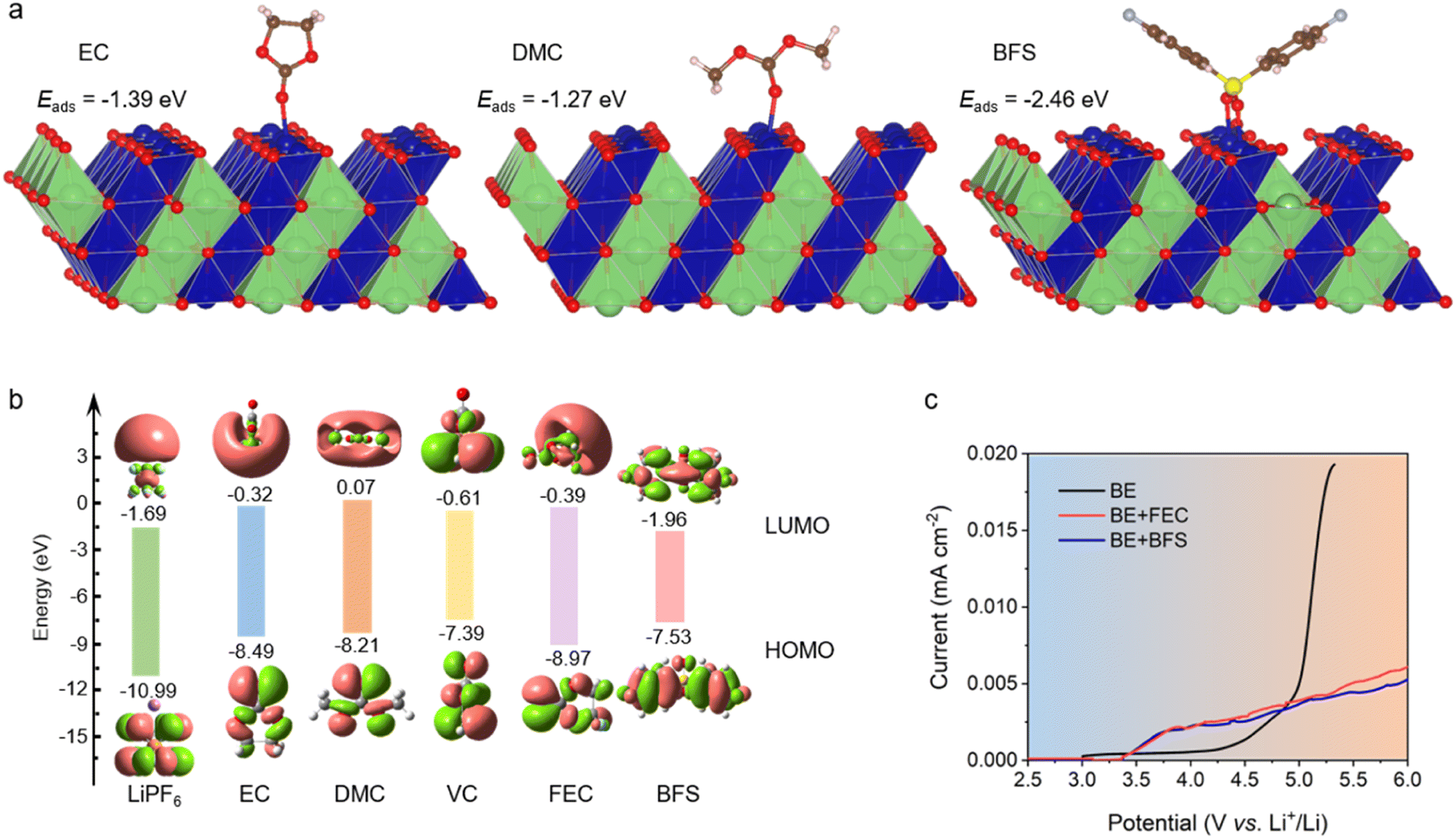 | ||
| Fig. 1 Electrolyte design and performance. (a) Adsorption energies of EC, DMC, and BFS on the (104) surface of LCO. (b) Calculated HOMO and LUMO energies of EC, DMC, VC, FEC, BFS, and LiPF6. (c) Oxidation stability of different electrolytes evaluated by LSV at a scanning rate of 1 mV s−1. | ||
The optimum ratio of BFS (0.5%) in the resulting electrolyte (BE + BFS) was systematically screened to achieve a low interfacial resistance and a long cycle life (ESI Fig. 2†). Meanwhile, such small dosage of additives shows no significant effect on the physicochemical properties of the electrolyte (ESI Table 1†). 1 M LiPF6/EC–DMC (1:1 v/v) abbreviated as BE and 1 M LiPF6/EC–DMC (1:1 v/v)+1 wt% FEC abbreviated as BE + FEC were used as the reference electrolytes. The oxidation stability of the designed electrolyte was preliminarily investigated by linear sweep voltammetry (LSV). Fig. 1c illustrates the exponential increase in oxidation current observed in BE at 4.2 V, which is attributed to its inferior anodic stability. The addition of either FEC or BFS has a positive impact on the oxidation stability of the electrolyte. Notably, the anodic current of BE + BFS is only 1/5 of that observed in BE at a high potential of 5.2 V, despite the fact that it starts to increase due to the decomposition of BFS at 3.5 V. The significantly suppressed oxidation current in the BE + BFS electrolyte suggests that the preferential decomposition of BFS effectively passivates the cathode surface, thereby inhibiting further decomposition of the electrolyte at high voltage. This result establishes a promising foundation for the application of the BE + BFS electrolyte in high voltage batteries.
Compatibility between the electrodes and the electrolyte
To investigate the compatibility between the BE + BFS and aggressive high-voltage LCO cathodes, the electrochemical performances of Li‖LCO half cells were evaluated with a charge cut-off voltage of 4.6 V. As shown in Fig. 2a, all Li‖LCO cells exhibit almost the same initial specific capacity of ∼220 mA h g−1 in the three formation cycles at 0.1C (1C = 274 mA g−1). The Li‖LCO cell with BE shows continuous capacity fading after activation cycles and retains 80% of its original capacity with an obvious increase in voltage hysteresis (ESI Fig. 3†) after 175 cycles. This is attributed to the electrolyte decomposition on the catalytic cathode at high voltage and the accumulation of side products. The BE + FEC delivers better compatibility with the high-voltage LCO cathode. However, the Li‖LCO cell with the BE + FEC maintains only 236 cycles before reaching 80% CR. In contrast, the BE + BFS endows the 4.6 V Li‖LCO cell with a CR of 88% over 300 cycles, with a high average coulombic efficiency (CE) of >99.7% and less voltage decay (Fig. 2b). Meanwhile, the BE + BFS also endows the Li‖LCO cell with excellent rate capacity, which was demonstrated by the results based on two different charge/discharge protocols (Fig. 2c and 4 C/0.2–10C for charge/discharge; ESI Fig. 4,† 0.2–10C/0.2C for charge/discharge). All Li‖LCO cells deliver almost similar specific capacities at discharge rates of 0.1C (∼220 mA h g−1) and 0.2C (∼175 mA h g−1). When the discharge rate was gradually increased to 10C, a fast capacity decay occurred in the Li‖LCO cell with BE and a limited specific capacity of ∼118 mA h g−1 was obtained. Moreover, the reversible capacity faded rapidly even when the discharge rate was reduced back to 0.1C, manifesting that the LCO cathode cycled with BE suffers from severe damage at such high current density. In comparison, the Li‖LCO cell with the BE + BFS performs significantly better at high discharge rates by delivering a specific capacity 1.2 times as high as BE at 10C (144 mA h g−1). The specific capacity then recovers to ∼220 mA h g−1 and remains stable once the discharge rate is decreased back to 0.1C, manifesting that the LCO cathode remains intact.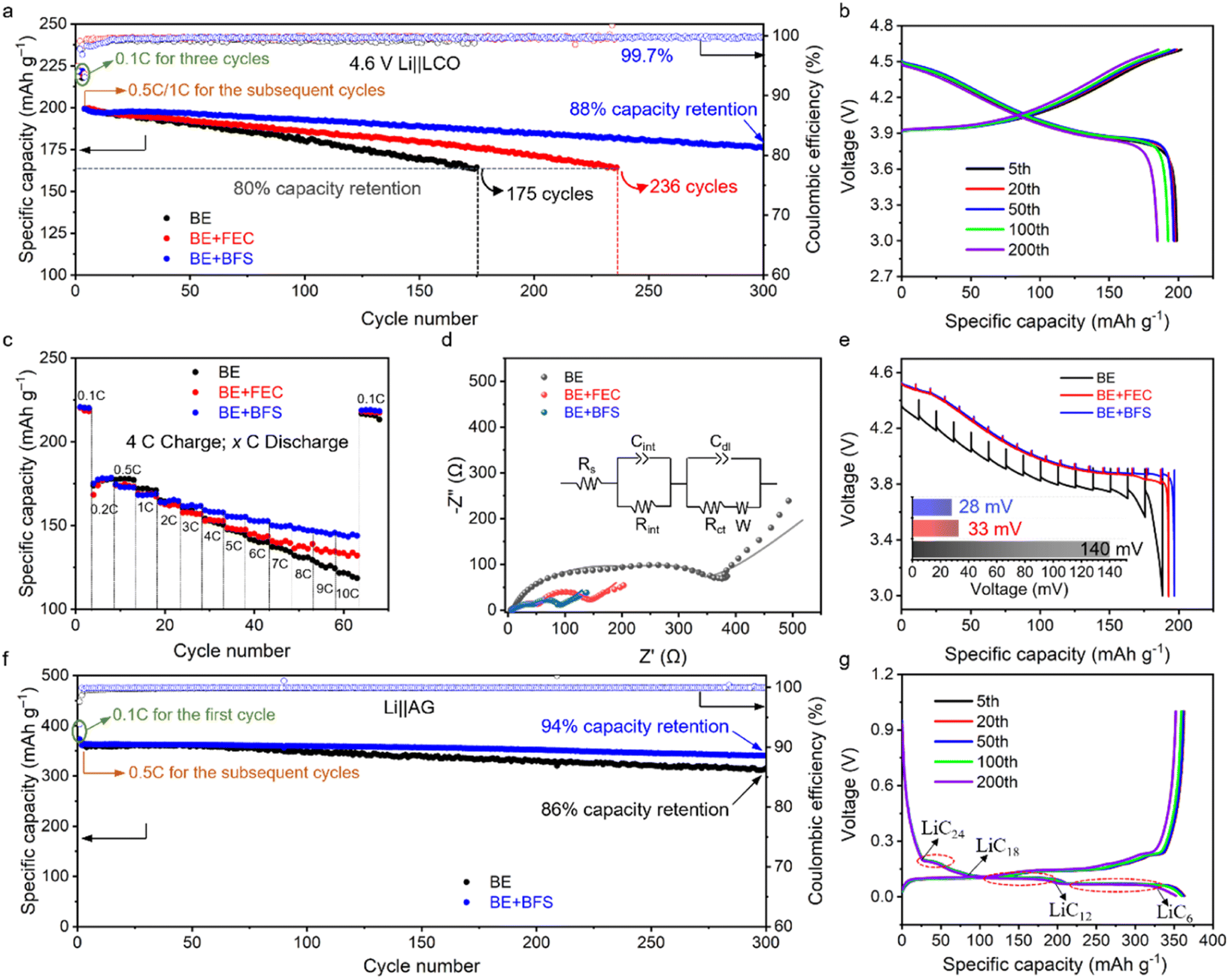 | ||
| Fig. 2 Electrochemical compatibility between different electrolytes and LCO/graphite electrodes. (a) Cycling stability of 4.6 V Li‖LCO half cells with different electrolytes at 0.5C charge/1C discharge after 3 activation cycles at 0.1C between 3 V and 4.6 V. (b) Galvanostatic charge–discharge curves of 4.6 V Li‖LCO cells using the BE + BFS. (c) Rate performance of 4.6 V Li‖LCO cells using different electrolytes at 4C charge and varied discharge rates after 3 activation cycles at 0.1C. (d) EIS spectrum of Li‖LCO cells after 300 cycles in different electrolytes. The inset shows a fitted equivalent circuit. (e) Discharge voltage profiles of GITT measurements on the cells after 100 cycles at 0.5C charge and 1C discharge rates. (f) Cycling stability of Li‖graphite half cells with different electrolytes at 0.5C charge/0.5C discharge after 3 activation cycles at 0.1C. (g) Galvanostatic charge–discharge curves of Li‖graphite cells using the BE + BFS electrolyte. | ||
The electrochemical performance of the Li‖LCO cell is closely associated with the ionic conductivity and electrode voltage polarization. The resistance of the Li‖LCO cell after 300 cycles in BE is found to be one order of magnitude higher than the uncycled Li‖LCO cell, as measured by electrochemical impedance spectroscopy (EIS)41 (Fig. 2d, ESI Fig. 5 and Table 2†). The large interfacial resistance (Rint, 90.1 Ω) and charge transfer resistance (Rct, 360.5 Ω) after 300 cycles indicate a poor ionic conductive nature of the BE-derived interface and sluggish kinetics during the Li+ intercalation/de-intercalation. Notably, the Rint in the BE + BFS (28.6 Ω) is only one third of that observed in BE, and the Rct is reduced by 85% (54.2 Ω), indicating the presence of a highly conductive SEI and fast charge-transfer kinetics in the BE + BFS. Based on the results of the galvanostatic intermittent titration technique (GITT), a severe polarization of ∼140 mV can be observed for the cell with the LCO cathode cycled with BE (Fig. 2e). In contrast, the average voltage loss in the BE + BFS is 80% lower than the former, demonstrating a minimum impedance growth in the LCO cathode cycled in the BE + BFS, in good accordance with the EIS results shown in Fig. 2d.
An ideal electrolyte should not only be stable against oxidation on high-voltage cathode surfaces, but also guarantee stable and reversible Li+ intercalation/de-intercalation on the graphite anode. As shown in Fig. 2f, g and ESI Fig. 6,† although BE ensures stable cycling of the Li‖graphite cell with 86% CR over 300 cycles, the BE + BFS presents better compatibility with the graphite anode, which endows the Li‖graphite cell with a high CR of 94% over 300 cycles and an average CE of 99.94%. There are three voltage plateaus observed at approximately 0.2 V, 0.11 V, and 0.08 V in Fig. 2g, which correspond to the sequential formation of multi-stage structures of the lithium graphite intercalation compound (LiCx). These structural transitions occur from LiC24 to LiC18, from LiC18 to LiC12, and from LiC12 to LiC6, respectively, as reported in previous literature.42 The charge–discharge curves in Fig. 2g confirm the stable Li+ intercalation/deintercalation into/from the graphite process ensured by the BE + BFS electrolyte. Therefore, the BE + BFS possesses outstanding anodic and cathodic stability and holds promise for ensuring stable operation of high-voltage LIBs.
Chemistry at the interphases
To further understand the stark difference in electrochemical performance, postmortem analysis of the LCO microstructure was conducted using scanning electron microscopy (SEM) images with top views (Fig. 3a–c) and the interphase was scrutinized by high-resolution transmission electron microscopy (HRTEM) (Fig. 3d–f). The LCO cathode cycled in BE develops a large number of cracks (highlighted by the white ovals in Fig. 3a) in the bulk particles, due to the huge volume expansions and stresses during Li+ intercalation/de-intercalation. These cracks tend to induce much severer electrolyte decomposition on the catalytic cathode surface and lead to a thick CEI (∼7 nm) (Fig. 3d), impeding the electrochemical performance of batteries. The BE + FEC (Fig. 3b and e) effectively keeps the LCO cathode intact and decreases the CEI layer to a thickness of 5 nm. Notably, the BE + BFS electrolyte forms an ultrathin and compact CEI layer of 3 nm on the LCO cathode surface (as shown in Fig. 3f), exhibiting excellent passivation ability. Although the difference in thickness is only 4 nm (compared with that formed in BE), the CEI formed in the BE + BFS is about 1/2 of the CEI formed in BE. This difference in thickness can have a significant impact on battery performance. A thin and compact CEI layer is crucial for efficient Li+ transportation and preventing cell polarization. This results in the LCO cathode being well-structured without obvious cracks (Fig. 3c). The thin CEI layer generated in the BE + BFS electrolyte also presents low Rint and Rct values, as demonstrated in ESI Fig. 7 and Table 3.† This contributes to favorable Li+ transport and charge-transfer properties, ensuring stable cycling of the Li‖LCO half-cell (Fig. 2a). Meanwhile, the post-mortem analysis conducted after different cycles in cells (ESI Fig. 8†) reveals that the electrode/electrolyte interface was sustained well in the cell with BE + BFS electrolyte once it was formed. The cathode stability during the Li+ intercalation/deintercalation process was characterized using the dQ/dV curves (ESI Fig. 9†). The reduced redox peaks with increased polarization for the LCO cathode cycled in BE electrolyte indicate the severe structural degradation and capacity loss caused by serious side reactions between the catalytic cathode and electrolyte at high voltages. In contrast, sharp redox peaks with mitigated polarization were observed in the LCO cathode cycled for 200 cycles in the BE + BFS electrolyte, verifying the well-maintained structure of LCO wrapped by an effective CEI layer.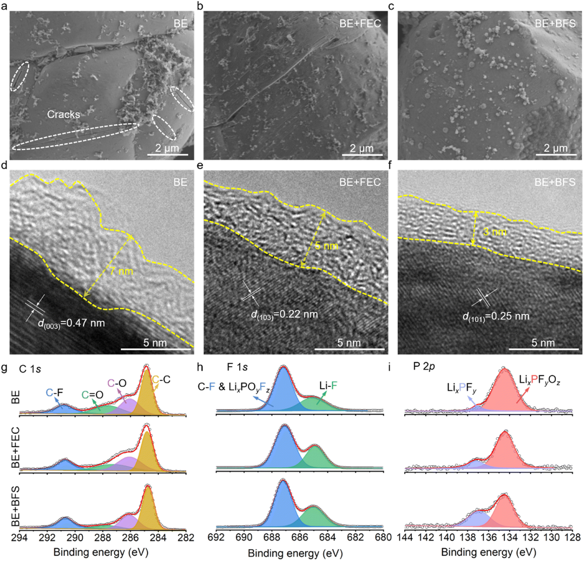 | ||
| Fig. 3 Characterization of LCO cathode cycles in different electrolytes. (a–c) Top views of SEM images of LCO cathodes cycled in BE (a), BE + FEC (b) and BE + BFS (c). (d–f) HRTEM images of LCO cathodes cycled in BE (d), BE + FEC (e) and BE + BFS (f). (g–i) XPS profiles of the LCO cathode surface after 100 cycles in different electrolytes. | ||
CEI chemical composition investigated by X-ray photoelectron spectroscopy (XPS) is shown in Fig. 3g–i. The LCO cathode cycled in BE shows strong intensity signals of C–F (290.8 eV), C![[double bond, length as m-dash]](https://www.rsc.org/images/entities/char_e001.gif) O (287.6 eV), C–O (286.1 eV), and C–C (284.8 eV) in C 1s spectra,43–45 suggesting a CEI rich in organic components. The addition of FEC significantly increases the LiF (685.6 eV in F 1s spectra) content in the CEI due to the decomposition of FEC, which is consistent with previous reports.46–48 The slight shift in the XPS results may be caused by the measurement errors of the instrument. Notably, the LCO cathode cycled in the BE + BFS shows dramatically decreased contents in C 1s spectra, implying that the addition of BFS effectively suppresses the decomposition of EC/DMC on the catalytic LCO cathode surface. Meanwhile, the increased LiF content in F 1s spectra manifests that an inorganic-rich CEI is formed in the BE + BFS, thus enhancing the stability of the cathode.
O (287.6 eV), C–O (286.1 eV), and C–C (284.8 eV) in C 1s spectra,43–45 suggesting a CEI rich in organic components. The addition of FEC significantly increases the LiF (685.6 eV in F 1s spectra) content in the CEI due to the decomposition of FEC, which is consistent with previous reports.46–48 The slight shift in the XPS results may be caused by the measurement errors of the instrument. Notably, the LCO cathode cycled in the BE + BFS shows dramatically decreased contents in C 1s spectra, implying that the addition of BFS effectively suppresses the decomposition of EC/DMC on the catalytic LCO cathode surface. Meanwhile, the increased LiF content in F 1s spectra manifests that an inorganic-rich CEI is formed in the BE + BFS, thus enhancing the stability of the cathode.
To uncover the mechanism for the enhanced electrochemical performance at ultra-high voltage, the sulfur and oxygen containing species were also characterized by XPS. As shown in the S 2p spectra (Fig. 4a), the two doublet peaks at 162.0 eV and 170.8 eV can be attributed to thiosulfate-type S2O32− and sulfate-type SO42−,49,50 respectively. The intensity of the SO42− peaks increases and then decreases during charging and discharging process, while the intensity of the S2O32− peaks decreases first and then increases. At 4.6 V, the intensity of SO42− and S2O32− reaches the maximum and minimum value (ESI Fig. 10†), respectively, suggesting that the reversible SO42−/S2O32− redox reaction occurs in each charge/discharge cycle. In the O 1s spectra (Fig. 4b), the peak located at 533.1 eV, 531.6 eV, 530.5 eV and 528.8 eV can be assigned to electrolyte oxidation species, carbonate species (CO32−), oxygen vacancies and lattice oxygen (O2−), respectively.51 The peak corresponding to the electrolyte oxidation increases/decreases on the subsequent charge/discharge process, and its maximum value appears at the highest charging voltage of 4.6 V. The intensity of electrolyte oxidation in the BE + BFS at a voltage of 4.6 V is greatly reduced compared with those in the BE and BE + FEC (Fig. 4c), demonstrating that the electrolyte decomposition at the LCO cathode is significantly suppressed by the addition of BFS. By combining the analysis of S 2p and O 1s spectra, it was found that this suppression effect may be due to the oxygen relieved by the reversible SO42−/S2O32− redox reaction. Furthermore, the lattice oxygen, as a precursor of strongly oxidizing O−/O22−, shows the weakest intensity in the BE + BFS (Fig. 4c), further verifying the above inferences. Such stable interface chemistry contributes to stabilization of the aggressive LCO cathode at 4.6 V and suppression of TM dissolution.52,53 As shown in (Fig. 4d), a triple-decrease in Co dissolution from 0.06 ppm to 0.02 ppm in the BE + BFS, measured by inductively coupled plasma mass spectrometry (ICP-MS), is achieved compared with BE.
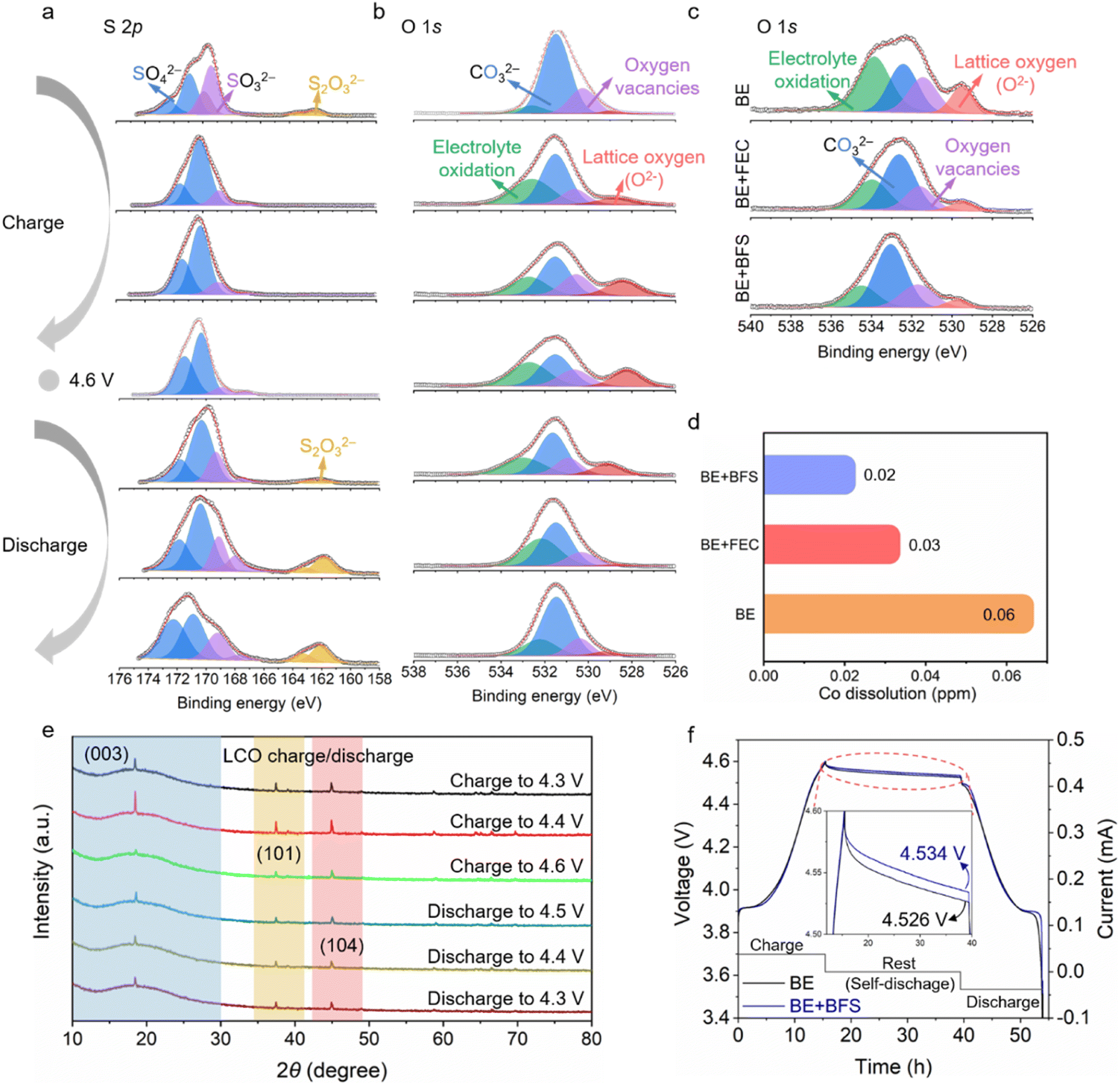 | ||
| Fig. 4 Structure and phase analysis of the LCO cathode. (a) S 2p XPS spectra of the LCO cathode cycled in the BE + BFS during the second charge/discharge process. (b) O 1s XPS spectra of the LCO cathode cycled in the BE + BFS during the second charge/discharge process. (c) O 1s XPS spectra of the LCO cathode cycled in different electrolytes. (d) Transition-metal (Co) dissolution determined by ICP-MS after 100 cycles in different electrolytes. (e) The ex situ XRD pattern evolution of the LCO cathode collected during the charge/discharge process with the BE + BFS at 0.1C. (f) The self-discharge curves of Li‖LCO cells using different electrolytes at 4.6 V. | ||
The structural evolution of the LCO cathode is strongly associated with cycling stability. The structural evolution monitored by ex situ XRD measurement (Fig. 4e and ESI Fig. 11†) confirms the stability of the LCO cathode cycled in the BE + BFS. The (003) peak, as an indicator of the c-value variation, changes dramatically with the process of Li+ intercalation/de-intercalation into/from the LCO cathode.54 The gradually decreasing I003/I104 value13 indicates that the LCO cathode undergoes a phase transition from O3 to H1–3 when the charging voltage increases from 4.3 V to 4.6 V. When the cell is discharged to 4.3 V, the peaks recover with the peak position/intensity almost identical to before, demonstrating excellent structure reversibility of the LCO cycled in the BE + BFS.
Such high-voltage stability is also confirmed by the self-discharge performance55 (Fig. 4f). After a 24 h rest time at a high voltage of 4.6 V, the open circuit voltage of the Li‖LCO cell cycled in BE decreases to 4.526 V, with a CE of 93.1% (ESI Fig. 12†). In contrast, the Li‖LCO cell cycled in the BE + BFS achieves an open circuit voltage of 4.534 V and a CE of 94.2%. Meanwhile, the pronounced stabilization also contributes to a low leakage current (only 5% of the value in BE) when continuously exposing the LCO cathode to extreme electrochemical conditions at 5 V vs. Li+/Li (ESI Fig. 13†), implying that the SOx-rich CEI formed in the BE + BFS effectively suppresses the side reactions between electrolytes and the high-voltage LCO cathode. All the above characterization results confirm that the BE + BFS passivates the cathode successfully.
Full cell performances
Cycling stability is a crucial index for commercial batteries.56,57 To test the practicality of the designed BE + BFS, the electrochemical properties of graphite‖LCO coin cells and pouch cells cycled at a charge cut-off voltage of 4.55 V (equivalent to 4.6 V vs. Li+/Li) were investigated. As shown in Fig. 5a, 5b and ESI Fig. 14,† the graphite‖LCO cell with BE shows rapid capacity degradation and retains 78% of its original capacity after 150 cycles. This poor electrochemical performance could be ascribed to intensified electrolyte decomposition at such a high charge cut-off voltage of 4.55 V, which dramatically increases the cell impedance and electrode overpotential (ESI Fig. 14†). Slight enhancement in cycle life is achieved for the graphite‖LCO cell cycled with the BE + FEC. However, the 83% CR after 150 cycles is still not satisfactory for practical application of batteries. In contrast, the BE + BFS enhances the cycling performance of graphite‖LCO cells with a CR of 96% after 150 cycles and a much more stable CE of 99.7%. No obvious overpotential increase was detected in 100 cycles, implying that the interphase layer formed in the BE + BFS is highly protective and conductive for Li+ ion transportation as compared to those formed in reference electrolytes.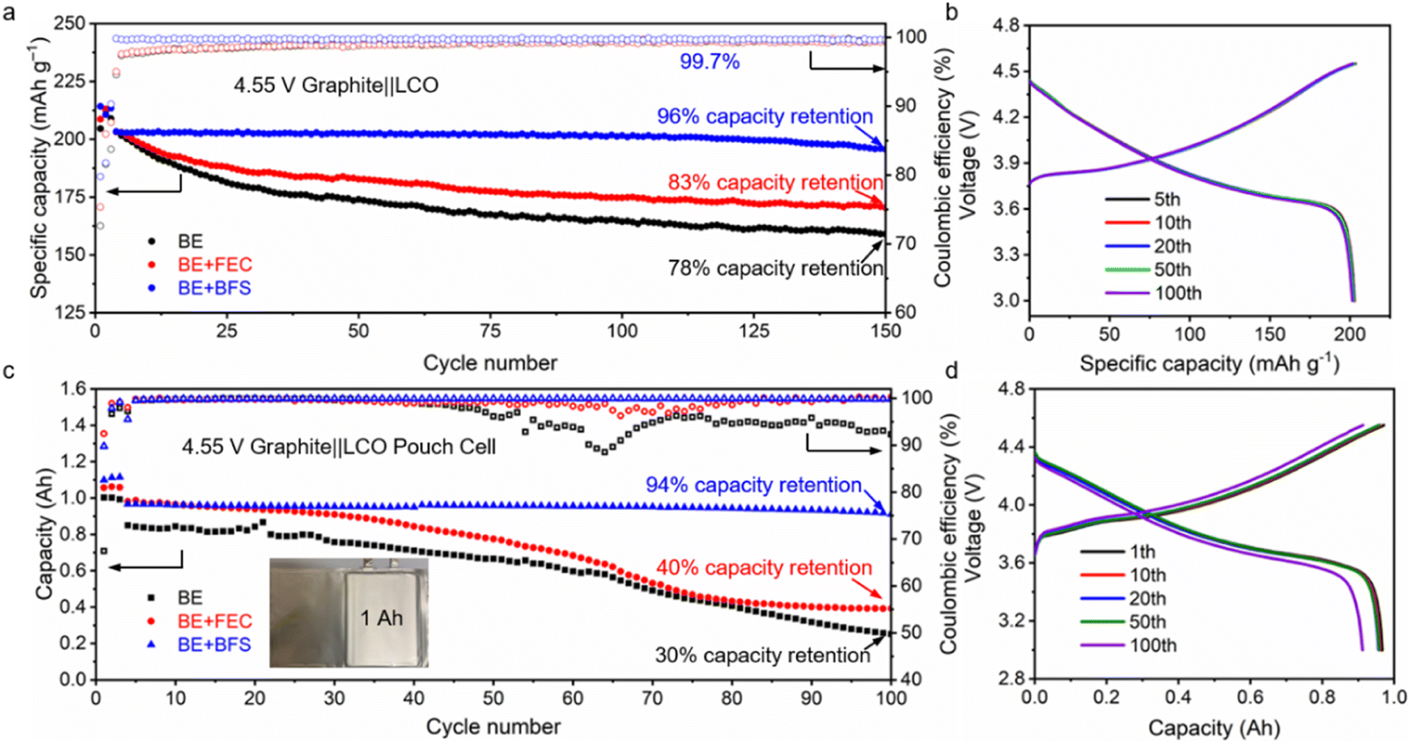 | ||
| Fig. 5 Graphite‖LCO full cell performance. (a) Cycling stability of graphite‖LCO coin cells with different electrolytes after 3 activation cycles at 0.1C between 3 V and 4.55 V. (b) Galvanostatic charge–discharge curves of 4.55 V graphite‖LCO coin cells using the BE + BFS. (c) Cycling stability of 1 Ah-level graphite‖LCO pouch cells with different electrolytes between 3 V and 4.55 V. (d) Galvanostatic charge–discharge curves of 4.55 V graphite‖LCO pouch cells using the BE + BFS. | ||
High temperature reversibility is one of the most important features for the cells but difficult to achieve, since the high temperature drastically accelerates the parasitic reactions between the electrode and electrolytes.58,59 The thicker SEI layer formed at high temperatures results in fast capacity loss. As shown in ESI Fig. 15,† the graphite‖LCO cell cycled with BE retains 80% of its original capacity after only 28 cycles at a high temperature of 60 °C. In contrast, the graphite‖LCO cell using the BE + BFS delivers a stable discharge specific capacity of 166 mA h g−1 after 150 cycles at 60 °C, which corresponds to 83% of its initial capacity. Additionally, the addition of BFS increases the discharge specific capacity of 4.55 V graphite‖LCO cells at a low temperature of 0 °C and −25 °C by 18% and 43%, respectively (ESI Fig. 16†). Therefore, the additive-assisted electrolyte design principle holds promise for practical applications under extreme conditions.
Energy density is a decisive metric for practical applications of LIBs. To maximize the battery energy density, lowering the electrolyte amount and tailoring cathode/anode loading are necessary.60 However, a higher cathode loading usually results in more parasitic side reactions and faster capacity fading. A 1 Ah-level graphite‖LCO pouch cell with a high loading of 2.85 mA h cm−2, a harsh negative-to-positive capacity ratio of ∼1, and a lean electrolyte-to-cathode ratio of 2 g (Ah)−1 makes the evaluation of electrolyte practicality reliable. As shown in Fig. 5c, the 4.55 V graphite‖LCO pouch cells with BE and BE + FEC display rapid deterioration of capacity (30% and 40% retention of its original capacity after 100 cycles, respectively) and greatly increased overpotentials (ESI Fig. 17†). Benefiting from an efficient interfacial passivation film and high ion transport kinetics in the BE + BFS, the graphite‖LCO pouch cell maintains a high CR of 94% over 100 cycles at a charge cut-off voltage of 4.55 V, without obvious polarization (Fig. 5d). Meanwhile, the graphite‖LCO pouch cell with the BE + BFS delivers a high energy density of ∼315 W h kg−1 (ESI Table 4,† calculated from the total weight of the graphite‖LCO pouch cell). The suppressive gas expansion in the pouch cell (ESI Fig. 18†) also demonstrates the improved intrinsic safety of the BE + BFS, making the BE + BFS a promising candidate for the next generation of high-voltage LIBs electrolytes.
Conclusions
In summary, a highly protective SOx-rich interphase with a SO42−/S2O32− redox couple was constructed via additive-assisted electrolyte engineering, which effectively improves the electrochemical performance of graphite‖LCO batteries at high voltages. The additive BFS tends to adsorb on the LCO cathode and helps form a reversible redox couple during the charging/discharging process, which contributes to alleviating oxygen release by reversible reduction/oxidation over cycling, thus successfully inhibiting the decomposition of the electrolyte on the catalytic cathode surface. Meanwhile, the formed highly conductive interphase further improves the cycle life of graphite‖LCO batteries at high voltages. As a proof-of-concept application, the BE + BFS endows a 4.6 V Li‖LCO cell and 4.55 V graphite‖LCO cell with high CRs of 88% over 300 cycles and 96% over 150 cycles, respectively. In addition, a realistic 1 Ah-level 4.55 V graphite‖LCO pouch cell under lean electrolyte conditions (2 g (Ah)−1) also achieves a high CR of 94% after 100 cycles. The reversible redox couple concept in this work opens a new frontier in designing electrolyte for practical high-voltage LIBs.Author contributions
J. Z. and X. F. conceived the idea and designed the experiments. J. Z., S. Z., F. W. and L. C. conducted the electrochemical experiments. J. Z., X. X. and S. G. performed the XPS and ICP-MS analyses. H. Z. and R. L. conducted the calculations. C. L., L. L. and D. L. conducted the TEM analysis. J. Z. wrote the draft manuscript. J. Z., T. D. and X. F. revised the manuscript. X. F. supervised the project. All the authors contributed to the interpretation of the results.Conflicts of interest
There are no conflicts of interest to declare.Acknowledgements
This work was supported by the National Natural Science Foundation of China (22072134, 22161142017, and U21A2081), the Natural Science Foundation of Zhejiang Province (LR23B030002 and LZ21B030002), the Fundamental Research Funds for the Central Universities (2021FZZX001-09), and the “Hundred Talents Program” of Zhejiang University.References
- J. B. Goodenough and Y. Kim, Challenges for rechargeable Li batteries, Chem. Mater., 2009, 22, 587–603 CrossRef.
- J. M. Tarascon and M. Armand, Issues and challenges facing rechargeable lithium batteries, Nature, 2001, 414, 359–367 CrossRef CAS PubMed.
- X. Fan and C. Wang, High-voltage liquid electrolytes for Li batteries: progress and perspectives, Chem. Soc. Rev., 2021, 50, 10486–10566 RSC.
- K. Xu and C. Wang, Batteries: Widening voltage windows, Nat. Energy, 2016, 1, 1–2 Search PubMed.
- M. S. Whittingham, Lithium batteries and cathode materials, Chem. Rev., 2004, 104, 4271–4302 CrossRef CAS PubMed.
- L. Wang, et al., Reviving lithium cobalt oxide-based lithium secondary batteries-toward a higher energy density, Chem. Soc. Rev., 2018, 47, 6505–6602 RSC.
- Y. Lyu, et al., An overview on the advances of LiCoO2 cathodes for lithium-ion batteries, Adv. Energy Mater., 2020, 11, 2000982 CrossRef.
- Q. Liu, et al., Approaching the capacity limit of lithium cobalt oxide in lithium ion batteries via lanthanum and aluminium doping, Nat. Energy, 2018, 3, 936–943 CrossRef CAS.
- J. Chen, et al., Structure/interface coupling effect for high-voltage LiCoO2 cathodes, Adv. Mater., 2022, 34, e2204845 CrossRef PubMed.
- Y. Huang, et al., Mg-pillared LiCoO2: Towards stable cycling at 4.6 V, Angew. Chem., Int. Ed., 2021, 60, 4682–4688 CrossRef CAS PubMed.
- J. Qian, et al., Electrochemical surface passivation of LiCoO2 particles at ultrahigh voltage and its applications in lithium-based batteries, Nat. Commun., 2018, 9, 4918 CrossRef PubMed.
- J. Wan, et al., Revealing the correlation between structure evolution and electrochemical performance of high-voltage lithium cobalt oxide, J. Energy Chem., 2021, 54, 786–794 CrossRef CAS.
- W. Xue, et al., Stabilizing electrode–electrolyte interfaces to realize high-voltage Li‖LiCoO2 batteries by a sulfonamide-based electrolyte, Energy Environ. Sci., 2021, 14, 6030–6040 RSC.
- J. Zhang, et al., Interfacial design for a 4.6 V high-voltage single-crystalline LiCoO2 cathode, Adv. Mater., 2022, 34, e2108353 CrossRef PubMed.
- L. Wang, et al., A novel bifunctional self-stabilized strategy enabling 4.6 V LiCoO2 with excellent long-term cyclability and high-rate capability, Adv. Sci., 2019, 6, 1900355 CrossRef PubMed.
- M. Yoon, et al., Unveiling Nickel chemistry in stabilizing high-voltage cobalt-rich cathodes for lithium-ion batteries, Adv. Funct. Mater., 2019, 30, 1907903 CrossRef.
- P. Yan, et al., Injection of oxygen vacancies in the bulk lattice of layered cathodes, Nat. Nanotechnol., 2019, 14, 602–608 CrossRef CAS PubMed.
- E. Lee and K. A. Persson, Structural and chemical evolution of the layered Li-excess LixMnO3 as a function of Li content from first-principles calculations, Adv. Energy Mater., 2014, 4, 1400498 CrossRef.
- J. Lee, et al., Mitigating oxygen loss to improve the cycling performance of high capacity cation-disordered cathode materials, Nat. Commun., 2017, 8, 981 CrossRef PubMed.
- H. Chen and M. S. Islam, Lithium extraction mechanism in Li-rich Li2MnO3 involving oxygen hole formation and dimerization, Chem. Mater., 2016, 28, 6656–6663 CrossRef CAS.
- C. Sun, et al., High-voltage cycling induced thermal vulnerability in LiCoO2 cathode: cation loss and oxygen release driven by oxygen vacancy migration, ACS Nano, 2020, 14, 6181–6190 CrossRef CAS PubMed.
- A. Yano, et al., LiCoO2 degradation behavior in the high-voltage phase transition region and improved reversibility with surface coating, J. Electrochem. Soc., 2016, 164, A6116–A6122 CrossRef.
- J. Li, et al., Structural origin of the high-voltage instability of lithium cobalt oxide, Nat. Nanotechnol., 2021, 16, 599–605 CrossRef CAS PubMed.
- W. Kong, et al., Tailoring Co3d and O2p band centers to inhibit oxygen escape for stable 4.6 V LiCoO2 Cathodes, Angew. Chem., Int. Ed., 2021, 60, 27102–27112 CrossRef CAS PubMed.
- S. Kalluri, et al., Feasibility of cathode surface coating technology for high-energy lithium-ion and beyond-lithium-ion batteries, Adv. Mater., 2017, 29, 1605807 CrossRef PubMed.
- Y. S. Jung, et al., Unexpected improved performance of ALD coated LiCoO2/graphite Li-ion batteries, Adv. Energy Mater., 2013, 3, 213–219 CrossRef CAS.
- S. Kalluri, et al., Surface engineering strategies of layered LiCoO2 cathode material to realize high-energy and high-voltage Li-Ion cells, Adv. Energy Mater., 2017, 7, 1601507 CrossRef.
- J.-N. Zhang, et al., Trace doping of multiple elements enables stable battery cycling of LiCoO2 at 4.6 V, Nat. Energy, 2019, 4, 594–603 CrossRef CAS.
- N. Qin, et al., Hierarchical doping engineering with active/inert dual elements stabilizes LiCoO2 to 4.6 V, Adv. Energy Mater., 2022, 12, 2201549 CrossRef CAS.
- J. Zhang, et al., Diluent decomposition-assisted formation of LiF-rich solid–electrolyte interfaces enables high-energy Li-metal batteries, J. Energy Chem., 2023, 78, 71–79 CrossRef CAS.
- Y. Huang, et al., Eco-friendly electrolytes via a robust bond design for high-energy Li metal batteries, Energy Environ. Sci., 2022, 15, 4349–4361 RSC.
- X. Ren, et al., Designing advanced in situ electrode/electrolyte interphases for wide temperature operation of 4.5 V Li‖LiCoO2 batteries, Adv. Mater., 2020, 32, e2004898 CrossRef PubMed.
- X. Zheng, et al., Di(methylsulfonyl) ethane: new electrolyte additive for enhancing LiCoO2/electrolyte interface stability under high voltage, ACS Appl. Mater. Interfaces, 2019, 11, 36244–36251 CrossRef CAS PubMed.
- S. S. Zhang, A review on electrolyte additives for lithium-ion batteries, J. Power Sources, 2006, 162, 1379–1394 CrossRef CAS.
- S. Tan, et al., Additive engineering for robust interphases to stabilize high-Ni layered structures at ultra-high voltage of 4.8 V, Nat. Energy, 2022, 7, 484–494 CrossRef CAS.
- A. Fu, et al., Synergistical stabilization of Li metal anodes and LiCoO2 cathodes in high-voltage Li||LiCoO2 batteries by potassium selenocyanate (KSeCN) additive, ACS Energy Lett., 2022, 7, 1364–1373 CrossRef CAS.
- X. Yang, et al., Enabling stable high-voltage LiCoO2 operation by using synergetic interfacial modification strategy, Adv. Funct. Mater., 2020, 30, 2004664 CrossRef CAS.
- Y. Zou, et al., Stabilizing the LiCoO2 interface at high voltage with an electrolyte additive 2, 4, 6-tris (4-fluorophenyl) boroxin, ACS Sustainable Chem. Eng., 2021, 9, 15042–15052 CrossRef CAS.
- Z. Sun, et al., Design of a novel electrolyte additive for high voltage LiCoO2 cathode lithium-ion batteries: lithium 4-benzonitrile trimethyl borate, J. Power Sources, 2021, 503, 230033 CrossRef CAS.
- L. Zhang, et al., 1-(p-toluenesulfonyl) imidazole (PTSI) as the novel bifunctional electrolyte for LiCoO2-based cells with improved performance at high voltage, J. Power Sources, 2021, 491, 229596 CrossRef CAS.
- W. Xue, et al., FSI-inspired solvent and “full fluorosulfonyl” electrolyte for 4 V class lithium-metal batteries, Energy Environ. Sci., 2020, 13, 212–220 RSC.
- Q. Liu, et al., Kinetically determined phase transition from stage II (LiC12) to stage I (LiC6) in a graphite anode for Li-ion batteries, J. Phys. Chem. Lett., 2018, 9, 5567–5573 CrossRef CAS PubMed.
- X. Fan, et al., Highly fluorinated interphases enable high-voltage Li-metal batteries, Chem, 2018, 4, 174–185 CAS.
- S. Jiao, et al., Stable cycling of high-voltage lithium metal batteries in ether electrolytes, Nat. Energy, 2018, 3, 739–746 CrossRef CAS.
- J. Zheng, et al., Electrolyte additive enabled fast charging and stable cycling lithium metal batteries, Nat. Energy, 2017, 2, 17012 CrossRef CAS.
- X. Fan, et al., Non-flammable electrolyte enables Li-metal batteries with aggressive cathode chemistries, Nat. Nanotechnol., 2018, 13, 715–722 CrossRef CAS PubMed.
- X.-Q. Zhang, et al., Fluoroethylene carbonate additives to render uniform Li deposits in lithium metal batteries, Adv. Funct. Mater., 2017, 27, 1605989 CrossRef.
- E. Markevich, et al., Fluoroethylene carbonate as an important component in electrolyte solutions for high-voltage lithium batteries: role of surface chemistry on the cathode, Langmuir, 2014, 30, 7414–7424 CrossRef CAS PubMed.
- X. Xu, et al., A room-temperature sodium-sulfur battery with high capacity and stable cycling performance, Nat. Commun., 2018, 9, 3870 CrossRef PubMed.
- H. Sun, et al., A high-performance potassium metal battery using safe ionic liquid electrolyte, Proc. Natl. Acad. Sci., 2020, 117, 27847–27853 CrossRef CAS PubMed.
- S. Hu, et al., Insight of a phase compatible surface coating for long-durable Li-rich layered oxide cathode, Adv. Energy Mater., 2019, 9, 1901795 CrossRef.
- N. P. W. Pieczonka, et al., Understanding transition-metal dissolution behavior in LiNi0.5Mn1.5O4 high-voltage spinel for lithium ion batteries, J. Phys. Chem. C, 2013, 117, 15947–15957 CrossRef CAS.
- J. A. Gilbert, I. A. Shkrob and D. P. Abraham, Transition metal dissolution, ion migration, electrocatalytic reduction and capacity loss in lithium-ion full cells, J. Electrochem. Soc., 2017, 164, A389–A399 CrossRef CAS.
- G. G. Amatucci, J. M. Tarascon and L. C. Klein, CoO2, the end member of the LixCoO2 solid solution, J. Electrochem. Soc., 1996, 143, 1114 CrossRef CAS.
- V. Knap, et al., Investigation of the self-discharge behavior of lithium-sulfur batteries, J. Electrochem. Soc., 2016, 163, A911–A916 CrossRef CAS.
- J. Liu, et al., Pathways for practical high-energy long-cycling lithium metal batteries, Nat. Energy, 2019, 4, 180–186 CrossRef CAS.
- G. M. Hobold, et al., Moving beyond 99.9% Coulombic efficiency for lithium anodes in liquid electrolytes, Nat. Energy, 2021, 6, 951–960 CrossRef CAS.
- J. Hou, et al., Fundamentals and challenges of lithium ion batteries at temperatures between −40 and 60 °C, Adv. Energy Mater., 2020, 10, 1904152 CrossRef CAS.
- M.-T. F. Rodrigues, et al., A materials perspective on Li-ion batteries at extreme temperatures, Nat. Energy, 2017, 2, 1–14 Search PubMed.
- Z. Wu, et al., Deciphering and modulating energetics of solvation structure enables aggressive high-voltage chemistry of Li metal batteries, Chem, 2023, 9, 650–664 CAS.
Footnote |
| † Electronic supplementary information (ESI) available. See DOI: https://doi.org/10.1039/d2ta09893h |
| This journal is © The Royal Society of Chemistry 2023 |