
 Open Access Article
 This Open Access Article is licensed under a
 Creative Commons Attribution 3.0 Unported Licence
Reclamation and reuse of graphite from electric vehicle lithium-ion battery anodes via water delamination†
Alexander T.
Sargent
 *ab,
Zoë
Henderson
c,
Alex S.
Walton
c,
Ben F.
Spencer
d,
Luke
Sweeney
ab,
Wendy R.
Flavell
e,
Paul A.
Anderson
ab,
Emma
Kendrick
bf,
Peter R.
Slater
*ab and
Phoebe K.
Allan
*ab
*ab,
Zoë
Henderson
c,
Alex S.
Walton
c,
Ben F.
Spencer
d,
Luke
Sweeney
ab,
Wendy R.
Flavell
e,
Paul A.
Anderson
ab,
Emma
Kendrick
bf,
Peter R.
Slater
*ab and
Phoebe K.
Allan
*ab
aSchool of Chemistry, University of Birmingham, Birmingham, B15 2TT, UK. E-mail: axs1256@student.bham.ac.uk; p.r.slater@bham.ac.uk; p.allan@bham.ac.uk
bThe Faraday Institution, Quad One, Harwell Science and Innovation Campus, Didcot, OX11 0RA, UK
cDepartment of Chemistry, Photon Science Institute, University of Manchester, Oxford Road, Manchester, M13 9PL, UK
dDepartment of Materials, Henry Royce Institute, University of Manchester, Oxford Road, Manchester, M13 9PL, UK
eDepartment of Physics and Astronomy, Henry Royce Institute, Photon Science Institute, University of Manchester, Oxford Road, Manchester, M13 9PL, UK
fSchool of Metallurgy and Materials, University of Birmingham, Birmingham, B15 2TT, UK
First published on 20th March 2023
Abstract
Early electric vehicle anodes utilised poly(vinylidene difluoride) (PVDF) as the binder. Due to its lack of solubility in non-harmful solvents, PVDF potentially leads to challenges with anode recycling. In this work we use anodes from discharged and disassembled first-generation end-of-life (EoL) and first-generation quality-control-rejected (QCR) Nissan Leaf cells to demonstrate that PVDF-bound anode active material can be separated from the copper current collector effectively via simple submersion in water. X-ray photoelectron spectroscopy (XPS) and inductively coupled plasma (ICP) spectroscopy were used to confirm the presence of lithiated graphite, suggesting that the delamination process is driven by the reaction of remnant lithiated graphite with water forming H2 which creates localised areas of heat and pressure. The effectiveness of anode delamination via water diminished with the time exposed to air due to the contact with moisture/air slowly hydrolysing and oxidising this lithiated graphite. Electrochemical measurements confirm that annealing the recovered graphite material at 500 °C for 1 h in air to remove solid electrolyte interface layer and PVDF contamination can regenerate material with a performance comparable to commercial graphite. These results suggest that optimised reclamation and regeneration procedures for EoL anodes can provide a source for high performing electrochemical graphite, helping to secure future supplies of this critical raw material and alleviating concerns over future accumulation of battery waste.
Introduction
Lithium-ion batteries (LIBs) are an important stepping stone towards a decarbonised future. It is predicted that electric vehicles (EVs) could dominate the automotive market by 2040 with 95% of cars purchased being electric. This leads to a forecast scenario that the production of EVs could increase to 1.6 million units per year by 2040 in the UK alone.1–3 In conjunction with the decarbonisation of the energy grid, this could potentially allow the UK to achieve carbon neutrality by 2050. Other countries worldwide are adopting a similar approach of transitioning towards EVs, leading to a predicted exponential growth in battery production for EVs. It takes approximately 10 years for the battery in an EV to reach end-of-life (EoL) meaning that the 5.1 million stock of global EVs in 2018 alone will soon need to be recycled.1,4,5 This also excludes LIB production scrap, recalls, factory rejects and batteries from hand held devices that already saturate the LIB recycling market today.Recycling of LIBs is important not only because the vast volume of potential waste creates dangers of spontaneous fires and toxic leakage, but also because some of the materials used to make LIBs are unsustainable, or have poor geopolitical security.6–9 Moreover, EV manufacturing has a high CO2 cost, currently around 60% greater than for the construction of an internal combustion vehicle;10 efficient recycling and reuse routes are critical to reducing this impact.
Current commercial industrial-scale recycling of LIBs is sparse in many parts of the world, and existing facilities generally focus on the metals of high economic value, such as cobalt, nickel and copper; for instance Umicore's pyrometallurgical plants.11 This being said, there have been many small-scale advances, developing physical, pyrometallurgical and hydrometallurgical techniques that focus on extracting all parts of the battery.11–14 However, a large bias towards the cathode remains, with the anode, comprised primarily of graphite, either being sold as scrap, pyrolyzed, or used as a reducing agent in pyrometallurgical recycling processes.12,15–17
Current commercial EV LIBs can contain around 11 times more graphite than lithium by mass.18,19 In 2021 this resulted in a consumption of 437![[thin space (1/6-em)]](https://www.rsc.org/images/entities/char_2009.gif) 000 tonnes of graphite by the EV battery sector.20
000 tonnes of graphite by the EV battery sector.20
This ‘battery grade’ graphite originates as either large-flaked natural graphite (this appears on the EU Critical Raw Materials List for 2020) or highly-pure synthetic graphite.21 Once obtained, the graphite must be sphericalised, which uses jet-milling to agglomerate the particles. A secondary carbon coating is then applied to reduce first cycle loss in cells.22 The low-yield, high-energy process of sphericalisation leads to a worryingly large environmental impact.18,22,23 The extraction of natural graphite (itself a critical material) does not fare much better, requiring large quantities of hazardous solvents and acids (hydrochloric acid, chlorine gas and sodium fluoride) for both mining and purification. In 2018 the Argonne National Laboratory Greenhouse Gases, Regulated Emissions, and Energy Use in Transportation project reported large global warming potentials for both synthetic and natural graphite.23 Previous work on extracting graphite from the anode has focused on routes to up-cycled materials, for instance converting the spent graphite into graphene, active carbons or carbon aerogels.23–25 This leaves the reuse of extracted graphite as an anode material relatively unexplored.
Despite the importance of circular economies for LiBs, careful selection of recycling routes must be made to attain beneficial environmental and economic impacts. Processes that use large quantities of inorganic acids or complex steps including high-temperature calcination can themselves have large negative impacts. An example of this is shown by the work of Rey et al.,23 where comparisons of the global warming potentials of two graphite recycling techniques, ‘Fenton and floatation’ compared to ‘pyrolysis and flotation’, showed drastically different values (48.4 kgCO2 equiv. kggraphite−1 and 0.53 kgCO2 equiv. kggraphite−1, respectively).
A major challenge for extracting graphite from the anode for treatment and reuse is delaminating the film containing the graphite (as well as the binder, conductive carbon and additives) from the copper current collector. In first-generation EV batteries (like those used within a Nissan Leaf constructed between 2010–2017), poly(vinylidene difluoride) (PVDF) is used as the binder.26,27 The difficulty lies in finding a safe solvent to dissolve PVDF, unlike binders used in current generation EV anodes that can dissolve in water, thus the delamination and therefore recycling of first-generation anode films is difficult, particularly to achieve this in a scalable manner with minimum energetic cost and environmental impact. Currently N-methyl-2-pyrrolidone (NMP) is most commonly used for delamination, however other solvents such as dimethyl sulfoxide (DMSO) and dimethyl isosorbide (DMI) have been proposed as less toxic candidates.28 However, the inherent danger of using these alternative solvents lies in their high dermal absorption, providing a route of entry into the body for PVDF and any toxic compounds which may be dissolved within the solution.
Within industry recycling processes, delamination is often omitted, with shredding being the preferred option due to the processes scalability and simplicity, however the use of shredding can cause major cross contamination which further complicates separation processes.
Mechanical delamination, aimed to be industrially scalable, focusing on sonication,4,29 has been reported, showing promising electrode delamination. Acoustic pressure created by a sonotrode in an aqueous environment creates vapour-filled cavities to form and randomly implode. The implosions near the surface of the electrode release a large amount of energy in the form of high local pressure which is able to breakdown the binder and release the film from the current collector.4,16,24,30
Here, we show an alternative approach to graphite extraction, by submerging first-generation (PVDF-bound) anodes into water causing delamination without the need for ultrasonication. Trace amounts of lithiated graphite within the anode react with water to form local areas of heat and varying pressure, causing the electrode to delaminate. Unlike other research, often carried out on fully discharged and/or air-exposed electrodes, water delamination has been previously reported however since then, little research has gone into further understanding water-based delamination methods.31
After a low temperature (500 °C for 1 h in air) heat treatment we show that the obtained graphite shows excellent electrochemical performance. We demonstrate the efficacy of this technique in a range of materials representative of near future recycling streams (including from heavily used EV cells), including quality-control-reject (QCR) material and EoL materials from a used EV at various states-of-health. We also explore the effect of air exposure duration, age and cell OCV on the delamination process and on the resultant solution's lithium concentration.
Method
Anode materials
Anodes were taken from pouch cells from a first-generation Nissan Leaf; either quality-control-rejected cells or cells from a used car. Cells were used either as sourced or subsequently aged to different states-of-health. Anodes consisted of 12 μm thick copper foil sandwiched between two layers of 70 μm of anode film. The anode films (AF) contained graphite, carbon black, PVDF and unknown additives. More information on the origin of these anodes can be found in Table 1. The colour scheme and sample IDs within Table 1 will be used to refer to each anode. AF and graphite obtained after delamination and annealing are also given the same colour scheme and sample IDs. Pouch cells were opened within an argon glovebox (<0.1 ppm H2O and O2) using a ceramic scalpel to cut around the sides of the casing, the electrodes and separators could then be pulled out, separated and left to dry. Full details on a similar dismantling procedure are given by Marshall et al.32 Before exposure to atmospheric conditions, anodes were washed with dimethylcarbonate (DMC) (Sigma-Aldrich, Anhydrous, ≥99%) and dried to remove any remaining lithium hexafluorophosphate (LiPF6) salt that could react with water to produce hydrogen fluoride.| Sample ID | Sample history | OCVa | |
|---|---|---|---|
| a Open cell voltage of the cell before dismantlement. b State of charge. | |||

|
QCR | Quality control reject pouch cell for a first-generation Nissan leaf. The cell had appeared to have gone through formation cycles. This cell was discharged below 0% SOCb to an OCV of 0 V by Nissan. The cell was left to rest, causing the OCV to rise | <1 V |

|
QCR II | Quality control reject pouch cell for a first-generation Nissan leaf. The cell had appeared to have gone through formation cycles. Electronically discharged to a SOC of 0% | 3.00 V |

|
EoL | A first-generation battery module taken from a used Nissan leaf with an odometer reading of ∼40000 miles. Electronically discharged to a SOC of 0% |
3.75 V |

|
EoL II | Same origin as EoL however, was further cycled under a ‘mild overcharging regime’ by P. S. Attidekou et al.89 | 3.22 V |
| The cell was run for 500 cycles where only 87.12% of its original capacity remained. Electronically discharged to a SOC of 0% | |||

|
EoL III | First-generation EoL Nissan leaf pouch cell cycled by P. S. Attidekou et al.89 to induce ‘severe degradation related to overcharging | 3.27 V |
| After 250 cycles a knee point was reached and cycling stopped after 300 cycles with only ∼30% of its original capacity. Electronically discharged to a SOC of 0% | |||
Delamination
Portions of anodes were removed from an inert argon atmosphere and left for either 1 hour, 24 hours, 2 weeks or 4 weeks in air before submersion into a stirred beaker of deionised (DI) water. Typically around 2 g of anode was submerged in 80 ml of DI water, however, in a later experiment a single sheet of EoL (around 13.5 g) was also delaminated using 450 ml of DI water. Once delaminated, the copper and AF were separated and washed with more DI water before drying. If no delamination occurred after 2 h of water submersion it was reported to be unsuccessful. For inductively coupled plasma-optical emission spectrometry (ICP-OES) analysis, a 10 mm disk of each anode weighing around ∼0.02 g was used. This disk was submerged for 1 hour in 20 ml of DI water before filtered aliquots were extracted.Annealing and coin cell manufacture
AF were heated in a furnace (within a fume cupboard) in air to 500 °C for 1 hour at a ramp rate of 10 °C min−1, to remove PVDF and solid electrolyte interface (SEI) contamination from the graphite, and left to cool naturally.In order to analyse the electrochemical performance, a slurry was made using the recovered graphite with powdered sodium carboxymethyl cellulose (Na CMC) (Sigma-Aldrich, 250000 Mw, 0.7 degree of substitution), Super P® conductive carbon black (CB) (Sigma-Aldrich, ≥99%) and styrene-butadiene rubber (SBR) (Sigma-Aldrich, 50 wt%). The slurry was made with a 30–20 wt% with water and a weight ratio of 90:2:5:3 of graphite:CB:Na CMC:SBR respectively. This slurry was coated onto copper foil (MTI corporation, 9 μm) using a doctor blade, then dried on a hot plate at 40 °C before being transferred to a vacuum oven (set to 100 °C) for 24 h. The dried coatings were then calandered and dried under vacuum for another 24 h. Electrode information for each AF is given in Table 2. MAGE3 graphite (Hitachi Chemical, Sakuragawa, Japan) was used as a standard for comparison.
| Graphite used | Active mass loading (mg cm−2) | Coating thickness (μm) | Coating porosity (%) |
|---|---|---|---|
| QCR II 1 h | 4.33 ± 0.09 | 30.7 ± 0.6 | 23.6 ± 0.6 |
| QCR II 2 weeks | 4.28 ± 0.9 | 30.3 ± 2.1 | 22.0 ± 1.6 |
| EoL 1 h | 5.4 ± 0.1 | 33.3 ± 0.6 | 15.9 ± 0.4 |
| EoL 2 weeks | 4.30 ± 0.06 | 45.7 ± 0.6 | 34.8 + 1.5 |
| EoL II 1 h | 6.0 ± 0.5 | 47.0 ± 2.6 | 31.7 ± 2.8 |
| EoL II 2 weeks | 6.3 ± 0.2 | 55.0 ± 3.5 | 36.1 ± 2.4 |
| EoL III 1 h | 4.2 ± 0.5 | 47.0 ± 2.6 | 49.9 ± 5.3 |
| EoL III 2 weeks | 3.1 ± 0.1 | 36.3 ± 2.1 | 54.4 ± 3.5 |
| MAGE3 | 5.74 ± 0.04 | 57.3 ± 6.4 | 46.4 ± 5.2 |
CR2032 coin cells were made by first punching a 12 mm disk of electrode material and transferring this into an inert atmosphere. Glass microfiber (Whatman, 1.2 μm thick, 55 mm diameter) was used as the separator, 100 μl of 1 M lithium hexafluorophosphate (LiPF6) in ethylene carbonate (EC) and DMC (EC:DMC 50:50 (v/v)) (Sigma-Aldrich) was used as the electrolyte. Lithium metal (PI-KEM, 15.6 mm × 0.25 mm thick) that was scraped and punched to a diameter of 1.27 cm was used as the counter electrode. Before battery testing the coin cells were rested for between 6–24 h to equilibrate.
Characterisation
Prior to washing with DMC, 1.27 cm disks taken from the centre of each anode were transferred via a vacuum vessel from an Ar glovebox (<0.1 ppm H2O and O2) for X-ray Photoelectron Spectroscopy (XPS) and Hard X-ray Photoelectron Spectroscopy (HAXPES) analysis.HAXPES was performed using monochromated Ga Kα X-ray radiation (9250 eV, 3.57 mA emission at 250 W, micro-focussed to 50 μm) and an EW-4000 high voltage electron energy analyser (HAXPES-Lab, Scienta Omicron GmbH); the instrument has a base vacuum pressure of ∼5 × 10⁻¹⁰ mbar.33,34 The entrance slit width used was 0.8 mm, and the pass energies used for survey and core level spectra were 500 and 200 eV, respectively, with total energy resolutions of 2.0 and 0.6 eV, respectively.33 The HAXPES instrument also has a monochromated Al Kα X-ray source (1486 eV, 20 mA emission at 300 W) for surface sensitive XPS at the same sample position. Charge neutralisation for insulating samples is achieved using a low energy electron flood source as required (FS40A, PreVac). Binding energy scale calibration was performed using C–C in the C 1s photoelectron peak at 284.8 eV. Analysis and curve fitting were performed using Lorentzian-approximation peaks (LA(1.53, 243)) for all peaks except for lithiated graphite where an asymmetric Lorentzian-approximation (LF(0.65, 1.17, 550, 180, 2)) was fitted. All fittings were performed using Casa XPS.35 Peak binding energies and widths were constrained according to environments found in literature; these are given in Table S1 within the ESI.† Core-level relative sensitivity factors for HAXPES quantification were calculated according to Cant et al.36 Standard deviations were calculated in casaXPS using a Monte Carlo method to assess the influence of noise on the background and in turn on the fitted peak area.37
A Philips XL30 FEG scanning electron microscope (SEM) was used to gain high resolution images of the surface of the anodes and recovered graphite. An accelerating voltage of 5 kV was used with a secondary electron detector.
ICP-OES (5110, Agilent) was used to determine the chemical composition of the resultant solution after submersion of anodes in DI water for 1 h. 20 μl of ultrapure HNO3 (67–69%, VWR chemicals) was added to removed aliquots to prevent precipitation of metals and dilutions used 2% ultrapure HNO3. Standards were prepared using a multi-element standard (10 μg ml−1, 5% HNO3 matrix, TruQms).
Raman spectroscopy measurements were taken from ten points on the surface of each sample before and after water submersion. These spectra were collected after certain periods of air exposure (1 h, 24 h, 2 weeks and 4 weeks). Twenty randomly positioned point scans on the 1 hour and 2 week annealed samples were also taken.
For the Raman measurements, a Renishaw inVia Raman microscope with a green laser (wavelength of 532 nm) at 100% laser power was used. For each spot measured, 5 acquisitions were taken. MATLAB was used to fit simultaneously all Raman spectra, giving positions, intensities and integrated intensities for each peak. The program used modified functions created by O'Haver and D'Errico to create a boundary constrained scalar minimising function to fit the graphitic Raman peaks.38,39 Fits of the D4, D, D3, G and D′ peaks were made by first applying a linear background fit then fitting Voigt-shaped peaks for the D bands and Lorentzian-shaped peaks for the G and D′ bands. Peak position limits of 1150–1310 cm−1 (D4), 1320–1380 cm−1 (D), 1350–1450 cm−1 (D3), 1525–1590 cm−1 (G) and 1590–1635 cm−1 (D′) were used. Fig. S1† shows examples of the fits achieved for samples of EoL material. ID/IG ratios were calculated using the sum of all D bands' (excluding D′) integrated intensities divided by the integrated intensity of the G band. Distributions of ID/IG ratios could then be created from the multiple scans on each sample.
For short-term cycling, assuming a theoretical capacity of 372 mA h g−1, the first five cycles of battery testing were run at a current rate (C rate) of C/20 (18.6 mA g−1) for both charge and discharge processes; this was then switched to C/5 (74.4 mA g−1) for the following 15 cycles. MAGE3, EoL III 1 h and EoL III 2 weeks were also ran for 200 asymmetric cycles after two formation cycles at C/20. Cells were charged at C/2 (186 mA g−1) and discharged at 1C (372 mA g−1). A voltage range of 0.005 V to 1.5 V vs. Li+/Li was used and all galvanostatic testing was performed using a Bio-logic SP50 cell tester on a BCS-805 module. All cell data presented are an average of three cells.
Results and discussion
XPS and HAXPES anode surface study
In order to gather initial information on the nature of the anode surface, an ex situ study of each anode before DMC wash and air exposure was conducted using XPS and HAXPES analysis. A combination of the two techniques was used to compare the top surface interface (probed with XPS) to the buried surface (observed with HAXPES). Percentage compositions of each environment for the C 1s and F 1s regions are given in Table 3, atomic percentages of Li, C, O, F, P, S, Mn, Ni and Cu are given in Table 4. Fig. 1 displays normalised C 1s, F 1s and Mn 2p spectra with fitted peaks for each anode.| Carbon 1s (% composition) | Fluorine 1s (% composition) | ||||||||||
|---|---|---|---|---|---|---|---|---|---|---|---|
| LiG | C–C/C–H | C–O | C![[double bond, length as m-dash]](https://www.rsc.org/images/entities/char_e001.gif) O O |
O–CO |
CO32− | Fluorocarbon | LiPF6 | LiyPFx/LiPFx(OR)y | LiF | ||
| QCR | XPS | 1.1 ± 0.9 | 53.3 ± 2.0 | 19.3 ± 1.4 | 15.7 ± 0.8 | 6.4 ± 0.7 | 4.3 ± 0.7 | — | 10.5 ± 1.0 | 32.8 ± 1.2 | 56.8 ± 1.8 |
| HAXPES | 0 ± 0 | 58.3 ± 5.2 | 18.1 ± 6.7 | 12.2 ± 4.9 | 6.0 ± 2.6 | 5.6 ± 2.1 | — | — | 32.8 ± 1.1 | 67.2 ± 1.4 | |
| QCR II | XPS | 4.4 ± 1.9 | 56.9 ± 2.7 | 16.1 ± 3.9 | 5.5 ± 1.6 | 8.7 ± 1.6 | 8.5 ± 1.2 | — | — | 24.4 ± 1.6 | 75.6 ± 1.8 |
| HAXPES | 31.2 ± 5.4 | 37.5 ± 5.0 | 16.6 ± 3.3 | 0 ± 0 | 5.4 ± 2.6 | 9.4 ± 2.3 | — | — | 32.6 ± 2.1 | 67.4 ± 2.5 | |
| EoL | XPS | 2.6 ± 1.2 | 30.0 ± 1.9 | 20.2 ± 3.5 | 18.3 ± 2.8 | 2.9 ± 1.1 | 26.0 ± 1.9 | — | — | 42.6 ± 1.3 | 57.5 ± 1.4 |
| HAXPES | 27.5 ± 4.8 | 19.8 ± 4.1 | 16.0 ± 2.6 | 10.1 ± 4.4 | 10.0 ± 1.8 | 16.6 ± 2.3 | — | — | 35.4 ± 0.8 | 64.7 ± 0.9 | |
| EoL II | XPS | 4.2 ± 1.2 | 47.4 ± 1.8 | 16.7 ± 2.3 | 17.6 ± 1.8 | 7.5 ± 0.6 | 6.6 ± 0.6 | — | 11.8 ± 2.0 | 52.1 ± 2.1 | 36.2 ± 0.8 |
| HAXPES | 13.3 ± 2.7 | 61.0 ± 4.7 | 5.8 ± 2.3 | 6.8 ± 3.4 | 6.5 ± 1.4 | 6.7 ± 1.5 | — | — | 41.5 ± 1.8 | 58.5 ± 1.9 | |
| EoL III | XPS | 1.7 ± 1.5 | 37.5 ± 3.4 | 15.7 ± 3.7 | 15.7 ± 2.4 | 13.3 ± 1.3 | 9.9 ± 1.2 | 7.2 ± 0.3 | 4.0 ± 1.0 | 23.0 ± 1.3 | 73.0 ± 2.3 |
| HAXPES | 3.2 ± 3.5 | 45.4 ± 5.5 | 15.8 ± 4.5 | 5.9 ± 3.0 | 11.4 ± 2.8 | 18.3 ± 3.3 | — | 5.0 ± 2.2 | 20.1 ± 3.5 | 74.9 ± 7.0 | |
| Lithium (at%) | Carbon (at%) | Oxygen (at%) | Fluorine (at%) | Phosphorus (at%) | Sulphur (at%) | Manganese (at%) | Nickel (at%) | Copper (at%) | ||
|---|---|---|---|---|---|---|---|---|---|---|
| QCR | XPS | 31.7 ± 4.4 | 24.2 ± 0.8 | 13.1 ± 0.3 | 22.4 ± 0.3 | 2.9 ± 0.7 | 2.1 ± 0.6 | 1.00 ± 0.19 | 0.77 ± 0.13 | 1.80 ± 0.31 |
| HAXPES | 13.4 ± 5.4 | 28.0 ± 2.5 | 11.1 ± 1.0 | 40.3 ± 0.6 | 2.4 ± 0.1 | 2.3 ± 0.2 | 0.36 ± 0.03 | 0.79 ± 0.08 | 1.34 ± 0.27 | |
| QCR II | XPS | 39.1 ± 1.6 | 28.7 ± 0.8 | 16.7 ± 0.4 | 12.3 ± 0.3 | 0.8 ± 0.2 | 1.9 ± 0.2 | — | 0.45 ± 0.13 | — |
| HAXPES | 28.2 ± 4.9 | 29.6 ± 1.8 | 25.4 ± 0.8 | 15.5 ± 0.6 | 0.3 ± 0.1 | 1.0 ± 0.1 | — | — | — | |
| EoL | XPS | 40.3 ± 1.2 | 20.5 ± 0.6 | 18.6 ± 0.3 | 16.9 ± 0.2 | 3.1 ± 0.2 | 0.3 ± 0.1 | — | 0.35 ± 0.10 | — |
| HAXPES | 28.0 ± 4.5 | 18.6 ± 1.1 | 16.0 ± 0.4 | 36.2 ± 0.3 | 1.1 ± 0.1 | 0.2 ± 0.1 | — | — | — | |
| EoL II | XPS | 40.7 ± 7.6 | 28.1 ± 1.2 | 15.6 ± 0.4 | 11.5 ± 0.5 | 2.9 ± 0.4 | — | 0.72 ± 0.08 | 0.18 ± 0.30 | — |
| HAXPES | 13.8 ± 3.6 | 49.6 ± 1.6 | 17.5 ± 0.5 | 16.7 ± 0.4 | 1.4 ± 0.1 | 0.3 ± 0.1 | 0.79 ± 0.02 | — | — | |
| EoL III | XPS | 46.2 ± 1.3 | 17.7 ± 0.5 | 13.9 ± 0.2 | 20.7 ± 0.2 | 0.6 ± 0.1 | 0.3 ± 0.1 | 0.12 ± 0.06 | 0.56 ± 0.09 | — |
| HAXPES | 35.8 ± 3.3 | 18.3 ± 1.0 | 26.6 ± 0.4 | 18.5 ± 0.4 | 0.3 ± 0.1 | 0.2 ± 0.1 | 0.22 ± 0.02 | — | — |
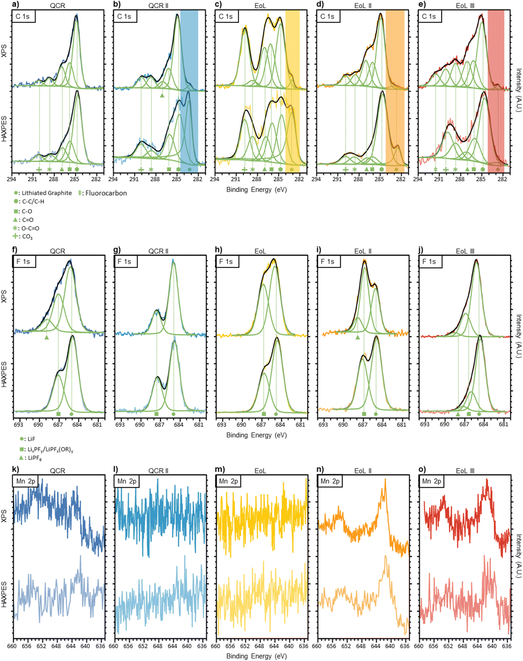 | ||
| Fig. 1 (a–e) Carbon 1s XPS (top row) and HAXPES (bottom row) of anodes before DMC wash and air exposure. Each signal fitting consist of five Voigt peaks with constrained binding energies. The lithiated graphite region is highlighted with a transparent band and was fitted using an asymmetric peak. (f–j) Fluorine 1s XPS (top row) and HAXPES (bottom row) of anodes before DMC wash and air exposure. Two to three peaks were fitted for the calculated signal, representing LiPF6, LixPFy/LiPFx(OR)y and LiF environments. (k–o) Manganese 2p XPS (top row) and HAXPES (bottom row) of anodes before DMC wash and air exposure. No peaks were fitted due to the asymmetry and complex splitting caused by the d-band in transition metals, therefore comparisons to literature were conducted. QCR is shown in dark blue on the left, QCR II in turquoise, EoL in the middle shown in yellow, EoL II in orange and EoL III in red on the right. Peak position and FWHM used for the carbon 1s and fluorine 1s regions are given in Table S2.† | ||
The C 1s spectra for each anode are given in Fig. 1a–e. The peaks at around 284.8 eV are likely to result from aliphatic carbon, however, graphite would also produce an asymmetric peak around this region.40 As XPS is surface-sensitive and some form of solid electrolyte interface (SEI) was expected to be present on all anodes, a symmetrical peak representing aliphatic carbon was fitted with asymmetric character from the graphite ignored. Four peaks were used to simulate the changes in the more oxidised region between 285–292 eV. The four peaks were given the nomenclature: C–O (∼286.1 eV), CO (∼287.1 eV), O–CO (∼288.7 eV) and CO32− (∼290.0 eV) that is typically found in the literature.41–45 These assignments correspond to a variety of molecules that are found in the SEI including (CH2OCO2Li)2, ROCO2Li and polycarbonates that form due to electrolyte reduction.46 However, these assumptions are an over-simplification and do not lead to a perfect fit. The complex history of each anode can lead to a variety of other C 1s environments including CH2-CF2, C-SOx, other electrolyte reduction products and chemical environments originating from additives.41–45 To avoid overfitting this region, the changes in intensity of only these four SEI resultant peaks were studied. An additional peak at 291.6 eV BE was required for the C 1s XPS spectrum of EoL III which may be ascribed to fluorocarbon bonding.47
Comparing both QCR anodes to the three EoL anodes it can be seen that continuous cycling deposits more of these organic species on the surface, illustrated by the general increase in intensity within this oxidised region compared to the aliphatic carbon peak within XPS. Within this oxidised region there are only minor changes when comparing XPS to HAXPES on the same sample, which could suggest that in terms of carbonaceous species, these remain fairly consistent through the bulk and surface of the SEI. One notable peak is that which appears at a binding energy below that of the aliphatic peak at around 283 eV. This peak is typical of metal carbides and for this study has been assigned to lithiated graphite.41 This peak was observed in all spectra apart from that corresponding to the over-discharged QCR anode, for which a minimal amount of lithiated graphite would be expected due to the low OCV. This peak also increases in intensity when the deeper penetrating HAXPES is used, further suggesting that this is due to lithiated graphite rather than some form of metal carbide in the SEI. Trace amounts of lithiated graphite from incomplete delithiation or areas of the anode which are electronically isolated would be expected due to being dismantled with an OCV of ∼3 V.48 Under HAXPES analysis the intensity of the lithiated graphite peak decreases in the order of QCR II > EoL > EoL II > EoL III, perhaps suggesting a corresponding increase in SEI thickness which obscures the graphite surface.
The F 1s region for each anode scanned using soft and hard X-rays are shown in Fig. 1f–j. Three peaks have been assigned to this region representing environments similar to LiF (∼685.1 eV), LixPFy or LiPFx(OR)y (∼686.9 eV) and LiPF6 (∼688.4 eV).49 LiPF6 was only present in QCR, EoL II and EoL III XPS scans as well as the HAXPES study of EoL III. The LiPF6 salt may remain on the surface after the evaporation of volatile electrolyte solvents. LiF, LixPFy and LiPFx(OR)y are thought to result from the reduction of LiPF6.49 A subtle increase in the LixPFy/LiPFx(OR)y peak can be found between QCR II < EoL < EoL II, suggesting that as the battery ages the components making up the SEI surface are more covalent. A similar trend can be found when comparing XPS to HAXPES between all EoL anodes, where the LiF peak increases in intensity for the deeper penetrating HAXPES scan. This is consistent with previous studies suggesting that SEI formation closer to the surface of the electrode has access to desolvated Li+ ions and salt anions leading to the formation of more inorganic species, whereas the SEI surface closer to the electrolyte has access to more solvent molecules, leading to a composition with more organic species.42,50,51
Cycling first-generation cathode materials (a mix of lithium manganese oxide (LMO) spinel and a nickel-rich layered oxide) has the potential for metals to dissolve, migrate and deposit onto the surface of the anode.52 The contamination of manganese and nickel on the anodes was observed in this study and is shown in Table 4. However, concentrations of cobalt were below the limit of detection. As dissolution occurs stoichiometrically and the cathodes within the studied cells contain a lower cobalt content compared to the other metals, this was expected.52 Manganese deposition is a common aging mechanism discussed in literature;52–55Fig. 1k to o and Table 4 show that Manganese deposition affect the more aged samples EoL II and EoL III and not QCR II and EoL. This results from some disproportionation of Mn(III) at the cathode interface with the electrolyte during cycling, subsequently leading to Mn(II) dissolving into the electrolyte which can then migrate to the anode.53 The peak shape implies that manganese on the surface of the anodes remains in an oxidised state, likely to be +2.54,56,57 As this was an ex situ study it is unknown whether manganese deposits first as a metal, later to be re-oxidised by the electrolyte to +2, or deposits into the SEI directly in a (+2) oxidised state.53,54 HAXPES measurements shown in Fig. 1k–o display manganese in a similar oxidation state to that shown by the XPS, showing that the nature of the Mn does not change further into the SEI. Nickel also appears to be a common contaminant that only appears on the surface of the anodes (except for QCR where it is also found within the buried surface). However, this migration appears to have started earlier with nickel contamination found on QCR II and EoL. Metal migration causes aging through the loss of lithium via catalytic reduction and oxidation reactions within the SEI during cycling.52 Wandt et al.,55 propose that the nickel is immobilized in the outer layer of the SEI (which is also observed within these results), disconnecting it from the anode and preventing it from reducing to a metallic state during cycling and therefore contributes less towards lithium loss than manganese.
The QCR anode displays higher manganese and nickel contamination than all other samples. This may result from the over-discharge of the cell to 0.0 V OCV prior to dismantlement. Cu was also found and accounted for 1.80 ± 0.31 at% of the XPS scan; copper dissolution is a known consequence of over-discharging.58
Prior to exposure to air, washing of the anodes with anhydrous DMC is required to remove trace electrolyte and LiPF6 salts; if left these components could react with O2 and H2O upon exposure to air, presenting a hazard and potentially corroding the anodes due to hydrogen fluoride (HF) production. Washing with electrolyte solvents is a common procedure when dismantling LiBs and advised for large scale processes.59 A comparison of washed and unwashed samples for QCR II are shown in the XPS and HAXPES analysis within the ESI (Fig. S2†). Both C 1s XPS and HAXPES results for the washed sample are similar to that shown for the unwashed QCR II in Fig. 1b with the peak associated to lithiated graphite still present. However, more Mn2+ is present within the HAXPES measurement and the peaks within the F 1s regions assigned to LiF and LiyPFx/LiPFx(OR)y appear to be matched in intensity, unlike in Fig. 1g. These results suggest that washing leads to the removal of parts of the SEI but there is no effect on the lithiated graphite environment of the anodes.
Surface changes with air exposure
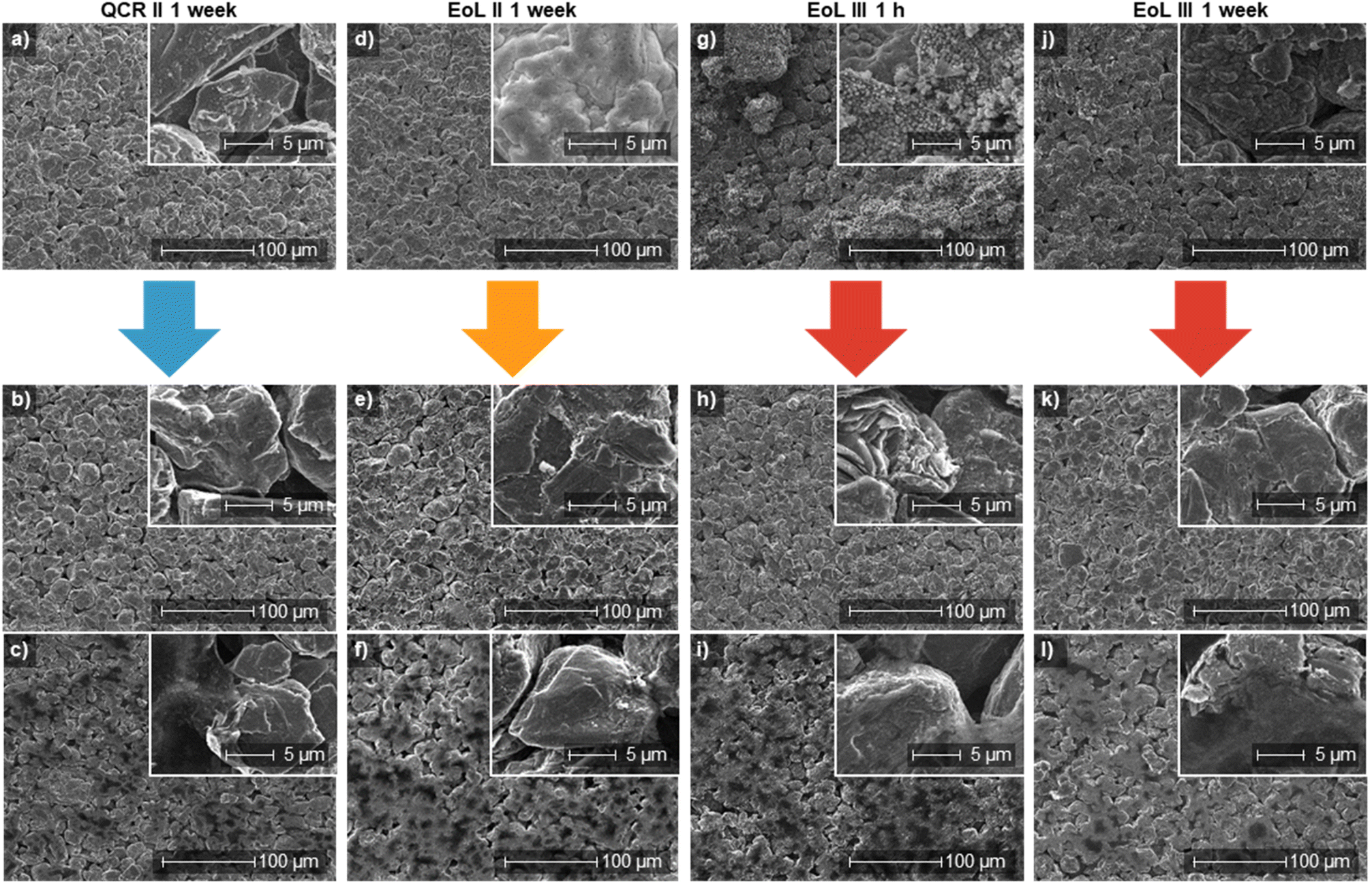
SEM images were used to study the effects of air exposure on the surface of the anodes. Images taken after 1 h, 24 h and 1 week of air exposure are shown in Fig. 2. The large “potato”-like particles indicate the use of sphericalised graphite in the anodes; these are also consistent in size including when comparing different anodes. QCR and QCR II show no noticeable changes in their surfaces after increased exposure to air; with the shape and surface texture remaining consistent for all images. Significantly, visible strata and a crystalline surface would be expected on the surface of particles, which was not seen on QCR and QCR II, and therefore a surface film may be present. This is likely to be components from the SEI layer and therefore a combination of organic and inorganic species, however, this could also be the pitch coating added to reduce first-cycle capacity loss. | ||
| Fig. 2 SEM images taken at either 5000× or 2500× magnification. (a–c) QCR after 1 h, 24 h and 1 week of air exposure, respectively. (d–f) QCR II after 1 h, 24 h and 1 week of air exposure, respectively. (g–i) EoL after 1 h, 24 h and 1 week of air exposure, respectively. (j–l) EoL II after 1 h, 24 h and 1 week of air exposure, respectively. (m–o) EoL III after 1 h, 24 h and 1 week of air exposure respectively. | ||
After 1 hour of air exposure all EoL anodes showed a highly contaminated surface, either showing small clusters of small particles (EoL shown in Fig. 2g and EoL III in Fig. 2m) or a thick, cracked crust again made out of an agglomerate of small particles (EoL II in Fig. 2j). Unlike the QCR anodes, these surfaces changed with increased air exposure time. The agglomeration of particles enlarged with increased time causing them to join and form a thick coating on the surface of the graphite. After 1 week, graphite particle boundaries were hard to distinguish on all EoL anodes (Fig. 2i, l and o). Of particular interest is EoL II (Fig. 2j–l), where the cracks in the crust shown after 1 hour slowly filled to form a coating that completely encased the graphite after a week of exposure.
The differences in reactivity between EoL and QCR anodes may originate from the increased complexity of carbon species shown within the XPS (Fig. 1a–e). These can react with the air to deposit material on the surface of the anodes and form more carbonates and ethers.41 Lithium containing species within the SEI are also likely to form more stable inorganic compounds like lithium carbonate and lithium hydroxide.41
Lithiated graphite, identified in XPS measurements, will react with the air and moisture via a number of oxidation and hydrolysis reactions, depositing a number of Li salts on the surface like LiOH, Li2O and Li2CO3. These lithium compounds are likely to form on the surface of the graphite, underneath the coatings shown within the SEM images, similar to what was observed by Malmgren et al.41
Water delamination
Submersion into water was conducted on anodes exposed to air for 1 h, 24 h, 2 weeks and 4 weeks. The following describes the reactivity of each anode and Fig. 3 shows a visual representation of the results. | ||
| Fig. 3 A visual representation of the efficiency of delamination for each sample after certain periods of air exposure. The solid filled block represents delamination that occurred before 10 min of water submersion. The lightly filled blocks represent delamination that required a submersion of over 10 min in water and often required the AF to be scraped off the current collector. The end of the blocks show the longest period of air exposure that still led to delamination. Exposure times above 4 weeks were not studied, therefore, EoL and EoL III may still delaminate at further periods of air exposure. | ||
After 1 h of air exposure all films delaminate from the current collector. All anodes also delaminated after an air exposure time of 24 h, however QCR took almost 2 h of submersion to delaminate compared to a delamination of under 5 min shown by QCR II, EoL, EoL II and EoL III. After being left out for 2 weeks, all anodes could still be delaminated except for QCR. After 4 weeks QCR II and EoL II would also now not delaminate. For all samples it was found that the effectiveness (whether it came off instantly in one sheet or had to be scraped off) decreased with increased air exposure time.
Furthermore, increasing the air exposure time resulted in less rapid delamination: delamination of EoL within 1 h took under 10 s, with both sides coming off as sheets; after 4 weeks the process required just under 2 h and one side had to be scraped off.
Fig. 4 shows the delamination of an entire anode sheet of EoL within 1 h of air exposure. A video of this process is given within the ESI.† The entire process of removing the AF from the current collector took 3 min with the delamination beginning at around 10 s. Efficient delamination causes the film to come off as a sheet as shown in Fig. 4, this may occur as the PVDF binding is weakest at the boundary between the current collector and the AF.48
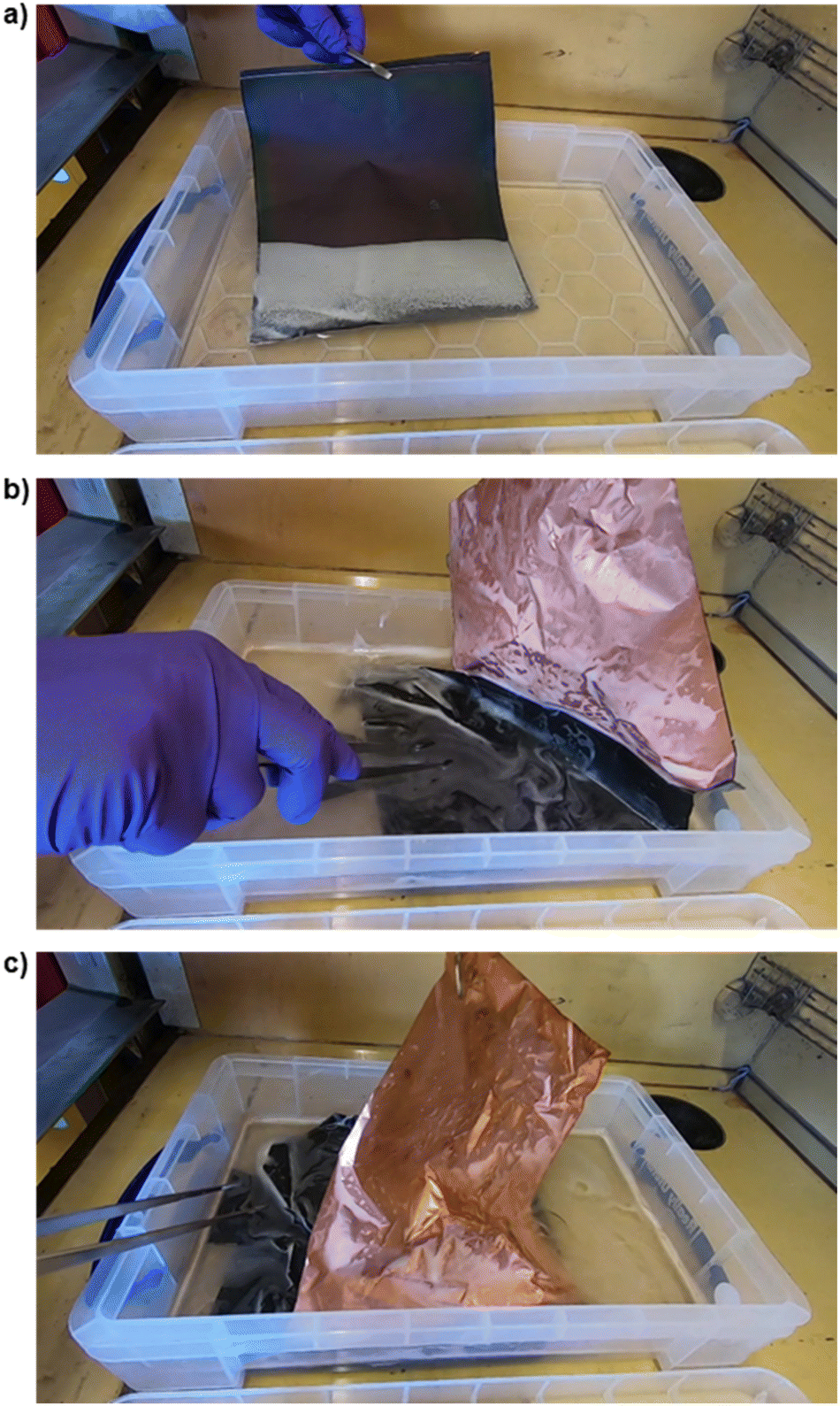 | ||
| Fig. 4 Snapshots of a video (given within the ESI†) of the delamination of a full anode sheet of EoL material using 450 ml of deionised water. The EoL sheet was washed with DMC in a glovebox and only exposed to air for less than 1 h before submerging in water. The whole process took approximately 3 min however the material began to delaminate within 10 s. (a) Upon submerging the EoL anode, effervescence was observed. (b) Displays the peeling off of one side of active material, exposing the clean surface of the copper current collector. (c) Active material peeling of the reverse side. | ||
For each sample, the pH change in the water used for delamination remained fairly consistent after different exposure times (increasing from pH 6 to around pH 9) however the amount of effervescence observed decreased with decreased effectiveness (i.e. for the sheets left in air for longer durations). The delamination process and associated effervescence is assigned to reaction of trace amounts of lithiated graphite within the anodes, as identified by XPS. Upon submersion into water, this will hydrolyse, including, but not limited to the reaction schemes given below:
| 2LixC(s) +2XH2O(l) → 2C(s) + 2XLiOH(aq) + XH2(g) | (1) |
| 2LixC(s) + 2CO2(g) + 2H2O(l) → 2C(s) + 2LiHCO3(aq) + H2(g) | (2) |
| 2LiHCO3(aq) → Li2CO3(aq) + H2O(l) + CO2(g) | (3) |
The formation of H2 gas from the hydrolysis may provide enough energy via local cavitation to cleave the AF from the current collector. This delamination would be similar to ultrasonic delamination, where bubbles form local regions of high pressure that can break the binder and release the AF.4,60
ICP-OES analysis was conducted on the water after 1 h of submersion of each sample. The results from the 610.365 nm Li line are shown in Fig. 5. Concentrations of manganese, copper, cobalt and nickel were also examined, however values above 0.5 ppm were not observed for these elements and these metals were therefore concluded not to influence the delamination process. The results show that the concentration of Li within the water after submersion of anodes increases with a trend of QCR < QCR II < EoL < EoL II < EoL III. The higher concentrations from EoL anodes are likely to be due in part to the increased thickness of the SEI layer that grows during cycling. Other than SEI growth, lithium inventory loss during cycling can occur through a number of other processes including: lithium plating and trapping of lithium-ions as lithiated graphite within electronically-isolated particles due to cracking, loss of contact or blocking of active sites.61 All these factors will be more severe in EoL anodes and likely contributes to the observed trend in lithium concentrations.61,62
 | ||
| Fig. 5 Li concentrations within 20 ml of water after the submersion of each anode for 1 h after either 1 h, 24 h, 2 weeks or 4 weeks of air exposure. Each anode was cut into a 10 mm disk weighing approximately 0.2 g. The 610.365 nm analytical line for lithium was used. Error bars represent the standard error after three repeated measurements of the same solution. | ||
Li concentrations within the solutions after delamination of each sample after differing air exposure times remain consistent. The congruent agreement in Li concentrations but loss in delamination effectiveness after increased air exposure time may correspond to the formation of LiOH/Li2CO3 on the surface (through the hydrolysis of lithiated graphite with the moisture in air) that is still dissolvable when submerged in water but would not produce the needed effervescence (and hence cavitation) caused by the H2 production.
Study of the recovered anode film
Raman spectroscopy was used to study the nature of the AF before and after water submersion. Fig. 6 displays Raman spectra of QCR II and EoL II. Other sample spectra are given within the ESI (Fig. S3†). Expanded regions of interest and labelled peaks are given in Fig. 6e–h. As expected, the spectra are dominated by graphitic peaks, specifically the G (graphite) band found at 1590 cm−1 and the D (disorder) band at 1320–1440 cm−1.63–66 The G band can be easily resolved by fitting a Lorentzian peak, however for this study the D band was resolved using three Voigt peaks, combining the D, D3 and D4 peaks assigned in literature into one disordered region.66 The G′ region found between 2500–2800 cm−1 has previously been used to investigate the degree of stacking between the graphene layers.63,67 However, due to the bulk nature of the sample and complexity of the G′ region, which will also be influenced by the presence of carbon black, analysis of the G′ peaks was not carried out. Two overlapping broad peaks centred at 800 cm−1 for both samples appear after water submersion (in Fig. 6b, d and an expanded region is shown in Fig. 6f). These are assigned to amorphous sp2 vibrations from pitch-derived carbon coatings on the surface of the graphite which is exposed when the SEI is removed.68,69 These two peaks were also found in the Raman spectra taken for virgin MAGE3 graphite, shown in Fig. S4,† which is also likely to have this pitch-derived carbon coating. In EoL II before water submersion (Fig. 6c) and to a lesser extent the same sample after water submersion (Fig. 6d), three intense peaks at around 422.6, 471.8 and 596.1 cm−1 can be observed (highlighted in Fig. 6e). In the literature, PO4 ν2 symmetric bending generally appears at around 431 cm−1 and PO4 ν4 asymmetric bending at around 594 cm−1, suggesting that the observed peaks are due to the presence of a phosphate salt.70 Multiple phosphate products could appear on the surface after air exposure including manganese phosphate, nickel phosphate, organic phosphates and organo-fluoro-phosphates, either from the presence of manganese, nickel, SEI or trace electrolyte.71 However, the complexity of the surface makes it almost impossible to confirm the identity of these peaks; as well as phosphates, multiple lithium salts like Li2O and LiOH produce peaks in this region.72 A small sharp peak appears between 950–1085 cm−1 in Fig. 6c which has been associated with Li2CO3.73 A small peak intermittently appears at around 1753 cm−1 and may correspond to 2ν2 overtones of internal vibrations within CO32− groups.74 This could be linked to the presence of Li2CO3 or MnCO3 on the surface. The intensity and presence of these impurity peaks vary between scans on the same sample at the same air exposure period. This conveys that the surface is not homogeneous which in itself could suggest that aging occurs in local clusters and not evenly within a battery. Submersion of EoL II in water appears to remove most of these impurities, however some traces still remain.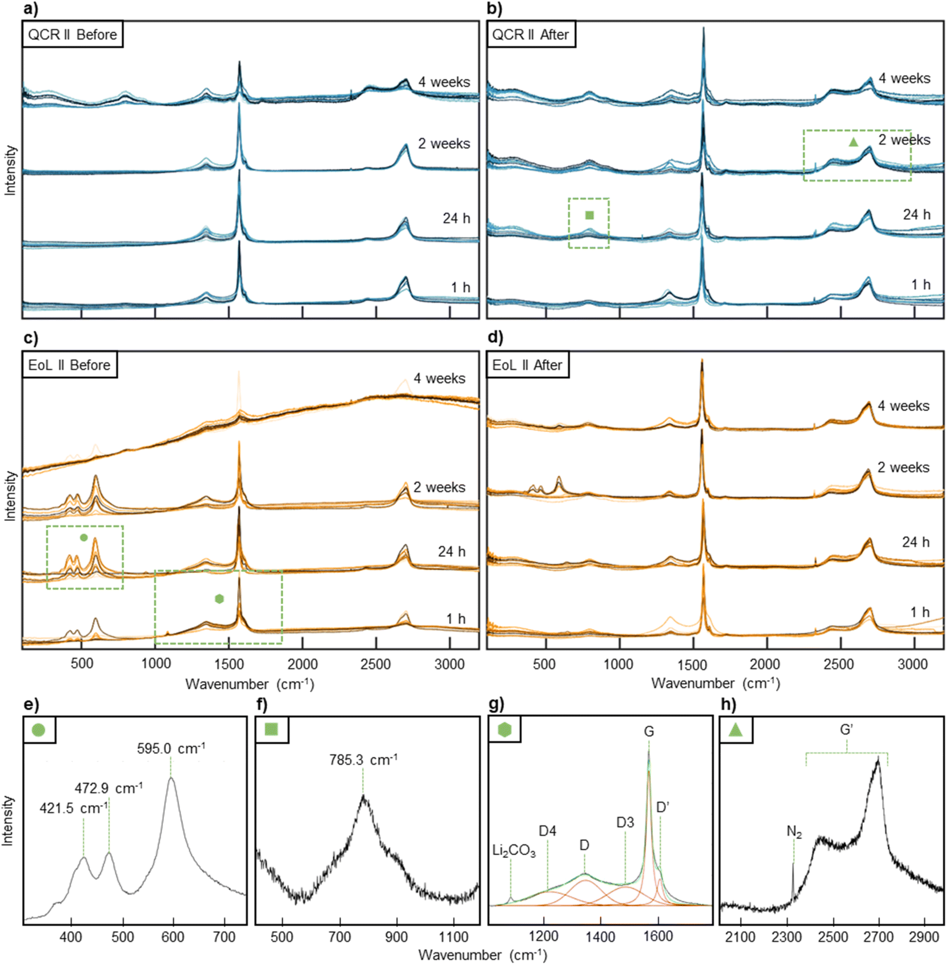 | ||
| Fig. 6 10 Raman spectra were taken after certain periods of air exposure for (a) QCR II before water submersion and (b) after water submersion. The same was done for (c) EoL II before water submersion and (d) after water submersion. The 10 scans were taken from random positions on the sample to represent the full surface and are shown overlapping in the figure. This results in 40 scans for each sample. (e–h) displays regions of interest from the Raman spectra shown in (a–d). The areas they originate from are highlighted with a green box and a symbol used as an identifier. (e) Phosphorous or lithium salt peaks found between 300–750 cm−1 in EoL II with an air exposure of 24 h. (f) Amorphous sp2 vibrations found between 600–1200 cm−1 for QCR II after 24 h of air exposure and water submersion. (g) The graphitic region found between 1100–1700 cm−1 for EoL II after 1 h of air exposure. Graphitic peak fittings are shown and labelled, as well as the peak originating from Li2CO3. (h) The G′ region found between 2000–3000 cm−1 for QCR II after 2 weeks of air exposure and water submersion. | ||
The D region equates to the presence of defects within the graphite, allowing for theoretically disallowed phonons within a perfectly stacked crystalline graphite, whereas the G band corresponds to a stretching mode of E2g symmetry within sp2 sites and will appear in even the most crystalline of graphite.63,65,66 Thus, the ID/IG ratio, taken using the integrated intensity of the G and D bands, can be used to quantify the amount of disorder, with a higher value representing a larger number of defects at the near-surface of the particles.
Traditionally single point scans are used to identify the ratio, however this may introduce uncertainty due to the local nature of defects within graphite.75,76 It is evident from Fig. 6 that the intensities of the D and G bands change on the same sample at different positions. Therefore, a statistical approach was taken gathering Raman features from a large area and plotting a distribution to convey the global quality of the AF. Fig. 7a to j displays these distributions before and after water submersion.
For QCR and QCR II, skewed distributions with mean ID/IG values of 0.84 and 1.03 are obtained before water submersion (shown in Fig. 7a and b). These appear far less disordered than the EoL materials showing broader distributions (indicating a less homogeneous surface) and mean values of 2.08, 2.41 and 2.77 for EoL, EoL II and EoL III respectively (Fig. 7c–e). After submersion in water (shown in Fig. 7f–j), all distributions skew to lower ID/IG values, with EoL, EoL II and EoL III all showing a significant change. Mean values of 1.10, 0.66, 0.49, 0.53 and 1.48 were obtained for QCR, QCR II, EoL, EoL II and EoL III, respectively. Raman spectroscopy is a surface/sub-surface analytical technique, and therefore the increase in graphitic nature in the EoL materials may be associated with a loss of SEI remnants and organic products from the surface. The graphite itself seems relatively unaffected by progressive battery cycling given that the Raman spectra of reclaimed samples with SEI removed look very similar. This suggests that aging in these cells results mainly from continuous SEI production causing both Li loss and increased resistance, and also metal migration or electrolyte decomposition. Therefore, once processed, recycled graphite from used batteries may be structurally similar to virgin material. EoL III has the highest mean ID/IG ratio after water submersion (1.48), meaning that the graphite from EoL III is more disordered than the others, potentially caused by the battery hitting the failure knee point near the end of its cycle life. A higher mean ID/IG ratio was also observed for QCR.
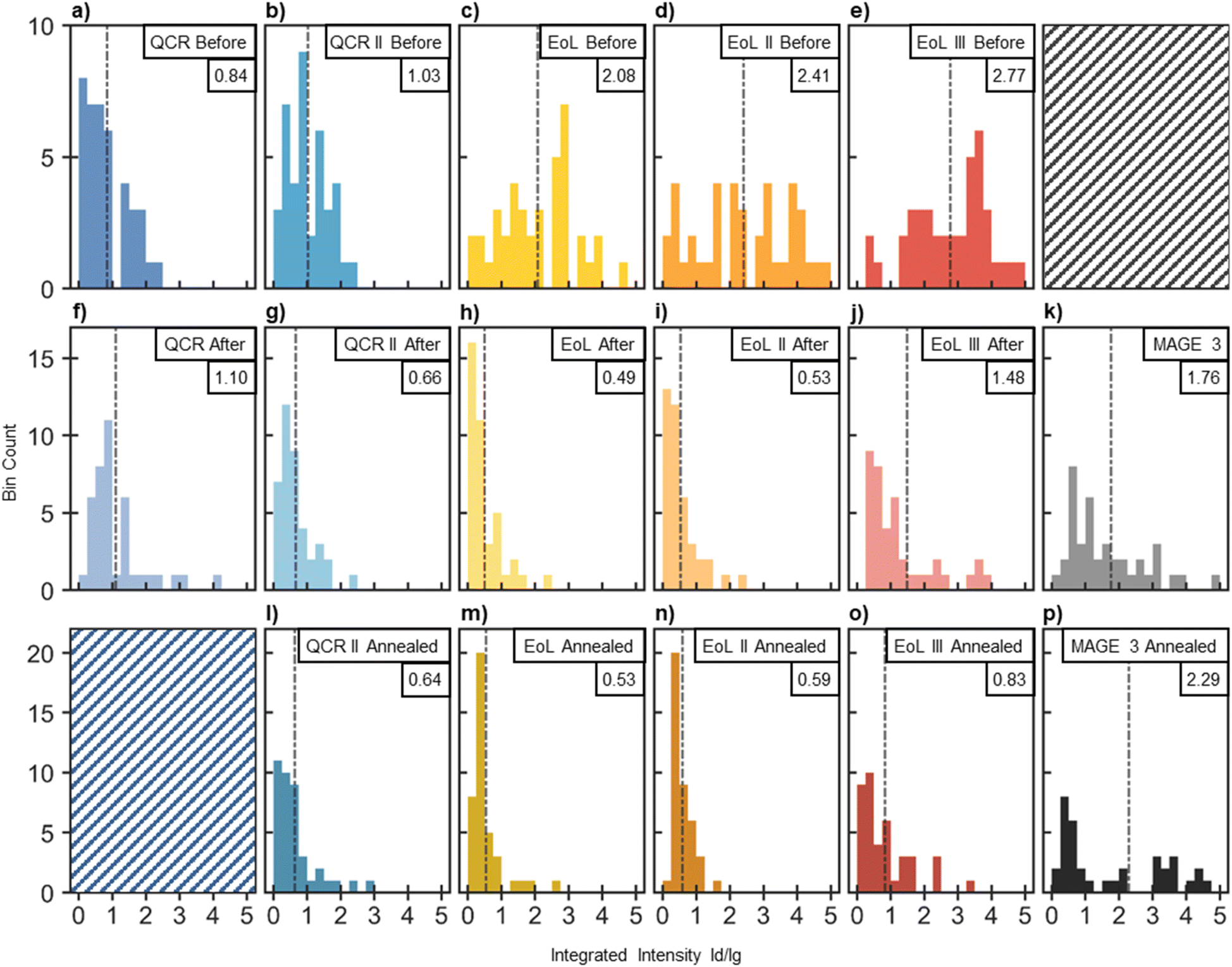 | ||
| Fig. 7 Distribution of 40 ID/IG ratios taken from Raman scans distributed randomly on the sample. ID/IG ratios were obtained using a peak-fitting algorithm created in MATLAB. The integrated intensities of all peaks within the D region were compared to the integrated intensity of the G peak. The mean ID/IG ratio is shown by the dash-dotted black line and is given in the top right corner of each distribution. (a–e) Distributions of (from the left): QCR, QCR II, EoL, EoL II and EoL III before water submersion. 10 scans were taken at each of the following air exposure times: 1 h, 24 h, 2 weeks and 4 weeks and combined to form the distribution. (f–j) Distributions of (from the left): QCR, QCR II, EoL, EoL II and EoL III after water submersion. Water submersion was conducted at the following air exposure times: 1 h, 24 h, 2 weeks and 4 weeks, after which 10 scans were taken of each and combined to form the distribution. (k) Distribution obtained after 40 scans on a sample of MAGE3 powder. (l–o) Distributions obtained for QCR II, EoL, EoL II and EoL III respectively after annealing each AF to 500 °C for 1 h. For each sample, 20 scans were taken on the annealed AF that was delaminated after 1 h of air exposure and the other 20 were taken on the annealed AF obtained after 2 weeks of air exposure. (p) A distribution obtained after 40 scans on a powder of MAGE3 that was annealed to 500 °C for 1 h. | ||
SEM images of QCR II, EoL II and EoL III before and after delamination are shown in Fig. 8 (images for other AF can be found in Fig. S5†). The surface coating from oxidised SEI can be seen in Fig. 8d, g and j, made up of clusters of agglomerates on the surface, encasing the graphite particles. Fig. 8e, h and k show the water-delaminated samples, demonstrating that the delamination procedure does not just remove the AF from the current collector, but also appears to remove this coating, exposing the surface of the graphite particles. This is consistent with the Raman data (Fig. 7) as the surface is seen to be cleaner and more graphitic after delamination. Removal of SEI traces would be beneficial for the second-life electrochemical use of graphite, as if left it creates a larger, more reactive, inhomogeneous surface for more SEI growth during the first-cycle. The leftover SEI may also add more resistivity.
 | ||
| Fig. 8 Large SEM images at 250× magnification with a 5000× magnified SEM image in the top right of each. (a) QCR II after 1 week of air exposure. (b) Water-delaminated QCR II after 2 weeks of air exposure, showing the face that originally faced the separator and electrolyte. (c) Water-delaminated QCR II after 2 weeks of air exposure, showing the face that was attached to the current collector. (d–f) Similar to (a–c) however for EoL II after 1 week of air exposure for the top image and delamination after 2 weeks for the bottom two. (g–j) Showing EoL III after 1 hour of air exposure and delamination after the same time period. (j–l) EoL III after 1 week of air exposure and delamination after 2 weeks. | ||
When the delamination happens quickly, i.e. on samples exposed only briefly to air, the AF separates from the current collector as a sheet. Therefore the sample has two sides: the side that faced the electrolyte and the side that faced the current collector. The former are shown in Fig. 8b, e, h and k and the latter in Fig. 8c, f, i and l for the four samples. The sides that faced the current collector shows pooling of an organic substance between the particles of graphite; energy dispersive X-ray spectroscopy (EDX) (Fig. S6†), shows these regions contain high concentrations of fluorine, presumably due to the presence of PVDF binder. Concentrating PVDF closer to the current collector by using low drying temperatures is typically used to provide better adhesion between the AF and the current collector, and this concentration gradient is retained during the delamination process.77,78
Delamination of QCR II (Fig. 8b), EoL II (Fig. 8e) and EoL III (Fig. 8k) after 2 weeks provide graphite particles with no obvious degradation/exfoliation. The compact, sheet-like formation of the materials suggests that PVDF still holds the recovered AFs together. SEM images taken after the delamination of EoL III within 1 h of air exposure (Fig. 8h) show a small percentage of the recovered graphite that has lost it's sphericalised shape. This may likely be caused by the localised conditions of H2 production when submerged in water. However, this was only observed on EoL III with 1 h of air exposure.
Annealing the anode film
The remaining PVDF content in the AFs would reduce the specific capacity if used in a newly constructed cells, while the sheet-like nature of the collected material would also be impractical for formulation into new coatings. Therefore annealing of the graphite was investigated to remove PVDF and any residual SEI or oxidised residue which was not removed during the reclamation process.65 Heating to a temperature of 500 °C in air for a duration of 1 h was chosen for samples delaminated after 1 h and two weeks of air exposure. Sample QCR was not annealed due to the difficulty in delaminating it from the current collector.The short time-frame used for the annealing meant that the technique for obtaining second use material was still quick and low cost, in contrast to the formation of synthetic graphite which can require a temperature of 2500 °C for several days.79
PVDF is known to act as a fluorinating agent when heated with various metal oxides due to its thermal breakdown into HF and various fluorine monomers which will then further breakdown into CO, CO2 and more HF.80 Fluorination of graphite however, requires the use of fluorine gas and as this is not a decomposition product of PVDF, no fluorination was expected.81–83
The SEM images of the one hour air-exposed delamination products after annealing, compared to MAGE3, are shown in Fig. 9. The annealed two week air-exposed delaminated samples are shown within the ESI (Fig. S7†).
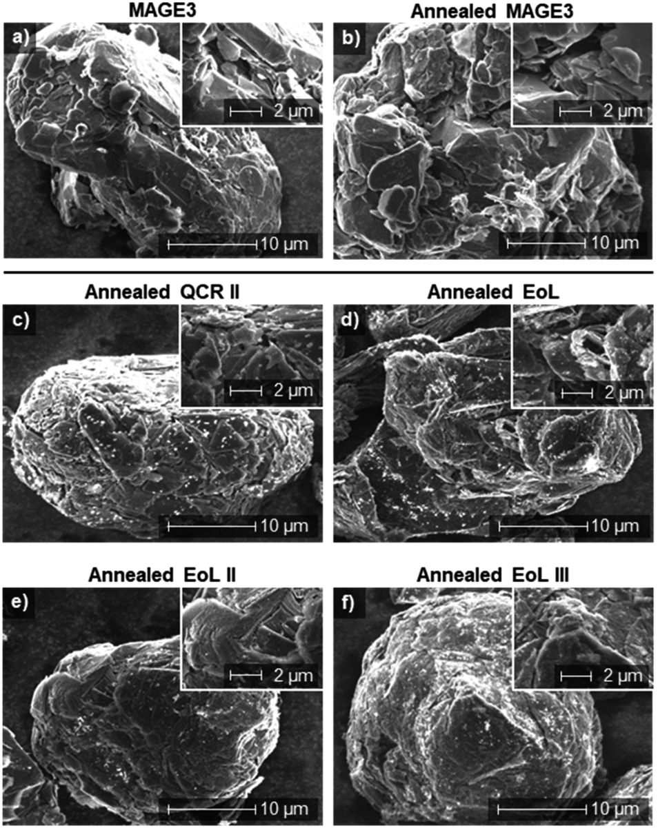 | ||
| Fig. 9 Large 5000× magnified SEM images with 12000× magnified SEM images in the top right of each. (a) MAGE3 particle. (b) A particle of MAGE3 after annealing to 500 °C for 1 h. (c) QCR II (d) EoL (e) EoL II (f) EoL III. All AF were delaminated after 1 h of air exposure and annealing to 500 °C for 1 h. | ||
After annealing, AFs became powdered, consistent with the removal of PVDF and the observation in SEM (Fig. 9) that graphite particles from all AFs had separated. Furthermore, on the surface of the particles, layers and flakes of graphite can be observed, suggesting that any coating that remained on the surface had been removed. In comparison to MAGE3 (Fig. 9a) the size and shape of the recovered graphite are very similar to that of virgin material. However, the recovered graphite particles appear to comprise of compact clusters with jagged-edges and visible strata whereas the MAGE3 samples comprise of smooth, smooth-edged pieces clustered together. These differences could originate from the types of graphite used, with the more isotropic nature of MAGE3 suggesting a synthetic origin and the anisotropic crystaline plates of the recovered graphite suggesting an origin from mined natural graphite.79
Apparent agglomerates appear as white specs on the surface of all recovered graphite with QCR II (Fig. 9c) having the highest concentration.65 These contaminants could form as a consequence of heating PVDF, SEI species or could be lithium or metal salts. EDX analysis of annealed EoL III (after one hour and two weeks of air exposure before delamination) are given within the ESI (Fig. S8†). These show that impurities in the recovered graphite contain traces of manganese and fluorine. It may be noted that the presence of nickel was not detected. A comparison of MAGE3 (Fig. 9a) to annealed MAGE3 (Fig. 9b) shows that the annealing process does not appear to affect the surface structure or morphology of the graphite particles.
Raman spectroscopy distributions of annealed samples (Fig. 7l to p) showed no discernible changes in ID/IG mean values after annealing; however, distributions were noticeably narrower. This suggests that while the overall ordering has not increased, the homogeneity of the samples have. EoL III does show an increase in ordering with a decrease of the average ID/IG ratio from 1.48 after delamination to 0.83 after annealing. It is possible that the higher surface area of the de-sphericalised graphite caused these to combust, leaving only the higher ordered, sphericalised graphite.84
Raman spectra of each recovered graphite sample are shown within the ESI (Fig. S9†) and show small traces of heterogeneous contamination from salts that could affect the electrochemical performance.
Electrochemical performance
Electrochemical testing within lithium ion half cells was conducted on the graphite samples obtained after the annealing of recovered AFs (1 h and 2 week air exposed samples), with MAGE3 for comparison.All recovered graphite showed stable specific capacities close to the theoretical capacity for graphite and exceeding the MAGE3 standard (Fig. 10a). The biggest drop in specific capacity for all cells occurred between cycle 5 and 6, which is due to the electrode polarization caused by the switch to a higher cycling rate of C/5.
 | ||
| Fig. 10 (a) Graphite discharge specific capacities plotted against cycle number for Li metal half-cells (using graphite obtained after water delamination and subsequent annealing). 1 h and 2 weeks refer to the time exposed to air before delamination. MAGE3 was used as a standard, representing virgin commercial material. Each data point represents the average of measurements made from three half cells. The first 5 cycles were run at C/20 (18.6 mA g−1) then the remaining 15 were run at C/5 (74.4 mA g−1) using 372 mA h g−1 as the theoretical capacity. The grey dotted line represents the theoretical capacity. (b) Coulombic efficiency against cycle number for each obtained graphite and MAGE3. Each point is an average made up of three half cells and the error bars consist of the 95% confidence interval. | ||
The electrochemical profiles of the recovered materials given within the ESI (Fig. S10–S13†) resemble those of pristine graphite (Fig. S14†), indicating no significant change to the graphite structure in agreement with SEM and Raman data.
Active mass loading and anode thickness (found in Table 2) can be linked to changes in specific capacity between the cells of each recovered graphite. For example, EoL III 1 h has the highest capacity and EoL II 2 w the lowest, which correlates to the active masses of 3.1 mg cm−2 for EoL III 1 h and 6.3 mg cm−2 for EoL II 2 w. However, the MAGE3 coating used sits comfortably within this range of active mass loadings but cycling shows lower specific capacities than any of the recovered graphite.
Fig. 10b shows no distinct differences in the coulombic efficiency (CE) between any of the cycled cells. Values appear to vary steadily around an excellent value of 99.9% for all cells after the initial formation cycles. The low CE at the start of each cells cycling and the large first cycle capacity loss in Table 5 are associated with the initial formation of the SEI.85 The CE of the recovered graphite cells match that of the MAGE3, therefore it can be concluded that irreversible reactions or self-discharging within MAGE3 cells are not responsible for the differences in specific capacity.86,87 The larger domain sizes of natural graphite typically provide higher specific capacities than synthetic graphite.79 This may explain the differences in specific capacity between the recovered graphite and MAGE3.
| Graphite used | First cycle charge capacity (mA h g−1) | First cycle discharge capacity (mA h g−1) | First cycle irreversible capacity loss | C/20 to C/5 capacity loss | Capacity loss after 20 cycles | |||
|---|---|---|---|---|---|---|---|---|
| mA h g−1 | % loss | mA h g−1 | % loss | mA h g−1 | % loss | |||
| QCR II 1 h | 382.6 ± 5.8 | 356.5 ± 8.1 | 26.1 ± 3.3 | 6.8 ± 0.9 | 25.0 ± 0.3 | 6.5 ± 0.1 | 34.3 ± 8.9 | 9.0 ± 2.2 |
| QCR II 2 weeks | 387.7 ± 8.3 | 358.0 ± 5.9 | 29.7 ± 2.5 | 7.7 ± 0.5 | 20.9 ± 0.9 | 5.4 ± 0.2 | 35.4 ± 7.0 | 9.1 ± 1.6 |
| EoL 1 h | 388.9 ± 17.6 | 359.9 ± 22.4 | 29.0 ± 5.2 | 7.5 ± 1.7 | 41.5 ± 1.9 | 10.7 ± 0.5 | 39.3 ± 16.3 | 10.1 ± 3.9 |
| EoL 2 weeks | 397.6 ± 7.8 | 366.9 ± 7.9 | 30.7 ± 0.5 | 7.7 ± 0.2 | 30.0 ± 0.1 | 7.5 ± 0.0 | 58.8 ± 6.2 | 14.8 ± 1.4 |
| EoL II 1 h | 400.9 ± 4.1 | 370.4 ± 0.4 | 30.5 ± 3.3 | 7.6 ± 0.9 | 41.4 ± 2.8 | 10.3 ± 0.7 | 60.2 ± 7.1 | 15.0 ± 2.0 |
| EoL II 2 weeks | 397.1 ± 3.5 | 363.7 ± 4.1 | 33.4 ± 0.7 | 8.4 ± 0.2 | 38.2 ± 0.7 | 9.6 ± 0.2 | 71.1 ± 4.8 | 17.9 ± 1.1 |
| EoL III 1 h | 404.2 ± 4.3 | 371.0 ± 3.8 | 33.2 ± 0.4 | 8.2 ± 0.0 | 33.5 ± 0.8 | 8.3 ± 0.2 | 71.0 ± 4.9 | 17.6 ± 1.4 |
| EoL III 2 weeks | 415.3 ± 3.2 | 375.4 ± 3.0 | 40.0 ± 0.2 | 9.6 ± 0.0 | 17.8 ± 0.4 | 4.3 ± 0.1 | 56.7 ± 3.2 | 13.6 ± 0.8 |
| MAGE3 | 370.9 ± 12.9 | 342.9 ± 11.7 | 27.9 ± 1.4 | 7.5 ± 0.2 | 6.3 ± 0.3 | 1.7 ± 0.1 | 67.2 ± 6.0 | 18.1 ± 1.2 |
Evidently in the short term, the contamination on the graphite surface does not affect the electrochemical performance of the recovered graphite and excellent specific capacities are achieved.
Further studies probing long-term cycling performance were conducted on the recovered graphite from EoL III (∼30% of the original capacity before dismantling). Asymmetric cycling for 200 cycles (charged at C/2 (186 mA g−1) and discharge with 1C (372 mA g−1)) was conducted on annealed EoL III samples water delaminated after 1 h and 2 weeks of air exposure. These results are compared to MAGE3 in Fig. 11. The recovered graphite performs at much higher specific capacities than MAGE3 for all cycles, with EoL III 2 weeks showing higher capacity than EoL III 1 h. After 200 cycles EoL III 1 h retained a specific capacity of 94.4 mA h g−1 and EoL III 2 weeks and MAGE3 retained 139.6 mA h g−1 and 59.3 mA h g−1 respectively. The significantly improved performance for the recovered graphite compared to MAGE3 may result from the graphite sourced from dismantled cells previously being optimised for higher currents, whereas MAGE3 is known to underperform at higher current rates.85 All cells experience a dip in capacity between cycle 1 and 40, assigned to non-optimised formation cycles leading to unstable SEI. The recovered graphite shows large variance between each cell, resulting in large error bars for EoL III 1 h and EoL III 2 weeks. This may potentially be due to metal salt impurities left on the graphite, where the inhomogeneity of the contamination leads to a variance in the cells electrochemical performance at higher rates. These results highlight that further optimisation of the delamination process may be possible in order to optimise the long-term cycling performance.
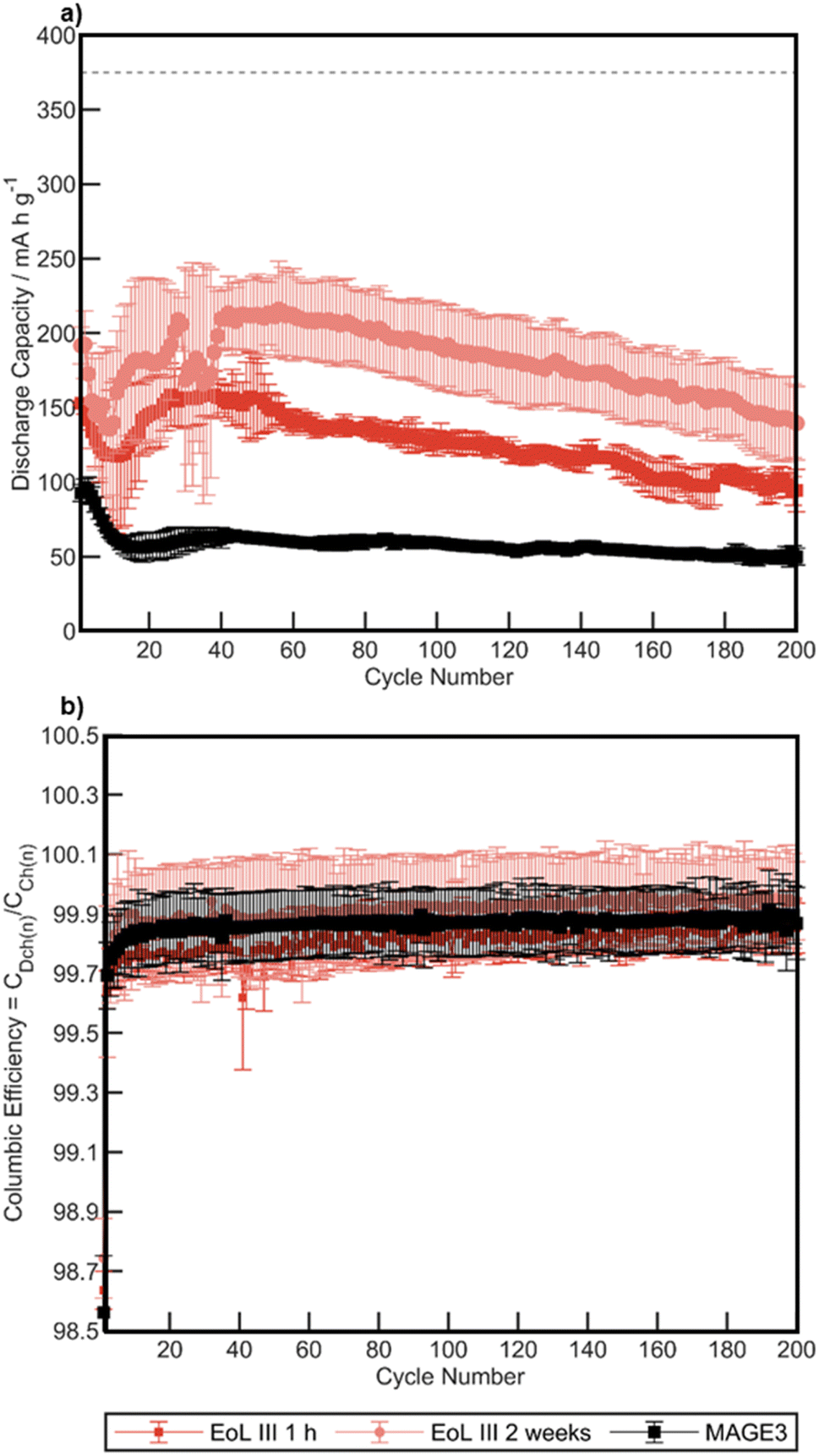 | ||
| Fig. 11 (a) Graphite discharge specific capacities plotted against cycle number for triplicate Li metal half-cells made from EoL III recovered graphite and MAGE3. 1 h and 2 weeks refer to the time exposed to air before delamination. 200 asymmetrical cycles were conducted with a charge rate of C/2 (186 mA g−1) and discharge of 1C (372 mA g−1) after two initial formation cycles at C/20 (18.6 mA g−1) that were omitted from the figure. (b) Coulombic efficiency against cycle number for each EoL III recovered graphite and MAGE3. Each point is an average and the error bars consist of the 95% confidence interval. | ||
Water delamination as a recycling technique
The delamination technique presented here utilises the inherent reactivity of lithiated graphite to achieve the simplest possible, all-in-one delamination and washing technique for lithium-ion anode electrodes. This should minimise cross contamination risks from shredding and the hazards and cost of alternative solvents for delamination. The graphite obtained demonstrates promising electrochemical performance compared to literature,88 although long-term asymmetric cycling studies at high current densities suggest that performance may be affected by both air exposure time and local contaminants; thus, further optimisation of the reclamation is likely to be required, particularly to balance between the ease of reclamation and electrochemical performance. This mechanism of delamination also provides an additional advantage in terms of lithium recovery, as water submersion results in a lithium containing solution which can be further concentrated for lithium recovery and reuse.Conclusions
A simple, low-cost method for extracting graphite from first-generation anodes with PVDF binder has been demonstrated on a range of materials including quality-control reject and end-of-life material from an electric vehicle. Once extracted from a cell and washed with DMC, anodes can be taken out of an inert atmosphere, and upon submersion in water, trace amounts of lithiated graphite will react to form hydrogen. The local cavitation caused by the hydrogen formation levers the anode film away from the current collector causing it to separate. Increased exposure to air decreases the effectiveness of the delamination, such that after 4 weeks only two of the samples delaminated (EoL and EoL III).XPS, Raman spectroscopy and SEM images were used to analyse the quality of the obtained anode films after delamination and the recovered graphite after low temperature heat treatment. These revealed the presence of manganese and nickel, as well as the growth of agglomerates on the surface of the graphite from species within the SEI reacting with air/moisture. However, it was found that most of the contaminants could be removed via the water delamination process. PVDF was still present after water delamination, however, subsequent annealing to 500 °C for 1 h successfully removed the PVDF as well as slightly increasing the ordering of the graphite surface through the removal of surface groups and defects.
Electrochemical testing revealed that the recovered graphite displayed close to the theoretical capacity of graphite, surpassing the performance of a commercial electrochemical grade graphite standard under similar conditions. Asymmetric testing was also conducted, obtaining specific capacities of 94.4 mA h g−1, 139.6 mA h g−1 and 59.3 mA g−1 for EoL III 1 h, EoL III 2 weeks and MAGE3 after 200 cycles at C/2 and 1C. However, the obtained graphite showed variance in its performance, likely due to inhomogeneous impurities.
Overall, these results highlight that, through optimisation of the reclamation processes, EoL anodes can provide a source for high performing electrochemical graphite helping secure future supplies of this critical raw material and helping to alleviate concerns over future accumulation of battery waste.
Data availability
The data associated with this paper are openly available from: https://doi.org/10.25500/edata.bham.00000908.Author contributions
ATS, PKA, PRS, EK and PAA designed the project. ATS, PKA, PRS planned experiments, interpreted data and wrote the manuscript. ATS performed experiments and data analysis. ZH, ASW, BFS, WRF performed XPS/HAXPES measurements. LS undertook data interpretation of Raman data. All authors contributed to writing, reviewing and editing the manuscript.Conflicts of interest
There are no conflicts to declare.Acknowledgements
This work was supported by the Henry Royce Institute, funded through EPSRC grants EP/R00661X/1, EP/P025021/1 and EP/P025498/1 as well as the Faraday Institution ReLIB project FIRG005 and FIRG027, and CATMAT (FIRG016) and nextrode (FIRG015) projects. The author would like to thank Rob Sommerville and Anton Zorin for dismantling the pouch cells used in this study, and Abbey Jarvis for support during lab work and especially during ICP work.References
- S. Gifford, The Road to Electrification – from the Internal Combustion Engine to the Battery Electric Vehicle, Faraday Insights, 2019, 1, 1–4 Search PubMed.
- N. Morris, I. Ellerington, A. Paterson, M. Howard and S. Gifford, UK electric vehicle and battery production potential to 2040, Faraday Institution, 2020 Search PubMed.
- T. Parry and S. Reynolds, Vehicle Licensing Statistics: Annual 2020, Department for Transport, 2021 Search PubMed.
- C. Lei, I. Aldous, J. M. Hartley, D. L. Thompson, S. Scott, R. Hanson, P. A. Anderson, E. Kendrick, R. Sommerville, K. S. Ryder and A. P. Abbott, Green Chem., 2021, 23, 4710–4715 RSC.
- S. Gifford and R. Lee, The importance of coherent regulatory and policy strategies for the recycling of EV batteries, Faraday Insights, 2020, 9, 1–8 Search PubMed.
- RCS Global, The due diligence risk and impact from the upstream to the midstream, 2017, https://battery.rcsglobal.com/sourcing-risks/, accessed 12 May 2021 Search PubMed.
- J. Hu, J. Zhang, H. Li, Y. Chen and C. Wang, J. Power Sources, 2017, 351, 192–199 CrossRef CAS.
- J. Heelan, E. Gratz, Z. Zheng, Q. Wang, M. Chen, D. Apelian and Y. Wang, JOM, 2016, 68, 2632–2638 CrossRef CAS.
- J. Beddington, A. Walton, P. Anderson, A. Abbott, A. Bloodworth, D. OudeNijeweme, E. Schofield, F. Wall, G. Harper, N. Glover, R. Chaddock, R. Gross, R. Lee, R. Grimes, R. Lewis, V. Gibson, V. Mann, P. McGuiness and R. Ogrin, Securing technology-critical metals for Britain, 2021, DOI:10.25500/epapers.bham.00003450.
- X. Xia and P. Li, Sci. Total Environ., 2022, 814, 152870 CrossRef CAS PubMed.
- B. Huang, Z. Pan, X. Su and L. An, J. Power Sources, 2018, 399, 274–286 CrossRef CAS.
- S. M. Shin, N. H. Kim, J. S. Sohn, D. H. Yang and Y. H. Kim, Hydrometallurgy, 2005, 79, 172–181 CrossRef CAS.
- F. Stehmann, S. Jahnke, C. Balmforth-Slater and S. Scholl, J. Electrochem. Soc., 2017, 164, A622–A629 CrossRef CAS.
- H. Li, S. Xing, Y. Liu, F. Li, H. Guo and G. Kuang, ACS Sustain. Chem. Eng., 2017, 5, 8017–8024 CrossRef CAS.
- T. Georgi-Maschler, B. Friedrich, R. Weyhe, H. Heegn and M. Rutz, J. Power Sources, 2012, 207, 173–182 CrossRef CAS.
- L. Li, L. Zhai, X. Zhang, J. Lu, R. Chen, F. Wu and K. Amine, J. Power Sources, 2014, 262, 380–385 CrossRef CAS.
- R. Sommerville, P. Zhu, M. Ali, O. Heidrich, V. Goodship and E. Kendrick, Resour., Conserv. Recycl., 2022, 165, 105219 CrossRef.
- B. Moradi and G. G. Botte, J. Appl. Electrochem., 2016, 46, 123–148 CrossRef CAS.
- J. B. Dunn, L. Gaines, M. Barnes, J. Sullivan and M. Wang, Material and energy flows in the materials production, assemble, and end-of-life stages of the automotive lithium-ion battery life cycle, Argonne National Labratory, 2012 Search PubMed.
- A. Bennett, Graphite demand from EV battery sector forecast to rise over 35% in 2022, 2012, https://www.fastmarkets.com/insights/graphite-demand-from-ev-battery-sector-forecast-to-rise-over-35-in-2022, accessed 21 July 2022 Search PubMed.
- G. A. Blengini, C. E. L. Latunussa, U. Eynard, C. Torres De Matos, D. M. A. G. Wittmer, K. Georgitzikis, C. Pavel, S. Carrara, L. Mancini, M. Unguru, D. Blagoeva, F. Mathieux and D. Pennington, Study on the EU's list of critical raw materials (2020) final report, Publications Office of the European Union, Luxembourg, 2020 Search PubMed.
- G. Barber, The Surprising Climate Cost of the Humblest Battery Material, 2022, https://www.wired.com/story/the-surprising-climate-cost-of-the-humblest-battery-material, accessed 21 July 2022 Search PubMed.
- I. Rey, C. Vallejo, G. Santiago, M. Iturrondobeitia and E. Lizundia, ACS Sustainable Chem. Eng., 2021, 9, 14488–14501 CrossRef CAS.
- L. Yang, L. Yang, G. Xu, Q. Feng, Y. Li, E. Zhao, J. Ma, S. Fan and X. Li, Sci. Rep., 2019, 9, 1–7 CrossRef PubMed.
- S. Zhu, W. He, G. Li, X. Zhou, J. Huang and X. Zhang, 2011 International Conference on Materials for Renewable Energy & Environment, 2011, pp. 1008–1012, DOI:10.1109/ICMREE.2011.5930972.
- J. P. Pender, G. Jha, D. H. Youn, J. M. Ziegler, I. Andoni, E. J. Choi, A. Heller, B. S. Dunn, P. S. Weiss, R. M. Penner and C. B. Mullins, ACS Nano, 2020, 14, 1243–1295 CrossRef CAS PubMed.
- Nissan Motor Corporation, A decade of innovation – the LEAF's incredible journey, 2020, https://global.nissanstories.com/en/releases/nissan-leaf-10years, accessed 11 November 2022 Search PubMed.
- O. Buken, K. Mancini and A. Sarkar, RSC Adv., 2021, 11, 27356–27368 RSC.
- L. He, S. Sun, X. Song and J. Yu, Waste Manag., 2015, 46, 523–528 CrossRef CAS PubMed.
- L. Azar, Cavitation in Ultrasonic Cleaning and Cell Disruption, Controlled Environments, 2009, 14–17 Search PubMed.
- H. Wang, Y. Huang, C. Huang, X. Wang, K. Wang, H. Chen, S. Liu, Y. Wu, K. Xu and W. Li, Electrochim. Acta, 2019, 313, 423–431 CrossRef CAS.
- J. Marshall, D. Gastol, R. Sommerville, B. Middleton, V. Goodship and E. Kendrick, Metals, 2020, 10, 773 CrossRef CAS.
- A. Regoutz, M. Mascheck, T. Wiell, S. K. Eriksson, C. Liljenberg, K. Tetzner, B. A. D. Williamson, D. O. Scanlon and P. Palmgren, Rev. Sci. Instrum., 2018, 89, 073105 CrossRef PubMed.
- B. F. Spencer, S. Maniyarasu, B. P. Reed, D. J. H. Cant, R. Ahumada-Lazo, A. G. Thomas, C. A. Muryn, M. Maschek, S. K. Eriksson, T. Wiell, T. L. Lee, S. Tougaard, A. G. Shard and W. R. Flavell, Appl. Surf. Sci., 2021, 541, 148635 CrossRef CAS.
- N. Fairley, casaXPS, 2019, https://www.casaxps.com Search PubMed.
- D. J. H. Cant, B. F. Spencer, W. R. Flavell and A. G. Shard, Surf. Interface Anal., 2021, 442–454 Search PubMed.
- G. Mercurio, O. Bauer, M. Willenbockel, N. Fairley, W. Reckien, C. H. Schmitz, B. Fiedler, S. Soubatch, T. Bredow, M. Sokolowski and F. S. Tautz, Phys. Rev. B: Condens. Matter Mater. Phys., 2013, 045421 CrossRef.
- T. O'Haver, peakfit.m, 2018, https://uk.mathworks.com/matlabcentral/fileexchange/23611-peakfit-m Search PubMed.
- J. D'Errico, fminsearchbnd.m, 2012, https://uk.mathworks.com/matlabcentral/fileexchange/8277-fminsearchbnd-fminsearchcon Search PubMed.
- R. I. R. Blyth, H. Buqa, F. P. Netzer, M. G. Ramsey, J. O. Besenhard, P. Golob and M. Winter, Appl. Surf. Sci., 2000, 167, 99–106 CrossRef CAS.
- S. Malmgren, K. Ciosek, R. Lindblad, S. Plogmaker, J. Kühn, H. Rensmo, K. Edström and M. Hahlin, Electrochim. Acta, 2013, 105, 83–91 CrossRef CAS.
- S. Malmgren, K. Ciosek, M. Hahlin, T. Gustafsson, M. Gorgoi, H. Rensmo and K. Edström, Electrochim. Acta, 2013, 97, 23–32 CrossRef CAS.
- R. Blume, D. Rosenthal, J. P. Tessonnier, H. Li, A. Knop-Gericke and R. Schlögl, ChemCatChem, 2015, 7, 2871–2881 CrossRef CAS.
- T. S. Pathan, M. Rashid, M. Walker, W. D. Widanage and E. Kendrick, JPhys Energy, 2019, 1, 044003 CrossRef CAS.
- S. Jiao, X. Ren, R. Cao, M. H. Engelhard, Y. Liu, D. Hu, D. Mei, J. Zheng, W. Zhao, Q. Li, N. Liu, B. D. Adams, C. Ma, J. Liu, J. G. Zhang and W. Xu, Nat. Energy, 2018, 3, 739–746 CrossRef CAS.
- S. Jin, J. Li, C. Daniel, D. Mohanty, S. Nagpure and D. L. Wood, Carbon, 2016, 105, 52–76 CrossRef.
- J. Piwowarczyk, R. Jedrzejewski, D. Moszynski, K. Kwiatkowski, A. Niemczyk and J. Baranowska, Polymers, 2019, 11, 1629 CrossRef CAS PubMed.
- J. E. C. Sabisch, A. Anapolsky, G. Liu and A. M. Minor, Resour., Conserv. Recycl., 2018, 129, 129–134 CrossRef.
- L. Somerville, J. Bareño, P. Jennings, A. McGordon, C. Lyness and I. Bloom, Electrochim. Acta, 2016, 206, 70–76 CrossRef CAS.
- X. Yu and A. Manthiram, Energy Environ. Sci., 2018, 11, 527–543 RSC.
- V. R. Rikka, S. R. Sahu, A. Chatterjee, P. V. Satyam, R. Prakash, M. S. R. Rao, R. Gopalan and G. Sundararajan, J. Phys. Chem. C, 2018, 122, 28717–28726 CrossRef CAS.
- R. Jung, F. Linsenmann, R. Thomas, J. Wandt, S. Solchenbach, F. Maglia, C. Stinner, M. Tromp and H. A. Gasteiger, J. Electrochem. Soc., 2019, 166, A378–A389 CrossRef CAS.
- C. Zhan, T. Wu, J. Lu and K. Amine, Energy Environ. Sci., 2018, 11, 243–257 RSC.
- C. Zhan, J. Lu, A. Jeremy Kropf, T. Wu, A. N. Jansen, Y. K. Sun, X. Qiu and K. Amine, Nat. Commun., 2013, 4, 1–8 Search PubMed.
- J. Wandt, A. Freiberg, R. Thomas, Y. Gorlin, A. Siebel, R. Jung, H. A. Gasteiger and M. Tromp, J. Mater. Chem. A, 2016, 4, 18300–18305 RSC.
- M. C. Biesinger, B. P. Payne, A. P. Grosvenor, L. W. M. Lau, A. R. Gerson and R. S. C. Smart, Appl. Surf. Sci., 2011, 257, 2717–2730 CrossRef CAS.
- E. S. Ilton, J. E. Post, P. J. Heaney, F. T. Ling and S. N. Kerisit, Appl. Surf. Sci., 2016, 366, 475–485 CrossRef CAS.
- C. Fear, D. Juarez-Robles, J. A. Jeevarajan and P. P. Mukherjee, J. Electrochem. Soc., 2018, 165, A1639–A1647 CrossRef CAS.
- T. Waldmann, A. Iturrondobeitia, M. Kasper, N. Ghanbari, F. Aguesse, E. Bekaert, L. Daniel, S. Genies, I. J. Gordon, M. W. Löble, E. De Vito and M. Wohlfahrt-Mehrens, J. Electrochem. Soc., 2016, 163, A2149–A2164 CrossRef CAS.
- L. Yang, L. Yang, G. Xu, Q. Feng, Y. Li, E. Zhao, J. Ma, S. Fan and X. Li, Sci. Rep., 2019, 9, 1–7 CrossRef PubMed.
- C. R. Birkl, M. R. Roberts, E. McTurk, P. G. Bruce and D. A. Howey, J. Power Sources, 2017, 341, 373–386 CrossRef CAS.
- D. A. Wetz, B. Shrestha, P. M. Novak and S. Donahue, 17th International Symposium on Electromagnetic Launch Technology, 2014, pp. 1–7, DOI:10.1109/EML.2014.6920180.
- M. A. Pimenta, G. Dresselhaus, M. S. Dresselhaus, L. G. Cançado, A. Jorio and R. Saito, Phys. Chem. Chem. Phys., 2007, 9, 1276–1291 RSC.
- T. Boyadzhieva, V. Koleva, E. Zhecheva, D. Nihtianova, L. Mihaylov and R. Stoyanova, RSC Adv., 2015, 5, 87694–87705 RSC.
- S. Rothermel, M. Evertz, J. Kasnascheetw, X. Qi, M. Grützke, M. Winter, S. Nowak, S. Rothermel, M. Evertz, J. Kasnatscheew, X. Qi, M. Grützke, M. Winter and S. Nowak, ChemSusChem, 2016, 9, 3473–3484 CrossRef CAS PubMed.
- H. J. Seong and A. L. Boehman, Energy Fuels, 2013, 27, 1613–1624 CrossRef CAS.
- S. Roscher, R. Hoffmann and O. Ambacher, Anal. Methods, 2019, 11, 1224–1228 RSC.
- C. S. Casari, A. Li Bassi, A. Baserga, L. Ravagnan, P. Piseri, C. Lenardi, M. Tommasini, A. Milani, D. Fazzi, C. E. Bottani and P. Milani, Phys. Rev. B: Condens. Matter Mater. Phys., 2008, 77, 195444 CrossRef.
- B. Kim, J. Kim and J. Im, Materials, 2022, 15, 4713 CrossRef CAS PubMed.
- M. Kazanci, P. Fratzl, K. Klaushofer and E. P. Paschalis, Calcif. Tissue Int., 2006, 79, 354–359 CrossRef CAS PubMed.
- V. Kraft, M. Grützke, W. Weber, J. Menzel, S. Wiemers-Meyer, M. Winter and S. Nowak, J. Chromatogr. A, 2015, 1409, 201–209 CrossRef CAS PubMed.
- M. A. Cabañero, M. Hagen and E. Quiroga-González, Electrochim. Acta, 2021, 374, 137487 CrossRef.
- S. Bhattacharya and A. T. Alpas, Carbon, 2012, 50, 5359–5371 CrossRef CAS.
- A. Spivak, N. Solopova, V. Cerantola, E. Bykova, E. Zakharchenko, L. Dubrovinsky and Y. Litvin, Phys. Chem. Miner., 2014, 633–638 CrossRef CAS.
- A. Wróblewska, A. Dużyńska, J. Judek, L. Stobiński, K. Zerańska, A. P. Gertych and M. Zdrojek, J. Phys.: Condens. Matter, 2017, 29, 475201 CrossRef PubMed.
- S. J. Goldie, S. Bush, J. A. Cumming and K. S. Coleman, ACS Appl. Nano Mater., 2020, 3, 11229–11239 CrossRef CAS.
- M. Baunach, S. Jaiser, S. Schmelzle, H. Nirschl, P. Scharfer and W. Schabel, Drying Technol., 2016, 34, 462–473 CrossRef CAS.
- M. Müller, L. Pfaffmann, S. Jaiser, M. Baunach, V. Trouillet, F. Scheiba, P. Scharfer, W. Schabel and W. Bauer, J. Power Sources, 2017, 340, 1–5 CrossRef.
- J. Asenbauer, T. Eisenmann, M. Kuenzel, A. Kazzazi, Z. Chen and D. Bresser, Sustainable Energy Fuels, 2020, 4, 5387–5416 RSC.
- O. Clemens and P. R. Slater, Reveiws Inorg. Chem., 2013, 33, 105–117 CAS.
- K. Guerin, J. P. Pinheiro, M. Dubois, Z. Fawal, F. Masin, R. Yazami and A. Hamwi, Chem. Mater., 2004, 16, 1786–1792 CrossRef CAS.
- S. Zulfiqar, M. Zulfiqar, M. Rizvi and A. Munirt, Polym. Degrad. Stab., 1994, 43, 423–430 CrossRef CAS.
- Y. Zhao, L. Yang, C. Ma and G. Han, Energy Fuels, 2020, 34, 8993–9001 CrossRef CAS.
- A. Eftekhari and P. Jafarkhani, J. Phys. Chem. C, 2013, 117, 25845–25851 CrossRef CAS.
- C. Mao, M. Wood, L. David, S. J. An, Y. Sheng, Z. Du, H. M. Meyer, R. E. Ruther and D. L. Wood, J. Electrochem. Soc., 2018, 165, A1837–A1845 CrossRef CAS.
- M. C. Schulze and N. R. Neala, ACS Energy Lett., 2021, 6, 1082–1086 CrossRef CAS.
- A. Tornheim and D. C. O'Hanlon, J. Electrochem. Soc., 2020, 167, 110520 CrossRef CAS.
- D. Ruan, F. Wang, L. Wu, K. Du, Z. Zhang, K. Zou, X. Wu and G. Hu, New J. Chem., 2021, 45, 1535–1540 RSC.
- P. S. Attidekou, Z. Milojevic, M. Muhammad, M. Ahmeid, S. Lambert and P. K. Das, J. Electrochem. Soc., 2020, 167, 160534 CrossRef CAS.
Footnote |
| † Electronic supplementary information (ESI) available. See DOI: https://doi.org/10.1039/d2ta09769a |
| This journal is © The Royal Society of Chemistry 2023 |