
A highly permeable porous organic cage composite membrane for gas separation†
Zhihao
Jiang
ab,
Ying
Wang
ab,
Menglong
Sheng
ab,
Zhiyuan
Zha
ab,
Jixiao
Wang
ab,
Zhi
Wang
 ab and
Song
Zhao
*ab
ab and
Song
Zhao
*ab
aSchool of Chemical Engineering and Technology, Tianjin University, Tianjin, 300072, P. R. China. E-mail: songzhao@tju.edu.cn
bTianjin Key Laboratory of Membrane Science and Desalination Technology, State Key Laboratory of Chemical Engineering, Tianjin University, Tianjin, 300072, P. R. China
First published on 14th February 2023
Abstract
Membrane-based separation processes have become the focus of research in the field of CO2/N2 and CH4/N2 separation due to their green, energy-saving, and high-efficiency characteristics. However, the insufficient gas permeance of separation membranes greatly restricts their applications in practical industrial separation. In this work, a highly permeable porous organic cage (POC) composite membrane was first proposed and constructed with the RCC3 porous organic cage crosslinked by terephthaloyl chloride (TPC). The RCC3 porous organic cage displayed a pore size of approximately 5.4 Å and a high specific surface area of 442.3 m2 g−1, which provided amine-rich subnanochannels for the rapid penetration of CO2. Moreover, the interfacial crosslinking reaction between RCC3 and TPC enabled the assembly of the TPC-RCC3 ultrathin film on the surface of the modified polysulfone (mPSf) substrate. On this basis, a trace amount of piperazine anhydrous (PIP) was further employed to regulate the cross-linking degree of the ultrathin film for improved CO2/N2 selectivity. The as-prepared composite membrane displayed a high CO2 permeance of 4303 GPU with a CO2/N2 selectivity of 30, and CH4 permeance of 1216 GPU with a CH4/N2 selectivity of 3.0 at 1 bar, and could maintain the permselectivity under a long-term operation. The excellent separation performance provided a more economical solution for CO2 capture from flue gas or natural gas purification.
1. Introduction
As a greenhouse gas, CO2 mainly comes from the burning of fossil fuels and is responsible for extreme weather and climate warming worldwide. The development of efficient separation technology is urgently required to capture CO2 from flue gas and achieve the goal of carbon neutrality.1–3 In addition, CH4/N2 separation is also challenging but needed in the upgrading of unconventional natural gas.4 Membrane-based separation technology offers significant merits over other gas separation technologies, including energy efficiency, low cost, and simple process design, and thus shows broad prospects in industrial gas separation.5In recent years, polymeric and inorganic membranes based on polyethylene oxide, polyvinylamine, Pebax, zeolites, and graphene were developed for gas separation, which were mainly fabricated through vacuum filtration, surface coating, in situ growth, interfacial polymerization, and electrostatic interaction.6–11 However, only a few of them can break through the McKeown 2019 upper-bond line with a CO2/N2 selectivity of 20 and CO2 permeability of 27![[thin space (1/6-em)]](https://www.rsc.org/images/entities/char_2009.gif) 738 barrer. Zhu et al.12 reported a facile one-step synthesis protocol to incorporate poly(ethylene glycol) methyl ether acrylate into the Pebax matrix via in situ polymerization, and the self-polymerized membrane exhibited excellent high gas separation performance with a CO2 permeability up to 832 barrer and CO2/N2 selectivity up to 63.5 at a high feed pressure of 20 bar. In order to develop separation membranes with high permselectivity, thin film composite (TFC) membranes have become feasible candidates due to their ultrathin and cross-linked selective layers.13–17 In the study of Li et al.,18 a water-swollen carboxymethyl chitosan/polyamide (PA) TFC membrane was developed through polymerization among carboxymethyl chitosan, piperazine, and trimesoyl chloride at the water–hexane interface, which exhibited a CO2 permeance of 1278 GPU and CO2/N2 selectivity of 89 at 1.5 bar. In addition, the amino groups embedded in the selective layer were capable of reversibly reacting with CO2 and facilitating CO2 transport.19,20
738 barrer. Zhu et al.12 reported a facile one-step synthesis protocol to incorporate poly(ethylene glycol) methyl ether acrylate into the Pebax matrix via in situ polymerization, and the self-polymerized membrane exhibited excellent high gas separation performance with a CO2 permeability up to 832 barrer and CO2/N2 selectivity up to 63.5 at a high feed pressure of 20 bar. In order to develop separation membranes with high permselectivity, thin film composite (TFC) membranes have become feasible candidates due to their ultrathin and cross-linked selective layers.13–17 In the study of Li et al.,18 a water-swollen carboxymethyl chitosan/polyamide (PA) TFC membrane was developed through polymerization among carboxymethyl chitosan, piperazine, and trimesoyl chloride at the water–hexane interface, which exhibited a CO2 permeance of 1278 GPU and CO2/N2 selectivity of 89 at 1.5 bar. In addition, the amino groups embedded in the selective layer were capable of reversibly reacting with CO2 and facilitating CO2 transport.19,20
Process sensitivity studies on the counter-flow/sweep design for flue gas CO2 capture were reported by Merkel et al.21 and the results indicated that improving membrane permeance is more important than increasing selectivity to further reduce the cost of CO2 capture from flue gas. Constructing dedicated subnanochannels for CO2 penetration is considered a feasible strategy to achieve highly permeable membranes.22,23 Very recently, covalent organic frameworks (COFs)24,25 and metal–organic frameworks (MOFs)26–28 were employed to develop state-of-the-art membranes for CO2 separation. In the study of He et al.,29 ZIF-8 nanoparticles with a small size and uniform dispersion were in situ fabricated in a highly permeable PIM-1 using a screened chloroform/water mixed solvent, and then a de novo strategy was constructed to fabricate mixed matrix membranes (MMMs) with an ultrahigh ZIF-8 content of 67.2 wt%. The optimized ZIF-8/PIM-1 membrane exhibited a superior CO2 permeability of 6338 barrer, while maintaining CO2/N2 selectivity above 20 for energetically efficient carbon capture. In the study of Guan et al.,30 machine learning was introduced to design MOFs for high-performance membrane development. Random forest models were established and trained by literature data on MOF-based MMMs for CO2/CH4 separation. Based on learnings from this model, Cu-CAT-1 as a representative MOF was blended into PIM-1 with a loading of 20 wt%, and the resulting MMMs exhibited a high CO2 permeability of 8339 barrer and CO2/CH4 selectivity of 15.6.
Different from these extended porous framework structures, porous organic cages (POCs) are isolated molecules with intrinsic cavities that pack and assemble through intermolecular forces to form structurally stable porous solids31 and possess the advantage of being reprocessable in solution. Therefore, these characteristics enable POCs to realize functionalities and customized properties through reasonable design, thereby being a recent research hotspot in the fields of ion separation,32,33 gas separation,34–37 molecular sieving,38 and catalysis.39,40 As a kind of POC, CC3 organic cages were first synthesized by Cooper's team through the dehydration condensation of aldehyde and amine [4 + 6] to generate imine bonds.31 It was reported that CC3 organic cages exhibited an octahedral spatial configuration with a unique “window–window” alignment mode.41 These internal and external porous structures offer CC3 organic cages great potential for gas adsorption or separation. Moreover, CC3 organic cages with a window size of 5.8 Å made CO2 molecules transport across the pores by monomolecular surface diffusion.42,43 In the study of Krishnan et al.,44 the CC3 organic cage was employed as a micropore adsorbent to selectively separate CO2 from N2 and H2. The results indicated a favorable performance with a CO2 adsorption capacity of 39 cm3 g−1, and CO2/N2 selectivity up to 8. In addition, Song et al.45 deposited CC3 crystals onto an alumina substrate via spin coating, and the fabricated composite membrane exhibited a CO2 permeance of 2746 GPU due to its favorable adsorption capacity of CO2 (1.5 mmol g−1), and CO2/N2 selectivity of 18.7. On this basis, Qu et al.46 fabricated an ultrathin heterostructured composite membrane by rearrangement of CC3 crystals induced by electrostatic attraction. It was reported that ionic liquid molecules induced CC3 organic cage molecules to rearrange into a sub-10 nm homogeneous and defect-free crystal layer, thereby achieving a CO2 permeance of 36 × 10−10 mol m−2 s−1 Pa−1 and attractive CO2/N2 selectivity over 130. These membranes took full advantage of the arrangement properties and porous structure of organic cages with high crystallinity and regular channels.
In this work, a facile porous organic cage composite membrane with a TFC structure and ultrahigh gas permeance was first proposed and constructed with reduced CC3 (RCC3) crosslinked by terephthaloyl chloride (TPC). The RCC3 organic cage was expected to build an amine-rich sub-nanochannel for the rapid penetration of CO2, owing to its high specific surface area, cage structure, and large cavity volume. A trace amount of piperazine anhydrous (PIP) was employed to regulate the membrane structure to further enhance the CO2/N2 selectivity. The morphologies, porous structures, and chemical properties of the RCC3 powder, TPC-RCC3, and TPC-RCC3@PIP films were characterized and investigated to interpret the structure of the TPC-RCC3@PIP/mPSf composite membrane. Moreover, the gas separation performances of the composite membranes were investigated by varying the aqueous monomer concentrations and feed gas pressures, thereby expounding the intrinsic reasons for high CO2 permeance. The long-term stability was also evaluated with a continuous dry or humidified mixed gas (CO2/N2, 15/85 by volume).
2. Experimental section
2.1 Materials
1,3,5-Triformylbenzene (TFB) and terephthaloyl chloride (TPC) were purchased from Heowns Biochemical Technology Co., Ltd. (Tianjin, China). (R,R)-1,2-Diaminocyclohexane was provided by Kmart Chemical Technology Co., Ltd. (Tianjin, China). Methanol and trifluoroacetic acid (TFA) were obtained from McLean Biological Co., Ltd. (Shanghai, China). Dichloromethane (CH2Cl2) was produced by Meryer Chemical Technology Co., Ltd. (Shanghai, China). Sodium borohydride (NaBH4), n-heptane, piperazine anhydrous (PIP), and sodium carbonate (Na2CO3) were supplied by Jiangtian Chemical Technology Co., Ltd. (Tianjin, China). Polydimethylsiloxane (PDMS) was obtained from Shin-Etsu Chemical Co., Ltd. (Japan). Tetraethoxysilane (TEOS) and dibutyltin dilaurate (DBD) were purchased from Yuanli Chemical Co., Ltd. (Tianjin, China). All the chemicals were used without any further purification. Deionized water with conductivity below 15 μs cm−1 was produced by ultrapure water purification equipment from Hitech Instruments Co., Ltd. (Beijing, China). The polysulfone (PSf) ultrafiltration membrane with an average cutoff molecular weight of 6000 was provided by Jozzon Membrane Technology Co., Ltd. (Dongying, China) and used as the substrate for composite membrane fabrication.2.2 Synthesis of CC3 and RCC3 powders
2.3 Fabrication of TPC-RCC3 and TPC-RCC3@PIP films
2.4 Fabrication of TPC-RCC3@PIP/mPSf composite membranes
Moreover, TPC-RCC3@PIP/mPSf composite membranes fabricated with various RCC3 concentrations (0.01 wt%, 0.02 wt%, and 0.03 wt%) and a fixed PIP concentration (0.01 wt%) were denoted as TPC-RCC3@PIP (1:1), TPC-RCC3@PIP (2:1), and TPC-RCC3@PIP (3:1) composite membranes, respectively.
The size of the as-prepared membrane was determined using a customized frame (10 cm × 14 cm) used for the fabrication of the interfacial-polymerized membrane. At least two rectangular sheets of the membrane were prepared, and then more than three coupons could be obtained for the following gas separation test.
2.5 Morphological and structural characterization
The relationship between the interplanar spacing and the diffraction angle of the sample is given by the Bragg diffraction formula, as shown in eqn (1).
 | (1) |
2.6 Gas separation performance measurements
The pure gas permeance (CO2, N2, and CH4) was evaluated with a laboratory-made device (Fig. S1†) with a stainless membrane cell having an effective membrane area of 4.9 cm2. In order to reduce the test error, the mixed gas separation performance of CO2/N2 (15/85 by volume) and CH4/N2 (50/50 by volume) was evaluated with a stainless membrane cell having an effective membrane area of 19.26 cm2, which was also used in our previous studies.43,50 The gas separation evaluation was carried out at 293 K, with the feed and sweep gases saturated with water vapor through a humidifier and dehumidifier. The upstream pressure of the device varied from 1 bar to 5 bar, and the downstream pressure was maintained at atmospheric pressure. The pressure values presented in this work were gauge pressures. The gas permeance and selectivity of at least three membrane coupons were averaged to the final values, and the error bars represent the standard deviation of the experiments.The composition of the mixed gas on the permeate side was measured by gas chromatography (Agilent 7890B, America). The gas permeance (p) and selectivity (α) of the composite membranes could be calculated from eqn (2) and (3), respectively.
 | (2) |
 | (3) |
2.7 Theoretical calculations
Gaussian View 6.0 was employed to model the composite structure of partial RCC3 and gas molecules, and then Gaussian 16 software was used to optimize the geometric structure to analyze frequency at the level of b3lyp/6-311g (d,p) em=gd3bj. The binding energy of the RCC3 molecule and gas molecule was calculated at the M06-2X/ma TZVP level considering the correction of energy.513. Results and discussion
3.1 Structure and characterization of CC3 and RCC3 powders
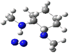
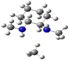
Fig. 1A schematically illustrates the synthesis process of CC3 and RCC3 powders. The CC3 powder was synthesized through nucleophilic addition between 1,3,5-triformaylbenzene and (R,R)-1,2-diaminocyclohexane under the catalysis of TFA, and its spatial structure is depicted in Fig. 1B. After reduction with sodium borohydride, the RCC3 powder was obtained and observed as an octahedral structure with a particle size of approximately 240 nm, as shown in the TEM image in Fig. 1C. The CC3 and RCC3 powders were dissolved in methanol and centrifuged to obtain the supernatant for mass spectrometry detection. As displayed in Fig. 1D, the peaks at 1117.7 m/z in the mass spectrometry detection spectrum of CC3 powder and 1141.9 m/z in that of RCC3 powder corresponded to their molecular weights, respectively,39 indicating the successful synthesis of CC3 and RCC3 powders.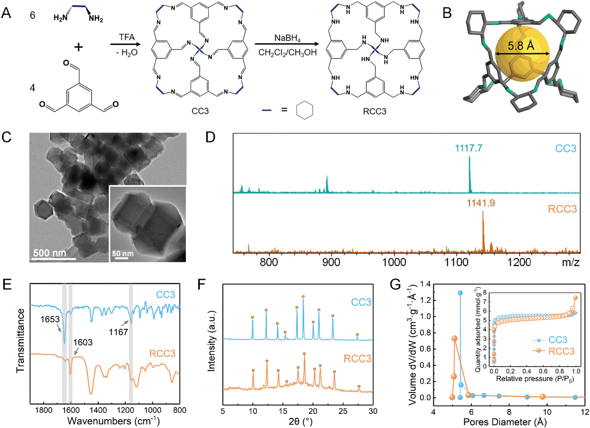 | ||
| Fig. 1 (A) Synthesis process of the CC3 and RCC3 powders. (B) Schematic illustration of the CC3 cage structure. (C) TEM image of the RCC3 powder. (D–G) Mass spectrometry detection spectra, FTIR spectra, PXRD patterns and pore size distributions, and N2 adsorption–desorption curves (inset) at 77 K of the CC3 and RCC3 powders. | ||
Fig. 1E shows the FTIR spectra of the CC3 and RCC3 powders. The characteristic peaks near 1603 cm−1 and 1167 cm−1 were observed in the FTIR spectra of CC3 and RCC3 powders, corresponding to the stretching vibrations of –CC and –C–N groups, respectively.32 Compared with the CC3 powder, the characteristic peak of –CN near 1653 cm−1 was significantly weakened in the spectrum of the RCC3 powder, suggesting a successful reduction of the CC3 powder.
The powder X-ray diffraction (PXRD) pattern of the CC3 powder shown in Fig. 1F was consistent with a previous report.52 Moreover, the peaks in the patterns of the CC3 and RCC3 powders displayed roughly the same locations, indicating a minor change in the crystal structure after the reduction. As shown in Fig. 1G, the CC3 and RCC3 powders exhibited similar N2 adsorption–desorption curves and Brunauer–Emmett–Teller (BET) specific surface areas of 416.2 m2 g−1 and 442.3 m2 g−1, respectively. In addition, the CC3 and RCC3 powders showed similar pore size distribution with an average pore size of around 5.39 Å, suggesting that the cage maintained its pore structure after the reduction.
3.2 Structure and characterization of TPC-RCC3 and TPC-RCC3@PIP films
Fig. 2A illustrates the interfacial reaction between TPC and RCC3 to generate the TPC-RCC3 film. Specifically, TPC acted as a crosslinker to connect the scattered RCC3 organic cages in series to generate a cross-linked topological network. Compared with RCC3 molecules, the TPC-RCC3 film exhibited a slightly larger average pore size of 6.1 Å, as shown in Fig. 2B, suggesting a loose arrangement of RCC3 with the formation of sub-nanochannels.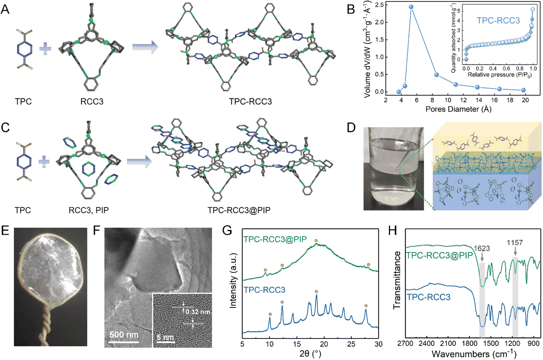 | ||
| Fig. 2 (A) Cross-linking reaction between the TPC and RCC3 molecules. (B) Pore diameter distribution and N2 adsorption–desorption curve at 77 K (inset) of the TPC-RCC3 film. (C) Cross-linking reaction among the TPC, RCC3, and PIP molecules. (D) Fabrication process and schematic structure of the TPC-RCC3@PIP film. (E) Digital picture and (F) high-resolution TEM image of the TPC-RCC3@PIP film generated by the interfacial reaction. (G) PXRD patterns, and (H) FTIR spectra of the TPC-RCC3 and TPC-RCC3@PIP films. | ||
Fig. 2C illustrates the interfacial reaction among TPC, RCC3, and PIP to generate a more compact polyamide structure. Due to the unique cavity structure of RCC3 organic cages, some small guest molecules in the aqueous solution could be encapsulated,53 resulting in the penetration of the polyamide chain into the channel of RCC3 organic cages. Fig. 2D shows the formation process of the TPC-RCC3@PIP film through the cross-linking reaction occurring at the water–hexane phase interface. As shown in Fig. 2E, an intact TPC-RCC3@PIP film could be obtained without any visible defects, suggesting excellent film-forming properties. The high-resolution TEM image of the TPC-RCC3@PIP film shown in Fig. 2F suggested a certain crystalline structure of RCC3 that was retained in the resulting film. The lattice plane spacing in the inset figure is 0.32 nm, corresponding to the diffraction peak of 28.0° in the XRD pattern of the TPC-RCC3@PIP film.
Fig. 2G and S2† display XRD patterns of TPC-PIP, TPC-RCC3, and TPC-RCC3@PIP films. Most of the diffraction peaks of RCC3 were clearly observed in the XRD pattern of the TPC-RCC3 film, indicating that the crystalline structure of RCC3 was retained after reacting with TPC. However, only partial peaks at 9.2°, 12.3°, 18.6°, and 28.0° were found in the XRD pattern of the TPC-RCC3@PIP film. Compared with the TPC-RCC3 film, the weak diffraction peaks of the RCC3 in the XRD pattern of the TPC-RCC3@PIP film were mainly because the polyamide structure generated by the reaction between PIP and TPC increased the proportion of the amorphous phase in the TPC-RCC3@PIP film.
Fig. 2H shows the FTIR spectra of TPC-RCC3 and TPC-RCC3@PIP films. The characteristic peak at 1623 cm−1 corresponded to the stretching vibration of CO in the amide bond, indicating a successful generation of the polyamide structure through the interfacial reaction.54 Compared with the RCC3 powder, the stretching vibration peak of –C–N groups was slightly shifted from 1167 cm−1 to 1157 cm−1 in the spectra of TPC-RCC3 and TPC-RCC3@PIP films, probably due to the formation of additional hydrogen bonds after reacting with TPC, suggesting a tight coupling of RCC3 cages with the adjacent cages or polyamide chains. In addition, the TPC-RCC3@PIP film exhibited favorable thermal stability with decomposition at approximately 280 °C, as shown in Fig. S3.†
3.3 Structure and morphology of the composite membranes
The TPC-RCC3@PIP/mPSf composite membrane was fabricated via the interfacial reaction among TPC, RCC3, and PIP on the mPSf substrate, as depicted in Fig. 3A. Surface elemental analysis of the composite membranes was carried out by XPS spectroscopy. As shown in Fig. 3B, the TPC-RCC3/mPSf and TPC-RCC3@PIP/mPSf composite membranes exhibited similar C 1s compositions, which could be divided into C–C at ∼284.8 eV, C–N at ∼286 eV and N–CO at ∼288.2 eV, demonstrating the successful generation of a polyamide structure on the membrane surface. Notably, the TPC-RCC3@PIP/mPSf composite membrane displayed an obviously higher content of the N–CO peak, mainly due to the participation of PIP during the formation of the polyamide structure.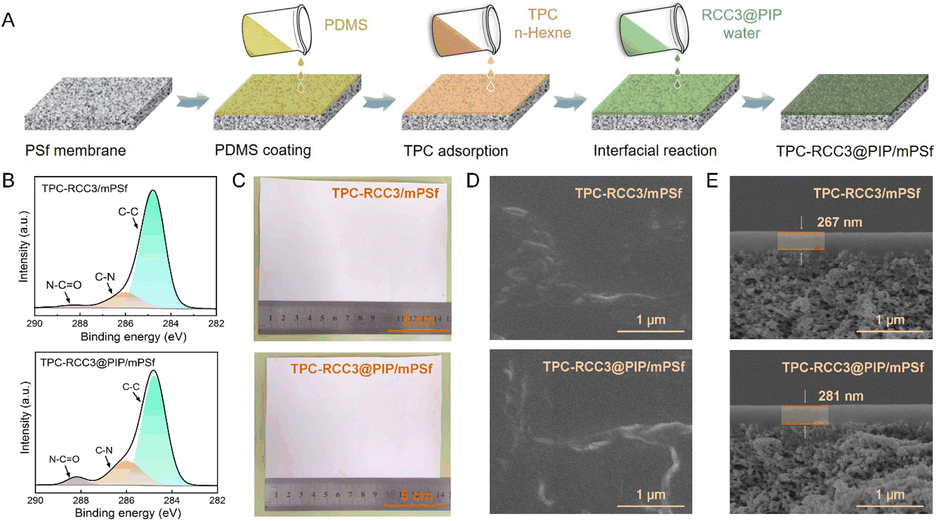 | ||
| Fig. 3 (A) Schematic representation of the fabrication process of the TPC-RCC3@PIP/mPSf composite membrane through the interfacial reaction. (B) C 1s XPS spectra, (C) optical images, (D) surface, and (E) cross-section SEM images of TPC-RCC3/mPSf and TPC-RCC3@PIP/mPSf composite membranes. | ||
In addition, the as-prepared TPC-RCC3/mPSf and TPC-RCC3@PIP/mPSf composite membranes could be easily fabricated with a surface area of more than 100 cm2 without any visible macroscopic defects before and after the gas separation test (Fig. 3C and S1†). The surface and cross-section SEM morphologies of the composite membranes are shown in Fig. 3D and E. After the interfacial reaction, protrusive structures were observed on the membrane surface. The cross-section SEM images showed that the thicknesses of the selective layer were 267 nm and 281 nm for the two composite membranes, respectively, including a PDMS layer of ∼150 nm (Fig. S4†).
3.4 Gas separation performance of the composite membranes
Fig. 4A shows CO2, N2, and CH4 permeances, as well as the CO2/N2 ideal selectivity of TFC membranes fabricated with different aqueous monomers. The TPC-PIP/mPSf composite membrane fabricated with TPC and PIP as the reactive monomers displayed a CO2 permeance of 6080 GPU and an ideal CO2/N2 selectivity of 12.5, which was almost the same as those of the mPSf substrate, indicating a loose polyamide structure generated from the TPC and PIP monomers. The TPC-RCC3/mPSf composite membrane exhibited a CO2 permeance of 5388 GPU and ideal CO2/N2 selectivity of 18.2, while the TPC-RCC3@PIP/mPSf composite membrane showed a CO2 permeance of 3699 GPU and ideal CO2/N2 selectivity of 23.9. Compared with the TPC-PIP/mPSf composite membrane, the composite membranes containing RCC3 showed slightly lower pure gas permeance but much higher CO2/N2 selectivity, indicating that the introduced RCC3 not only enhanced the cross-linking degree to form a denser polyamide structure but also provided exclusive transport channels with abundant amine groups for the preferential penetration of CO2. The single gas adsorption–desorption of the TPC-RCC3@PIP film shown in Fig. S5† also suggested that the TPC-RCC3@PIP film exhibited selective adsorption of CO2 over N2. In addition, N2 and CH4 permeances of the composite membranes decreased substantially after the introduction of RCC3, probably because these two gases permeated through the membrane based on the surface diffusion mechanism.11,55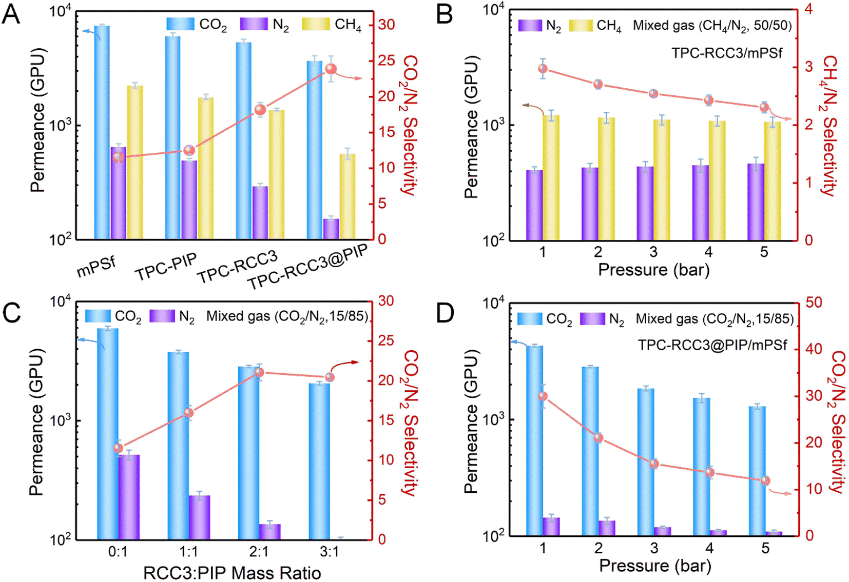 | ||
| Fig. 4 (A) Pure CO2, N2, CH4 permeances, and ideal CO2/N2 selectivity of the mPSf substrate and composite membranes fabricated with various reactive monomers. (B) Mixed CH4/N2 separation performance of the TPC-RCC3/mPSf composite membrane at different feed gas pressures. (C) Mixed CO2/N2 separation performance of the TPC-RCC3@PIP/mPSf (x:1, x = 0, 1, 2, 3) composite membranes at 2 bar. (D) Mixed CO2/N2 separation performance of the TPC-RCC3@PIP/mPSf composite membrane at different feed gas pressures. | ||
Fig. 4B shows the gas separation performance of the TPC-RCC3/mPSf composite membrane with a mixed gas (CH4/N2, 50/50 by volume) under different feed gas pressures. The TPC-RCC3/mPSf composite membrane exhibited a CH4 permeance of 1216 GPU and a CH4/N2 selectivity of 3.0 at 1 bar. The transport of CH4 and N2 through the membrane was largely dependent on their kinetic diameter and condensability,11,55 as shown in Table 1. Although the N2 molecule has a slightly smaller kinetic diameter, the higher critical temperature and polarizability of the CH4 molecule make it have a better condensability and stronger interaction with RCC3 cage molecules.56 Besides, the gas permselectivity of the TPC-RCC3/mPSf composite membrane basically maintained a stable state with increasing the feed gas pressure, having a CH4 permeance of 1069 GPU and CH4/N2 selectivity of 2.3 at 5 bar.
| Gas | Kinetic diameter (Å) | Critical temperature (°C) | Polarizability (×10−25 cm3) | Binding with RCC3 | Binding energy (kJ mol−1) |
|---|---|---|---|---|---|
| CO2 | 3.3 | 31 | 27.6 |
|
43.6 |
| N2 | 3.6 | −147 | 17.6 |
|
7.2 |
| CH4 | 3.8 | −82 | 26.0 |
|
8.0 |
TPC-RCC3@PIP/mPSf (x:1, x = 0, 1, 2, 3) composite membranes were fabricated with a fixed PIP concentration of 0.01 wt% and different RCC3:PIP mass ratios, and the gas separation performance was evaluated with a mixed gas (CO2/N2, 15/85 by volume) at 2 bar. As shown in Fig. 4C, with increasing RCC3:PIP mass ratios, the fabricated TPC-RCC3@PIP/mPSf composite membranes displayed a gradual reduction in CO2 permeance, and an increase in CO2/N2 selectivity. The reduction in gas permeance was mainly attributed to a dense selective layer with the accumulation of RCC3 cages,33 while the increase in gas selectivity further suggested the preferable adsorption and transport for CO2 in the channels provided by RCC3.
Moreover, CO2/N2 separation performance of the TPC-RCC3@PIP/mPSf composite membrane was tested with a mixed gas (CO2/N2, 15/85 by volume) under different feed gas pressures, as displayed in Fig. 4D. The as-prepared TPC-RCC3@PIP/mPSf composite membrane exhibited an excellent CO2 permeance of 4303 GPU and CO2/N2 selectivity of 30 at 1 bar. However, as the feed gas pressure increased, both the CO2 permeance and CO2/N2 selectivity decreased gradually, which was consistent with the typical characteristic of a facilitated transport mechanism.57,58 Meanwhile, the TPC-RCC3@PIP/mPSf composite membrane was also fabricated by a similar procedure with CC3 cages and PIP as the aqueous monomers. As shown in Fig. S6,† the TPC-CC3@PIP/mPSf composite membrane exhibited a CO2 permeance of ∼3332 GPU and CO2/N2 selectivity of ∼7.0 at 1 bar, much lower than those of the TPC-RCC3@PIP/mPSf composite membrane, which was mainly due to the presence of abundant imide bonds in CC3 cages. On one hand, the CC3 cages cannot react with TPC during membrane fabrication, and thus a dispersed and loose structure comprising CC3 cages and polyamide chains generated by the reaction of PIP and TPC was formed in the TPC-CC3@PIP selective layer, leading to its high N2 permeance. On the other hand, the TPC-CC3@PIP selective layer lacked amine groups that reacted reversibly with CO2 molecules, and thus cannot provide channels for CO2 preferential transport, resulting in its low CO2 permeance and CO2/N2 selectivity.
The above results indicated that the TPC-RCC3@PIP/mPSf composite membrane achieved a high gas permeance and an acceptable selectivity for CO2/N2 separation. In addition, the relative errors of gas separation performance of approximately 5% in Fig. 4 suggested a highly repeatable performance of the composite membranes. Nevertheless, the gas selectivity of the TPC-RCC3@PIP/mPSf composite membrane did not reach the desired value, which might result from the short-range ordered RCC3 cage molecules induced by rapid precipitation or crystallization. The research work in Cooper's team indicated that internal cavities and extrinsic porosity might be generated during the synthesis of CC3 cages due to the covalent bonding and rigid shape.45 A rapid precipitation would result in a short-range ordered crystalline structure accompanied by crystal dislocations and grain boundaries.41 Thus, the existing interconnected microporosities, such as intrinsic intracage cavities and extrinsic intercage voids, severely limited the further enhancement of gas selectivity. Similar gas selectivity was also observed in the membrane with CC3 assembled onto an alumina substrate via spin coating.45
3.5 Separation mechanism of the composite membranes
Fig. 5 schematically depicts the CO2, N2, and CH4 transport behavior in gas transport channels generated by TPC, RCC3, and PIP. During the synthesis of the RCC3 cage, the pore structure and connectivity were strongly dictated by the functional groups on cage vertices, thus tending to form an ordered crystalline structure in a window-to-window arrangement. During the cross-linking reaction, the secondary amine groups on the window of RCC3 cages reacted with the chloride groups of TPC molecules, while the cyclohexane groups at the summit of RCC3 cages were not involved in the reaction. Thus, the RCC3 cage could maintain window–window arrangement after the reaction, and gas transport channels were then constructed by the arranged RCC3 cages that were covalently connected with the adjacent cages.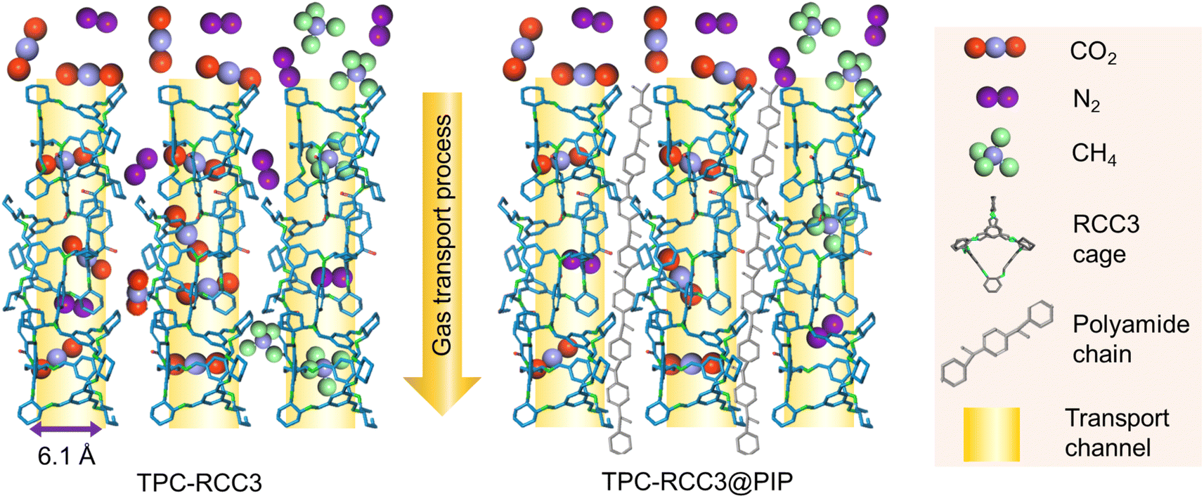 | ||
| Fig. 5 Schematic diagram of CO2, N2, and CH4 transport behaviors in gas transport channels provided by TPC-RCC3 and TPC-RCC3@PIP. | ||
The as-prepared TPC-RCC3 film exhibited an average pore size of 6.1 Å, falling in between the diameter of one CO2 molecule (3.3 Å) and the sum of CO2 and N2 molecules (6.9 Å). In addition, the binding energy between gas molecules and membrane materials has significant effects on the adsorption and transport process of gas molecules. A larger absolute value of binding energy represents a higher adsorption capacity.52 The binding energies between RCC3 molecules and CO2, N2, and CH4 were 43.6 kJ mol−1, 7.2 kJ mol−1 and 8.0 kJ mol−1, respectively, as listed in Table 1. Thus, the amine groups in the RCC3 organic cage allowed CO2 molecules to preferentially adsorb onto the pore channel and transport along the pore wall by monomolecular surface diffusion. Compared with CO2 molecules, the penetration of N2 would be severely hindered by the limited unoccupied pore space, as depicted in Fig. 5.
Although the CO2 transport channel constructed by RCC3 was conducive to CO2/N2 separation, the TPC-RCC3 selective layer was not tight enough to achieve high CO2/N2 selectivity due to the relatively large size and steric hindrance of the cages. After the addition of a trace amount of PIP in the aqueous solution, the PIP could react with TPC to generate linear polyamide chains interspersed with the RCC3 cages to form a denser selective layer. In addition, the TPC-RCC3@PIP film showed excellent CO2/N2 adsorption selectivity at 298 K due to the high density of amine groups in the transport channel (Fig. S5†). Accordingly, the CO2/N2 selectivity of the TPC-RCC3@PIP/mPSf composite membrane experienced a great increase, while its gas permeance exhibited a slight decrease.
3.6 CO2/N2 separation stability and performance comparison with other related membranes
The separation stability of the TPC-RCC3@PIP/mPSf composite membrane was assessed at 2 bar for a 24 h continuous test with dried or humidified mixed CO2/N2 gas, as shown in Fig. 6A. When the feed gas changed from a dry state to a wet state, the CO2 permeance increased by around 20% due to the facilitated transport mechanism in a humidified environment. Once the feed gas recovered to the dry state, the permselectivity basically returned to the original state, suggesting the excellent resilience and long-term stability of the as-prepared composite membrane.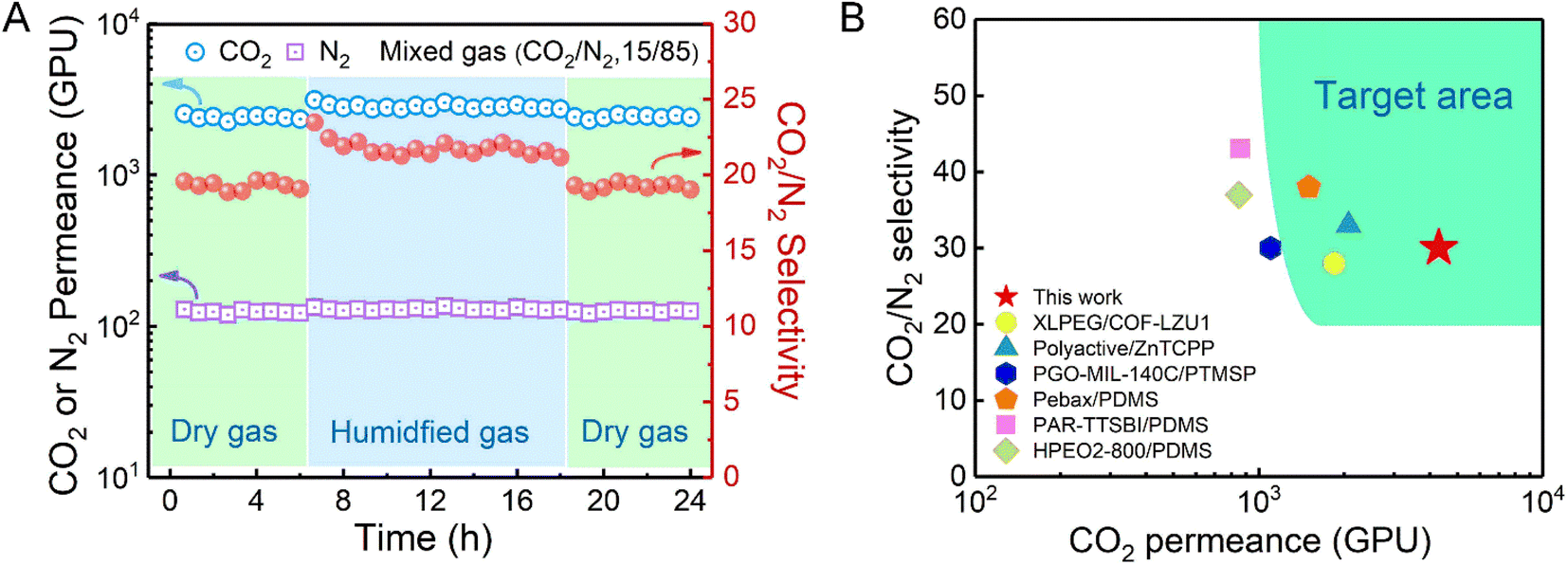 | ||
| Fig. 6 (A) Mixed CO2/N2 separation performance of the TPC-RCC3@PIP/mPSf composite membrane for 24 h at 2 bar. (B) CO2/N2 separation performance of the TPC-RCC3@PIP/mPSf membrane developed in this work in comparison with other reported membranes in terms of the target area for post-combustion CO2 capture. (Detailed data are indicated in Table S1†). | ||
Compared with other related membranes, the TPC-RCC3@PIP/mPSf composite membrane achieved excellent CO2 permeance and acceptable CO2/N2 selectivity (Fig. 6B), which were in the range of the target area proposed by Tim C. Merkel based on power plant post-combustion CO2 capture,21 indicating its potential in industrial CO2 capture from flue gas.
4. Conclusion
In this work, a facile porous organic cage composite membrane for CO2/N2 and CH4/N2 separation was fabricated with reduced CC3 (RCC3) and crosslinkers of PIP and TPC. The RCC3 organic cage provided an amine-rich sub-nanochannel for the rapid penetration of CO2, owing to its narrow aperture of 5.4 Å and a Brunauer–Emmett–Teller specific surface area of 442.3 m2 g−1. The obtained TPC-RCC3/mPSf composite membrane exhibited a high CH4 permeance of 1216 GPU and a CH4/N2 selectivity of 3.0 at 1 bar. The obtained TPC-RCC3@PIP/mPSf composite membrane possessed a high CO2 permeance of 4303 GPU and a CO2/N2 selectivity of 30 at 1 bar and maintained excellent stability under dry or wet feed gas as well as long-term operation. Therefore, owing to its high permselectivity and easy scale-up fabrication of interfacial crosslinking, this novel porous organic cage composite membrane provided a more economical and feasible solution for industrial CO2 capture from flue gas or natural gas purification.Conflicts of interest
There is no conflict to declare.Acknowledgements
This work was supported by the National Key R&D Program of China (No. 2021YFB3802200).References
- M. Ozkan, A.-A. Akhavi, W. C. Coley, R. Shang and Y. Ma, Chem, 2022, 8, 141–173 CAS.
- J. Carnicer, A. Alegria, C. Giannakopoulos, F. Di Giuseppe, A. Karali, N. Koutsias, P. Lionello, M. Parrington and C. Vitolo, Sci. Rep., 2022, 12, 10365 CrossRef CAS PubMed.
- H. Wang, S.-T. B. Lundin, K. Takanabe and S. T. Oyama, J. Mater. Chem. A, 2022, 10, 12869–12881 RSC.
- J. W. Yoon, H. Chang, S. J. Lee, Y. K. Hwang, D. Y. Hong, S. K. Lee, J. S. Lee, S. Jang, T. U. Yoon, K. Kwac, Y. Jung, R. S. Pillai, F. Faucher, A. Vimont, M. Daturi, G. Ferey, C. Serre, G. Maurin, Y. S. Bae and J. S. Chang, Nat. Mater., 2017, 16, 526–531 CrossRef CAS PubMed.
- D. Ren, Z. Li and H. Ding, IOP Conf. Ser.: Earth Environ. Sci., 2021, 657 Search PubMed.
- N. N. R. Ahmad, C. P. Leo and A. W. Mohammad, Mater. Lett., 2021, 304 Search PubMed.
- S. S. Yoon, H. K. Lee and S. R. Hong, Membranes, 2021, 11 Search PubMed.
- G. Li, W. Kujawski, K. Knozowska and J. Kujawa, Membranes, 2021, 11 CAS.
- S. V. Shaligram and S. L. Regen, Chem. Commun., 2022, 58, 3557–3560 RSC.
- Y. Wang, L. Li, X. Zhang, J. Li, J. Wang and N. Li, J. Membr. Sci., 2020, 599 Search PubMed.
- Y. Zhou, Y. Yuan, S. Cong, X. Liu and Z. Wang, Sep. Purif. Technol., 2022, 300 Search PubMed.
- B. Zhu, S. He, Y. Wu, S. Li and L. Shao, Engineering, 2022 DOI:10.1016/j.eng.2022.03.016.
- M. Liu, M. D. Nothling, P. A. Webley, Q. Fu and G. G. Qiao, Acc. Chem. Res., 2019, 52, 1905–1914 CrossRef CAS PubMed.
- M. Liu, M. D. Nothling, S. Zhang, Q. Fu and G. G. Qiao, Prog. Poly. Sci., 2022, 126 Search PubMed.
- Z. Ali, Y. Wang, W. Ogieglo, F. Pacheco, H. Vovusha, Y. Han and I. Pinnau, J. Membr. Sci., 2021, 618 Search PubMed.
- C. Jiao, X. Song, X. Zhang, L. Sun and H. Jiang, ACS Appl. Mater. Interfaces, 2021, 13, 18380–18388 CrossRef CAS PubMed.
- X. Xu, J. Dong, X. Xiao, X. Zhao and Q. Zhang, ACS Sustainable Chem. Eng., 2021, 9, 5546–5556 CrossRef CAS.
- N. Li, Z. Wang and J. Wang, J. Membr. Sci., 2022, 642 Search PubMed.
- L. Z. Qin, X. H. Xiong, S. H. Wang, L. L. Meng, T. A. Yan, J. Chen, N. X. Zhu, D. H. Liu and Z. W. Wei, Inorg. Chem., 2021, 60, 17440–17444 CrossRef CAS PubMed.
- B. Wang, J. Xu, J. Wang, S. Zhao, X. Liu and Z. Wang, J. Membr. Sci., 2021, 625 Search PubMed.
- T. C. Merkel, H. Lin, X. Wei and R. Baker, J. Membr. Sci., 2010, 359, 126–139 CrossRef CAS.
- H. Xu, W. Feng, M. Sheng, Y. Yuan, B. Wang, J. Wang and Z. Wang, Chin. J. Chem. Eng., 2022, 43, 152–160 CrossRef.
- Y. Yuan, Z. Qiao, J. Xu, J. Wang, S. Zhao, X. Cao, Z. Wang and M. D. Guiver, J. Membr. Sci., 2021, 620 CrossRef PubMed.
- N. Zhang, A. Ishag, Y. Li, H. Wang, H. Guo, P. Mei, Q. Meng and Y. Sun, J. Cleaner Prod., 2020, 277 CAS.
- Y. Zhang, J. Guo, G. Han, Y. Bai, Q. Ge, J. Ma, C. H. Lau and L. Shao, Sci. Adv., 2021, 7, eabe8706 CrossRef CAS PubMed.
- M. R. Abdul Hamid, Y. Qian, R. Wei, Z. Li, Y. Pan, Z. Lai and H.-K. Jeong, J. Membr. Sci., 2021, 640 Search PubMed.
- J.-Y. Lai, T.-Y. Wang, C. Zou, J.-J. Chen, L.-C. Lin and D.-Y. Kang, J. Membr. Sci., 2022, 661 Search PubMed.
- Y. Ying, Z. Zhang, S. B. Peh, A. Karmakar, Y. Cheng, J. Zhang, L. Xi, C. Boothroyd, Y. M. Lam, C. Zhong and D. Zhao, Angew. Chem., Int. Ed. Engl., 2021, 60, 11318–11325 CrossRef CAS PubMed.
- S. He, B. Zhu, X. Jiang, G. Han, S. Li, C. H. Lau, Y. Wu, Y. Zhang and L. Shao, Proc. Natl. Acad. Sci. U. S. A., 2022, 119 Search PubMed.
- J. Guan, T. Huang, W. Liu, F. Feng, S. Japip, J. Li, J. Wu, X. Wang and S. Zhang, Cell Rep. Phys. Sci., 2022, 3, 100864 CrossRef CAS.
- T. Tozawa, J. T. A. Jones, S. I. Swamy, S. Jiang, D. J. Adams, S. Shakespeare, R. Clowes, D. Bradshaw, T. Hasell and A. I. Cooper, Nat. Mater., 2009, 8, 973–978 CrossRef CAS PubMed.
- T. Xu, B. Wu, L. Hou, Y. Zhu, F. Sheng, Z. Zhao, Y. Dong, J. Liu, B. Ye, X. Li, L. Ge, H. Wang and T. Xu, J. Am. Chem. Soc., 2022, 144, 10220–10229 CrossRef CAS PubMed.
- Y. Wang, Y. Yang, Z. Zha, J. Wang, Z. Wang and S. Zhao, J. Membr. Sci., 2022, 659 CAS.
- K. Tian, S. M. Elbert, X. Y. Hu, T. Kirschbaum, W. S. Zhang, F. Rominger, R. R. Schroder and M. Mastalerz, Adv. Mater., 2022, 34, e2202290 CrossRef PubMed.
- J. M. Lucero and M. A. Carreon, ACS Appl. Mater. Interfaces, 2020, 12, 32182–32188 CrossRef CAS PubMed.
- Q. Zhang, H. Li, S. Chen, J. Duan and W. Jin, J. Membr. Sci., 2020, 611 Search PubMed.
- T. Hasell, M. Miklitz, A. Stephenson, M. A. Little, S. Y. Chong, R. Clowes, L. Chen, D. Holden, G. A. Tribello, K. E. Jelfs and A. I. Cooper, J. Am. Chem. Soc., 2016, 138, 1653–1659 CrossRef CAS PubMed.
- A. He, Z. Jiang, Y. Wu, H. Hussain, J. Rawle, M. E. Briggs, M. A. Little, A. G. Livingston and A. I. Cooper, Nat. Mater., 2022, 21, 463–470 CrossRef CAS PubMed.
- X. Yang, J.-K. Sun, M. Kitta, H. Pang and Q. Xu, Nat. Catal., 2018, 1, 214–220 CrossRef CAS.
- H. Liu, X. Duan, Y.-K. Lv, L. Zhu, Z. Zhang, B. Yu, Y. Jin, Y. Si, Z. Wang, B. Li and P. Peng, Chem. Eng. J., 2021, 426 Search PubMed.
- T. Hasell, J. L. Culshaw, S. Y. Chong, M. Schmidtmann, M. A. Little, K. E. Jelfs, E. O. Pyzer-Knapp, H. Shepherd, D. J. Adams, G. M. Day and A. I. Cooper, J. Am. Chem. Soc., 2014, 136, 1438–1448 CrossRef CAS PubMed.
- Z. Qiao, M. Sheng, J. Wang, S. Zhao and Z. Wang, AIChE J., 2019, 65, 239–249 CrossRef CAS.
- B. Wang, Z. Qiao, J. Xu, J. Wang, X. Liu, S. Zhao, Z. Wang and M. D. Guiver, Adv. Mater., 2020, 32, e1907701 CrossRef PubMed.
- K. Krishnan, J. M. Crawford, P. K. Thallapally and M. A. Carreon, Ind. Eng. Chem. Res., 2022, 61, 10547–10553 CrossRef CAS.
- Q. Song, S. Jiang, T. Hasell, M. Liu, S. Sun, A. K. Cheetham, E. Sivaniah and A. I. Cooper, Adv. Mater., 2016, 28, 2629–2637 CrossRef CAS PubMed.
- K. Qu, J. Xu, L. Dai, Y. Wang, H. Cao, D. Zhang, Y. Wu, W. Xu, K. Huang, C. Lian, X. Guo, W. Jin and Z. Xu, Angew. Chem., Int. Ed. Engl., 2022, 61, e202205481 CAS.
- M. E. Briggs and A. I. Cooper, Chem. Mater., 2017, 29, 149–157 CrossRef CAS PubMed.
- M. Liu, M. A. Little, K. E. Jelfs, J. T. Jones, M. Schmidtmann, S. Y. Chong, T. Hasell and A. I. Cooper, J. Am. Chem. Soc., 2014, 136, 7583–7586 CrossRef CAS PubMed.
- P. Li, Z. Wang, W. Li, Y. Liu, J. Wang and S. Wang, ACS Appl. Mater. Interfaces, 2015, 7, 15481–15493 CrossRef CAS PubMed.
- Y. Gao, Z. Qiao, S. Zhao, Z. Wang and J. Wang, J. Mater. Chem. A, 2018, 6, 3151–3161 RSC.
- L. Goerigk and S. Grimme, Phys. Chem. Chem. Phys., 2011, 13, 6670–6688 RSC.
- E. Martinez-Ahumada, D. He, V. Berryman, A. Lopez-Olvera, M. Hernandez, V. Jancik, V. Martis, M. A. Vera, E. Lima, D. J. Parker, A. I. Cooper, I. A. Ibarra and M. Liu, Angew. Chem., Int. Ed. Engl., 2021, 60, 17556–17563 CrossRef CAS PubMed.
- H. Wang, Y. Jin, N. Sun, W. Zhang and J. Jiang, Chem. Soc. Rev., 2021, 50, 8874–8886 RSC.
- Z. Zhang, X. Shi, R. Wang, A. Xiao and Y. Wang, Chem. Sci., 2019, 10, 9077–9083 RSC.
- K. A. Lokhandwala, I. Pinnau, Z. He, K. D. Amo, A. R. DaCosta, J. G. Wijmans and R. W. Baker, J. Membr. Sci., 2010, 346, 270–279 CrossRef CAS.
- D. F. Sanders, Z. P. Smith, R. Guo, L. M. Robeson, J. E. McGrath, D. R. Paul and B. D. Freeman, Polymer, 2013, 54, 4729–4761 CrossRef CAS.
- S. Nithin Mithra and S. S. Ahankari, Mater. Today Sustain., 2022, 19, 100191 CrossRef.
- M. E. Kojabad, A. Babaluo, A. Tavakoli and H. G. Kahnamouei, Process Saf. Environ. Prot., 2021, 156, 304–314 CrossRef CAS.
Footnote |
| † Electronic supplementary information (ESI) available. See DOI: https://doi.org/10.1039/d2ta09632c |
| This journal is © The Royal Society of Chemistry 2023 |