 Open Access Article
A double-redox aqueous capacitor with high energy output†
Adam
Slesinski
 *a,
Sylwia
Sroka
 a,
Sergio
Aina
 b,
Justyna
Piwek
 a,
Krzysztof
Fic
 a,
M. Pilar
Lobera
 bc,
Maria
Bernechea
 bcd and
Elzbieta
Frackowiak
 *a
*a
aInstitute of Chemistry and Technical Electrochemistry, Poznan University of Technology, 60-965 Poznan, Poland
bDepartment of Chemical and Environmental Engineering, Instituto de Nanociencia y Materiales de Aragón (INMA) CSIC-Universidad de Zaragoza, University of Zaragoza, Campus Río Ebro-Edificio I+D, C/ Mariano Esquillor S/N, 50018 Zaragoza, Spain
cCentro de Investigación Biomédica en Red de Bioingeniería, Biomateriales y Nanomedicina, Instituto de Salud Carlos III, 50018, Zaragoza, Spain
dARAID, Government of Aragon, 50018, Zaragoza, Spain
First published on 28th February 2023
Abstract
The paper puts forward the concept of a double-redox electrochemical capacitor operating in an aqueous electrolyte. The redox activity of sulphur from insoluble Bi2S3 nanocrystals embedded in the negative electrode material (up to 10 wt%) operating in 1 mol L−1 Li2SO4 electrolyte is demonstrated. It is also shown that the performance is significantly boosted using MPA (3-mercaptopropionic acid) as a ligand attached to the surface of the nanocrystals, which allows for more efficient use of Bi2S3 redox active species. This redox activity is combined with the reactions of iodides, which occur at the opposite electrode with 1 mol L−1 NaI. This enables the formation of a discharge voltage plateau that effectively boosts the capacitance (275 F g−1), and thus specific energy of the device owing to the relatively high cell voltage of 1.5 V. This performance is possible due to the advantageous electrode mass ratio (m−![[thin space (1/6-em)]](https://www.rsc.org/images/entities/char_2009.gif) :
:![[thin space (1/6-em)]](https://www.rsc.org/images/entities/char_2009.gif) m+ = 2
m+ = 2![[thin space (1/6-em)]](https://www.rsc.org/images/entities/char_2009.gif) :
:![[thin space (1/6-em)]](https://www.rsc.org/images/entities/char_2009.gif) 1), which helps to balance the charge. The rate capability test of the device demonstrates its capacitance retention of 73% at 10 A g−1 of the discharge current. The different states of the redox species ensure their operation at separate electrodes in an immiscible manner without a shuttling effect. The specific interactions of the redox active species with carbon electrodes are supported by operando Raman spectroscopy.
1), which helps to balance the charge. The rate capability test of the device demonstrates its capacitance retention of 73% at 10 A g−1 of the discharge current. The different states of the redox species ensure their operation at separate electrodes in an immiscible manner without a shuttling effect. The specific interactions of the redox active species with carbon electrodes are supported by operando Raman spectroscopy.
1. Introduction
The annual world energy consumption is increasing constantly, particularly in the last few years. Fossil fuels still stand out with more than 80% of the global energy consumption.1 Nowadays, the whole of Europe must face an energy crisis and the risk of blackouts. Natural gas prices have surged almost 600%, and as a consequence, the benchmark electricity prices increased almost 3 times in 2022. Therefore, it is of high importance to fill the gap between energy generation and demand, and as a result, to develop novel, inexpensive energy storage/conversion systems with reliable performance. Among them, electrochemical capacitors (ECs) are well-suited for such applications ensuring high peak currents with a moderate specific energy.2,3The electrochemical capacitor was constructed using two well-developed surface area carbon electrodes separated by a permeable separator and immersed in an electrolytic solution. Its operation mode is based on the adsorption/desorption of reversible ions during charging/discharging processes forming an electric double layer (EDL) at the electrode/electrolyte interface.4,5 The energy output of ECs is proportional to the capacitance and square of the operating voltage according to the formula E = 0.5C·U2, where C – capacitance, U – voltage. Currently, two main strategies are used to increase the energy of ECs. One includes the operating voltage increase by the development of new organic medium electrolytes. The second option relies on capacitance enhancement and the introduction of redox-active species to the capacitor system, thus bringing them closer to batteries. This work is focused on the second case, where two redox couples are involved.
Most commonly used electrolytes for commercial capacitors contain organic electrolytes such as 1 mol L−1 of tetraethylammonium tetrafluoroborate (TEABF4) salt dissolved in acetonitrile (AN) or propylene carbonate (PC) solvent. Both electrolytes ensure a high operational voltage window (2.5–2.8 V).6,7 Moreover, acetonitrile is characterized by high electrochemical stability and relatively high conductivity even at low temperatures (down to −40 °C). However, it should be mentioned that its high flammability raises safety problems for the final device. PC solvent seems to solve the safety issue, however, at the expense of lower conductivity, particularly at low temperatures.8
In contrast, water medium has become more widely explored in the last few years.9–11 It is characterized by much higher conductivity values than organic electrolytes (ca. 0.02 S cm−1 for TEABF4, while from ca. 50 mS cm−1 for neutral salts to ca. 1 S cm−1 for 30% H2SO4)2 which is directly reflected by higher power values of aqueous medium ECs. Moreover, capacitor components for water medium do not require a drying process, and oxygen and the water-free atmosphere is adequate for the system assembly.12 One of the main disadvantages of water-based electrolytes is the low voltage window (ca. 1.23 V) due to the thermodynamic stability of water.13 KOH and H2SO4 practically operate up to 1 V; however, neutral electrolytes can easily reach 1.5–1.8 V.5,14
Nowadays, redox-active species are introduced to the system to improve the energy output of the electrochemical capacitors.15 Depending on the redox pair selection, the positive or/and negative electrode of the cell is enhanced, revealing battery-like behaviour. One may consider different electrolytic species such as bromides, hydroxyquinones, iodides, selenocyanates, or thiocyanates.11,16–18 It has been shown that iodide/iodine species are perfect candidates for a stable electrolyte with good conductivity, improving the capacitance ca. 2–3-fold.19–24 Iodide species operate at the positive side of ECs according to the following reactions:
| 2I− ↔ I2 + 2e− | (1) |
| 3I− ↔ I3− + 2e− | (2) |
Until now, there were many attempts to boost electrochemical capacitors via redox active species addition. Such a device, possessing battery-like characteristics, was presented recently, where two conjugated redox pairs were used in separate EC compartments. 1 mol L−1 KI solution was used at the positive electrode of EC, while 1 mol L−1 VOSO4 was at the negative one. One should mention that the system suffered from capacitance fade over time, due to the cross-mixing of two electrolytes. To solve this issue, a Nafion cation exchange membrane was used, ensuring the stability of 5000 cycles.24 However, it is worth highlighting that the use of Nafion membrane is not a cost-effective solution for capacitors. Therefore, the approach presented in this paper overcomes the previously observed cross-mixing issue. One redox species (sulphur) in the form of nanocrystals is embedded in the electrode material, while the second one is placed in the electrolytic solution (iodide).
Over the years, colloidal semiconductor nanocrystals (NCs) have been explored in electrochemical applications due to their promising properties. More precisely, bismuth sulphide (Bi2S3) NCs have received some attention due to their abundance, affordability, redox activity, and non-toxic characteristics. Among various properties of Bi2S3 nanocrystals, including semiconductive ones, its nature allows for excellent redox activity. This can be successfully utilised in electrochemical capacitors (as an additive to the electrode material) to increase capacitance and subsequently specific energy. As an example, in previous works, transition metal sulphide NCs have been combined with carbon-based materials such as graphene,25 reduced graphene oxide (rGO)26–28 and poly(3,4-ethylenedioxypyrrole) (PEDOP)29 to synthesise functional materials to enhance properties. Materials for supercapacitors yielded promising capacitance values of 400 F g−1, 396 F g−1, and 329 F g−1, respectively, however, the voltage range was not examined.
In this work, nanorod-shaped Bi2S3 NCs have been synthesized following a fast, low-cost, hot-injection method to functionalise commercial high-surface-area carbon, YP50F, to prepare electrode materials for supercapacitors. Additionally, due to the high hydrophobicity nature of the oleic acid chains attached to the NCs during the preparation step, a ligand-exchange post-treatment with 3-mercaptopropionic acid (MPA) has been explored trying to enhance the wettability and electrochemical performance of the NCs.30 As it will be presented, the redox activity of the NCs can be enhanced with this treatment when used in a neutral aqueous electrolyte.
In order to boost the overall performance of the final device and balance the charge at the negative electrode originating from the presence of sulphide, iodide/iodine species were applied at the positive electrode of the final device. This combination enables a high specific energy EC to be obtained. Namely, the specific energy of this environmentally friendly device with aqueous electrolyte approaches the capacitor operating in the organic electrolyte at 2.7 V. Similar investigations where the capacitance was boosted via two redox contributions from both electrode and electrolyte were found in the work of J. Y. Hwang et al., however, it was presented for microcapacitors.31 Our paper extends the consideration of aqueous medium electrochemical capacitors enhanced with redox active species embedded both in the electrode and electrolyte material. The balancing effects can be also achieved by mass asymmetrisation of the electrodes. It was shown that this operation can optimise and enhance the performance and cycle life of the capacitor by increasing the utilisation rate of the electrodes.32 The effect of different ion radii with respect to electrode mass balance in double-layer capacitors was investigated by B. Anders et al.33 Redox-enhanced capacitors of methyl viologen (MV)/bromide electrolyte with a high specific energy of ∼14![[thin space (1/6-em)]](https://www.rsc.org/images/entities/char_2009.gif) W h kg−1 were presented in 2015, but both redox pairs are in the electrolyte.18 Dual-redox electrochemical capacitors were also introduced in the work of B. Evanko et al., where the reactions involved solid complexation, however, the device resembles a battery more than a supercapacitor and the final rate capability slowed down.34 The described approaches differ from the hybrid device presented in this work, where both electrodes operated based on different charge storage mechanisms.
W h kg−1 were presented in 2015, but both redox pairs are in the electrolyte.18 Dual-redox electrochemical capacitors were also introduced in the work of B. Evanko et al., where the reactions involved solid complexation, however, the device resembles a battery more than a supercapacitor and the final rate capability slowed down.34 The described approaches differ from the hybrid device presented in this work, where both electrodes operated based on different charge storage mechanisms.
Here, Bi2S3 nanocrystals were used to boost the negative electrode and overall performance of the device, still retaining capacitive properties, whereas, iodides provide a high capacity of the positive electrode.35 Sulphides that are readily studied as electrodes in supercapacitors are transition metal sulphides, to which Bi2S3 does not belong. The reason is that it does not form multiple stable forms; therefore, it is not popular in this field. However, it can be found in photocatalysis due to its attractive band gap and tunability. Investigating its behaviour in capacitors, it is believed to provide the development of multipurpose devices (e.g. photocapacitor). There are several studies on Bi2S3 electrochemistry in energy storage devices carried out by other research groups. For example, K. Ghosh et al. indicated barely recognizable activity of Bi2S3 in the Bi2S3/rGO capacitor.36 They assigned it to the possible reversible reaction of Bi2S3 + OH− ⇆ Bi2S3OH + e− following other work by G. Nie et al. where a redox reaction is more visible.27 This reaction is also indicated by A. Moyseowicz et al.37 However, in each case, no proof or explanation of this reaction was given.
2. Experimental
2.1 Chemicals
Bismuth acetate (99.999% metal basis) precursor was provided by Alfa Aesar, hexamethyldisilathiane (HMS), 1-octadecene (90%), oleic acid, 3-mercaptopropionic acid (MPA), Li2SO4 and NaI by Sigma-Aldrich, methanol (≥99.9%) acetonitrile (≥99.9%) and toluene (≥99.3%) by VWR Chemicals and sulfuric acid (96%) by ACROS Organics.2.2 Bi2S3 NCs synthesis
Semiconductor colloidal Bi2S3 nanorods (14 × 19 nm) were synthesised following the reported hot-injection method by M. Bernechea et al.38 using bismuth acetate and hexamethyldisilathiane as precursors. Oleic acid was used as a solvent and capping agent for the nanocrystals. The bismuth sulphide nanocrystals were finally dispersed in toluene.2.3 Hybrid preparation
Carbon + NCs hybrids (5 and 10% w/w) were prepared by mixing carbon powder with adequate volumes of Bi2S3 nanocrystals (NCs) solution (1.4 g L−1 in toluene) for 20 minutes under vigorous stirring. Afterwards, the hybrids were washed several times with toluene and dried at 100 °C. For the 3-mercaptopropionic acid (MPA) treatments, the carbon + NCs hybrids were mixed with a 1 mol L−1 MPA, 0.1 mol L−1 H2SO4 solution in acetonitrile for 30 minutes. The samples were washed with acetonitrile and toluene and then dried at 100 °C.2.4 Characterisation of hybrids
Thermogravimetric analysis (TGA) was performed at 35 °C to 1000 °C at a heating rate of 10 °C min−1 under 50 mL min−1 air flow on a METTLER Toledo instrument. Powder X-ray diffraction (XRD) was performed on a PANalytical Empyrean instrument in Bragg–Brentano configuration using Cu Kα radiation and equipped with a PIXcel1D detector. X-ray photoelectron spectroscopy (XPS) was performed with an Axis Supra spectrometer (Kratos Tech). The spectra were excited by a monochromatic Al Kα source at 1486.6 eV. Analysis of the spectra was performed using CasaXPS software and the binding energies were referenced to the internal C 1s standard at 284.6 eV. Transmission electron microscopy (TEM) images were taken using a Tecnai F30 microscope and the samples were prepared by sonicating the powders in ethanol and adding a couple of drops on holey-carbon copper grids. Scanning electron microscopy (SEM) images and energy-dispersive X-ray spectroscopy (EDX) analysis were performed using an SEM Inspect 50 instrument. FTIR measurements were performed using the Vertex-70 FTIR spectrophotometer (Bruker). Data points were collected at a resolution of 4 cm−1 and with 512 scans. The surface area of the material was determined using BET theory based on the nitrogen adsorption/desorption data at 77 K (ASAP 2460, Micromeritics).2.5 Electrochemical capacitor assembly and characterisation
The measurements were performed in a Swagelok cell with stainless steel (316L) current collectors protected with conductive glue. To monitor the potential changes of each electrode separately, reference electrode Hg|Hg2SO4 in 0.5 mol L−1 K2SO4 (E0 = 0.64 V vs. SHE) was added to the two-electrode capacitor setup. The voltammograms of single electrodes were acquired in such a three-electrode configuration. Kuraray YP50F carbon was used as the electrode material. Carbon electrodes were prepared as self-standing films with PTFE binder and C65 soot as a conductive agent (YP50F-90%, PTFE – 5%, C65 – 5%). This work includes utilization of both the carbon material and mass loading asymmetry in the capacitor electrodes. The specific configuration in the experiments throughout the text is given within appropriate paragraphs. 1 mol L−1 Li2SO4 or NaI solutions were used as the electrolyte. Whatman glass fiber GF/A (φ = 12 mm) was the separator in all systems. The electrochemical measurements were performed on a multichannel VMP3 galvanostat/potentiostat from Bio-Logic, France. The capacitance values were presented per average mass of both electrodes.2.6 Operando measurements
Operando Raman spectroscopy analysis was carried out on a microporous YP50F carbon electrode (positive electrode) and modified YP50F + 5 wt% Bi2S3 + MPA electrode (negative electrode) operating in an aqueous 1 mol L−1 NaI electrolyte. Raman spectra were taken during the electrochemical operation in a specially designed cell consisting of a sapphire window that permitted the incident laser to be focused onto the studied electrode as it was running with a current collector and a plastic body with a seal and screw cap. Raman spectra were recorded with a ThermoFisher DXR Raman microscope equipped with a 532 nm laser from the electrode's rear side. The electrochemical measurement for this experiment consisted of cyclic voltammetry (CV) from 0–1.5 V at a scan rate of 2 mV s−1, with Raman spectra collection every 30 mV. A scan rate of 2 mV s−1 was selected due to its sensitivity to any side reactions, and to ensure a high resolution of the obtained Raman Spectra.2.7 Step potential electrochemical spectroscopy (SPECS) measurements
For the measurements, YP50F + 5 wt% Bi2S3 + MPA was used as a negative electrode and YP50F as a positive electrode with a 2![[thin space (1/6-em)]](https://www.rsc.org/images/entities/char_2009.gif) :
:![[thin space (1/6-em)]](https://www.rsc.org/images/entities/char_2009.gif) 1 mass ratio, respectively, in 1 mol L−1 NaI (System B). For the sake of comparison, another two systems were assembled, where YP50F was used as both the negative and positive electrode (System A), and YP50F + 5 wt% Bi2S3 without MPA (System C) with the same conditions as before (mass ratio, electrolyte). The potential range of both electrodes was first determined in a 2-electrode Swagelok cell with RE using galvanostatic charge/discharge (1 A g−1) for each separate system. The further procedure involved 3 cycles of CV (1 mV s−1) in a predetermined potential for each electrode in a 3-electrode system, followed by step potential electrochemical spectroscopy (SPECS) measurements where equal magnitude potential steps of 10 mV controlled by chronoamperometry (CA) and 10 s rest time were applied. To calculate the total current (IT), the following eqn (3) was applied:
1 mass ratio, respectively, in 1 mol L−1 NaI (System B). For the sake of comparison, another two systems were assembled, where YP50F was used as both the negative and positive electrode (System A), and YP50F + 5 wt% Bi2S3 without MPA (System C) with the same conditions as before (mass ratio, electrolyte). The potential range of both electrodes was first determined in a 2-electrode Swagelok cell with RE using galvanostatic charge/discharge (1 A g−1) for each separate system. The further procedure involved 3 cycles of CV (1 mV s−1) in a predetermined potential for each electrode in a 3-electrode system, followed by step potential electrochemical spectroscopy (SPECS) measurements where equal magnitude potential steps of 10 mV controlled by chronoamperometry (CA) and 10 s rest time were applied. To calculate the total current (IT), the following eqn (3) was applied: | (3) |
3. Results and discussion
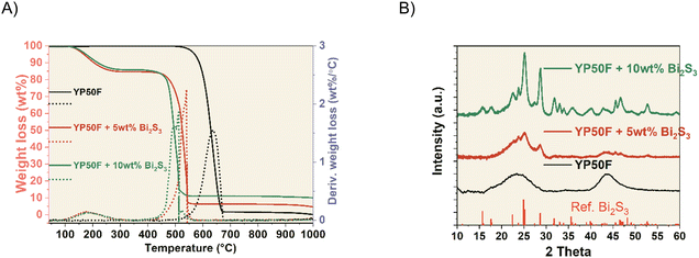
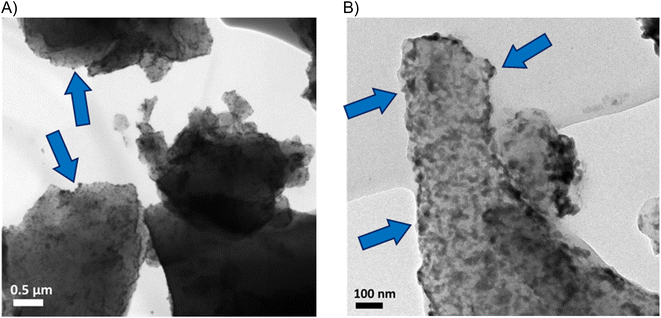
YP50F + NCs hybrids were prepared by mixing carbon with the solution of nanocrystals (NCs). YP50F + 5 wt% Bi2S3 and YP50F + 10 wt% Bi2S3 hybrids were characterized to confirm the control over the NCs loading. TGA analysis showed a first mass loss starting at 110 °C corresponding to the remaining solvent that could not be removed after the drying. Between 450 °C and 650 °C, a great mass loss, attributed to burning processes, was observed. Finally, the remaining constant weight directly correlated with the nominal amount of the loaded NCs. The YP50F + 5 wt% Bi2S3 sample showed a remaining constant weight of 4.5% and the YP50F + 10 wt% Bi2S3 sample showed 9.5 wt% (Fig. 1A). This indicated the successful loading procedure of NCs. XRD patterns of carbonaceous hybrids (Fig. 1B) showed peaks corresponding to Bi2S3 NCs with the amorphous (002) and (101/100) carbon peaks. In the YP50F + 10 wt% Bi2S3 sample, the NCs peaks were more prominent while the carbon ones became more discrete. This suggested the successful incorporation of NCs on the carbon material and significant differences in the intensity of the peaks between 5 wt% and 10 wt% hybrids. It is possible that in the case of 5 wt% content, the NCs reflections were damped by the amorphous carbon, while their bigger loading (10 wt%) enabled them to extend more from the bulk. Their electrochemical availability can be therefore higher.These results agree with TEM and SEM imaging, and semi-quantitative EDX analysis. TEM (Fig. 2 and S1†) and SEM (Fig. S2†) images show a homogeneous distribution of Bi2S3 NCs on the surface of the carbon. On the SEM backscattered electron diffraction mode (BSED), bright dots are attributed to heavier elements, i.e., bismuth atoms from NCs. EDX analysis indicates 5.1 wt% Bi and 10.6 wt% Bi for 5 wt% and 10 wt% hybrids, respectively (Table 1).
| C (wt%) | O (wt%) | Bi (wt%) | S (wt%) | |
|---|---|---|---|---|
| YP50F | 97.7 | 2.3 | — | — |
| YP50F + 5 wt% Bi2S3 | 89.2 | 4.8 | 5.1 | 1.0 |
| YP50F + 5 wt% Bi2S3 + MPA | 85.9 | 5.9 | 4.8 | 3.3 |
| YP50F + 10 wt% Bi2S3 | 83.6 | 3.7 | 10.6 | 2.1 |
| YP50F + 10 wt% Bi2S3+ MPA | 80.5 | 5.2 | 10.0 | 4.3 |
XPS analysis were performed to understand the interaction between Bi2S3 NCs and the carbon substrate. In the Bi 4f region of Bi2S3 NCs, two components were detected. The component at lower binding energy (157.9 eV) is attributed to Bi–S bonds and the second component (158.9 eV) to Bi–O bonds, probably coming from partially oxidized Bi–S species and Bi–O bonding of the NCs to the oleic acid ligands.38,39 The peaks appearing at 160.7 and 161.9 eV correspond to the S 2p region. The ratio between Bi–O/Bi–S in the NCs was 0.65. The deconvolution of the hybrids Bi 4f region shows the same 2 components with a more intense Bi–O curve. The Bi–O/Bi–S ratio is 3.2 and 2.2 for 5 wt% and 10 wt% hybrids, respectively (Fig. 3). This points to the formation of new Bi–O bonds, suggesting the bonding between the bismuth in the NCs and the oxygen-containing groups on the surface of YP50F carbon.39
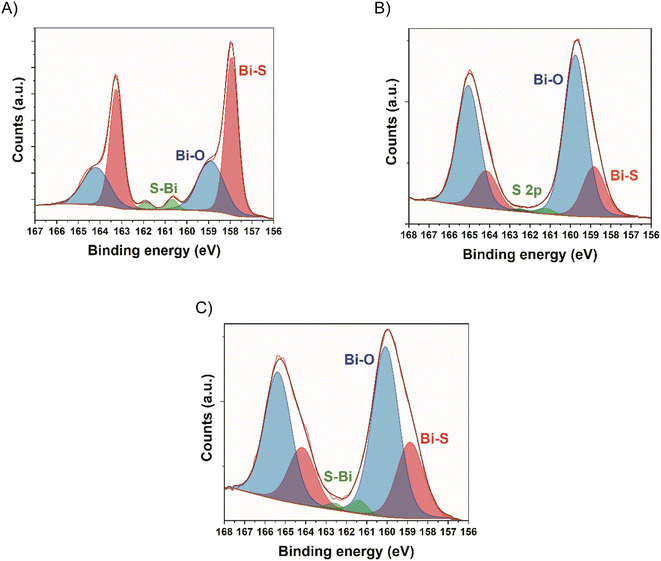 | ||
| Fig. 3 High resolution Bi 4f core spectrum of (A) Bi2S3 NCs, (B) YP50F + 5 wt% Bi2S3 hybrid, (C) YP50F + 10 wt% Bi2S3 hybrid. | ||
To improve the surface exposure of Bi2S3 NCs, a ligand exchange treatment was performed on 5 wt% and 10 wt% hybrids. It was decided to use 3-mercaptopropionic acid (MPA) as this ligand can easily bond to the NCs by substituting the stabilising oleic acid chains. The presence of polar groups such as thiol and carboxylic acid enhances the wettability between the aqueous electrolyte and the material.
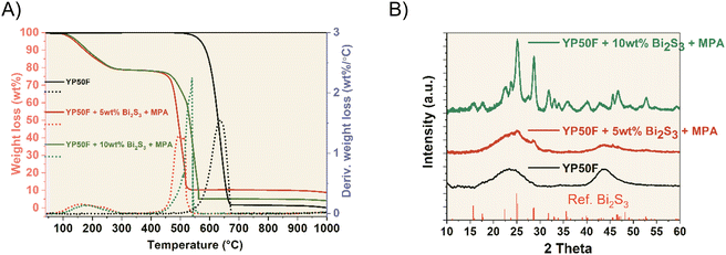
In this case, the TGA analysis of the MPA-treated samples showed similar results to the previous ones, with the addition of a mass drop at 240 °C attributed to the presence of MPA ligands. The amount of MPA on both samples is approximately 10 wt% regardless of the amount of NCs. The remaining % weight, attributed to NCs, is 3.5% and 9.0%, respectively (Fig. 4A), similar to the values obtained for the hybrids without MPA. Moreover, the XRD patterns of the MPA-treated hybrids are similar to YP50F + Bi2S3 samples (Fig. 4B). The peaks of the hybrid samples match the Bi2S3 NCs reference and become more visible for the 10 wt% Bi2S3 + MPA sample. NCs crystalline structure seems to be unaffected by the MPA ligand exchange treatment. SEM and TEM images suggest a homogeneous coverage of the YP50F surface with the NCs. There are no clear differences between the hybrids with and without MPA either on SEM (Fig. S3†) or on TEM (Fig. S1†). Additionally, EDX analysis shows an increase of O and S compared to their respective untreated hybrids, which is consistent with the addition of the MPA carboxylic and thiol groups (Table 1). Additionally, elemental mapping was carried out (Fig. S4†). It can be seen that Bi and S elements are well-dispersed in the composites.
Additionally, XPS analysis was performed to understand the bonding of the MPA molecule to the Bi2S3 NCs. In this case, the same 2 components are detected in the Bi 4f region, and a new component appears in the S 2p region at 163.6 eV for the YP50F + 5 wt% Bi2S3 + MPA sample and at 163.9 eV for the YP50F + 10 wt% Bi2S3 + MPA sample, which is attributed to sulphur from the MPA molecules.28 Furthermore, Bi–O/Bi–S ratios increased up to 7.2 for the YP50F + 5 wt% Bi2S3 + MPA and 2.9 for the YP50F + 10 wt% Bi2S3 + MPA, with regard to the hybrids without the MPA treatment (3.2 and 2.2). This suggests that the MPA molecules are mainly bonding through their carboxylic groups to the NCs, creating new Bi–O bonds (Fig. 5).
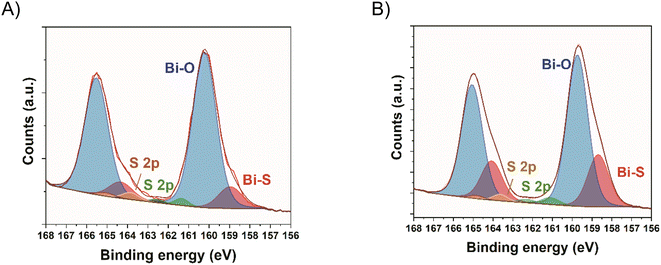 | ||
| Fig. 5 High resolution Bi 4f core spectra of (A) YP50F + 5 wt% Bi2S3 + MPA hybrid and (B) YP50F + 10 wt% Bi2S3 + MPA hybrid. | ||
Moreover, the successful incorporation of MPA was further confirmed by FTIR spectra. Slightly more pronounced bands at 1700 cm−1, attributed to the carboxylic acid C![[double bond, length as m-dash]](https://www.rsc.org/images/entities/char_e001.gif) O vibration, and at 1540 cm−1, attributed to bounded carboxylates,30 are detected for the materials treated with MPA (Fig. S5†). This is in line with the XPS analysis, pointing to a bonding between MPA and Bi2S3 NCs through the carboxylate group.
O vibration, and at 1540 cm−1, attributed to bounded carboxylates,30 are detected for the materials treated with MPA (Fig. S5†). This is in line with the XPS analysis, pointing to a bonding between MPA and Bi2S3 NCs through the carboxylate group.
The physicochemical characterisation of the activated carbon confirmed its successful modification to be used as electrochemical capacitor electrodes. Although the nanocrystals occupy certain space and mass within the electrode composite, BET measurements indicate only an insignificant drop of the surface area after their addition (1592 vs. 1680 m2 g−1 for YP50F + 10 wt% Bi2S3vs. pristine YP50F) (Fig. S6†). This result might suggest that the nanocrystals extend accessible surface area, which enable additional nitrogen adsorption.42
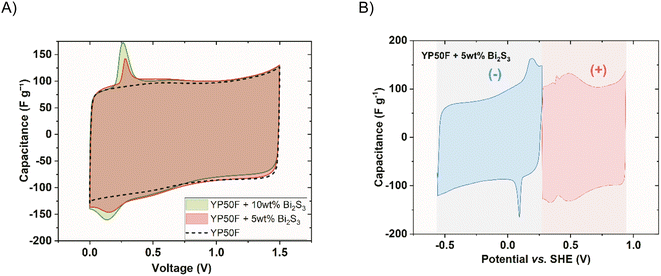
Symmetric cells using the electrodes made of commercial Kuraray YP50F carbon (of microporous type) containing the nanocrystals in two different compositions (5 wt% and 10 wt%) were constructed. Fig. 6A presents the response from the two-electrode cyclic voltammetry experiment of these cells in comparison to the pristine one within the cell voltage of 1.5 V. The additional capacitance that originated from the redox reaction of Bi2S3 NCs is insignificant compared to that of the double layer. The fingerprint of the nanocrystal was observed as a small, reversible peak at a low voltage of 0.2 V. It increased with the loading of Bi2S3. At the same time, Bi2S3 NCs do not disturb the rectangular double-layer shape. The capacitive response during the discharge of 10 wt% Bi2S3 composite is slightly lower. This might be due to the slight blockage of porosity by the sulphide. A more thorough description of the nanocrystal activity can be obtained by analysing the response of single electrodes (Fig. 6B). Clearly formed quasi-reversible peak, centred at 0.15 V vs. SHE (close to E0, i.e., electrode potentials of the discharged cell) can be noted, which is related to the presence of NCs. The voltammograms of both electrodes for the pristine and 10 wt% Bi2S3 capacitor can be seen in the supplementary data in Fig. S7.†
It is worth noting that the mentioned peak at 0.15 V vs. SHE is not initially present, but it appears and grows within several cycles of cell polarizations up to 1.5 V. Usually, in the field of the electrochemical capacitors and energy storage devices, CV curves are shown for the pre-matured cell, where the equilibrium is attained. However, deep understanding of Bi2S3 activity can be obtained while analysing the behaviour starting from the first cycle after the capacitor assembly. Fig. 7 shows the 1st and 90th voltammetry cycle within the negative electrode potential range, when the capacitor cell is polarized to 1.5 V. The first negative scan was characterized by an irreversible peak centred at −0.42 V vs. SHE and a gradually diminishing peak at −0.27 V vs. SHE. According to Pourbaix diagrams13 the first peak is attributed to the reduction of Bi2O3 to elemental bismuth with the formation of hydroxide ions. Although the main chemical compound used in the study is sulphide (not oxide), a substantial amount of oxide on the surface of Bi2S3 nanocrystals was detected, using XPS, where Bi2O3 is the most stable that could be formed during the material synthesis pathway. On an occasion, a reduced form of bismuth sulphide hydroxide (Bi2S3OH) can be formed. The reduction of Bi3+ to Bi2+ cannot be excluded. This peak (−0.42 V vs. SHE) is relatively big and sharp, meaning good initial availability of the substrate at the electrode/electrolyte interface. Additionally, this peak appears only during the first scan and not during consecutive scans, which means that it undergoes an irreversible transition entirely. The second reaction is related to Bi2S3 reduction (bismuth plating), liberating S2− ions. The oxidation of elemental bismuth is rather impossible in these conditions as the negative electrode does not reach enough positive potential for the reaction to occur. Additionally, the acidity is not strong enough to produce Bi3+ ions. During the anodic scan, the peak formed at 0.25 V vs. SHE is attributed to the oxidation of the free S2− ions, which were made available during the Bi2S3 reduction reaction. The following cycles are associated with a new peak related to sulphur reduction (0.09 V vs. SHE), which is reversible. Moreover, Bi2S3 reduction transforms progressively to a small peak, shifting towards more positive potentials, appearing at −0.11 V vs. SHE. The 90th cycle is free from water reduction reaction owing to a significant hydrogen evolution overpotential due to preceded bismuth plating.43 The proposed mechanism seems valid, where the Bi2S3 nanocrystals served as a solid-state source of ions for the reversible redox reaction. As the Bi2S3 salt possesses semi-conductive properties and has a solubility product, Ksp = 1.2 × 10−98, it implies that its equilibrium is shifted extremely to the left. Thus, the redox response of its ions is adequately low.
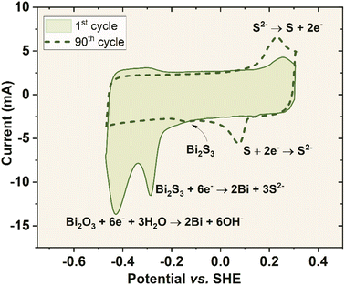 | ||
| Fig. 7 1st and 90th voltammetry curves of the negative electrode of system YP50F + 10 wt% Bi2S3 (polarized to 1.5 V) in 1 mol L−1 Li2SO4 at 2.5 mV s−1. | ||
To support this theory, the capacitor was cycled to the voltage at which the reaction Bi2S3 + 6e− → 2Bi + 3S2− could not have a chance to occur and Bi2S3 was dissolved in the electrolyte. To achieve this, the capacitor cell reached only 0.8 V (Fig. S8†). Although the equilibrium potential of the sulphur redox reaction (−0.2 V vs. SHE) was also well kept within the operational potential range of the negative electrode with constraint potential range, no electrochemical response of this redox couple was detected. It confirmed that Bi2S3 was not decomposed, and no S2− ions were liberated. The proposed reactions and mechanisms were confirmed by means of sulphur analysis in pristine and matured electrodes. Table S1† presents the results, where the sulphur content was decreased in the negative electrode of the operated capacitors. The remaining amount of sulphur was then transferred to the electrolyte or partially deposited in the positive electrode (the amount of sulphur in the positive electrode also increases). As a result of the reaction Bi2S3 + 6e− → 2Bi + 3S2−, a film of metallic bismuth was deposited on the electrode and, in turn, within the separator (Fig. S9†). It was detected via the bismuth characteristic reactions, by leaching into the Bi3+ (with concentrated nitric acid) and then precipitation of the insoluble bismuth(III) iodide (using sodium iodide solution), which dissolved the surplus reagent, forming an orange transparent solution of the [BiI4]− complex ions. The electrodeposition process slightly decreased the coulombic efficiency of the capacitor charge/discharge process as the products of the reaction might go away from the electrode/electrolyte interface. Moreover, the layer of bismuth on the separator can act as an additional contribution to increase the hydrogen overpotential.
The low solubility, semi-conductive properties, and the ability of both elements in bismuth(III) sulphide to undergo redox processes provided an interesting compound to be used for capacitor property (voltage range, capacity) enhancement. Nevertheless, the benefit it provides in terms of increased capacity is very low. This is most probably due to the solubility constant of the compound (1 × 10⁻¹⁵ mol L−1). In order to increase the redox response, the availability of the redox substrates had to be then increased. For this purpose, a ligand exchange treatment was applied to the carbon + NCs hybrids. It was decided to use 3-mercaptopropionic acid (MPA) as this ligand can easily bond to the NCs by substituting the stabilizing oleic acid chains (Fig. S10†). The presence of polar groups such as thiol and carboxylic acid enhances the wettability between the aqueous electrolyte and the material enabling more efficient use of Bi2S3, thus increasing the availability of the substrates for the reaction Bi2S3 + 6e− → 2Bi + 3S2−. Fig. 8A shows the response of the cell containing electrodes with Bi2S3 in the presence of an MPA ligand (polarized to 1.5 V). It is compared to the case where bare NCs are present (with the same mass loading). A new reversible peak was formed at 0.5 V of cell voltage in addition to the peak previously present when no MPA was engaged. It must be noted that the cell with MPA only (YP50F + MPA) did not indicate any redox response, which excludes its activity alone.
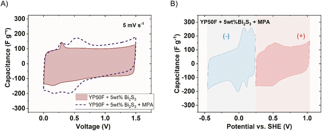
Observing the response of single electrodes (Fig. 8B), strong reversible peaks can be remarked in the negative electrode potential range, centred at 0.1 V and 0.2 vs. SHE. They emerge at the same potential as the peaks of bare Bi2S3 (without MPA), but with a more intense response, even if the mass loading of the redox active substance was the same. Moreover, the activity is depicted as two distinct peaks partially overlapping each other, indicating that two redox reactions occur, both upon reduction and oxidation. They can be attributed to the activity of Bi2S3 and Bi2O3, which react with a 100 mV difference. According to XPS measurements (Fig. 5), Bi2S3 when present in the carbon matrix displays bonding between Bi–S, but also Bi–O, which, in fact, is even more abundant than Bi–S. The increased wettability owing to the incorporation of MPA enabled Bi2S3 to be exploited more efficiently. Additionally, the MPA reduced the ESR (equivalent series resistance) from 0.6 Ω to 0.45 Ω. A substantial current increase is observed at the negative potential limit of the negative electrode. It resembles the onset of a solvent (water) reduction reaction. This reaction onset is found at around −0.2 V vs. SHE. According to the Pourbaix diagram of water, it indicates a rather neutral (or slightly acidic) pH in the vicinity of the negative electrode. This was confirmed using a pH indicator after the capacitor disassembly. Surprisingly, the overpotential for hydrogen evolution on this electrode was not observed. The positive electrode, on the other hand, is characterized by the operation to the upper potential limit exceeding 1.0 V vs. SHE, still without significant current increase characteristics of the solvent decomposition reaction. It suggested the formation of an acidic environment. This, in turn, impacts the negative electrode, hindering its alkalisation. This finding is supported by the presence of a reversible peak at around 0.45 V vs. SHE on the positive electrode, which is attributed to the quinone/hydroquinone redox pair, which readily forms in an acidic environment. The acidic environment can originate from a carboxylic group in the ligand molecule (3-mercaptopropionic acid), although being a weak acid. The detailed view of the negative electrodes for the system with and without MPA is presented in Fig. S11.†
The addition of redox contribution from Bi2S3 nanocrystals to the negative electrode in the presence of MPA increased the negative electrode capacitance more than twice. At the same time, the device capacitance increased only by 20% (100 F g−1 to 120 F g−1). In order to significantly boost the device capacitance (C), the respective capacitances of both electrodes (C+, C−) should be certainly high, but also as close to each other as possible. In this mode, none of the electrodes will be the capacitance-limiting ones according to the eqn (4):
 | (4) |
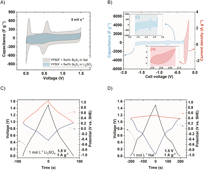
To achieve this goal, another redox pair was introduced to increase the capacitance of the positive electrode. A well-known compound that shows activity in the positive electrode potential region is an iodide salt.4,23 For this purpose, it was decided to substitute the Li2SO4 electrolyte with NaI. The choice of the cation of the salt was not considered crucial for the capacitor performance. Fig. 9 shows the impact of the electrolyte replacement.
The iodide electrolyte increased the apparent capacitance in the two-electrode device (Fig. 9A) in the whole voltage range. The reversible peak of Bi2S3 activity (observed at around 0.5 V) was significantly enlarged. This could be due to the boost resulting from mutual high-capacitance potential regions of both electrodes. The corresponding galvanostatic charge/discharge (GCD) cycles of the systems (−) YP50F + 5 wt% Bi2S3 + MPA//YP50F (+) in 1 mol L−1 Li2SO4 and NaI are shown in Fig. 9C and D. Additionally, the individual electrodes of the systems are presented. The boost of instantaneous capacitance (voltage plateau) was observed at around 0.5 V, revealing its partial battery-like behaviour. The double-layer capacitance (visible in the region of the negative electrode in the inset of Fig. 9B) was, of course, unchanged, while the additional capacitance besides Bi2S3, comes from iodides (visible in the inset of Fig. 9B). The capacitance boost was therefore observed when the instantaneous capacitance values of electrodes are comparable. To intensify this effect, the capacitance of the negative electrode must be increased with respect to the positive electrode. A straightforward way to achieve this goal is the introduction of electrode mass ratio to the capacitor cell, where the mass of the negative electrode will be higher than the mass of the positive one. In this way, the device gravimetric capacitance expressed per average mass of the electrode should be higher. Fig. 10 shows the comparison of the capacitance achieved at different current rates when different mass ratios of electrodes were applied.
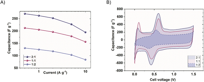 | ||
| Fig. 10 Different negative-to-positive electrode mass ratios (1 mol L−1 NaI), (A) rate capability comparison of the (−) YP50F + 5 wt% Bi2S3 + MPA//YP50F (+) and (B) cyclic voltammograms (10 mV s−1). | ||
Clearly, increasing the respective masses of the negative electrodes enabled the reaching of higher capacitance values (Fig. 10A). The capacitance increase at 0.5 A g−1 for the case where m−![[thin space (1/6-em)]](https://www.rsc.org/images/entities/char_2009.gif) :
:![[thin space (1/6-em)]](https://www.rsc.org/images/entities/char_2009.gif) m+ = 2
m+ = 2![[thin space (1/6-em)]](https://www.rsc.org/images/entities/char_2009.gif) :
:![[thin space (1/6-em)]](https://www.rsc.org/images/entities/char_2009.gif) 1 was 24%, while m−
1 was 24%, while m−![[thin space (1/6-em)]](https://www.rsc.org/images/entities/char_2009.gif) :m+ = 1
:m+ = 1![[thin space (1/6-em)]](https://www.rsc.org/images/entities/char_2009.gif) :
:![[thin space (1/6-em)]](https://www.rsc.org/images/entities/char_2009.gif) 2 was characterised by a decrease of 38% of the initial capacitance value. Moreover, the decrease of capacitance with time was more intense for m−
2 was characterised by a decrease of 38% of the initial capacitance value. Moreover, the decrease of capacitance with time was more intense for m−![[thin space (1/6-em)]](https://www.rsc.org/images/entities/char_2009.gif) :
:![[thin space (1/6-em)]](https://www.rsc.org/images/entities/char_2009.gif) m+ = 2
m+ = 2![[thin space (1/6-em)]](https://www.rsc.org/images/entities/char_2009.gif) :
:![[thin space (1/6-em)]](https://www.rsc.org/images/entities/char_2009.gif) 1. It is already visible that m−
1. It is already visible that m−![[thin space (1/6-em)]](https://www.rsc.org/images/entities/char_2009.gif) :
:![[thin space (1/6-em)]](https://www.rsc.org/images/entities/char_2009.gif) m+ = 2
m+ = 2![[thin space (1/6-em)]](https://www.rsc.org/images/entities/char_2009.gif) :
:![[thin space (1/6-em)]](https://www.rsc.org/images/entities/char_2009.gif) 1 shows a steeper capacitance decrease with increasing discharge current. This is caused by the resistance of the thick-negative electrode containing NCs, which starts to prevail and leads to deteriorated performance, due to its semiconducting properties. Increasing the electrode mass ratio to 3
1 shows a steeper capacitance decrease with increasing discharge current. This is caused by the resistance of the thick-negative electrode containing NCs, which starts to prevail and leads to deteriorated performance, due to its semiconducting properties. Increasing the electrode mass ratio to 3![[thin space (1/6-em)]](https://www.rsc.org/images/entities/char_2009.gif) :
:![[thin space (1/6-em)]](https://www.rsc.org/images/entities/char_2009.gif) 1 and more results in an extremely high resistive response. Fig. 10B shows the voltammogram, where the origin of the capacitance can be distinguished. It can be seen that by changing the mass ratio, the relative peak height changes proportionally, but also the double-layer capacitance changes, respectively. This is mainly due to the boost (or decrease) of sulphur response at the negative electrode and satisfaction of eqn (3). The peaks observed close to 0 V evolve as a result of electrode potential changes at the discharged capacitor and are not formed owing to mass balancing.
1 and more results in an extremely high resistive response. Fig. 10B shows the voltammogram, where the origin of the capacitance can be distinguished. It can be seen that by changing the mass ratio, the relative peak height changes proportionally, but also the double-layer capacitance changes, respectively. This is mainly due to the boost (or decrease) of sulphur response at the negative electrode and satisfaction of eqn (3). The peaks observed close to 0 V evolve as a result of electrode potential changes at the discharged capacitor and are not formed owing to mass balancing.
The behaviour of a double redox capacitor operating in the solution of redox-active electrolyte (NaI) instead of neutral sulphate (Li2SO4) is certainly different. In this case, as the system becomes more complex, the mutual interference of the two redox pairs (iodides and sulphides) requires consideration. For that purpose, Raman spectroscopy was performed in the operando mode to present behaviour of negative and positive electrodes (Fig. 11). Since the most important changes (especially the irreversible ones) are noted during initial cycles, spectra are shown for the first three voltammetry cycles after the capacitor assembly. The spectra of both electrodes differ considerably. The D and G bands, formed at 1350 and 1600 cm−1, respectively, are associated with disordered carbon microstructure changes, related to carbon–hydrogen sorption, thoroughly described elsewhere.21 The bands formed in the Raman shift between 50 and 100 cm−1 (observed in the inset) at the negative electrode are not detected for pristine carbon and, therefore, are ascribed to the activity of Bi2S3. The peaks formed during the first cycle and the first reaction (which is a reduction) are indicated by the peak on the two-electrode voltammetry curves shown in the time domain. The mentioned peaks are intense between the reduction and oxidation reactions, where S2− ions are present, and disappear between oxidation and reduction, where elemental sulphur is in its stable form. This suggests and confirms that a reversible electrodeposition process involving the phase change occurs at the negative electrode. The positive electrode, on the other hand, is characterised by almost stable D and G bands, after their intensity increases to reach saturation after the first cycle. Later, only minor intensity changes were observed in line with cycling, suggesting changes in carbon microstructure. A more important observation was in the region between 100 and 175 cm−1, where the characteristic vibrations due to I3− and I5− polyiodides were found, respectively.44 These bands are observed in high positive voltages only, indicating that in the discharged state, iodides or molecular iodine are more preferred forms.
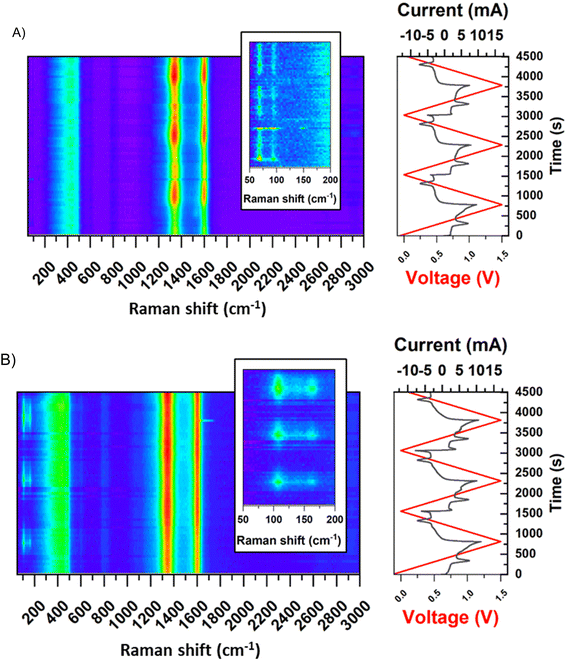 | ||
| Fig. 11 Raman spectra in operando mode for the system (−) YP50F + 5 wt% Bi2S3 + MPA//YP50F (+) (1 mol L−1 NaI), (A) negative electrode, (B) positive electrode. (2 mV s−1). | ||
In addition to the capacitance enhancement owing to the presence of Bi2S3 and iodides, the self-discharge of the cell was reduced considerably. This could be achieved owing to redox processes occurring at both electrodes, which blocked their potential against voltage drop. Fig. 12 shows the self-discharge of the cell, which did not include voltage hold before reaching open circuit conditions. First, it is seen that a positive electrode, in which iodides are active, was characterised by almost no self-discharge. This is due to the confinement of iodides in the porosity of activated carbon, which also has been already well described.22,45 A negative electrode, in which the sulphur activity is present, does not immediately discharge as the phase transition reaction partially keeps the potential at very negative values.
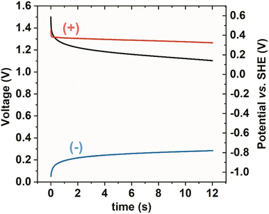 | ||
| Fig. 12 Self-discharge of the system (−) YP50F + 5 wt% Bi2S3 + MPA//YP50F (+) (1 mol L−1 NaI). Black – whole capacitor, red – positive electrode, blue – negative electrode. | ||
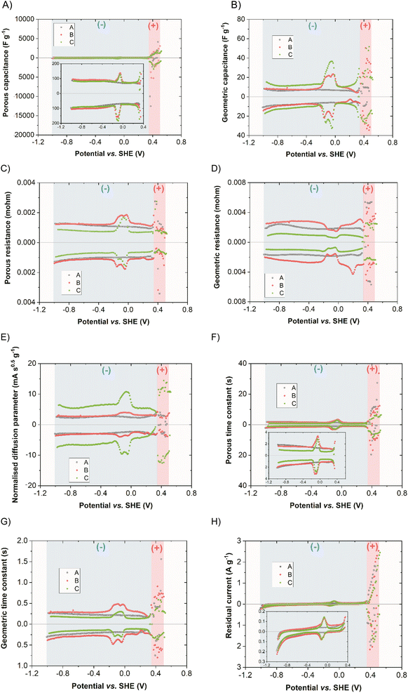
To quantify the capacitive contribution of different charge-storing mechanisms in this double redox capacitor, the SPECS technique was performed. It has the advantage over other electrochemical techniques such as CA or CV, as it allows for additional information to be obtained. Moreover, the potential shift in SPECS is gentle. This allows for increased data resolution and accuracy, which, in the case of the double redox capacitor, seems vital. It ultimately permits any redox reactions to occur as well as balanced ion redistribution within the pores that actively participate in EDL formation. Total current (IT), which is calculated according to eqn (3), can be further broken down into individual components: IT = IP + IG + ID + IE where IP = current corresponding to EDL formation in the porous structure of the electrode, IG = current corresponding to EDL formation on easily accessible electrode surface for the electrolyte, ID = current corresponding to ion diffusion and IE = residual/equilibrium current. These currents can be calculated into corresponding capacitances by dividing the area of each current curve by the active mass of the electrode and the potential step. In this way, one may separate the total system capacitance (CT) into individual capacitances, namely: the electric double-layer capacitance (CEDL) component, which consists of both geometric (CG) and porous capacitances (CP). Additionally, capacitance resulting from ion diffusion (CD) and residual capacitance (CR) related to redox reactions and any side reactions that might occur, such as electrolyte decomposition, were separated. Thus, CT = CP + CG + CD + CE.40,46,47Fig. 13 represents the breakdown of each parameter obtained from the SPECS measurements of positive (red region) and negative (blue region) electrodes for systems A, B, and C. Since the positive electrode, in which the operation of iodides has been extensively covered in the literature, e.g., using other techniques such as electrochemical quartz crystal microbalance (EQCM),22 the focus here is on the negative electrode with Bi2S3 NCs activity. As expected, the main contribution to the total capacitance in all systems is made by CP, which exceeds CG, as seen in Fig. 13A and B, respectively. This comes as no surprise, as activated carbon is characterised by a strongly developed specific surface area. The share of CG is significantly lower, which stems from the poorly developed electrode surface in direct contact with the electrolyte. At the same time, the contribution of CEDL in all cases is comparable, where a slight increase of capacitance is observed in the double redox systems (due to the occurrence of a reversible redox reaction). The CEDL response should be symmetrical about the Y axis for capacitive systems, but it increases in the potential regions where redox occurs. It can be assumed that since redox reaction induces charge transfer in the specifically adsorbed ions, it affects the formation of EDL itself. At the same time, this response cannot be differentiated from CEDL and subsequently, an increase is noted in those regions. It should be also noted that the redox on the negative electrode comes directly from the bismuth sulphide modified electrode rather than from the electrolytic solution, as proved by system A, which lacks this characteristic and is purely capacitive. Upon closer analysis of the redox peaks in the double redox system with MPA (system B), one can distinguish two distinct peaks, indicating that two redox reactions occur, both upon reduction and oxidation. This is in accordance with what was already discussed and attributed to the activity of Bi2S3 and Bi2O3. At the same time, EDL formation associated with redox seems to be slightly more facilitated on the surface of the electrode rather than inside the pores. This can be seen in Fig. 13C and D, in which the value of porous resistance increases while the geometric one decreases in the potential region in which redox reactions occur. Moreover, this is in accordance with the porous time constant (system capacitance multiplied by resistance) parameter in which the value was visibly higher than the geometric one, yet it increased for double redox systems indicating that EDL was formed more slowly in those redox regions and that the ion transfer was somewhat delayed (normalized diffusion parameter). The contribution of residual reactions, Fig. 13H, is visible at the potentials where the processes attributed to electrolyte decomposition and oxidation-reduction of compounds cause an increase in the current response. This again is as expected in the case of the bismuth sulfide-modified electrode coupled with an aqueous electrolyte. One might also see differences in-between double redox systems with and without MPA by examining individual SPECS parameters. The addition of MPA to the electrode material yields overall higher specific capacitance (∼by 10%) when coupled with 1 mol L−1 NaI at the negative electrode (Fig. S12†), attributed to the improved diffusion parameter as well as higher CT and CEDL response of the system. This would imply that the incorporation of MPA can additionally help in optimising the electrochemical performance of the double redox capacitor. It is also necessary to add that the YP50F carbon with MPA, without Bi2S3 NCs in composition, does not exhibit any redox response.
In addition to the mechanism study, performance metrics, such as energy and power were evaluated. The specific energy of the system (−) YP50F + 5 wt% Bi2S3 + MPA//YP50F (+) (1 mol L−1 NaI) m−![[thin space (1/6-em)]](https://www.rsc.org/images/entities/char_2009.gif) :
:![[thin space (1/6-em)]](https://www.rsc.org/images/entities/char_2009.gif) m+ = 2
m+ = 2![[thin space (1/6-em)]](https://www.rsc.org/images/entities/char_2009.gif) :
:![[thin space (1/6-em)]](https://www.rsc.org/images/entities/char_2009.gif) 1 reaches 20 W h kg−1 (Fig. S13†), which can be further increased readily and even pursue the specific energy of a capacitor operating with organic electrolyte (30 W h kg−1) increasing the iodide concentration and modifying the mass ratio of electrodes. The time constant of the presented device was found in the range of 21–25 seconds, depending on the assigned technique (Fig. S14†). The precise value of RC cannot be determined due to the complex electrochemical behaviour. The long-term cycling of the system indicated an 20% capacitance decrease after 4000 galvanostatic charge/discharge cycles at 1 A g−1. At the same time, a slight resistance increase was noted, which accelerated after 2500 cycles (Fig. S15†).
1 reaches 20 W h kg−1 (Fig. S13†), which can be further increased readily and even pursue the specific energy of a capacitor operating with organic electrolyte (30 W h kg−1) increasing the iodide concentration and modifying the mass ratio of electrodes. The time constant of the presented device was found in the range of 21–25 seconds, depending on the assigned technique (Fig. S14†). The precise value of RC cannot be determined due to the complex electrochemical behaviour. The long-term cycling of the system indicated an 20% capacitance decrease after 4000 galvanostatic charge/discharge cycles at 1 A g−1. At the same time, a slight resistance increase was noted, which accelerated after 2500 cycles (Fig. S15†).
4. Conclusions
The incorporation of redox substances into electrochemical capacitors operating in an aqueous medium seems currently to be a prerequisite for the successful commercialisation of the technology. The single redox pair usually increases the specific energy of the device, however, it is still not enough to compete with the state-of-the-art capacitors operating in the organic medium. The strategy presented in this paper, where two redox couples are involved enables meeting the specific energy level of the organic capacitors. This could be possible thanks to high capacitance (250 F g−1vs. 100 F g−1), although at a lower voltage (1.5 V vs. 2.7 V). Bi2S3 presented in this work acts as a redox source for the capacitor electrode, slowly releasing the reactants for the reversible redox reaction. Due to the complexation abilities of the iodide solution for Bi3+, these ions do not deposit on the surface. What is especially important is that Bi2S3 redox reaction occurs within the negative electrode potential region. This is rarely observed in the literature. Most of the redox processes described in this field occur in the positive electrode potential region. These are for example the iodides, which are also a core of the electrolyte. Incorporating two powerful redox species, each at a separate electrode ensures a significant boost of momentary capacitance. This gives a plateau region during cycling, increasing the electrode discharge time. It is worth noting that the application of only iodides as a redox-active electrolyte restricted the cell voltage to much below 1.5 V. The reason for fading of the performance at higher voltages was the failure of the negative electrode, which had to operate in a wide potential region, extending deeply into negative potential values. This exerted high hydrogen production with inhibited hydrogen storage abilities. Here, we present stable operation at 1.5 V, which was enabled due to the incorporation of the redox process (Bi2S3) at the negative electrode, which allowed for the limitation of the negative potential reached by the (−) electrode. Raman spectroscopy provided valuable information that helped in understanding the reaction mechanisms occurring at the electrodes of (−) YP50F + 5 wt% Bi2S3 + MPA//YP50F (+) in 1 mol L−1 NaI. It confirmed that the two redox couples can operate independently, which is important from the point of view of long-term operation. An important small cell self-discharge rate, without a voltage hold period, could be achieved owing to the use of two redox couples on the respective electrodes. This solution leads to energy savings in comparison to pure EDLC capacitors, in which voltage drops quickly when no charge redistribution period is accounted for before. The dual redox capacitor presented in the paper does not require special membrane separation between the electrodes at which different redox couples are accommodated, as they operate in an immiscible mode. Iodides are generally confined in porosity, while Bi2S3 exists mainly in solid-state. Any possible formation of an insoluble deposit of BiI3 is not an issue, since it can readily become a soluble complex salt of Na2[BiI5] due to the presence of NaI in the electrolyte. Regarding S2− ions from the negative electrode, they are indeed soluble and can undergo deposition on the positive electrode. However, the highly reversible peak of sulphur (centered at 0.2 V vs. SHE) suggests its good transition efficiency, confirming that it resides well within the bulk of the negative electrode. However, slow migration towards the positive electrode can always occur. Finally, the materials used for the system construction are affordable and environmentally benign.Author contributions
Adam Slesinski – conceptualization, methodology, investigation, data curation, writing – original draft. Sylwia Sroka–methodology, investigation, visualization, writing – original draft. Sergio Aina – methodology, investigation, data curation, writing – original draft. Justyna Piwek – investigation, data curation. Krzysztof Fic – supervision, writing – review and editing. M. Pilar Lobera – supervision, writing – review and editing. Maria Bernechea – supervision, funding acquisition, project administration, writing – review and editing. Elzbieta Frackowiak – supervision, funding acquisition, project administration, writing – review and editing.Conflicts of interest
There are no conflicts of interest to declare.Acknowledgements
Authors acknowledge M-ERA.NET network, MCIN/AEI/10.13039/501100011033 (Ref. PCI2019–103637), CIBER-BBN, ICTS ‘‘NANBIOSIS’’, ICTS ELECMI node “Laboratorio de Microscopias Avanzadas”, Servicio General de Apoyo a la Investigación-SAI, Universidad de Zaragoza, National Science Centre, Poland (2018/30/Z/ST4/00901). Project 0911/SBAD/2201 is also acknowledged. The authors are grateful to Przemyslaw Galek for performing SPECS calculations.References
- N. Abas, A. Kalair and N. Khan, Review of fossil fuels and future energy technologies, Futures, 2015, 69, 31–49 CrossRef
.
- R. Kötz and M. Carlen, Principles and applications of electrochemical capacitors, Electrochim. Acta, 2000, 45(15), 2483–2498 CrossRef
.
- M. Winter and R. J. Brodd, What Are Batteries, Fuel Cells, and Supercapacitors?, Chem. Rev., 2004, 104(10), 4245–4270 CrossRef CAS PubMed
.
- P. Simon and Y. Gogotsi, Perspectives for electrochemical capacitors and related devices, Nat. Mater., 2020, 19(11), 1151–1163 CrossRef CAS PubMed
.
- F. Béguin, V. Presser, A. Balducci and E. Frackowiak, Supercapacitors: Carbons and Electrolytes for Advanced Supercapacitors, Adv. Mater., 2014, 26(14), 2283 CrossRef
.
- P. W. Ruch, D. Cericola, A. Foelske, R. Kötz and A. Wokaun, A comparison of the aging of electrochemical double layer capacitors with acetonitrile and propylene carbonate-based electrolytes at elevated voltages, Electrochim. Acta, 2010, 55(7), 2352–2357 CrossRef CAS
.
- R. E. Ruther, C.-N. Sun, A. Holliday, S. Cheng, F. M. Delnick, T. A. Zawodzinski and J. Nanda, Stable Electrolyte for High Voltage Electrochemical Double-Layer Capacitors, J. Electrochem. Soc., 2016, 164(2), A277–A283 CrossRef
.
- E. Perricone, M. Chamas, L. Cointeaux, J. C. Leprêtre, P. Judeinstein, P. Azais, F. Béguin and F. Alloin, Investigation of methoxypropionitrile as co-solvent for ethylene carbonate based electrolyte in supercapacitors. A safe and wide temperature range electrolyte, Electrochim. Acta, 2013, 93, 1–7 CrossRef CAS
.
- Q. Abbas, B. Gollas and V. Presser, Reduced Faradaic Contributions and Fast Charging of Nanoporous Carbon Electrodes in a Concentrated Sodium Nitrate Aqueous Electrolyte for Supercapacitors, Energy Technol., 2019, 7(9), 1900430 CrossRef PubMed
.
- M. Pang, S. Jiang, J. Zhao, S. Zhang, R. Wang, N. Li, R. Liu, Q. Pan, W. Qu and B. Xing, "Water-in-salt" electrolyte enhanced high voltage aqueous supercapacitor with carbon electrodes derived from biomass waste-ground grain hulls, RSC Adv., 2020, 1(58), 35545–35556 RSC
.
- G.-H. Sun, K.-X. Li and C.-G. Sun, Application of 1-ethyl-3-methylimidazolium thiocyanate to the electrolyte of electrochemical double layer capacitors, J. Power Sources, 2006, 162(2), 1444–1450 CrossRef CAS
.
- V. V. Chaban and O. V. Prezhdo, How Toxic Are Ionic Liquid/Acetonitrile Mixtures?, J. Phys. Chem. Lett., 2011, 2(19), 2499–2503 CrossRef CAS
.
-
M. Pourbaix, Atlas of Electrochemical Equilibria in Aqueous Solutions, National Association of Corrosion Engineers, Houston, Texas, 2nd English edn, 1974 Search PubMed
.
- C.-C. Hu and C.-C. Wang, Effects of electrolytes and electrochemical pretreatments on the capacitive characteristics of activated carbon fabrics for supercapacitors, J. Power Sources, 2004, 125(2), 299–308 CrossRef CAS
.
- B. Akinwolemiwa, C. Peng and G. Z. Chen, Redox Electrolytes in Supercapacitors, J. Electrochem. Soc., 2015, 162(5), A5054–A5059 CrossRef CAS
.
- G. Shul and D. Bélanger, Self-discharge of electrochemical capacitors based on soluble or grafted quinone, Phys. Chem. Chem. Phys., 2016, 18(28), 19137–19145 RSC
.
- P. Bujewska, B. Gorska and K. Fic, Redox activity of selenocyanate anion in electrochemical capacitor application, Synth. Met., 2019, 253, 62–72 CrossRef CAS
.
- S.-E. Chun, B. Evanko, X. Wang, D. Vonlanthen, X. Ji, G. D. Stucky and S. W. Boettcher, Design of aqueous redox-enhanced electrochemical capacitors with high specific energies and slow self-discharge, Nat. Commun., 2015, 6(1), 7818 CrossRef CAS PubMed
.
- G. Lota and E. Frackowiak, Striking capacitance of carbon/iodide
interface, Electrochem. Commun., 2009, 11(1), 87–90 CrossRef CAS
.
- E. Frackowiak, M. Meller, J. Menzel, D. Gastol and K. Fic, Redox-active electrolyte for supercapacitor application, Faraday Discuss., 2014, 172, 179–198 RSC
.
- J. Menzel, E. Frąckowiak and K. Fic, Agar-based aqueous electrolytes for electrochemical capacitors with reduced self-discharge, Electrochim. Acta, 2020, 332, 135435 CrossRef CAS
.
- A. Platek-Mielczarek, E. Frackowiak and K. Fic, Specific carbon/iodide interactions in electrochemical capacitors monitored by EQCM technique, Energy Environ. Sci., 2021, 14(4), 2381–2393 RSC
.
- J. Menzel, K. Fic, M. Meller and E. Frackowiak, The effect of halide ion concentration on capacitor performance, J. Appl. Electrochem., 2014, 44(4), 439–445 CrossRef CAS
.
- E. Frackowiak, K. Fic, M. Meller and G. Lota, Electrochemistry Serving People and Nature: High-Energy Ecocapacitors based on Redox-Active Electrolytes, ChemSusChem, 2012, 5(7), 1181–1185 CrossRef CAS PubMed
.
- H. Lu, A. Lipatov, S. Ryu, D. J. Kim, H. Lee, M. Y. Zhuravlev, C. B. Eom, E. Y. Tsymbal, A. Sinitskii and A. Gruverman, Ferroelectric tunnel junctions with graphene electrodes, Nat. Commun., 2014, 5(1), 5518 CrossRef CAS PubMed
.
- S. Vadivel, B. Paul, A. Habibi-Yangjeh, D. Maruthamani, M. Kumaravel and T. Maiyalagan, One-pot hydrothermal synthesis of CuCo2S4/RGO nanocomposites for visible-light photocatalytic applications, J. Phys. Chem. Solids, 2018, 123, 242–253 CrossRef CAS
.
- G. Nie, X. Lu, J. Lei, L. Yang and C. Wang, Facile and controlled synthesis of bismuth sulphide nanorods-reduced graphene oxide composites with enhanced supercapacitor performance, Electrochim. Acta, 2015, 154, 24–30 CrossRef CAS
.
- A. Munir, T. Haq, A. Qurashi, H. Rehman, A. Ul-Hamid and I. Hussain, Ultrasmall Ni/NiO Nanoclusters on Thiol-Functionalized and -Exfoliated Graphene Oxide Nanosheets for Durable Oxygen Evolution Reaction, ACS Appl. Energy Mater., 2019, 2(1), 363–371 CrossRef CAS
.
- R. Mukkabla, M. Deepa and A. K. Srivastava, Poly(3,4-ethylenedioxypyrrole) Enwrapped Bi2S3 Nanoflowers for Rigid and Flexible Supercapacitors, Electrochim. Acta, 2015, 164, 171–181 CrossRef CAS
.
- S. G. Lanas, M. Valiente, M. Tolazzi and A. Melchior, Thermodynamics of Hg2+ and Ag+ adsorption by 3-mercaptopropionic acid-functionalized superparamagnetic iron oxide nanoparticles, J. Therm. Anal. Calorim., 2019, 136(3), 1153–1162 CrossRef CAS
.
- J. Y. Hwang, M. F. El-Kady, M. Li, C.-W. Lin, M. Kowal, X. Han and R. B. Kaner, Boosting the capacitance and voltage of aqueous supercapacitors via redox charge contribution from both electrode and electrolyte, Nano Today, 2017, 15, 15–25 CrossRef CAS
.
- K. M. Lee and K. Kim, Electrode potentials in electrochemical double-layer capacitors with asymmetric electrode thicknesses, Electrochim. Acta, 2022, 141364 CrossRef CAS
.
- B. Andres, A.-C. Engström, N. Blomquist, S. Forsberg, C. Dahlström and H. Olin, Electrode Mass Balancing as an Inexpensive and Simple Method to Increase the Capacitance of Electric Double-Layer Capacitors, PLoS One, 2016, 11(9), e0163146 CrossRef PubMed
.
- B. Evanko, S. J. Yoo, S.-E. Chun, X. Wang, X. Ji, S. W. Boettcher and G. D. Stucky, Efficient Charge Storage in Dual-Redox Electrochemical Capacitors through Reversible Counterion-Induced Solid Complexation, J. Am. Chem. Soc., 2016, 138(30), 9373–9376 CrossRef CAS PubMed
.
- D. P. Chatterjee and A. K. Nandi, A review on the recent advances in hybrid supercapacitors, J. Mater. Chem. A, 2021, 9(29), 1588–15918 RSC
.
- K. Ghosh and S. K. Srivastava, Superior supercapacitor performance of Bi2S3 nanorod/reduced graphene oxide composites, Dalton Trans., 2020, 49(46), 16993–17004 RSC
.
- A. Moyseowicz and A. Moyseowicz, One-Pot Synthesis of Bismuth Sulfide Nanostructures as an Active Electrode Material for Aqueous Hybrid Capacitors, Energies, 2021, 14, 2670 CrossRef CAS
9.
- M. Bernechea, Y. Cao and G. Konstantatos, Size and bandgap tunability in Bi2S3 colloidal nanocrystals and its effect in solution processed solar cells, J. Mater. Chem. A, 2015, 3(41), 2642–2648 RSC
.
- N. G. García-Peña, D. Díaz, G. Rodríguez-Gattorno, I. Betancourt and I. Zumeta-Dubé, Facile synthesis of rod-shaped bismuth sulphide@graphene oxide (Bi2S3@GO) composite, Mater. Chem. Phys., 2018, 219, 376–389 CrossRef
.
- M. F. Dupont and S. W. Donne, Separating Faradaic and Non-Faradaic Charge Storage Contributions in Activated Carbon Electrochemical Capacitors Using Electrochemical Methods: I Step Potential Electrochemical Spectroscopy, J. Electrochem. Soc., 2015, 162(7), A1246–A1254 CrossRef CAS
.
- M. Forghani and S. W. Donne, Modification of the Step Potential Electrochemical Spectroscopy Analysis Protocol to Improve Outcomes, J. Electrochem. Soc., 2019, 166(13), A2727–A2735 CrossRef CAS
.
- H. Shen, Z. Shao, Q. Zhao, M. Jin, C. Shen, M. Deng, G. Zhong, F. Huang, H. Zhu, F. Chen and Z. Luo, Facile synthesis of novel three-dimensional Bi2S3 nanocrystals capped by polyvinyl pyrrolidone to enhance photocatalytic properties under visible light, J. Colloid Interface Sci., 2020, 573, 115–122 CrossRef CAS PubMed
.
- Y. M. Wu, W. S. Li, X. M. Long, F. H. Wu, H. Y. Chen, J. H. Yan and C. R. Zhang, Effect of bismuth on hydrogen evolution reaction on lead in sulfuric acid solution, J. Power Sources, 2005, 144(2), 338–345 CrossRef CAS
.
- Q. Abbas, H. Fitzek, V. Pavlenko and B. Gollas, Towards an optimized hybrid electrochemical capacitor in iodide based aqueous redox-electrolyte: shift of equilibrium potential by electrodes mass-balancing, Electrochim. Acta, 2020, 337, 135785 CrossRef CAS
.
- P. Przygocki, Q. Abbas, P. Babuchowska and F. Béguin, Confinement of iodides in carbon porosity to prevent from positive electrode oxidation in high voltage aqueous hybrid electrochemical capacitors, Carbon, 2017, 125, 391–400 CrossRef CAS
.
- M. F. Dupont and S. W. Donne, A Step Potential Electrochemical Spectroscopy Analysis of Electrochemical Capacitor Electrode Performance, Electrochim. Acta, 2015, 167, 268–277 CrossRef CAS
.
- P. Galek, P. Bujewska, S. Donne, K. Fic and J. Menzel, New insight into ion dynamics in nanoporous carbon materials: An application of the step potential electrochemical spectroscopy (SPECS) technique and electrochemical dilatometry, Electrochim. Acta, 2021, 377, 138115 CrossRef CAS
.
Footnote |
| † Electronic supplementary information (ESI) available. See DOI: https://doi.org/10.1039/d2ta09541f |
| This journal is © The Royal Society of Chemistry 2023 |

