
 Open Access Article
 This Open Access Article is licensed under a
 Creative Commons Attribution 3.0 Unported Licence
Insights into the electronic structure of Fe–Ni thin-film catalysts during the oxygen evolution reaction using operando resonant photoelectron spectroscopy†
Garlef
Wartner
 ab,
Dennis
Hein
ab,
Arno
Bergmann
c,
Robert
Wendt
d,
Beatriz
Roldan Cuenya
c and
Robert
Seidel
*ab
ab,
Dennis
Hein
ab,
Arno
Bergmann
c,
Robert
Wendt
d,
Beatriz
Roldan Cuenya
c and
Robert
Seidel
*ab
aHelmholtz-Zentrum Berlin für Materialien und Energie, Department of Atomic-Scale Dynamics in Light-Energy Conversion, Albert-Einstein-Strasse 15, 12489 Berlin, Germany. E-mail: robert.seidel@helmholtz-berlin.de
bDepartment of Chemistry, Humboldt-Universität zu Berlin, Brook-Tayler-Strasse 2, 12489 Berlin, Germany
cDepartment of Interface Science, Fritz-Haber-Institut der Max-Planck-Gesellschaft, Faradayweg 4-6, 14195 Berlin, Germany
dHelmholtz-Zentrum Berlin für Materialien und Energie, Institute for Solar Fuels, Hahn-Meitner-Platz 1, 14109 Berlin, Germany
First published on 7th March 2023
Abstract
Detailed knowledge about the relationship between the electronic structure and the catalytic properties of a material is a fundamental brick to rationally design better oxygen evolution reaction (OER) catalysts. Here, resonant photoelectron spectroscopy (RPES) is used to elucidate the electronic structure and active state of the most broadly employed OER catalyst, Ni–Fe (oxy)hydroxides. We implemented a graphene-capped catalyst-coated ionomer membrane approach. Starting from a well-characterized iron nickel oxide precursor, the changes in the electronic structure of oxygen and nickel species with different applied electrode potentials were studied. In particular, RPES measurements helped to distinguish between formal Ni3+ and Ni4+ species emerging upon catalyst oxidation, which indicate charge accumulation in adjacent hole states. Based on RPES, the core-level binding energy and partial electron yield absorption spectroscopy (PEY-XAS), we identify the contributions to the oxygen partial density of states (p-DOS) that are crucial for OER catalysis. Our results reveal the occurrence of metal–oxygen hybridized holes, which we can correlate to the Fermi-level at oxidizing potentials. These states potentially promote the active sites as indirect electron acceptors. The nature of this metal–oxygen charge redistribution influencing catalytically active surface-structure motifs is crucial for the formation of OER intermediates. Our findings allow the role of metal and oxygen species in the OER mechanism from the viewpoint of electronic structure to be revisited.
Introduction
An essential step towards a sustainable energy supply consists in the development of efficient solar-powered electrolysis to generate hydrogen. In terms of efficiency, the oxygen evolution reaction (OER) is one of the main limiting factors until today. In a simplistic approach, this reaction is thought to proceed following four consecutive proton–electron transfer-steps. An ideal catalyst must provide suitable donor and acceptor states for all occurring intermediates.1–3 Iron-doped nickel (oxy)hydroxides are the most active catalysts for the OER in alkaline media.4,5 Due to their low material costs and abundant availability, this might be a well-suited candidate for large-scale applications.6 Directional optimization of iron–nickel catalysts still lacks profound comprehension of their active state formed at the catalyst–electrolyte interface during operation, which interacts directly with the OER intermediates.Since one of the first systematic studies examining the correlation between iron content and OER-activity was undertaken by Corrigan in the 1980s,7 a lot of effort has been made in the characterization of the active phase and the search for the most active surface-sites. The catalytic activity of nickel (oxy)hydroxides was found to be greatly enhanced upon the addition of iron.7,8 The geometric structure of the active catalyst is determined by a redox transition accompanied by a reversible lattice contraction prior to the onset of the OER. The reduced state, called the α-phase, exhibits a rhombohedral, hydrotalcite-like structure having carbonate and water intercalated between slabs consisting of hydrated MO6-octahedra (M: Ni and Fe).9–12 In the oxidized state, for simplicity, denoted as γ-Ni(1−x)FexOOHy, the MO6-octahedra become oxidized and deprotonated, which is accompanied by shrinking interlayer distances. This is explained by alkali metal ions exchanging the interlayer carbonate.9–14 For iron contents >25%, the nanostructure decomposes into iron-rich and iron-poor domains.15 γ-Ni(1−x)FexOOHy was shown to be the active phase, that is also formed on the surface of other different iron nickel compounds like alloys or oxide phases.16–20 A similar unified structural motif was identified in our previous study on the active phase of cobalt catalysts for the OER.21 In the active γ-phase, different kinds of iron species were identified: the iron substitutionally incorporated in the γ-Ni(1−x)FexOOHy-structure and less strongly bound iron species adsorbed on the MO2-slabs (M = Ni, Fe) or edge or defect sites.22–24 Active centers are thought to be formed around the latter iron species.22,25 Two conceptions of these most active sites are prevalent. Either the iron edge- or corner-sites serve as single active centers mediated by the nickel hydroxide host-structure,15,26,27 or a cooperative OER-mechanism involves both, a nickel and an iron surface-site.12,28–31 The nature of these active sites and their bonding characteristics to intermediates is considerably influenced by the electronic structure of the active γ-phase.3,25 Thus, a deep understanding of the electronic structure is crucial for elucidating the reaction mechanism.
Knowledge of the electronic structure of γ-Ni(1−x)FexOOHy is mostly governed by theoretical studies depending strongly on the assumptions made.32–34 Experimental results mainly address the mean oxidation state of the metal species in γ-Ni(1−x)FexOOHy. Based on operando X-ray absorption near-edge structure (XANES), coulometric or iodometric measurements, the nickel mean oxidation state was found to be between +2 and +3.8.15,28,29,35–44 The wide range of results are in some cases attributed to the iron content, but may also originate from different preparation procedures.29,41 It is worth noting that the former methods are unable to distinguish different oxidation states directly, which is why the existence of tetravalent nickel in iron-rich γ-Ni(1−x)FexOOHy is still under debate.45 Importantly, the formal charge of Ni3+ and Ni4+ is to a great extent redistributed to their surroundings. As an example, the ground state of these species in LixNiO2 is dominated by d8L and d8L2 configurations representing neighboring oxyl species.46–48 Such electron-deficient oxygen species have recently been identified to be comprised in structural motifs, which are crucial for OER catalysis on IrO2 (ref. 49–51) and CoOx(OH)y.52 Thus, knowledge about the formal nickel oxidation state as well as the nature of the accompanying oxygen-related hole states formed during the OER is a major key to better understanding iron–nickel (oxy)hydroxide catalysts. In contrast to the nickel species, the fraction of iron species relevant for catalysis53 was reported to be in the trivalent state in γ-Ni(1−x)FexOOHy as well as in the reduced α-phase.15,29,42,43 Higher iron oxidation states were also observed in bulky samples or under non-aqueous conditions, which were hypothesized to occur under OER conditions as well.27,37,53 But so far, no clear picture of the Fe chemical state and electronic structure during the OER has emerged.
Due to the pre-OER redox transformation between the α- and the γ-phase, the active-state catalyst structure is only accessible by operando methods, which have remained challenging. Löytty et al. measured the core levels of iron, nickel, and oxygen species in the active phase using operando XPS based on the dip and pull method. They have identified an increase of oxide over hydroxide contribution upon oxidation of α-Ni(1−x)Fex(OH)2 to γ-Ni(1−x)FexOOHy. Changes in the iron and nickel 2p-signals were found to be too subtle for conclusive interpretation.54
The limited experimental insight into the electronic structure of the active phase being decisive for catalysis motivates new approaches. Compared to direct or off-resonant photoelectron spectroscopy, in resonant photoelectron spectroscopy (RPES) a substantial intensity enhancement of the valence band spectrum is exploited.55 Integration of Auger-electron signals resulting from relaxation of resonantly excited core-electrons into the conduction band provides partial electron yield (PEY) absorption spectra. These PEY spectra comprise information about the unoccupied density of states of the conduction band in close proximity to the Fermi level.56 Our previous results on dispersed nanoparticles in a liquid microjet56–58 and nanoparticles covered by several monolayers of condensed water59 demonstrate that RPES measurements of the oxygen 1s to 2p and transition metal 2p to 3d excitations constitute a powerful tool for studying the solid–liquid interface.
In this contribution, we tie on previous operando XPS studies of iron-doped nickel hydroxide catalysts54 and expand these to RPES. The low inelastic mean free path of the resonant Auger-electrons exhibiting kinetic energies between 490 eV and 860 eV for oxygen and nickel makes the signals fairly interface-sensitive. On the other hand, this poses the technical challenge of dealing with a limited escape depth. To overcome this obstacle, we use an approach recently developed by Mom, Falling & Velasco-Velez and coworkers.60–63 They have combined an ion-conductive catalyst-coated ionomer-membrane with a graphene cap sealing the solid–liquid interface and serving as an electron and photon transparent electrical contact.60,62 To our knowledge, this is the first operando study on iron–nickel oxides that takes advantage of the rich information content that RPES can offer. Well-defined, sputtered Ni0.75Fe0.25Oy thin films, which we have thoroughly pre-characterized in terms of their crystal structure, microstructure, and surface morphology using transmission electron microscopy (TEM), X-ray diffraction (XRD), and atomic force microscopy (AFM), serve as precursors for the in situ formation of the active phase. Thereby, the choice of iron content is oriented to the best OER-performance, which has often been observed for 25 at% of iron incorporated in the γ-phase.8,15 We measure RPE-spectra at different applied electrode potentials and present changes in partial electron yield (PEY)-XA-spectra from the oxygen K- and nickel L-edges corresponding to the respective electrochemical state of the catalyst. Energy-dependent measurements of characteristic Auger decay channels allow us to further characterize the oxygen and nickel species in their active states. Based on the O 1s-binding energy, we combine the oxygen K PEY-XA-spectrum with the resonant 1s2p2p-Auger electron spectrum to obtain the oxygen p-DOS of the active state. Our results shed new light on the cooperative nature of the metal species in γ-Ni(1−x)FexOOHy.
Methods
Sample preparation
We have prepared the Ni0.75Fe0.25Oy thin films by reactive magnetron sputtering using a metallic Ni3Fe-target (3′′ diameter, EVOCHEM) at room-temperature (298 K). Argon was used as the sputter gas at a flow rate of 20 cm3 min−1, which resulted in an argon partial pressure of 4.2 μbar. To facilitate the formation of the oxide phase, a partial pressure of 10 μbar of water was maintained by controlled evaporation of a water reservoir attached to the chamber. This corresponds to a proportion of about 70% water gas mixed in. The power of the sputtering source was set at 60 W. The setup used for film deposition is described in detail elsewhere.64 We determined the deposition rate to be about 1.1 nm min−1 by evaluating the film thickness using X-ray reflectometry (XRR). We prepared thin films of 5 nm thickness on the ionomer Fumasep FAD™ 55 (FuMaTecH) for the operando and morphology measurements, and films with a thickness of 30 nm on glass substrates (Carl Roth) for XRD measurements. For TEM measurements, we deposited 5 nm thick films on carbon-coated Cu-grids (400 mesh, Plano). The equal structural results obtained from the 30 nm films by XRD and the 5 nm films by TEM suggest that the film thickness has minor influence on the structural properties of the samples within the investigated thickness-range. The samples on ionomers used for the operando measurements were additionally covered with a bilayer of graphene. For this purpose, we used commercially available bilayers coated on thin 1 cm x 1 cm Cu sheets (Graphenea). The deposition was then carried out in a three-step procedure:65,66 (1) Cu substrates were placed in an aqueous ammonium peroxodisulfate solution (40 g L−1, Sigma Aldrich, ACS reagent grade, dissolved in MilliQ water), which dissolves the Cu. (2) After 12 h, the Cu substrate is completely dissolved and the ammonium peroxodisulfate solution can be replaced by MilliQ water. (3) In the final step, the samples to be coated are positioned under the graphene bilayer floating on the surface and the deposition is initiated by pumping off the water.Structural and morphological analyses
XRD measurements were performed under grazing incidence using a Bruker D8 Advance™ diffractometer in parallel beam geometry with Cu Kα-radiation with an instrumental broadening of 0.18° ± 0.02° on the (1,0,4) α-Al2O3 Bragg reflection. We determined peak positions in the diffractograms using Lorentzian fitting-procedures after subtracting a polynomial background. We evaluated the lattice parameters assuming cubic crystal symmetry. To characterize the surface morphology of the samples used in the operando studies, a Park Systems XE70™ atomic force microscope was employed in tapping mode, equipped with PPP-NCSTR soft mode tips. The root mean squared roughness (rms) was calculated using the Gwyddion© software.67 High-resolution TEM-images as well as dark-field and diffraction images were recorded using a Zeiss Libra 200 FE™ TEM. From the dark-field (DF) images, we evaluated the sizes of the crystallites that fulfill the reflection condition, using the software ImageJ©68 to perform brightness-threshold analyses. From this, we derive the estimated crystallite size distribution of the sample. For chemical and compositional characterization, a Zeiss Libra 200 FE™ TEM with 200 kV excitation voltage was used. The latter is equipped with an US1000 EELS-detector from Gatan and a Noran System Six EDX-detector from Thermo Fischer.Operando photoelectron spectroscopy
The PES measurements were performed at the U49/2-PGM-1 beamline69 with our SOL3PES experimental setup70 located at the synchrotron radiation facility BESSY II in Berlin, Germany, using a flow cell based on previously reported designs.71The catalyst-layer is deposited on an anion-conducting ionomer membrane, which is sealed against an orifice opening in the cell-cover (see Fig. S1C†). We used a 0.1 M KOH solution as the electrolyte obtained by diluting a 1 M KOH measured solution (purchased from Sigma Aldrich) with MilliQ water in a 1![[thin space (1/6-em)]](https://www.rsc.org/images/entities/char_2009.gif) :9 ratio. The electrolyte flows along the backside of the membrane driven by gravity to avoid any flow vibrations. A leak-free Ag/AgCl reference electrode (Innovative Instruments Inc.) is positioned in close proximity to the membrane. A Pt counter electrode is incorporated in the inlet and outlet channels of the flow cell, each consisting of a coiled Pt wire (thermocouple quality, Sigma Aldrich) with a diameter of 0.25 mm (see Fig. S1B†). The ionomer membrane provides a mechanical barrier between the electrolyte and the vacuum chamber of the measurement setup and, at the same time, establishes an ionic contact between the bulk electrolyte and the catalyst–electrolyte interface. The electrical connection of the catalyst is achieved by using a graphene bilayer on the vacuum side, which is in contact with the surrounding conductive titanium cover of the measuring cell and connected to a potentiostat as the working electrode. To avoid corrosion of the titanium cover, it was coated with indium tin oxide (ITO). Together with the reference and counter electrodes, the cell includes a three-electrode setup, where the counter electrode is grounded to the vacuum chamber.
:9 ratio. The electrolyte flows along the backside of the membrane driven by gravity to avoid any flow vibrations. A leak-free Ag/AgCl reference electrode (Innovative Instruments Inc.) is positioned in close proximity to the membrane. A Pt counter electrode is incorporated in the inlet and outlet channels of the flow cell, each consisting of a coiled Pt wire (thermocouple quality, Sigma Aldrich) with a diameter of 0.25 mm (see Fig. S1B†). The ionomer membrane provides a mechanical barrier between the electrolyte and the vacuum chamber of the measurement setup and, at the same time, establishes an ionic contact between the bulk electrolyte and the catalyst–electrolyte interface. The electrical connection of the catalyst is achieved by using a graphene bilayer on the vacuum side, which is in contact with the surrounding conductive titanium cover of the measuring cell and connected to a potentiostat as the working electrode. To avoid corrosion of the titanium cover, it was coated with indium tin oxide (ITO). Together with the reference and counter electrodes, the cell includes a three-electrode setup, where the counter electrode is grounded to the vacuum chamber.
The graphene bilayer acts as a barrier to water evaporation from the catalyst coated ionomer membrane. This increases the water-vapor partial pressure in cavities adjacent to the wetted ionomer membrane and the catalyst coating, which are sealed by graphene. As a consequence, confined water condenses in these cavities and forms a catalyst–electrolyte phase-boundary, as has been demonstrated by Mom, Falling & Velasco-Velez and coworkers.60–63 As discussed in Section E of the ESI,† defects within the graphene bilayer make this barrier partly permeable to water vapor and O2 gas formed during the OER. To stabilize the confined electrolyte phase, we adjust the water evaporation rate by lowering the gradient of water–gas partial pressure across the graphene bilayer. For this, we apply a constant water-vapor pressure of 0.4–0.5 mbar inside the interaction chamber (see Section A of the ESI for further details†).
The catalyst–electrolyte interface is separated from the vacuum chamber only by the bilayer of graphene. This allows a large fraction of electrons generated by photoexcitation at the catalyst–electrolyte interface to enter the analyzer.66 The major spectroscopic fingerprints resulting from the water gas atmosphere and confined water are quite distinct from the catalyst-contributions, as demonstrated in Section D and F of the ESI.† In the past, such a concept has been successfully used to study other material systems with XPS.60–63
Results and discussion
Characterization and activation of the catalyst
As described in more detail in Section B of the ESI,† the sputtered Ni0.75Fe0.25Oy films are crystalline and exhibit a cubic rock salt structure type with Fm![[3 with combining macron]](https://www.rsc.org/images/entities/char_0033_0304.gif) m symmetry (see Fig. S2†). Based on the DF-TEM images, the average crystallite size was found to be 4.52 ± 0.13 nm (see Fig. S3†). No indication for other phases was found. AFM images of the Ni0.75Fe0.25Oy-surface deposited on FAD show island-like height differences in the order of the film thickness (see Fig. S4†), which are characteristic of the morphology of the catalyst. The iron content x = n(Fe)/(n(Fe) + N(Ni)) found by EELS and XPS is close to x = 0.25, which is the expected value based on the composition of our sputtering target.
m symmetry (see Fig. S2†). Based on the DF-TEM images, the average crystallite size was found to be 4.52 ± 0.13 nm (see Fig. S3†). No indication for other phases was found. AFM images of the Ni0.75Fe0.25Oy-surface deposited on FAD show island-like height differences in the order of the film thickness (see Fig. S4†), which are characteristic of the morphology of the catalyst. The iron content x = n(Fe)/(n(Fe) + N(Ni)) found by EELS and XPS is close to x = 0.25, which is the expected value based on the composition of our sputtering target.
We have first activated the catalyst in our operando flow cell according to the procedure described in detail in Section A of the ESI.†Fig. 1A shows a typical CV cycle measured at the end of the activation process. The catalyst exhibits high OER activity and reversible redox waves that can be attributed to the oxidation of Ni2+ in Ni(1−x)Fex(OH)2 to Ni2+δ in Ni(1−x)FexOOHy.12 Additionally, a subset of cyclic voltammograms measured during the activation procedure is shown in Fig. S5.† Plotting the current recorded at 1.64 V vs. RHE as a measure of activity against the cycle number, the activation shows a steady increase in current with a saturating trend, as shown in Fig. 1B. In parallel, the amount of redox charge obtained by the integrating the cathodic redox wave also increases steadily, which reflects the transformation of the oxide into the hydroxide phase.16,72 In contrast, the current grows progressively slower with the cycle number after a sharp increase within the first cycles. This may be explained by the increasing amount of OER-inactive sub-surface hydroxide formed with ongoing phase transformation, which is redox-active due to the electrolyte permeable structure of the α- and γ-phases.24,73 Additionally, diffusion overpotentials of the membrane assembly may become more pronounced with increasing current densities. After activation, about 2.8 oxygen molecules are released per transferred electron of redox charge per second at an overpotential of 350 mV. However, a direct quantitative comparison of the achieved activity with literature values is not possible because the geometric surface area as a necessary reference for quantification cannot be determined precisely. This is due to the fact that the electrical contact of the catalyst outside the measured area is not always completely guaranteed, since the graphene quality is not uniform over the entire surface of the membrane. Furthermore, membrane parts beyond the sealing ring are not sufficiently moistened, which limits the activity of these areas.
 | ||
| Fig. 1 Electrochemical characterization of the catalyst inserted in the operando PES flow cell. (A) Exemplary CV-cycle of the Ni0.75Fe0.25Ox-coated membrane compared to a bare membrane covered with graphene. (B) Evolution of the activity and redox charge during the CV cycles of the activation procedure prior to the operando measurements. | ||
Operando behavior of the oxygen species
We first focus on the oxygen core-level XP-spectra explaining the potential dependent behavior of the PES signal. To derive the oxygen p-DOS of the active phase, the core-level binding energy of the active species is required, which we deduce based on the examination of the O 1s XPS peak. The lattice oxidation from Ni2+ in Ni(1−x)Fex(OH)2 to Ni2+δ in Ni(1−x)FexOOHy potentially changes the oxygen core level of the surface states of the catalyst.As discussed in Section D of the ESI,† the position and shape of the operando measured spectra can be well explained by the superposition of graphene oxide, electrolyte, and catalyst components (compare Fig. S6 and S7†). The signal from the catalyst is composed of oxidic contributions from the remaining rock salt phase and possibly the oxyhydroxide phase, and hydroxide contributions originating from the layered hydroxide phase, both occurring at different binding energies. The potential-induced changes in the O1s core-level spectra shown in Fig. S6† arise mainly from a local inhomogeneity of the applied electrode potential between different parts of the membrane assembly. It is important to note that the core levels of the catalyst, whose energetic positions are quite distant from those of graphene and water, remain unchanged within the experimental detection statistics. We will come back to this aspect when we construct the oxygen p-DOS.
Spectra of the oxygen K-edge provide more insights into potential-dependent changes of the catalyst along the solid–liquid interface, as shown in Fig. 2. The PEY-XA spectra are obtained by integrating the valence band spectra over the binding energy between 0 eV and 45 eV, while sweeping through the oxygen K-edge. Fig. S10† demonstrates that between 527 eV and 534 eV, photon energy contributions to the O K PEY-XA spectra originate from the catalyst and graphene oxide, but not from water, whose absorption edge begins at higher energies. The catalyst in its reduced state exhibits contributions in this range that arise from the resonant excitation of 1s electrons into empty metal 3d oxygen 2p hybridized states.74 The spectrum measured in the OER regime differs qualitatively and significantly from the spectrum measured under non-catalytic conditions, and a unique feature emerges at around 528.9 eV. Interestingly, this feature disappears again when non-catalytic electrode potentials are applied. Additionally, the spectral difference plot reveals an irreversible change at around 531.5 eV. The latter can be explained by the oxidation of graphene, since its position agrees very well with the absorption spectrum of graphene oxide, as shown in Fig. 2. Graphene oxidation is likely to be triggered under oxidizing potential conditions in the OER regime.75 As discussed in part C of the ESI,† graphene oxidation may be additionally triggered by the resonant excitation of the oxygen species probed when the photon energy is swept over the oxygen K-edge (also compare Fig. S8 and S9†). The reversible feature at 528.9 eV can be attributed to the active phase of iron–nickel hydroxide or to surface species adsorbed on it, since it did not occur in comparative experiments on a membrane structure without a Ni0.75Fe0.25Oy coating (compare Fig. S11†). In the following part, we will therefore refer to this peak as the “pre-peak of the active phase”. A similar pre-peak feature was previously observed by Yoshida et al. on nickel-borate (Ni–Bi) catalysts76 and by Drevon et al. on electrodeposited Ni0.65Fe0.35OOH.77 Comparison with experimental results on isostructural materials and theoretical considerations suggests that this pre-peak signal originates from holes that are primarily located at the O 2p states.46–48 We will discuss their significance in more detail below.
 | ||
| Fig. 2 Top: PEY oxygen K-edge XA-spectra of Ni0.75Fe0.25OOH measured under operando conditions. Bottom: difference between the pristine state, the reduced state and the oxidized state. The pre-peak of the active phase is highlighted by a Gaussian fit. The dotted line represents a reference PEY-XA spectrum of oxidized graphene. | ||
To further characterize the pre-peak of the active phase, we also measured the valence band spectra at a photon energy of 528.9 eV, corresponding to the pre-peak maximum on non-catalytic (0.85 V vs. RHE), OER(1.75 V vs. RHE) and again non-catalytic electrode potentials, which are shown in Fig. 3. The peak located at EB ≈ 17 eV corresponds to K 3p, which probably originates from the potassium accumulated in the interlayer-space of the catalyst and the potassium ions dissolved in the electrolyte, and is used to correct for the binding-energy shift caused by the applied potential, as discussed in Section D of the ESI.† Consistent with our observations on the pre-peak feature, the changes in the resonant valence band are reversible, too. Since the resonant contributions at an excitation energy of 528.9 eV only occur at oxidizing potentials, we obtain the pure resonance of the pre-peak feature by subtracting the valence band spectrum measured at non-catalytic potentials from that measured at oxidizing potentials (see Fig. 3). This difference-resonance spectrum is characterized by two dominant and two less dominant features, marked with I–IV in Fig. 3. The most dominant feature at EB ≈ 14.4 eV (feature II) can be attributed to the 1s2p2p-spectator Auger decay channel. This resonant decay occurs after photoexcitation of the 1s core level. The core-hole is then quickly refilled by a 2p electron and another 2p electron leaves the system. Coherent superposition of the final states from direct ionization of the valence band and the 1s-cb-2p-participator Auger decay channel (cb stands for the conduction band) results in an enhancement of the signal, which is responsible for feature I between 5 eV and 10 eV binding energy in Fig. 3.78 Due to the additional screening of the excited electron occupying the conduction band, the 1s2p2p spectator Auger signal always occurs at higher binding energies (lower kinetic energies) compared to its respective 1s-cb-2p participator Auger signal.78 Correspondingly, the 1s2s2p-spectator Auger signal can be found at EB ≈ 34.6 eV (feature IV), and the respective 1s-cb-2s-participator Auger signal is between EB ≈ 26 eV and EB ≈ 31 eV (feature III).
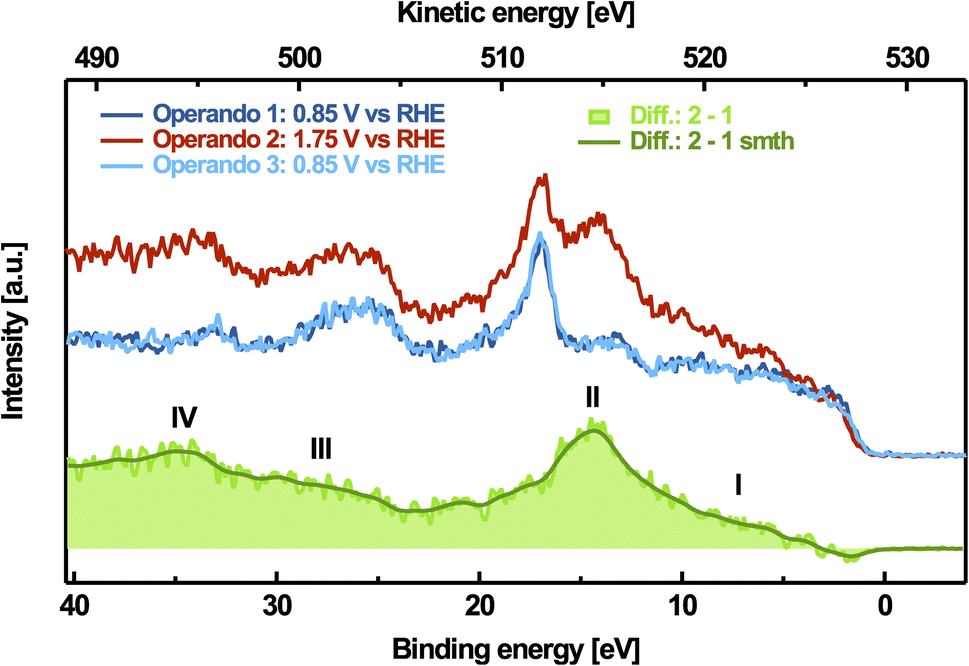 | ||
| Fig. 3 Potential-dependent valence band spectra, measured at an excitation energy of 528.9 eV and resonant spectrum (green) obtained by subtracting the spectrum at the reductive electrode potential from the spectrum at the oxidative electrode potential. The smoothed spectrum was achieved by binomial filtering. | ||
A similar oxygen pre-peak resonance also appears in other materials containing Ni3+ species, for example in NiOx thin-films sputtered with excess oxygen79,80 or in LiNiO2.46,81,82 For both materials, we measured the resonant-PE spectra at the excitation energy of the pre-peak as a reference (see Fig. S12†). In comparison, the difference-resonance PE spectra of the reference materials agree qualitatively well with the operando-measured difference-resonance spectra, reflecting the similar nickel–oxygen hybridization in these systems. This indicates that the oxygen prepeak occurs as a unique feature in different crystal lattice symmetries, being closely related to the oxidation of Ni2+ to Ni2+δ. Therefore, we considered investigating the change in the nickel electronic structure upon oxidation in more detail.
Operando behavior of the Ni-species
To examine changes in the nickel oxidation state with the applied potential, we compare the measured XA-spectra and resonant valence band spectra with the calculated or measured reference spectra. We demonstrate that resonant valence band spectra from references containing Ni2+, Ni3+ and Ni4+ species can be superimposed to reconstruct operando measured spectral differences. Due to the charge redistribution from Ni to O, the oxidized species in the active phase should be better written as (NiO6)2+δ rather than Ni2+δ describing the state of Ni species, which experience one or two holes mainly located at the neighboring oxygen sites. However, for the sake of simplicity, we will use the conventional notation (Ni3+ and Ni4+) here as a short version.Fig. 4 shows potential-dependent measurements of the nickel L3-edge PEY-XA spectra obtained by integrating the valence band region between 0 eV and 40 eV binding energy for each photon energy step. The resonant enhancements in this binding energy range originate from the nickel 2p3d3d spectator Auger and 2p-cb-3d participator Auger electron signals. The nickel L3-edge of octahedral Ni2+ present in the reduced α-Ni(1−x)Fex(OH)2 and in Ni0.75Fe0.25Oy is mainly characterized by two resonances located at a photon energy of Eph ≈ 853.4 eV (feature I) and Eph ≈ 855.3 eV (feature III). These features arise from the 3d8 initial state multiplets.83 During the OER, a broad intensity enhancement of the nickel L3-edge arises in the photon energy range from Eph ≈ 853.7 eV and Eph ≈ 857.7 eV, accompanied by an intensity decrease around feature I. These changes are completely reverted after returning to non-catalytic potentials and can be attributed to the reversible oxidation of a part of the Ni2+ species present under non-catalytic conditions. This redox-process corresponds to the well-known Ni-redox waves43 (compare Fig. 1). The lower panel of Fig. 4 also depicts the calculated reference spectra from Qiao et al. based on a single impurity Anderson model that couples Ni with a 3 eV wide ligand band containing up to one hole.84 From these calculations, it is evident that the absorption spectra of Ni2+, Ni3+ and Ni4+ strongly overlap. It is therefore not trivial to distinguish whether only Ni3+ or Ni4+ is formed exclusively during oxidation, or whether a mixture of both emerges. Indeed, this question is still highly debated and all three scenarios have been proposed. The large nickel K-edge shift observed in operando measurements of electrodeposited iron–nickel hydroxides has been attributed to a formal mean valence of up to 3.8, suggesting that both oxidation states could be present.15,38,42 Other authors found an average oxidation state close to +3 indicating the nickel species to be mainly present in the formal Ni3+-state.28,43 In contrast, operando Mössbauer spectroscopy studies suggested disproportionation into Ni2+ and Ni4+.85,86
 | ||
| Fig. 4 Top: operando PEY nickel L3 XAS spectra of the activated Ni0.75Fe0.25Oy catalyst. Center: difference spectrum of the reduced state (mean-spectrum from before and after the oxidizing step) and the oxidized state. The smoothed curve (in dark green) shown here as a guide to the eye was achieved by binomial filtering of the difference spectrum. Bottom: theoretical Ni3+ and Ni4+ reference spectra, taken from Qiao et al.84 | ||
A comparison of the difference spectrum with the calculated spectra from Qiao et al.84 indicates that the negative signal contribution around feature I corresponds to a decreasing amount of Ni2+-species in the oxidized state. The increase between Eph ≈ 853.7 eV and Eph ≈ 857.7 eV may be consistent with the simultaneous occurrence of Ni3+ and Ni4+. Due to the restricted accuracy of the calculations, a component fit, however, is not trustworthy with calculated references. Furthermore, since both trivalent and tetravalent Ni compounds are unstable in air and in contact with moisture,87 pristine experimental reference spectra are difficult to obtain. Common Ni3+- and Ni4+-reference samples, therefore, always contain Ni2+ species. Thus, to further probe the nickel oxidation state, we examine the resonant PES spectra of the nickel species in more detail.
We measured the resonant valence band spectra at excitation energies corresponding to the maxima of Ni2+ XAS (I: 853.4 eV and III: 855.3 eV), Ni3+ XAS (II: 854.9 eV, according to Qiao et al.84), and Ni4+ XAS (IV: 856.2 eV, according to Qiao et al.84), which capture the Ni 2p3d3d Auger features. Fig. 5 shows for each case the spectral differences obtained by subtracting the resonant valence band spectra measured at 0.85 V vs. RHE from those measured at 1.75 V vs. RHE. The resulting spectral changes upon oxidation are a good starting point for elucidating the oxidation state since the Ni 2p3d3d relaxation channel involves near-valence states.
 | ||
| Fig. 5 Difference spectra between resonant nickel valence bands (VB) measured with 1.75 V vs. RHE applied (OER-regime) and with 0.75 V vs. RHE applied (close to OCP), named electrochemical potential-condition (PC) differences. Also shown: resonant nickel VB spectra (off-resonant contribution subtracted) of different references containing (mainly) Ni2+, Ni3+ and Ni4+, measured on the respective absorption maximum (e.g. 854.9 eV for the Ni3+ reference). These reference spectra are superimposed to fit the difference spectra. The scaling and sign of the reference spectra represent their contribution to the fits. (a) PC-difference spectrum measured at the Ni4+ maximum at 856.2 eV photon energy compared with NiO− and nickel(IV) paraperiodate resonant VB reference spectra used as fitting components. (b) PC-difference spectrum measured at the second Ni2+ maximum at 855.3 eV photon energy together with NiO− and LiNiO2 resonant VB reference spectra. (c) PC-difference spectrum measured at the Ni3+ maximum at 854.9 eV photon energy together with NiO− and LiNiO2 resonant VB reference spectra. (d) PC-difference spectrum measured at the first Ni2+ maximum at 853.4 eV photon energy matching the negative resonant NiO-valence band reference spectrum quite well. Also shown: off-resonant VB calculated by Tanaka et al.88 The black line in (a–d) corresponds to the smoothed PC-difference spectra. The green and yellow lines in (a–d) represent the reference superpositions fitted to the PC-difference spectra. Difference fit (green): Ni3+-reference used for fitting the PC-difference at 854.9 eV and Ni4+-reference used for fitting the PC-difference at 856.2 eV. Difference fit* (yellow): Ni4+-reference used for fitting the PC-difference at 854.9 eV and Ni3+-reference used for fitting the PC-difference at 856.2 eV. (e) operando PEY nickel L3 XAS spectra of the activated Ni0.75Fe0.25Oy catalyst (same as those shown in Fig. 4) with all resonance-differences emphasized. | ||
For feature I at Eph ≈ 853.4 eV, the difference spectrum is negative due to the decrease of the Ni2+ resonance, as confirmed by comparison with experimental data (see Fig. 5 below). At the second absorption maximum at Eph ≈ 855.3 eV (feature III), the decrease in the Ni2+ absorption is overlaid by a much stronger increase of the Ni3+ absorption. A fit of the difference between the resonant valence band spectrum of Ni3+ containing LiNiO2 and that of the Ni2+ reference NiO does reproduce the measured difference well. This also applies for the Ni3+ resonance at Eph ≈ 854.9 eV (feature II). We note that the LiNiO2 reference sample contains some Ni2+, but this is compensated for by the subtraction procedure. Thus, we were able to reproduce the potential dependent change of the Ni4+ resonance at Eph ≈ 856.2 eV (feature IV) by fitting the difference between the resonant Ni2+ and Ni4+ valence band spectra. The Ni4+-spectrum was measured on potassium nickel paraperiodate (K2Ni(H2IO6)2) kept under an inert atmosphere or vacuum. Applying the same fitting routine using the Ni3+ reference instead results in a slightly worse agreement between data and fit (compare Table ST2†). This could be an indication that part of the oxidized species exhibits a Ni4+-like valence. When using the Ni4+ reference, the fit at the Ni3+ resonance deteriorates slightly, which is consistent with the expected dominance of oxidized Ni3+ species. Despite this, our experimental measurements cannot provide unambiguous evidence for the occurrence of Ni4+ species, but the formation of a small fraction of it is at least consistent with the data.
It is noteworthy that all difference resonant valence spectra show a negative contribution at around EB ≈ 0–3 eV, which cannot be compensated for by the difference fits. Similar negative contributions are also present in the difference between the off-resonant valence band spectra of the oxidized and reduced states (see Fig. S13†), as well as in the valence band spectrum at the O1s resonance shown in Fig. 3. According to Tanaka et al., the off-resonant XPS signals of the outer 3d electrons of NiO are expected at binding energies between 0 eV and 3 eV (see Fig. 5).88 However, their intensity is several orders of magnitude lower compared to that of the resonant features.88 Consequently, a decrease of the off-resonant Ni 3d signal due to Ni oxidation would be consistent with the occurring differences, but cannot be considered as an explanation here. It is more likely that the valence band shifts due to inhomogeneous local potentials of the individual components caused by the applied voltage. This could be explained by the same phenomenon that also affects changes in the O 1s peak (see the discussion in Section D of the ESI†).
In conclusion, the electrode potential-dependent Ni L3-edge PEY-XA as well as the Ni 2p3d3d-resonant Auger spectra are consistent with the simultaneous presence of Ni3+ and Ni4+ species in Ni(1−x)FexOOHy under catalytic conditions. More detailed Ni 2p3d3d-resonant Auger spectra hold the potential to separate the spectral contributions of Ni3+ and Ni4+.
Deriving the oxygen p-DOS of the active state
To interpret the observed electronic structure changes with respect to the OER-mechanism, we conflate our results of the oxygen K-edge absorption, oxygen RPES and O 1s XPS. This allows us to assess the role of oxygen species during catalysis. The signal of PEY-XAS is proportional to the empty density of states in the conduction band, while RPES enhances the photoelectron signal originating from the occupied density of states in the valence band. Both spectrum types, therefore, complement each other to yield the partial density of states of the species probed.89,90Combining the oxygen K PEY-XAS and RPES requires us to know the binding energy of the core level states being excited during the initial photoexcitation. The XPS-signal corresponding to these states is covered as a contribution to the O 1s region measured at oxidizing electrode potentials (shown in Fig. S6†). Thus, their binding energy cannot be easily extracted. Following our discussion above and in Section D of the ESI,† the active phase contains additional deprotonated oxidic species compared to the reduced hydroxide phase. We thus assume these to be the oxygen species related to the active phase, which is also consistent with the finding that the γ-phase is almost completely deprotonated.12 As Löyty et al. have shown for electrodeposited iron–nickel hydroxides, the fraction of oxidic O 1s intensity increases and the hydroxide contribution decreases at oxidizing electrode potentials.54 Changes in the oxygen core level binding energy of the catalyst are insignificant in our data, which is consistent with the binding energies of the oxidic species remaining unchanged. We, therefore, argue that the core-level binding energy of the oxygen species in the active phase is approximately the same as that of the oxidic oxygen in Ni0.75Fe0.25Oy, which we determined to be EB ≈ 529.6 eV. This value is similar to the O 1s binding energy of oxidic species in FeOOH, which was reported to be between EB ≈ 529.6 eV and EB ≈ 529.9 eV.91–94
The core-level binding energy calibrated to the Fermi level EF represents the photon energy necessary to (virtually) excite an electron to EF. Thus, the latter can be used to identify the Fermi level with respect to the unoccupied states probed by PEY-XAS. Based on the known Fermi level, we combine the PEY-XA-spectrum of γ-Ni0.75Fe0.25OOHy measured at 1.75 V vs. RHE and the corresponding RESPE-spectrum at 528.9 eV photon energy calibrated against the Fermi level to create the partial-DOS shown in Fig. 6. Here, we focus only on the oxygen-derived density of states, as photoexcitation from O 1s can only occur to oxygen-hybridized states due to dipole selection rules. Since we probe a heterogeneous system, the PEY-XA-spectrum covers contributions from graphene oxide and possibly hydroxide species of the electrolyte along with the contributions of interest corresponding to the active phase. Only the pre-peak can be unequivocally attributed to the active phase, while other contributions being probably similar to the oxidic species in Ni0.75Fe0.25Oy may be present at higher binding energies.
 | ||
| Fig. 6 Experimental oxygen partial density-of-states of the active phase oxidic species (left, catalyst side) related to the energy levels of relevant redox couples (right, electrolyte side). The two spectral components (PEY-XA-spectrum and RESPE-spectrum) are scaled to have the same maximum height. Dark green line: PEY-XAS of the dry Ni0.75Fe0.25Ox-phase, demonstrating its unoccupied states above EF. Light green line: reference PEY-XAS of Ni(OH)2. Light blue line: 1s-cb-2p-participator Auger signal. Gray line: 1s2p2p spectator Auger signal. Shaded dark green area: unoccupied p-DOS. Shaded light blue area: occupied p-DOS. | ||
We added the O K-edge PEY-XA-spectrum of dry Ni0.75Fe0.25Oy to Fig. 6 to illustrate the possible energetic position of the oxide signals. We note that the energy scale and the position of the Fermi level only refer to the oxidic oxygen species of the active phase. The other species contributing to the PEY-XA-spectrum, in general, exhibit different core level binding energies. Therefore, their binding energy scale and Fermi level are shifted relative to the active phase reference given here. As an example, we invoke hydroxide-like species represented by the oxygen K PEY-XA-spectrum of a Ni0.75Fe0.25(OH)2 reference sample plotted as the light-green dashed line in Fig. 6. Although the related Fermi level is at higher energy according to the higher binding energy of the hydroxide core level of EB ≈ 531.3 eV from which it is derived, the relative position of the unoccupied states to the Fermi level is very similar for oxidic and hydroxide species. In contrast to the unoccupied part of the oxygen p-DOS, the occupied part represented by the RESPE-spectrum measured at 528.9 eV photon energy exclusively refers to the oxidic oxygen species of the active phase, since all off-resonant contributions were subtracted. Certainly, the part of the RESPE-spectrum shown in Fig. 6 is composed of the 1s-cb-2p participator and the 1s2p2p spectator Auger signals, as indicated by a fit using two Voigt functions. Only the 1s-cb-2p participator (blue-shaded) reflects the occupied states, as the binding energy of the participator (dashed gray) appears to be shifted according to the band gap and the additional screening contribution of the excited electron in the intermediate state. We note that the exact contribution of the participator indicated by the fit (light blue) is quite uncertain due to the given noise level. It only serves for illustration and in the further discussion, we do not use the energetic position or valence band shape resulting from this fit. The certainty of energetic levels in the derived p-DOS is discussed in detail in Section G of the ESI.†
Based on the position of the Fermi level, we determine the electrode potential of the O2/OH−-redox couple relative to the binding energy scale as developed by Gerischer.95 For this, we assume the Fermi level on the electrolyte side to be equilibrated with the semiconductor side at open circuit potential (OCP), which was determined to be at 0.95 V vs. RHE.95–97 From these assumptions, it directly follows that the Fermi level of the active phase appears shifted by 0.8 V vs. OCP. This defines the energy level of the RHE and the equilibrium potential of the O2/OH−-redox couple, which is 1.229 V vs. RHE. Additionally, the vacuum-level was determined to be about 4.5 eV above the standard hydrogen electrode (SHE).98 Taking into account the Nernstian shift between RHE and SHE, the vacuum level on the electrolyte side can also be added (see Fig. 6).
As already alluded to, the unoccupied states reflected by the pre-peak occurring upon lattice oxidation, and the occupied states reflected by the participator Auger signal, can be clearly attributed to the active phase. An energy gap of about Eg ≈ 1.5 eV can be identified between the two parts of the p-DOS, if the onset of the smoothed resonance spectrum is used as the valence band edge. This is consistent with the calculated band gap values of the active phase,32–34 and is close to the experimental value of 1.8–1.9 eV determined by Carpenter & Corrigan.99 This suggests that our assignment of core level binding energy is fairly realistic.
Most strikingly, the Fermi level is not positioned within this band gap and parts of the unoccupied density of states are located below the Fermi energy. This is not uncommon for oxide material systems, as the gap between the occupied DOS and the DOS derived from oxygen 2p and transition metal (4s,4p)-hybridized states can contain localized covalent defect states derived from oxygen 2p and transition metal 3d states. For example, Schmidt & Schmeißer have identified such localized states in Co70Ni30Ox.90 In our case, the unoccupied density of states below the Fermi level can be rationalized by the non-equilibrium condition caused by the applied electrode potential. Under OCP conditions, a source of electrons is present, and oxidizing processes at the interface will change the surface chemistry and would fill these states,26,31 as reflected by the vanishing oxygen PEY-XAS pre-peak for the lower electrode potentials. As can be seen from the derived Gerischer-diagram shown in Fig. 6, such a process can be a step of the OER, as the level of the O2/OH−-redox couple is positioned above the pre-peak states. This finding does not depend on our choice of calibration corresponding to an upper bound of the energetic position of the unoccupied p-DOS. Consequently, the oxygen-derived states reflected by the pre-peak are suitable acceptor states for the OER. The finding that oxygen evolution starts just after passing the reversible redox potential of the active phase is in agreement with a substantial role that the oxygen holes might play in the OER, as they are only present in the oxidized form of the catalyst. We note that this does not necessarily designate the oxygen species to be the active sites or primary electron acceptors. Highly active sites additionally must provide an ideal orbital overlap with the reactants to form energetically beneficial intermediates.1 Indeed, similar oxygen-derived hole states have been identified in iridium oxide and could be assigned to bridging defect oxygen species participating in the OER. But for NiFe hydroxides, recent 18O-labeling studies have shown that the oxygen species do directly participate in the OER.73,100,101 The OER-reactive centers are probably related to the iron edge- or defect sites or adsorbed iron species.22,25
As already examined, the pre-peak reflects hole states primarily located at the O 2p states occurring as O 2p metal 3d hybridized states in nickel–oxygen compounds containing Ni2+δ. Our results now allow for the first time the correlation of these states with the Fermi level and the identification of their contribution to the band structure of the active phase. Consistent with their position within the covalent gap, we assume these states to be formed upon the next nearest neighbor charge-transfer processes: M 3dn O 2p6 ↔ M 3dn+1 O 2p5.90 Consequently, they are localized at the dominating bulk oxygen species of the oxidized phase, which likely make them also influence the most active edge- and defect sites. Due to their covalent character, these states might cause the additional phonon mode detected by operando Raman spectroscopy, which was previously attributed to Ni–OO− superoxol-type species.40,102 Furthermore, as these charge transfer states are directly related to the oxidized neighboring metal species, and as one oxygen is always coordinated to three individual metal species in an ideal lattice, it would be reasonable that charge-transfer processes promote mutual influence of the oxidation state of neighboring metal species. This would well explain the upshift of the γ-NiOOHy reversible redox potential upon iron doping7,8 and the downshift of the iron reversible oxidation potential in γ-Ni(1−x)FexOOHy compared to that in pure FeOOH,26 underpinned by states of oxidized Fe3+–O species reported for bulk material.53,85,86
Braun et al. observed the formation of oxygen-related hole states on hematite photoanodes upon illumination, which become refilled during the OER.103 This indicates that such states play an important role in catalytic turnover. We argue that the charge-transfer processes would also take place between lattice oxygen species and iron species involved in the OER. Therefore, they potentially promote oxidation of the active sites. It has been observed that the intrinsic, conductivity-corrected turnover frequency of iron-related active sites is higher in FeOOH compared to in mixed Ni–Fe oxyhydroxides.104 Our findings suggest that this synergistic effect between iron and nickel in the active phase can be explained by an oxidizing impact of the oxygen-related charge-transfer states occurring in the vicinity of oxidized Ni species on iron-related active sites. This would also be in accordance with their electron acceptor character. On the other hand, these oxygen-related hole states could also modify the covalency of non-lattice oxygen intermediates on the catalyst surface. Recent studies indicate that the formation of intermediates is accompanied and supported by charge redistribution effects in transition metal OER catalysts.51,52 Consequently, oxyl-like surface-structure motifs exhibiting the demonstrated charge redistribution are potentially involved in catalytic steps like, e.g., the O–O bond formation stabilizing suitable intermediates, which determine the OER kinetics.
Our findings highlight the relevance of charge-redistribution in Ni–Fe catalysts for the OER. Future material design should involve this important property, which depends on the Fe concentration and can additionally be tuned by doping with other transition metal species like Co.105
Conclusions
We have applied resonant photoelectron spectroscopy to gain insight into the electronic structure of γ-Ni(1−x)FexOOHy, which is a state-of-the-art alkaline OER-catalyst. From oxygen core level XPS, the resonant valence band at 528.9 eV photon energy and oxygen K PEY-XAS, we were able to construct the p-DOS of the oxygen-derived species. Based on thais, we have revisited the role of oxygen species in the redox transition and the OER. The active phase contains oxygen-derived charge transfer states, which are involved in the collaborative oxidation of iron and nickel species. These charge transfer states potentially promote the oxidation of iron-related active centers. Consequently, they act as indirect acceptor states for the OER. Thus, these states might be the key to understand the synergistic effect between iron and nickel in γ-Ni(1−x)FexOOHy. Furthermore, the metal–oxygen charge redistribution effects support the formation of oxyl-like surface motifs, which are potentially involved in the catalytic turnover. Additionally, we investigated the nickel oxidation state based on nickel L3 PEY-XAS and the 2p3d3d-resonant Auger signals. While Ni3+ and Ni4+ like species cannot be distinguished from XAS, applying linear combination analysis based on resonant PE spectra is a promising approach to extract insight into the most likely oxidation state/s of the material under realistic working conditions, provided that sufficiently good counting statistics can be achieved.Our study shows that resonant operando photoelectron spectroscopy is a powerful tool for illuminating details of the electronic structure of a catalyst, which are key for the understanding of electrocatalytically active interfaces.
Author contributions
The manuscript was written through contributions of all the authors. All authors have given approval to the final version of the manuscript. A. B., R. S., G. W. and D. H. conceptualized the experiments. G. W. and D. H. prepared the samples and conducted the operando PES experiments. G. W. performed the XRD and AFM measurements. R. W. performed the TEM measurements and associated data analysis. R. S., B. R. C., A. B. and G. W. interpreted the results. G. W. wrote the original manuscript. R. S., B. R. C., A. B., R. W. and G. W. reviewed and edited the manuscript.Conflicts of interest
The authors declare no conflict of interest.Acknowledgements
The authors thank Alexander Steigert for preparing the sputtered samples. In particular, GW, DH and RS thank Dr Juan Velasco-Velez, Dr Rik Mom and Dr Lorenz Falling for sharing their experimental experiences with the graphene-capped ionomer membrane technique. The authors acknowledge Dr Markus Wollgarten for conducting the TEM measurements and Dr Thorsten Schultz for performing the quantitative XPS analysis. We thank Dr Wilson Quevedo for his support in RPES reference sample measurements. The authors also thank the staff of the Helmholtz-Zentrum Berlin for their support during the beamtimes at BESSY II. GW, DH, and RS gratefully acknowledge financial support from the German Research Foundation (DFG) through an Emmy-Noether grant (project SE 2253/3-1). Parts of this work were also funded by the German Federal Ministry of Education and Research (Bundesministerium für Bildung und Forschung, BMBF) under Grant No. 03EW0015B (CatLab).References
- W. T. Hong, M. Risch, K. A. Stoerzinger, A. Grimaud, J. Suntivich and Y. Shao-Horn, Toward the Rational Design of Non-Precious Transition Metal Oxides for Oxygen Electrocatalysis, Energy Environ. Sci., 2015, 8(5), 1404–1427, 10.1039/c4ee03869j.
- E. Fabbri and T. J. Schmidt, Oxygen Evolution Reaction - The Enigma in Water Electrolysis, ACS Catal., 2018, 8(10), 9765–9774, DOI:10.1021/acscatal.8b02712.
- N. Govindarajan, M. T. M. Koper, E. J. Meijer and F. Calle-Vallejo, Outlining the Scaling-Based and Scaling-Free Optimization of Electrocatalysts, ACS Catal., 2019, 9(5), 4218–4225, DOI:10.1021/acscatal.9b00532.
- C. C. L. McCrory, S. Jung, J. C. Peters and T. F. Jaramillo, Benchmarking Heterogeneous Electrocatalysts for the Oxygen Evolution Reaction, J. Am. Chem. Soc., 2013, 135(45), 16977–16987, DOI:10.1021/ja407115p.
- A. Peugeot, C. E. Creissen, D. Karapinar, H. N. Tran, M. Schreiber and M. Fontecave, Benchmarking of Oxygen Evolution Catalysts on Porous Nickel Supports, Joule, 2021, 5(5), 1281–1300, DOI:10.1016/j.joule.2021.03.022.
- F. Dionigi, T. Reier, Z. Pawolek, M. Gliech and P. Strasser, Design Criteria, Operating Conditions, and Nickel-Iron Hydroxide Catalyst Materials for Selective Seawater Electrolysis, ChemSusChem, 2016, 9(9), 962–972, DOI:10.1002/cssc.201501581.
- D. A. Corrigan, The Catalysis of the Oxygen Evolution Reaction by Iron Impurities in Thin Film Nickel Oxide Electrodes, J. Electrochem. Soc., 1987, 134(2), 377, DOI:10.1149/1.2100463.
- L. Trotochaud, S. L. Young, J. K. Ranney and S. W. Boettcher, Nickel-Iron Oxyhydroxide Oxygen-Evolution Electrocatalysts: The Role of Intentional and Incidental Iron Incorporation, J. Am. Chem. Soc., 2014, 136(18), 6744–6753, DOI:10.1021/ja502379c.
- H. Bode, K. Dehmelt and J. Witte, Zur Kenntnis der Nickelhydroxidelektrode I. Über das Nickel(II)-Hydroxidhydrat, Electrochim. Acta, 1966, 11(8), 1079–1087, DOI:10.1016/0013-4686(66)80045-2.
- L. Demourgues-Guerlou, J. J. Braconnier and C. Delmas, Iron-Substituted Nickel Oxyhydroxides and Hydroxides Obtained by Chimie Douce, J. Solid State Chem., 1993, 104(2), 359–367, DOI:10.1006/jssc.1993.1171.
- S. Klaus, Y. Cai, M. W. Louie, L. Trotochaud and A. T. Bell, Effects of Fe Electrolyte Impurities on Ni(OH)2/NiOOH Structure and Oxygen Evolution Activity, J. Phys. Chem. C, 2015, 119(13), 7243–7254, DOI:10.1021/acs.jpcc.5b00105.
- F. Dionigi, Z. Zeng, I. Sinev, T. Merzdorf, S. Deshpande, M. B. Lopez, S. Kunze, I. Zegkinoglou, H. Sarodnik, D. Fan, A. Bergmann, J. Drnec, J. Ferreira de Araújo, M. Gliech and P. Tesc, In-Situ Structure and Catalytic Mechanism of NiFe and CoFe Layered Double Hydroxides during Oxygen Evolution, Nat. Commun., 2020, 11(1), 1–10, DOI:10.1038/s41467-020-16237-1.
- M. Wehrens-Dijksma and P. H. L. Notten, Electrochemical Quartz Microbalance Characterization of Ni(OH)2-Based Thin Film Electrodes, Electrochim. Acta, 2006, 51(18), 3609–3621, DOI:10.1016/j.electacta.2005.10.022.
- H. Trzesniowski, N. Deka, O. van der Heijden, R. Golnak, J. Xiao, M. T. M. Koper, R. Seidel and R. V. Mom, Reversible and Irreversible Cation Intercalation in NiFeOx Oxygen Evolution Catalysts in Alkaline Media, J. Phys. Chem. Lett., 2023, 14(2), 545–551, DOI:10.1021/acs.jpclett.2c03336.
- D. Friebel, M. W. Louie, M. Bajdich, K. E. Sanwald, Y. Cai, A. M. Wise, M. J. Cheng, D. Sokaras, T. C. Weng, R. Alonso-Mori, R. C. Davis, J. R. Bargar, J. K. Nørskov, A. Nilsson and A. T. Bell, Identification of Highly Active Fe Sites in (Ni,Fe)OOH for Electrocatalytic Water Splitting, J. Am. Chem. Soc., 2015, 137(3), 1305–1313, DOI:10.1021/ja511559d.
- L. Trotochaud, J. K. Ranney, K. N. Williams and S. W. Boettcher, Solution-Cast Metal Oxide Thin Film Electrocatalysts for Oxygen Evolution, J. Am. Chem. Soc., 2012, 134(41), 17253–17261, DOI:10.1021/ja307507a.
- I. J. Godwin and M. E. G. Lyons, Enhanced Oxygen Evolution at Hydrous Nickel Oxide Electrodes via Electrochemical Ageing in Alkaline Solution, Electrochem. Commun., 2013, 32, 39–42, DOI:10.1016/j.elecom.2013.03.040.
- A. C. Pebley, E. Decolvenaere, T. M. Pollock and M. J. Gordon, Oxygen Evolution on Fe-Doped NiO Electrocatalysts Deposited: Via Microplasma, Nanoscale, 2017, 9(39), 15070–15082, 10.1039/c7nr04302c.
- X. Su, Y. Wang, J. Zhou, S. Gu, J. Li and S. Zhang, Operando Spectroscopic Identification of Active Sites in NiFe Prussian Blue Analogues as Electrocatalysts: Activation of Oxygen Atoms for Oxygen Evolution Reaction, J. Am. Chem. Soc., 2018, 140(36), 11286–11292, DOI:10.1021/jacs.8b05294.
- M. Al Samarai, A. W. Hahn, A. Beheshti Askari, Y. T. Cui, K. Yamazoe, J. Miyawaki, Y. Harada, O. Rüdiger and S. Debeer, Elucidation of Structure-Activity Correlations in a Nickel Manganese Oxide Oxygen Evolution Reaction Catalyst by Operando Ni L-Edge X-Ray Absorption Spectroscopy and 2p3d Resonant Inelastic X-Ray Scattering, ACS Appl. Mater. Interfaces, 2019, 11(42), 38595–38605, DOI:10.1021/acsami.9b06752.
- A. Bergmann, T. E. Jones, E. Martinez Moreno, D. Teschner, P. Chernev, M. Gliech, T. Reier, H. Dau and P. Strasser, Unified Structural Motifs of the Catalytically Active State of Co(Oxyhydr)Oxides during the Electrochemical Oxygen Evolution Reaction, Nat. Catal., 2018, 1(9), 711–719, DOI:10.1038/s41929-018-0141-2.
- M. B. Stevens, C. D. M. Trang, L. J. Enman, J. Deng and S. W. Boettcher, Reactive Fe-Sites in Ni/Fe (Oxy)Hydroxide Are Responsible for Exceptional Oxygen Electrocatalysis Activity, J. Am. Chem. Soc., 2017, 139(33), 11361–11364, DOI:10.1021/jacs.7b07117.
- J. Deng, M. R. Nellist, M. B. Stevens, C. Dette, Y. Wang and S. W. Boettcher, Morphology Dynamics of Single-Layered Ni(OH)2/NiOOH Nanosheets and Subsequent Fe Incorporation Studied by in Situ Electrochemical Atomic Force Microscopy, Nano Lett., 2017, 17(11), 6922–6926, DOI:10.1021/acs.nanolett.7b03313.
- F. Bao, E. Kemppainen, I. Dorbandt, F. Xi, R. Bors, N. Maticiuc, R. Wenisch, R. Bagacki, C. Schary, U. Michalczik, P. Bogdanoff, I. Lauermann, R. Van De Krol, R. Schlatmann and S. Calnan, Host, Suppressor, and Promoter - The Roles of Ni and Fe on Oxygen Evolution Reaction Activity and Stability of NiFe Alloy Thin Films in Alkaline Media, ACS Catal., 2021, 11, 10537–10552, DOI:10.1021/acscatal.1c01190.
- D. Y. Chung, P. P. Lopes, F. B. D. M. Pedro, H. He, T. Kawaguchi, P. Zapol, H. You, D. Tripkovic, D. Strmcnik, Y. Zhu, S. Seifert, S. Lee, V. R. Stamenkovic and N. M. Markovic, Dynamic Stability of Active Sites in Hydr(Oxy)Oxides for the Oxygen Evolution Reaction, Nat. Energy, 2020, 5(3), 222–230, DOI:10.1038/s41560-020-0576-y.
- H. S. Ahn and A. J. Bard, Surface Interrogation Scanning Electrochemical Microscopy of Ni1−xFexOOH (0<x<0.27) Oxygen Evolving Catalyst: Kinetics of the “Fast” Iron Sites, J. Am. Chem. Soc., 2016, 138(1), 313–318, DOI:10.1021/jacs.5b10977.
- B. M. Hunter, N. B. Thompson, A. M. Müller, G. R. Rossman, M. G. Hill, J. R. Winkler and H. B. Gray, Trapping an Iron(VI) Water-Splitting Intermediate in Nonaqueous Media, Joule, 2018, 2(4), 747–763, DOI:10.1016/j.joule.2018.01.008.
- M. Görlin, P. Chernev, J. Ferreira de Araújo, T. Reier, S. Dresp, B. Paul, R. Krähnert, H. Dau and P. Strasser, Oxygen Evolution Reaction Dynamics, Faradaic Charge Efficiency, and the Active Metal Redox States of Ni-Fe Oxide Water Splitting Electrocatalysts, J. Am. Chem. Soc., 2016, 138(17), 5603–5614, DOI:10.1021/jacs.6b00332.
- M. Gorlin, J. Ferreira de Araújo, H. Schmies, D. Bernsmeier, S. Dresp, M. Gliech, Z. Jusys, P. Chernev, R. Kraehnert, H. Dau and P. Strasser, Tracking Catalyst Redox States and Reaction Dynamics in Ni-Fe Oxyhydroxide Oxygen Evolution Reaction Electrocatalysts: The Role of Catalyst Support and Electrolyte PH, J. Am. Chem. Soc., 2017, 139(5), 2070–2082, DOI:10.1021/jacs.6b12250.
- M. Vandichel, M. Busch and K. Laasonen, Oxygen Evolution on Metal-Oxy-Hydroxides: Beneficial Role of Mixing Fe, Co, Ni Explained via Bifunctional Edge/Acceptor Route, ChemCatChem, 2020, 12(5), 1436–1442, DOI:10.1002/cctc.201901951.
- L. Francàs, S. Corby, S. Selim, D. Lee, C. A. Mesa, R. Godin, E. Pastor, I. E. L. Stephens, K. S. Choi and J. R. Durrant, Spectroelectrochemical Study of Water Oxidation on Nickel and Iron Oxyhydroxide Electrocatalysts, Nat. Commun., 2019, 10(1), 5208, DOI:10.1038/s41467-019-13061-0.
- Z. K. Goldsmith, A. K. Harshan, J. B. Gerken, M. Vörös, G. Galli, S. S. Stahl and S. Hammes-Schiffer, Characterization of NiFe Oxyhydroxide Electrocatalysts by Integrated Electronic Structure Calculations and Spectroelectrochemistry, Proc. Natl. Acad. Sci. U. S. A., 2017, 114(12), 3050–3055, DOI:10.1073/pnas.1702081114.
- J. C. Conesa, Electronic Structure of the (Undoped and Fe-Doped) NiOOHO2 Evolution Electrocatalyst, J. Phys. Chem. C, 2016, 120(34), 18999–19010, DOI:10.1021/acs.jpcc.6b06100.
- K. Dhaka and M. C. Toroker, Revealing the Conducting Character of the β-NiOOH Catalyst through Defect Chemistry, J. Phys. Chem. C, 2019, 123(31), 18895–18904, DOI:10.1021/acs.jpcc.9b01750.
- J. Desilvestro, D. A. Corrigan and M. J. Weaver, Characterization of Redox States of Nickel Hydroxide Film Electrodes By, J. Electrochem. Soc., 1988, 135(4), 885–892 CrossRef CAS.
- L. Demourgues-Guerlou, L. Fournès and C. Delmas, On the Iron Oxidation State in the Iron-Substituted γ Nickel Oxyhydroxides, J. Solid State Chem., 1995, 114(1), 6–14, DOI:10.1006/jssc.1995.1002.
- M. Balasubramanian, C. A. Melendres and S. Mini, X-Ray Absorption Spectroscopy Studies of the Local Atomic and Electronic Structure of Iron Incorporated into Electrodeposited Hydrous Nickel Oxide Films, J. Phys. Chem. B, 2000, 104(18), 4300–4306, DOI:10.1021/jp9921710.
- W. E. O'Grady, K. I. Pandya, K. E. Swider and D. A. Corrigan, In Situ X-Ray Absorption Near-Edge Structure Evidence for Quadrivalent Nickel in Nickel Battery Electrodes, J. Electrochem. Soc., 1996, 143(5), 1613–1617, DOI:10.1149/1.1836687.
- D. K. Bediako, B. Lassalle-Kaiser, Y. Surendranath, J. Yano, V. K. Yachandra and D. G. Nocera, Structure-Activity Correlations in a Nickel-Borate Oxygen Evolution Catalyst, J. Am. Chem. Soc., 2012, 134(15), 6801–6809, DOI:10.1021/ja301018q.
- B. J. Trzesniewski, O. Diaz-Morales, D. A. Vermaas, A. Longo, W. Bras, M. T. M. Koper and W. A. Smith, In Situ Observation of Active Oxygen Species in Fe-Containing Ni-Based Oxygen Evolution Catalysts: The Effect of pH on Electrochemical Activity, J. Am. Chem. Soc., 2015, 137(48), 15112–15121, DOI:10.1021/jacs.5b06814.
- M. Görlin, P. Chernev, P. Paciok, C. W. Tai, J. Ferreira de Araújo, T. Reier, M. Heggen, R. Dunin-Borkowski, P. Strasser and H. Dau, Formation of Unexpectedly Active Ni-Fe Oxygen Evolution Electrocatalysts by Physically Mixing Ni and Fe Oxyhydroxides, Chem. Commun., 2019, 55(6), 818–821, 10.1039/c8cc06410e.
- M. Görlin, J. H. Stenlid, S. Koroidov, H. Y. Wang, M. Börner, M. Shipilin, A. Kalinko, V. Murzin, O. V. Safonova, M. Nachtegaal, A. Uheida, J. Dutta, M. Bauer, A. Nilsson and O. Diaz-Morales, Key Activity Descriptors of Nickel-Iron Oxygen Evolution Electrocatalysts in the Presence of Alkali Metal Cations, Nat. Commun., 2020, 11(1), 6181, DOI:10.1038/s41467-020-19729-2.
- D. González-Flores, K. Klingan, P. Chernev, S. Loos, M. R. Mohammadi, C. Pasquini, P. Kubella, I. Zaharieva, R. D. L. Smith and H. Dau, Nickel-Iron Catalysts for Electrochemical Water Oxidation-Redox Synergism Investigated by: In Situ X-Ray Spectroscopy with Millisecond Time Resolution, Sustainable Energy Fuels, 2018, 2(9), 1986–1994, 10.1039/c8se00114f.
- N. Li, D. K. Bediako, R. G. Hadt, D. Hayes, T. J. Kempa, F. Von Cube, D. C. Bell, L. X. Chen and D. G. Nocera, Influence of Iron Doping on Tetravalent Nickel Content in Catalytic Oxygen Evolving Films, Proc. Natl. Acad. Sci. U. S. A., 2017, 114(7), 1486–1491, DOI:10.1073/pnas.1620787114.
- J. Zhang, J. R. Winkler, H. B. Gray and B. M. Hunter, Mechanism of Nickel-Iron Water Oxidation Electrocatalysts, Energy Fuels, 2021, 35(23), 19164–19169, DOI:10.1021/acs.energyfuels.1c02674.
- P. Kuiper, G. Kruizinga, J. Ghijsen, G. A. Sawatzky and H. Verweij, Character of Holes in LixNi1−xO and Their Magnetic Behavior, Phys. Rev. Lett., 1989, 62(10), 1214, DOI:10.1103/physrevlett.62.1214.
- J. van Elp, B. G. Searle, G. A. Sawatzky and M. Sacchi, Ligand Hole Induced Symmetry Mixing of d8 States in LixNi1−xO, as Observed in Ni 2p X-Ray Absorption Spectroscopy, Solid State Commun., 1991, 80(1), 67–71, DOI:10.1016/0038-1098(91)90600-Z.
- K. Foyevtsova, I. Elfimov, J. Rottler and G. A. Sawatzky, LiNiO2 as a High-Entropy Charge- and Bond-Disproportionated Glass, Phys. Rev. B, 2019, 100(16), 1–7, DOI:10.1103/PhysRevB.100.165104.
- V. Pfeifer, T. E. Jones, V. Vélez, J. Juan, C. Massué, R. Arrigo, D. Teschner, F. Girgsdies, M. Scherzer, M. T. Greiner, J. Allan, M. Hashagen, G. Weinberg, S. Piccinin, M. Hävecker and R. Knop-Ge, The Electronic Structure of Iridium and Its Oxides, Surf. Interface Anal., 2016, 48(5), 261–273, DOI:10.1002/sia.5895.
- V. Pfeifer, T. E. Jones, V. Vélez, J. Juan, R. Arrigo, S. Piccinin, M. Hävecker, A. Knop-Gericke and R. Schlögl, In Situ Observation of Reactive Oxygen Species Forming on Oxygen-Evolving Iridium Surfaces, Chem. Sci., 2017, 8(3), 2143–2149, 10.1039/c6sc04622c.
- H. N. Nong, L. J. Falling, A. Bergmann, M. Klingenhof, H. P. Tran, C. Spöri, R. Mom, J. Timoshenko, G. Zichittella, A. Knop-Gericke, S. Piccinin, J. Pérez-Ramírez, B. Roldan Cuenya, R. Schlögl, P. Strasser, D. Teschner and T. E. Jones, Key Role of Chemistry versus Bias in Electrocatalytic Oxygen Evolution, Nature, 2020, 587(7834), 408–413, DOI:10.1038/s41586-020-2908-2.
- F. T. Haase, A. Bergmann, T. E. Jones, J. Timoshenko, A. Herzog, H. S. Jeon, C. Rettenmaier and B. Roldan Cuenya, Size Effects and Active State Formation of Cobalt Oxide Nanoparticles during the Oxygen Evolution Reaction, Nat. Energy, 2022, 7(8), 765–773, DOI:10.1038/s41560-022-01083-w.
- J. Y. C. Chen, L. Dang, H. Liang, W. Bi, J. B. Gerken, S. Jin, E. E. Alp and S. S. Stahl, Operando Analysis of NiFe and Fe Oxyhydroxide Electrocatalysts for Water Oxidation: Detection of Fe4+ by Mössbauer Spectroscopy, J. Am. Chem. Soc., 2015, 137(48), 15090–15093, DOI:10.1021/jacs.5b10699.
- H. Ali-Löytty, M. W. Louie, M. R. Singh, L. Li, C. Sanchez, G. Hernan, H. Ogasawara, E. J. Crumlin, Z. Liu, A. T. Bell, A. Nilsson and D. Friebel, Ambient-Pressure XPS Study of a Ni-Fe Electrocatalyst for the Oxygen Evolution Reaction, J. Phys. Chem. C, 2016, 120(4), 2247–2253, DOI:10.1021/acs.jpcc.5b10931.
- R. Seidel, B. Winter and S. E. Bradforth, Valence Electronic Structure of Aqueous Solutions: Insights from Photoelectron Spectroscopy, Annu. Rev. Phys. Chem., 2016, 67(1), 283–305, DOI:10.1146/annurev-physchem-040513-103715.
- H. Ali, R. Seidel, M. N. Pohl and B. Winter, Molecular Species Forming at the α-Fe2O3 Nanoparticle-Aqueous Solution Interface, Chem. Sci., 2018, 9(19), 4511–4523, 10.1039/c7sc05156e.
- H. Ali, R. Seidel, A. Bergmann and B. Winter, Electronic Structure of Aqueous-Phase Anatase Titanium Dioxide Nanoparticles Probed by Liquid Jet Photoelectron Spectroscopy, J. Mater. Chem. A, 2019, 7(12), 6665–6675, 10.1039/c8ta09414d.
- H. Ali, R. Golnak, R. Seidel, B. Winter and J. Xiao, In Situ X-Ray Spectroscopy of the Electric Double Layer around TiO2 Nanoparticles Dispersed in Aqueous Solution: Implications for H2 Generation, ACS Appl. Nano Mater., 2020, 3, 264–273, DOI:10.1021/acsanm.9b01939.
- D. Hein, G. Wartner, A. Bergmann, M. Bernal, B. Roldan Cuenya and R. Seidel, Reversible Water-Induced Phase Changes of Cobalt Oxide Nanoparticles, ACS Nano, 2020, 14(11), 15450–15457, DOI:10.1021/acsnano.0c06066.
- R. Mom, L. Frevel, J. J. Velasco-Vélez, M. Plodinec, A. Knop-Gericke and R. Schlögl, The Oxidation of Platinum under Wet Conditions Observed by Electrochemical X-Ray Photoelectron Spectroscopy, J. Am. Chem. Soc., 2019, 141(16), 6537–6544, DOI:10.1021/jacs.8b12284.
- L. J. Frevel, R. Mom, J. J. Velasco-Vélez, M. Plodinec, A. Knop-Gericke, R. Schlögl and T. E. Jones, In Situ X-Ray Spectroscopy of the Electrochemical Development of Iridium Nanoparticles in Confined Electrolyte, J. Phys. Chem. C, 2019, 123(14), 9146–9152, DOI:10.1021/acs.jpcc.9b00731.
- L. J. Falling, R. V. Mom, S. Diaz, E. Luis, S. Nakhaie, E. Stotz, D. Ivanov, M. Hävecker, T. Lunkenbein, A. Knop-Gericke, R. Schlögl and J. J. Velasco-Vélez, Graphene-Capped Liquid Thin Films for Electrochemical Operando X-Ray Spectroscopy and Scanning Electron Microscopy, ACS Appl. Mater. Interfaces, 2020, 12(33), 37680–37692, DOI:10.1021/acsami.0c08379.
- J. J. Velasco-Velez, R. V. Mom, L.-E. Sandoval-Diaz, L. J. Falling, C.-H. Chuang, D. Gao, T. E. Jones, Q. Zhu, R. Arrigo, B. Roldan Cuenya, A. Knop-Gericke, T. Lunkenbein and R. Schlögl, Revealing the Active Phase of Copper during the Electroreduction of CO2 in Aqueous Electrolyte by Correlating in Situ X-Ray Spectroscopy and in Situ Electron Microscopy, ACS Energy Lett., 2020, 5(6), 2106–2111, DOI:10.1021/acsenergylett.0c00802.
- I. Lauermann and A. Steigert, CISSY: A Station for Preparation and Surface/Interface Analysis of Thin Film Materials and Devices, Journal of large-scale research facilities, 2016, 2, 4–7, DOI:10.17815/jlsrf-2-84.
- J. W. Suk, A. Kitt, C. W. Magnuson, Y. Hao, S. Ahmed, J. An, A. K. Swan, B. B. Goldberg and R. S. Ruoff, Transfer of CVD-Grown Monolayer Graphene onto Arbitrary Substrates, ACS Nano, 2011, 5(9), 6916–6924, DOI:10.1021/nn201207c.
- A. Kolmakov, D. A. Dikin, L. J. Cote, J. Huang, M. K. Abyaneh, M. Amati, L. Gregoratti, S. Günther and M. Kiskinova, Graphene Oxide Windows for in Situ Environmental Cell Photoelectron Spectroscopy, Nat. Nanotechnol., 2011, 6(10), 651–657, DOI:10.1038/nnano.2011.130.
- D. Nečas and P. G. Klapetek, An Open-Source Software for SPM Data Analysis, Cent. Eur. J. Phys., 2012, 10(1), 181–188, DOI:10.2478/s11534-011-0096-2.
- C. A. Schneider, W. S. Rasband and K. W. Eliceiri, NIH Image to ImageJ: 25 Years of Image Analysis, Nat. Methods, 2012, 9(7), 671–675, DOI:10.1038/nmeth.2089.
- T. Kachel, The Plane Grating Monochromator Beamline U49-2 PGM-1 at BESSY II, Journal of large-scale research facilities, 2016, 2, 2–5, DOI:10.17815/jlsrf-2-75.
- R. Seidel, M. N. Pohl, H. Ali, B. Winter and E. F. Aziz, Advances in Liquid Phase Soft X-Ray Photoemission Spectroscopy: A New Experimental Setup at BESSY II, Rev. Sci. Instrum., 2017, 88, 073107, DOI:10.1063/1.4990797.
- A. Knop-Gericke, V. Pfeifer, J. J. Velasco-Velez, T. Jones, R. Arrigo, M. Hävecker and R. Schlögl, In Situ X-Ray Photoelectron Spectroscopy of Electrochemically Active Solid-Gas and Solid-Liquid Interfaces, J. Electron Spectrosc. Relat. Phenom., 2017, 221, 10–17, DOI:10.1016/j.elspec.2017.03.010.
- D. F. Abbott, E. Fabbri, M. Borlaf, F. Bozza, R. Schäublin, M. Nachtegaal, T. Graule and T. J. Schmidt, Operando, X-Ray Absorption Investigations into the Role of Fe in the Electrochemical Stability and Oxygen Evolution Activity of Ni1−xFexOy Nanoparticles, J. Mater. Chem. A, 2018, 6(47), 24534–24549, 10.1039/c8ta09336a.
- C. Roy, B. Sebok, S. B. Scott, E. M. Fiordaliso, J. E. Sørensen, A. Bodin, D. B. Trimarco, C. D. Damsgaard, P. C. K. Vesborg, O. Hansen, I. E. L. Stephens, J. Kibsgaard and I. Chorkendorff, Impact of Nanoparticle Size and Lattice Oxygen on Water Oxidation on NiFeOxHy, Nat. Catal., 2018, 1(11), 820–829, DOI:10.1038/s41929-018-0162-x.
- F. M. F. de Groot, M. Grioni, J. C. Fuggle, J. Ghijsen, G. A. Sawatzky and H. Petersen, Oxygen 1s X-Ray-Absorption Edges of Transition-Metal Oxides, Phys. Rev. B: Condens. Matter Mater. Phys., 1989, 40(8), 5715–5723, DOI:10.1103/PhysRevB.40.5715.
- Y. Nishina and S. Eigler, Chemical and Electrochemical Synthesis of Graphene Oxide - a Generalized View, Nanoscale, 2020, 12(24), 12731–12740, 10.1039/d0nr02164d.
- M. Yoshida, Y. Mitsutomi, T. Mineo, M. Nagasaka, H. Yuzawa, N. Kosugi and H. Kondoh, Direct Observation of Active Nickel Oxide Cluster in Nickel-Borate Electrocatalyst for Water Oxidation by in Situ O K-Edge X-Ray Absorption Spectroscopy, J. Phys. Chem. C, 2015, 119(33), 19279–19286, DOI:10.1021/acs.jpcc.5b06102.
- D. Drevon, M. Görlin, P. Chernev, L. Xi, H. Dau and K. M. Lange, Uncovering The Role of Oxygen in Ni-Fe(OxHy) Electrocatalysts Using in Situ Soft X-Ray Absorption Spectroscopy during the Oxygen Evolution Reaction, Sci. Rep., 2019, 9(1), 1–11, DOI:10.1038/s41598-018-37307-x.
- S. Hüfner, Photoelectron Spectroscopy, Springer-Verlag Berlin Heidelberg GmbH, 2003 Search PubMed.
- D.-Y. Cho, S. J. Song, U. K. Kim, K. M. Kim, H.-K. Lee and C. S. Hwang, Spectroscopic Investigation of the Hole States in Ni-Deficient NiO Films, J. Mater. Chem. C, 2013, 1(28), 4334–4338, 10.1039/c3tc30687a.
- A. Gutiérrez, G. Domínguez-Cañizares, S. Krause, D. Díaz-Fernández and L. Soriano, Thermal Induced Depletion of Cationic Vacancies in NiO Thin Films Evidenced by X-Ray Absorption Spectroscopy at the O 1s Threshold, J. Vac. Sci. Technol., A, 2020, 38(3), 033209, DOI:10.1116/6.0000080.
- P. Kuiper and B. I. Dunlap, The Σ* Absorption Peak at the Oxygen 1s Edge of O2: Exchange Splitting, Ultrafast Dissociation, and Atomiclike Auger Spectra, J. Chem. Phys., 1994, 100(6), 4087–4092, DOI:10.1063/1.466346.
- Y. Uchimoto, H. Sawada and T. Yao, Changes in Electronic Structure by Li Ion Deintercalation in LiNiO2 from Nickel L-Edge and O K-Edge XANES, J. Power Sources, 2001, 97–98, 326–327, DOI:10.1016/S0378-7753(01)00624-3.
- H. Ishii, Y. Ishiwata, R. Eguchi, Y. Harada, M. Watanabe, A. Chainani and S. Shin, Resonant Soft X-Ray Emission Spectroscopy of NiO across the Ni L2,3 Thresholds, J. Phys. Soc. Jpn., 2001, 70(6), 1813–1816, DOI:10.1143/JPSJ.70.1813.
- R. Qiao, L. A. Wray, J. H. Kim, N. P. W. Pieczonka, S. J. Harris and W. Yang, Direct Experimental Probe of the Ni(II)/Ni(III)/Ni(IV) Redox Evolution in LiNi0.5Mn1.5O4 Electrodes, J. Phys. Chem. C, 2015, 119(49), 27228–27233, DOI:10.1021/acs.jpcc.5b07479.
- L. Guerlou-Demourgues, L. Fournes and C. Delmas, In Situ 57Fe Mössbauer Spectroscopy Study of the Electrochemical Behavior of an Iron-Substituted Nickel Hydroxide Electrode, J. Electrochem. Soc., 1996, 143(10), 3083–3088, DOI:10.1149/1.1837168.
- P. Axmann and O. Glemser, Nickel Hydroxide as a Matrix for Unusual Valencies: The Electrochemical Behaviour of Metal(III)-Ion-Substituted Nickel Hydroxides of the Pyroaurite Type, J. Alloys Compd., 1997, 246(1–2), 232–241, DOI:10.1016/S0925-8388(96)02479-6.
- M. Bianchini, M. Roca-Ayats, P. Hartmann, T. Brezesinski and J. Janek, Hin Und Zurück - Die Entwicklung von LiNiO2 Als Kathodenaktivmaterial, Angew. Chemie, 2019, 131(31), 10542–10569, DOI:10.1002/ange.201812Angew.Chem.472.
- A. Tanaka and T. Jo, Resonant 3d, 3p and 3s Photoemission in Transition Metal Oxides Predicted at 2p Threshold, J. Phys. Soc. Jpn., 1994, 63(7), 2788–2807, DOI:10.1143/JPSJ.63.2788.
- M. H. Richter, W. H. Cheng, E. J. Crumlin, W. S. Drisdell, H. A. Atwater, D. Schmeißer, N. S. Lewis and B. S. Brunschwig, X-Ray Photoelectron Spectroscopy and Resonant X-Ray Spectroscopy Investigations of Interactions between Thin Metal Catalyst Films and Amorphous Titanium Dioxide Photoelectrode Protection Layers, Chem. Mater., 2021, 33(4), 1265–1275, DOI:10.1021/acs.chemmater.0c04043.
- S. Schmidt and D. Schmeißer, Electronic Structure of Cobalt-Nickel Mixed Oxides, Solid State Ionics, 2012, 225, 737–741, DOI:10.1016/j.ssi.2012.06.009.
- R. G. Jonasson, R. R. Martin, M. E. Giuliacci and K. Tazaki, Surface Reactions of Goethite with Phosphate, J. Chem. Soc., Faraday Trans. 1, 1988, 84(7), 2311–2315, 10.1039/F19888402311.
- A. N. Mansour and R. A. Brizzolara, Characterization of the Surface of α-FeOOH Powder by XPS, Surf. Sci. Spectra, 1996, 4(4), 357–362, DOI:10.1116/1.1247825.
- Z. Sun, X. Feng and W. Hou, Morphology-Controlled Synthesis of α-FeOOH and Its Derivatives, Nanotechnology, 2007, 18(45), 455607, DOI:10.1088/0957-4484/18/45/455607.
- A. A. Jelle, M. Hmadeh, P. G. O'Brien, D. D. Perovic and G. A. Ozin, Photocatalytic Properties of All Four Polymorphs of Nanostructured Iron Oxyhydroxides, ChemNanoMat, 2016, 2(11), 1047–1054, DOI:10.1002/cnma.201600251.
- H. Gerischer, Über den Ablauf von Redoxreaktionen an Metallen und an Halbleitern III. Halbleiterelektroden, Zeitschrift für Phys. Chemie, 1961, 27, 48–79, DOI:10.1524/zpch.1961.27.1_2.048.
- H. Gerischer and W. Ekardt, Fermi Levels in Electrolytes and the Absolute Scale of Redox Potentials, Appl. Phys. Lett., 1983, 43(4), 393–395, DOI:10.1063/1.94356.
- H. Reiss, The Fermi Level and the Redox Potential, J. Phys. Chem., 1985, 89(18), 3783–3791, DOI:10.1021/j100264a005.
- F. Lohmann, Fermi-Niveau und Flachbandpotential von Molekülkristallen aromatischer Kohlenwasserstoffe, Z. Naturforsch., A: Astrophys., Phys. Phys. Chem., 1967, 22(5), 843–844, DOI:10.1515/zna-1967-0541.
- M. K. Carpenter and D. A. Corrigan, Photoelectrochemistry of Nickel Hydroxide Thin Films, J. Electrochem. Soc., 1989, 136(4), 1022–1026, DOI:10.1149/1.2096777.
- S. Lee, K. Banjac, M. Lingenfelder and X. Hu, Oxygen Isotope Labeling Experiments Reveal Different Reaction Sites for the Oxygen Evolution Reaction on Nickel and Nickel Iron Oxides, Angew. Chem., Int. Ed., 2019, 58(30), 10295–10299, DOI:10.1002/anie.201903200.
- S. Lee, L. Bai and X. Hu, Deciphering Iron-Dependent Activity in Oxygen Evolution Catalyzed by Nickel-Iron Layered Double Hydroxide, Angew. Chem., Int. Ed., 2020, 59(21), 8072–8077, DOI:10.1002/anie.201915803.
- O. Diaz-Morales, D. Ferrus-Suspedra and M. T. M. Koper, The Importance of Nickel Oxyhydroxide Deprotonation on Its Activity towards Electrochemical Water Oxidation, Chem. Sci., 2016, 7(4), 2639–2645, 10.1039/c5sc04486c.
- A. Braun, K. Sivula, D. K. Bora, J. Zhu, L. Zhang, M. Grätzel, J. Guo and E. C. Constable, Direct Observation of Two Electron Holes in a Hematite Photoanode during Photoelectrochemical Water Splitting, J. Phys. Chem. C, 2012, 116(32), 16870–16875, DOI:10.1021/jp304254k.
- S. Zou, M. S. Burke, M. G. Kast, J. Fan, N. Danilovic and S. W. Boettcher, Fe (Oxy)Hydroxide Oxygen Evolution Reaction Electrocatalysis: Intrinsic Activity and the Roles of Electrical Conductivity, Substrate, and Dissolution, Chem. Mater., 2015, 27(23), 8011–8020, DOI:10.1021/acs.chemmater.5b03404.
- M. K. Bates, Q. Jia, H. Doan, W. Liang and S. Mukerjee, Charge-Transfer Effects in Ni-Fe and Ni-Fe-Co Mixed-Metal Oxides for the Alkaline Oxygen Evolution Reaction, ACS Catal., 2016, 6(1), 155–161, DOI:10.1021/acscatal.5b01481.
Footnote |
| † Electronic supplementary information (ESI) available: Morphology and crystallite size, oxygen 1s XPS water gas subtraction, graphene characterization, spectroscopic contributions of carbon-species and graphene oxidation, oxygen K XAS and pre-peak resonance of reference materials, oxygen formation, parameter values of the resonant Ni-valence band difference fits, potential dependency of the off-resonant valence band, certainty of the energetic levels in the derived oxygen p-DOS, and influence of radiation damage. See DOI: https://doi.org/10.1039/d2ta08961k |
| This journal is © The Royal Society of Chemistry 2023 |