 Open Access Article
Highly proton conductive and stable sulfonated poly(arylene-alkane) for fuel cells with performance over 2.46 W cm−2†
Wenhao
Li
abc,
Run
Zhang
bc,
Xiaoyu
Zhao
bc,
Zhouying
Yue
b,
Huidong
Qian
 *bc and
Hui
Yang
 *ab
*ab
aSchool of Physical Science and Technology, ShanghaiTech University, Shanghai 201210, China
bShanghai Advanced Research Institute, Chinese Academy of Sciences, Shanghai 201210, China. E-mail: qianhd@sari.ac.cn; yangh@sari.ac.cn
cUniversity of Chinese Academy of Sciences, Beijing 100049, China
First published on 25th January 2023
Abstract
Polyaromatic proton exchange membranes (PEMs) are considered an ideal alternative to perfluorosulfonic acid (PFSA) membranes because of their low-cost and intrinsic low permeability. However, a PEM fuel cell's performance and stability with aromatic PEMs are lower than those with PFSA membranes due to the insufficient proton conductivity and chemical degradation. Herein, we highlight the synthesis of sulfonated poly(arylene-alkane) (Poly(FLx-BPy)-SO3H) PEMs with a comb-like structure design of the combination of rigid ether-free backbones and locally double sulfohexyl flexible side-chains, which would enable high proton conductivity and good chemical stability. Such a comb-like structure leads to the well-developed microphase separation morphology and dense ion clusters or continuous ion channels within the membranes, thus ensuring the highest proton conductivity of 0.115 S cm−1 at 25 °C and favorable anti-oxidative stability. Importantly, a H2/O2 PEM fuel cell (PEMFC) using an identical Poly(FL50-BP50)-SO3H membrane and ionomer presents an outstanding power density over 2.46 W cm−2 under 2 bar backpressure at 80 °C, which is one of the best-reported results. In the meantime, the PEMFC with this membrane exhibits an excellent stability owing to the ether-free structure and high interfacial compatibility. The comb-like design, ether-free structure and identical membrane and ionomer provide insight into the development of advanced polyaromatic PEMs.
Introduction
Commercially available PFSA membranes such as Nafion membranes have been the benchmark over the last few decades because of their outstanding proton conductivity, mechanical properties, desired oxidative stability, etc.1,2 Nevertheless, the high cost, environmental harm, gas crossover and complex preparation processes prevent their large-scale commercialization.3 Hence, it has become a new focus to prepare low-cost hydrocarbon-based PEMs. A large number of aromatic polymers, such as poly(arylene ether ketone),4–6 poly(arylene ether sulfone),7,8 poly(phenylene),9 polyimide,10 poly(benzimidazole)11–13 and poly(arylene ether)14 have been prepared as alternatives to PFSA membranes. Nevertheless, there are still few low-cost aromatic PEMs having high-performance and durability comparable to Nafion membranes due to their low ion exchange capacity (IEC), obscure microphase separation, chemical degradation15 and incompatibility with PEMs and ionomers. Although increasing the value of IEC can effectively improve the fuel cell performance, the formation of a distinct microphase separation morphology is viewed as a more important approach by numerous researchers because of the balance between the proton conductivity and mechanical properties.16–19 And from the view of molecular design, a flexible sulfonated side-chain structure can facilitate the formation of a well-developed microphase separation morphology as well as construct a continuous hydrophilic ionic pathway, thus resulting in high performance and acceptable swelling.20–22 Furthermore, ether-free backbones are considered a desired choice for prohibiting attack of hydroxyl radicals on ether bonds, which provides the fundamental support for achieving excellent membrane electrode assembly (MEA) durability.23,24 Therefore, a series of synthetic methods used for the preparation of ether-free polymers, such as metal-catalyzed coupling reactions,9 Diels–Alder polymerization25 and superacid-catalyzed Friedel–Crafts polyhydroxyalkylation,26–30 provide a significant platform for designing chemically stable ion exchange membranes.Among these ether-free polyaromatic backbones, poly(arylene-alkane)s are a class of linear polymers prepared by efficient superacid-catalyzed Friedel–Crafts hydroxyalkylation. However, most poly(arylene-alkane)s are studied as anion exchange membranes (AEMs) due to the lack of sulfonation methodology.31–34 Facile and efficient sulfonation of poly(phenyl-alkane)s remains a great challenge. In 2020, Pagels et al.23 presented an effective and simple method of converting an alkyl halide functionality, a common precursor of AEMs,35 to a sulfonate group. The Br– of bromoalkyl side chains was replaced by nucleophilic substitution with potassium thioacetate (KSAc), and then the thioacetate groups were converted to sulfonate groups using m-chloroperoxybenzoic acid (mCPBA) as the oxidant. This approach makes it possible to apply many ether-free polymers bearing a haloalkyl side chain to PEMs and provides inspiration for our work.
Besides, the compatibility of the membrane and ionomer with identical chemical structures plays a key role in boosting the performance and durability of MEAs, which can depress the charge transfer barrier and achieve high miscibility.36 For example, Pu et al.37 used a sulfonated poly(arylene ether ketone) material containing symmetrical tetramethyl groups (SPAEK-TM) as a membrane and ionomer to improve interfacial compatibility between PEMs and catalyst layers, which exhibited a higher power density compared to the Nafion ionomer in a direct methanol fuel cell and H2/air fuel cell. Generally, ionomers are expected to dissolve in low-boiling-point protic solvents to avert adsorption of solvent residues on the catalyst surface, which can cover the electrochemically active site. However, many sulfonated aromatic polymers have a poor solubility in a mixture of water and alcohols, which limits their application in ionomers.
To date, a few researchers have studied fluorene as a backbone for ether-free AEMs due to its superior water vapor permeability and depressed the phenyl adsorption effect.38,39 Yang et al.39 introduced a series of poly[(fluorene alkylene)-co-(biphenyl alkylene)] (PFBA) AEMs, where a H2/O2 anion exchange membrane fuel cell (AEMFC) achieved a peak power density (PPD) of 0.559 W cm−2. Chen et al.33 reported an AEMFC based on poly(fluorenyl aryl piperidinium) (PFAP) membranes and ionomers that reached a PPD of 2.34 W cm−2 in a H2/O2 fuel cell. These results indicate that the fluorene segment in the polymers is beneficial for AEMs, which encourages us to explore the possibility of applying fluorene in ether-free aromatic PEMs.40 Herein, we propose a series of poly(arylene-alkane)s (Poly(FLx-BPy)-SO3H) as PEMs with a locally double sulfonated side-chain comb-like structure, which possesses denser ion clusters and higher IEC compared with conventional mono-sulfonated side-chain polymers. And the IEC values of PEMs can be simply adjusted via changing the proportion of monomers in copolymerization. By adopting the design of the combination of hydrophobic rigid ether-free hydrophobic main-chains and hydrophilic locally double sulfohexyl flexible side-chains, well-developed microphase separation and dense ion clusters or continuous channels are formed ultimately. Surprisingly, Poly(FLx-BPy)-SO3H polymers exhibit favorable solubility in low-boiling-point solvents (e.g. alcohols), which provides a good opportunity to prepare ionomers in catalyst layers. As a benefit of rational structure design and the homogeneous membrane and ionomer, Poly(FLx-BPy)-SO3H based MEAs exhibited desired high-performance and excellent durability compared to other state-of-the-art PEMs. The other properties of Poly(FLx-BPy)-SO3H membranes with different sulfonation degrees (SDs) such as proton conductivity (σ), thermal stability, water uptake (WU), swelling ratio (SR) and oxidative stability will be studied systematically.
Experimental
Materials
Fluorene, 1,6-dibromohexane, biphenyl, dichloromethane, petroleum, methanol, trifluoromethanesulfonic acid (TFSA), N,N-dimethylacetamide (DMAc), N,N-dimethylformamide (DMF), dimethyl sulfoxide (DMSO), 1-Methyl-2-pyrrolidinone (NMP), N-propanol (NPA), isopropanol (IPA), potassium ethanethioate (KSAc), 3-chloroperoxybenzoic acid (85 wt%), and ethyl acetate were purchased from Adamas-beta. Sodium hydroxide, tetrabutylammonium iodide, sodium chloride, and sulfuric acid were obtained from China National Pharmaceutical Group Corporation (Shanghai, China). And all chemical reagents were directly used without further purification.Synthesis of 9,9-bis(6-bromohexyl)-fluorene
The synthesis of 9,9-bis(6-bromohexyl)-fluorene was carried out following a procedure in the early literature (Scheme S1†).41 Fluorene (16.00 g, 96.26 mmol) and tetrabutylammonium iodide (6.80 g, 18.41 mmol) were added to a three-necked flask. Then 40.00 g NaOH (1 mol) and 40.00 g water were mixed and poured into the flask. The mixture was stirred and refluxed at 70 °C in a nitrogen atmosphere for 48 h after 1,6-dibromohexane (90 mL) was added. Finally, the product was extracted with dichloromethane and purified using petroleum ether as an eluent by column chromatography. After vacuum drying, 24.02 g of 9,9-bis(6-bromohexyl)-fluorene was obtained (51% yield) as a viscous liquid.Synthesis of Poly(FLx-BPy)-Br
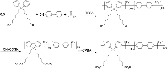
The procedures of preparation of Poly(FLx-BPy)-Br are illustrated in Scheme 1. The synthesis of Poly(FL50-BP50)-Br was as follows: 9,9-bis(6-bromohexyl)-fluorene (2.4617 g, 5 mmol) and biphenyl (0.7710 g, 5 mmol) were dissolved with 8 mL anhydrous dichloromethane. Then 1,1,1-trifluoroacetone (1.46 g, 13 mmol) was added before TFSA (8.4 mL) was added dropwise over 5 min at 0 °C. After TFSA was added completely, the solution was warmed to room temperature and stirred for 60 min. Finally, the mixture was poured into methanol and a white precipitate was obtained. The polymer was filtered, washed subsequently with deionized water and dried to afford Poly(FL40-BP60)-Br (3.92 g, 94% yield).Synthesis of Poly(FLx-BPy)-SAc
Taking the synthesis of Poly(FL50-BP50)-SAc as an example, Poly(FL50-BP50)-Br (3.52 g) and 40 mL DMAc were added into a flask. After the polymer was dissolved in DMAc, KSAc (1.926 g, 16.86 mmol) was placed into the flask. Then the mixture solution was stirred for 24 h at 50 °C. Finally, the reaction mixture was poured into methanol to obtain the product. The white product was washed with methanol and dried in a vacuum for 24 h (3.21 g, 92% yield).Synthesis of Poly(FLx-BPy)-SO3Na
Taking the synthesis of Poly(FL50-BP50)-SO3Na as an example, Poly(FL50-BP50)-SAc (3.8 g) was dissolved in 40 mL DMAc, and then 3-chloroperoxybenzoic acid (6.091 g, 30 mmol) was added at 0 °C. The reaction solution was warmed to room temperature and stirred for about 2 h, and eventually a gel-like solid was formed, locking the magneton without stirring. Then, the gel solid was taken out and placed in 1 M NaCl aqueous solution for precipitation. The resulting polymer was dissolved in DMSO and poured into ethyl acetate to complete purification twice. The purified polymer Poly(FL50-BP50)-SO3Na was dried in a vacuum (3.43 g, 89% yield).Preparation of Poly(FLx-BPy)-SO3H membranes
Poly(FL50-BP50)-SO3Na (1 g) and DMSO (20 mL) were mixed in a flask to form a 5 wt% polymer solution with continuous stirring at 60 °C. The solution was filtered and then cast onto a clean glass plate to evaporate solvent at 60 °C for 12 h. Then the polymer membrane was stripped from the glass plate and soaked in 1 M H2SO4 for 48 h to complete protonation to obtain Poly(FL50-BP50)-SO3H.Fabrication of MEAs and single cell performance
Poly(FL50-BP50)-SO3H was dissolved in ethanol (5 wt%) at room temperature to prepare as the universal ionomer (the digital photograph is shown in Fig. S1†) for Poly(FLx-BPy)-SO3H based MEAs. Then 0.100 g Pt/C (60 wt%, Johnson Matthey), 0.333 g water, and 2.500 g isopropyl were mixed with 0.222 g Poly(FL50-BP50)-SO3H ionomer solution (5 wt%) by ultrasonication to acquire a homogeneous catalyst ink. The procedure for Nafion 212 based MEA is similar to that for Poly(FLx-BPy)-SO3H except that the weight ratio of the Nafion ionomer and Pt/C was 1![[thin space (1/6-em)]](https://www.rsc.org/images/entities/char_2009.gif) :
:![[thin space (1/6-em)]](https://www.rsc.org/images/entities/char_2009.gif) 4. The catalyst coated membranes (CCMs, the digital photograph is shown in Fig. S2†) were obtained using an air spray gun to deposit the ink on both sides of PEMs with an active electrode area of 2.5 × 2.5 cm2 and the Pt loadings for the anode and cathode were both 0.2 mg cm−2. Finally, the CCMs were sandwiched between the cathode and anode gas diffusion electrodes (GDEs, Sigracet 22 BB, SGL Carbon) to manufacture the MEAs. The fuel cell performance was evaluated using an Arbin fuel cell testing system (Arbin Instrument Inc., USA) with H2 (400 sccm) and air (1000 sccm) or O2 (400 sccm) at 100% RH and under 2 bar backpressure at 80 °C.
4. The catalyst coated membranes (CCMs, the digital photograph is shown in Fig. S2†) were obtained using an air spray gun to deposit the ink on both sides of PEMs with an active electrode area of 2.5 × 2.5 cm2 and the Pt loadings for the anode and cathode were both 0.2 mg cm−2. Finally, the CCMs were sandwiched between the cathode and anode gas diffusion electrodes (GDEs, Sigracet 22 BB, SGL Carbon) to manufacture the MEAs. The fuel cell performance was evaluated using an Arbin fuel cell testing system (Arbin Instrument Inc., USA) with H2 (400 sccm) and air (1000 sccm) or O2 (400 sccm) at 100% RH and under 2 bar backpressure at 80 °C.
Characterization
1H NMR spectra and 19F NMR spectra of the polymers were obtained on a Bruker AV500 spectrometer. Tensile strength and the break elongation rate of PEMs were obtained on a universal testing machine (Instron-5966, USA) under environmental conditions with a speed of 1 mm min−1. A Mettler-Toledo TGA/DSC 3+/1100 LF analyzer was used to conduct thermogravimetric analysis (TGA) of polymers before and after sulfonation under a N2 flow from 50 to 800 °C (10 °C min−1). The transmission electron microscopy (TEM) images and small angle X-ray scattering (SAXS) profiles of PEMs were obtained on a JEM-1400 plus and SAXSess mc2 after the membranes were dyed with Pb(OAc)2·3H2O. A scanning electron microscope (SEM, Phenom Prox) was applied to observe surface morphology of the four PEMs and cross-sectional morphology of the MEA fabricated with the Poly(FL50-BP50)-SO3H membrane before and after the durability test. The molecular weight of Poly(FL50-BP50)-SO3H before and after the durability test was acquired by gel permeation chromatography (GPC, Waters GPC 1515) using DMF as an eluent with a flow rate of 1 mL min−1. The proton conductivity (σ) was obtained using a Solartron Analytical 1260 and 1287 using the following equation: σ (S cm−1) = L/RWd, where R represents the resistance of the membrane surveyed by four-point probe AC impedance spectroscopy over the frequency range of 106 to 1 Hz with a disturbance potential of 10 mV, L is the length of the two electrodes, and W and d are the width and thickness of the membrane, respectively. Electrochemical impedance spectroscopy (EIS) was conducted at 200 mA cm−2 with 5 mA cm−2 amplitude of the AC signal over the frequency range of 106 to 1 Hz. Linear sweep voltammetry (LSV) experiments were conducted to evaluate the H2 crossover with a humidified H2 flow rate of 400 sccm at the anode and humidified N2 flow rate of 400 sccm at the cathode. The cathode (working electrode) potential was scanned from 0.05 to 0.5 V with a rate of 5 mV s−1 at 80 °C. The anode served as the reference and counter electrodes. The H2 crossover current of the MEAs was calculated from the current at 0.4 V in the LSV curves. And the specific test methods for the proton conductivity, the water uptake (WU), swelling ratio (SR), oxidative stability and ion exchange capacity (IEC) are shown in our previous report.4Results and discussion
Synthesis of Poly(FLx-BPy)-SO3H
As shown in Scheme 1, the –Br groups on the side chains of Poly(FL50-BP50)-Br are replaced by –SAc via a nucleophilic substitution reaction, and then the –SAc of Poly(FL50-BP50)-SAc can be easily oxidized to sulfonate groups with 3-chloroperoxybenzoic acid. As shown in Fig. 1, after the –Br is replaced by –SAc, the peak of Hl shifts to the higher field and appears at δ = 2.71 ppm (Hl in poly(FL50-BP50)-SAc), while a new peak of Hm appears at 2.25 ppm, thus marking the completion of the substitution. And after further sulfonation, the peak of Hm disappears and the chemical shift value of Hl migrates to 2.454 ppm (Hl in Poly(FL50-BP50)-SO3H), demonstrating the completion of the sulfonation process. Besides, the 19F NMR spectra of Poly(FLx-BPy)-SO3H (Fig. 2a) have only one peak and the corresponding chemical shift values remain constant, indicating the high purity of the polymers. The 1H NMR spectra of other polymers can be seen in Fig. S3–S5.†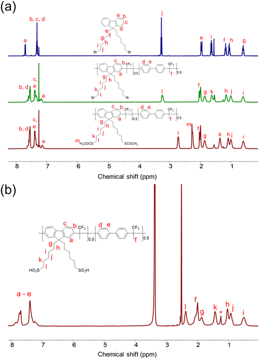 | ||
| Fig. 1 (a) 1H NMR spectra of 9,9-bis(6-bromohexyl)-fluorene and Poly(FL50-BP50)-Br and Poly(FL50-BP50)-SAc in CDCl3, and (b) 1H NMR spectra of Poly(FL50-BP50)-SO3H in DMSO-d6 (* = vacuum grease). | ||
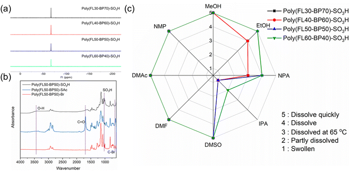 | ||
| Fig. 2 (a) 19F NMR spectra of Poly(FLx-BPy)-SO3H in DMSO-d6. (b) FT-IR spectra of Poly(FL50-BP50)-Br, Poly(FL50-BP50)-SAc and Poly(FL50-BP50)-SO3H. (c) Solubility properties of Poly(FLx-BPy)-SO3H. | ||
Furthermore, the FT-IR spectra (Fig. 2b and S6–S8†) also confirm the successful sulfonation process of polymers; the C–Br characteristic absorption peak at 643 cm−1 of Poly(FL50-BP50)-Br disappears, while the sharp absorption peak at 1690 cm−1 which originated from C![[double bond, length as m-dash]](https://www.rsc.org/images/entities/char_e001.gif) O of –SAc appears in Poly(FL50-BP50)-SAc spectra. Finally, the wide stretching vibration absorption peak at 3400 cm−1 of the O–H moiety and new peaks at 1072 and 1026 cm−1 of sulfonic acid groups of Poly(FL50-BPy-50)-SO3H increase in intensity. Fig. 2c presents the solubility difference of Poly(FLx-BPy)-SO3H. Poly(FLx-BPy)-SO3H membranes can be dissolved in most solvents mentioned in the radar chart and exhibit higher solubility as the SD. Surprisingly, Poly(FLx-BPy)-SO3H polymers exhibit favorable solubility in alcohol, which provides a good opportunity to prepare ionomers in catalyst layers, contributing to improving the performance of PEMFCs.
O of –SAc appears in Poly(FL50-BP50)-SAc spectra. Finally, the wide stretching vibration absorption peak at 3400 cm−1 of the O–H moiety and new peaks at 1072 and 1026 cm−1 of sulfonic acid groups of Poly(FL50-BPy-50)-SO3H increase in intensity. Fig. 2c presents the solubility difference of Poly(FLx-BPy)-SO3H. Poly(FLx-BPy)-SO3H membranes can be dissolved in most solvents mentioned in the radar chart and exhibit higher solubility as the SD. Surprisingly, Poly(FLx-BPy)-SO3H polymers exhibit favorable solubility in alcohol, which provides a good opportunity to prepare ionomers in catalyst layers, contributing to improving the performance of PEMFCs.
Thermogravimetric analysis
In general, sufficient thermal stability is necessary for PEMs in practical applications. Fig. 3a and b exhibit the TGA profiles of the pre- versus post- sulfonated polymers from 50 to 800 °C under a N2 flow. The degradation paths of the four pre-sulfonated Poly(FLx-BPy)-Br polymers are consistent. The four pre-sulfonated polymers show the standard two-stage degradation pathway. The first stage from 340 to 503 °C is the thermal decomposition of the bromoalkyl side-chains, and the mass losses at this stage gradually increase with the bromoalkyl content. Besides, the second weight losses at >530 °C primarily originated from thermal degradation of the polymer main-chains.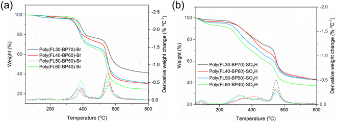 | ||
| Fig. 3 TGA curves in a N2 flow from 50 to 800 °C of (a) Poly(FLx-BPy)-Br and (b) Poly(FLx-BPy)-SO3H. | ||
The weight varying curves of the four PEMs mainly fall into three stages. In the range of 50 to 240 °C, all four PEMs have a small but varying degree of mass loss, which should be attributed to residual water within the Poly(FLx-BPy)-SO3H membranes. Moreover, an interesting phenomenon is that the mass losses of Poly(FLx-BPy)-SO3H membranes at this stage increase with the SD. The mass losses in the second section from 240 to 530 °C are mainly due to the decomposition of the sulfonation groups and the alkyl side-chains, which is similar to the characteristics exhibited in the first stage; the mass losses of this period improve with the SD. The section above 530 °C belongs to the third period, where mass losses are primarily caused by the degradation of the polymer backbone.
Proton conductivity, water uptake and swelling ratio
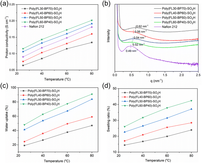
High proton conductivity is a vital index for PEMs. The proton conductivity of the four PEMs prepared in this work can be seen in Fig. 4a. Benefiting from the comb-like structure and high IEC (Table 1), Poly(FLx-BPy)-SO3H membranes all possess a high σ that provides outstanding power density. Poly(FL50-BP50)-SO3H (0.106 S cm−1 at 25 °C and 0.191 S cm−1 at 80 °C) and Poly(FL60-BP40)-SO3H (0.115 S cm−1 at 25 °C and 0.202 S cm−1 at 80 °C) membranes exhibit obviously higher σ compared to Poly(FL30-BP70)-SO3H (0.064 S cm−1 at 25 °C and 0.134 S cm−1 at 80 °C) and Poly(FL40-BP60)-SO3H (0.076 S cm−1 at 25 °C and 0.160 S cm−1 at 80 °C) due to the formation of continuous hydrophilic ion channels. Besides, the proton conduction activation energy (Ea) calculated with Arrhenius plots of Poly(FLx-BPy)-SO3H (Fig. S9†) is found to be in the range of 8.8–11.9 kJ mol−1 with a tendency of lower Ea for higher SD, indicating the enhanced proton conduction capacity with the increased SD. The WU (Fig. 4c) and SR (Fig. 4d) of the prepared Poly(FLx-BPy)-SO3H membranes were measured from 25 to 80 °C; Poly(FLx-BPy)-SO3H membranes have a high WU (47–91% at 80 °C) in liquid water, while Poly(FLx-BPy)-SO3H displays a moderate SR (24–42% at 80 °C) with a trend of higher WU and SR for higher SD. These data reveal that the combination of rigid ether-free hydrophobic main-chains and a locally double sulfohexyl side-chains comb-like structure improves σ and dimensional stability of Poly(FLx-BPy)-SO3H.| PEMs | Tensile strength (MPa) | Young's modulus (MPa) | Elongation at break (%) | Residual weighta (%) | Theoretical IECb (meq g−1) | Titrated IECc (meq g−1) |
|---|---|---|---|---|---|---|
| a Residual weight of Poly(FLx-BPy)-SO3H under Fenton's reagent at 80 °C for 4 h. b Theoretical IEC was calculated from the integration of 1H NMR spectra. c Titrated IEC was calculated by titration with 0.01 M NaOH using phenolphthalein as the indicator. Before titration, the membranes were immersed into 1 M NaCl solution for 24 h to promote the ion exchange. | ||||||
| Poly(FL30-BP70)-SO3H | 37.9 | 894 | 6.5 | 99.6 | 1.71 | 1.64 |
| Poly(FL40-BP60)-SO3H | 39.5 | 1169 | 4.8 | 99.5 | 2.08 | 1.93 |
| Poly(FL50-BP50)-SO3H | 49.1 | 1177 | 4.5 | 99.5 | 2.39 | 2.21 |
| Poly(FL60-BP40)-SO3H | 51.6 | 1189 | 4.1 | 99.4 | 2.65 | 2.54 |
Mechanical properties and oxidative stability
To meet the actual application, the PEMs must have enough mechanical strength and oxidation resistance.42 Related mechanical properties and the oxidative stability data are summarized in Table 1, and the stress–strain curves of Poly(FLx-BPy)-SO3H membranes can be seen in Fig. S10.† As presented in Table 1, the tensile strength and Young's modulus of Poly(FLx-BPy)-SO3H are in the sequence of Poly(FL60-BP40)-SO3H (51.6 MPa and 1189 MPa) > Poly(FL50-BP50)-SO3H (49.1 MPa and 1177 MPa) > Poly(FL40-BP60)-SO3H (39.5 MPa and 1169 MPa) > Poly(FL30-BP70)-SO3H (37.9 MPa and 894 MPa). Meanwhile, the break elongation follows the order of Poly(FL60-BP40)-SO3H (4.1%) < Poly(FL50-BP50)-SO3H (4.5%) < Poly(FL40-BP60)-SO3H (4.8%) < Poly(FL30-BP70)-SO3H (6.5%) as a result of reduced fluorene content and polymer rigidity.Preeminent oxidative stability is essential for the practical application of PEMs. The PEMs were immersed in Fenton's reagent at 80 °C for 4 h to test their oxidative stability. As a benefit of the ether-free polyaromatic backbone, the Poly(FLx-BPy)-SO3H membranes remained intact and the residual weight ranged above 99% (Table 1) after the test, which provided fundamental support for the durability of the corresponding MEA.
Morphology
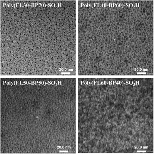
In general, it is of great significance to form distinct microphase separation morphology within PEMs, because it will remarkably enhance the proton conduction capacity and help to contain swelling.43 Herein, the TEM characterization of Poly(FLx-BPy)-SO3H was performed and is shown in Fig. 5; the bright region represented the hydrophobic section and the dark region represented the hydrophilic portion formed by the ionic clusters. When the SD increases from 30% to 40%, the density of hydrophilic ion clusters gradually improves, and when the SD increases from 40% to 50%, the hydrophilic ion clusters begin to aggregate to form continuous hydrophilic ion channels, which will help to further enhance its proton conductivity as well as water uptake. Ultimately, as the SD improves from 50% to 60%, the degree of continuity and size of hydrophilic ion channels increase ulteriorly due to the agglomeration of more sulfonic acid groups. Besides, the microphase separation morphology in Poly(FLx-BPy)-SO3H was further verified by SAXS. The sizes of the ion clusters or channels calculated using SAXS profiles (Fig. 4b) are approximately 10.1, 11.2, 11.6, 12.1 and 12.8 nm for Poly(FL30-BP70)-SO3H, Poly(FL40-BP60)-SO3H, Poly(FL50-BP50)-SO3H, Poly(FL60-BP40)-SO3H and Nafion 212, respectively. Both TEM and SAXS data certify that well-developed microphase separation is formed in Poly(FLx-BPy)-SO3H with the hydrophilic flexible side chains. Thereinto, Poly(FL50-BP50)-SO3H and Poly(FL60-BP40)-SO3H possess continuous hydrophilic ion channels.Fuel cell performance
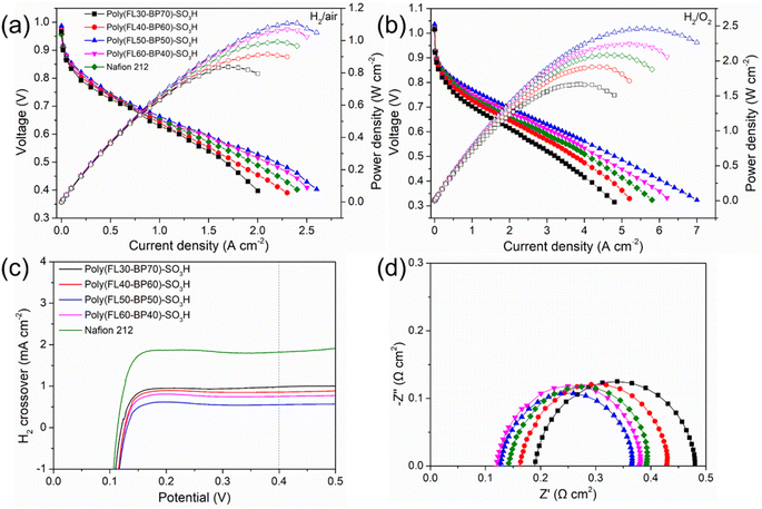
To estimate the feasibility of the prepared membranes in PEMFCs, the performance of MEAs integrated with Poly(FLx-BPy)-SO3H and Nafion 212 was tested under H2/air or H2/O2 conditions. Considering the good solubility in alcohols or the mixture of alcohols with water, high proton conductivity, and dimensional stability in hot water, we selected Poly(FL50-BP50)-SO3H as the universal ionomer for Poly(FLx-BPy)-SO3H based MEAs. Fig. 6a and b show the polarization and power density curves of the MEAs with 100% RH H2 and air or O2 under 2 bar backpressure at 80 °C. The open-circuit voltages (OCVs) of Poly(FLx-BPy)-SO3H are 0.967–0.987 V for H2/air and 1.016–1.036 V for H2/O2, slightly lower than that of the Nafion 212 based MEA (0.957 V for H2/air and 1.013 V for H2/O2) (Table S1†), suggesting the low H2 permeability of Poly(FLx-BPy)-SO3H membranes. The PPD of MEAs is in the order of Poly(FL50-BP50)-SO3H (MEA3, 1.108 W cm−2 for H2/air and 2.465 W cm−2 for H2/O2) > Poly(FL60-BP40)-SO3H (MEA4, 1.070 W cm−2 for H2/air and 2.242 W cm−2 for H2/O2) > Nafion 212 (MEA5, 0.992 W cm−2 for H2/air and 2.080 W cm−2 for H2/O2) > Poly(FL40-BP60)-SO3H (MEA2, 0.916 W cm−2 for H2/air and 1.915 W cm−2 for H2/O2) > Poly(FL30-BP70)-SO3H (MEA1, 0.837 W cm−2 for H2/air and 1.668 W cm−2 for H2/O2). Although Poly(FL60-BP40)-SO3H has a higher proton conductivity than Poly(FL50-BP50)-SO3H, MEA4 does not display expected fuel cell performance but MEA3 delivers one of the best performances in PEMFCs as compared with recent publications (Table S2†). Poly(FL60-BP40)-SO3H has a higher IEC than Poly(FL50-BP50)-SO3H, which is accompanied by a significant increase in water uptake and dimensional swelling, loss in mechanical strength, or even deterioration of the MEA at elevated temperatures. Besides, the subtle incompatibility of the Poly(FL60-BP40)-SO3H membrane and Poly(FL50-BP50)-SO3H ionomer also leads to the performance deterioration of MEA4. This result confirms that relatively high content of sulfohexyl groups and high miscibility of membranes with ionomers are beneficial for the fuel cell performance.Furthermore, the H2 permeability of MEA1-5 was calculated by using the linear sweep voltammograms (LSVs) with H2 and N2 for the anode and cathode at 80 °C and 100% RH. As shown in Fig. 6c, the H2 crossover current densities of MEA1-4 are 0.986, 0.862, 0.755 and 0.554 mA cm−2, respectively, which are lower than that of MEA5 (1.827 mA cm−2) and in line with the trend of OCVs. It is noticeable that the sulfoalkyl-tethered polymers possess a smooth and imperforate surface (Fig. S11†) as well as a dense structure and the higher the content of the densely sulfonated structure the greater the barrier function for hydrogen permeation.
The Nyquist plot obtained at 0.2 A cm−2 (∼0.8 V, kinetic region) consists of one semicircle that reflects the charge transfer resistance (RCT). In the kinetic region, the main contribution of RCT arises from the cathodic oxygen reduction reaction (ORR). The real axis intercept indicates the ohmic resistance of the MEA (RΩ), which is the sum of (a) ionic resistance within the electrolytes, (b) electronic resistance within the cell's hardware, and (c) contact resistance within the inter connections.44 It can be observed in Fig. 6d that as the SD increases, the RΩ of Poly(FLx-BPy)-SO3H based MEAs decreases from 0.189 to 0.120 Ω cm2, whereas the value for the MEA fabricated with Nafion 212 and the Nafion ionomer (MEA5) is 0.141 Ω cm2. In general, a huge proportion of RΩ is mainly caused by the ion migration resistance of the membrane under operating conditions. Accordingly, this result is in agreement with the proton conductivity of the PEMs.
Different from trend of RΩ, the RCT of Poly(FLx-BPy)-SO3H based MEAs is in the range of 0.237 to 0.291 Ω cm2, and the Poly(FL50-BP50)-SO3H based MEA (MEA3) possesses the lowest RCT. The subtle difference originates from the favorable compatibility between the Poly(FL50-BP50)-SO3H membrane and the Poly(FL50-BP50)-SO3H ionomer. As a result, MEA4, consisting of the Poly(FL60-BP40)-SO3H membrane and Poly(FL50-BP50)-SO3H ionomer, exhibits a higher RCT (0.260 Ω cm2) than MEA3 (0.237 Ω cm2). The RCT of MEA5 is 0.251 Ω cm2, higher than that of MEA3, but lower than that of the MEA fabricated with Poly(FL30-BP70)-SO3H (MEA1, 0.291 Ω cm2) and Poly(FL40-BP60)-SO3H (MEA2, 0.266 Ω cm2), suggesting the high electrochemical activity of homogeneous MEA featuring high proton conductivity and identical chemical structure of the membrane and ionomer.
To further evaluate the compatibility of the PEMs and ionomers, the mass activities (MAs) of the Poly(FL50-BP50)-SO3H bonded electrode for Poly(FLx-BPy)-SO3H and Nafion bonded MEA of Nafion 212 were calculated from the current density at 0.9 V and cathodic Pt loading (Fig. S12†). MEA3 exhibits the highest MA with a value of 0.165 A mg−1 for H2/air and 0.281 A mg−1 for H2/O2, indicating the boosted Pt utilization efficiency for the ORR. Besides, the MA of MEA4 (0.156 A mg−1 for H2/air and 0.254 A mg−1 for H2/O2) is also higher than that of the Nafion one (0.122 A mg−1 for H2/air and 0.230 A mg−1 for H2/O2) while the values for MEA1 (0.084 A mg−1 for H2/air and 0.171 A mg−1 for H2/O2) and MEA2 (0.096 A mg−1 for H2/air and 0.207 A mg−1 for H2/O2) are lower than that of MEA5, consistent with the trend of the above proton conductivity results. Consequently, the high proton conductivity of the PEMs is favorable to enhance intrinsic activity towards the ORR and the Poly(FL50-BP50)-SO3H membrane is more compatible with identical ionomers in the catalyst layers.
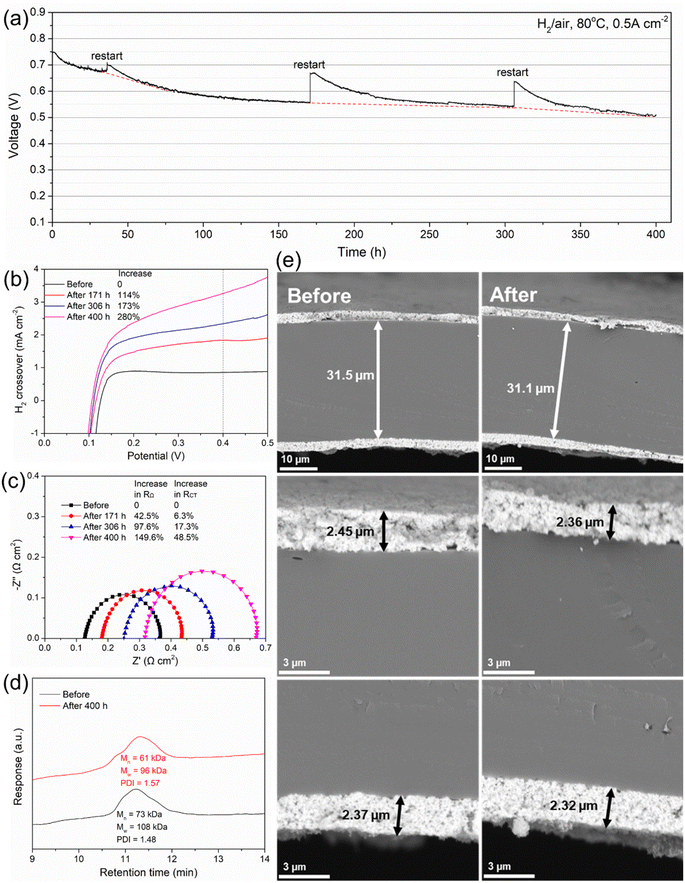
Durability is an extremely important indicator to evaluate the practical application potential of PEMs. Taking the high performance of Poly(FL50-BP50)-SO3H into account, MEA3 was used for the durability test at a constant current density of 0.5 A cm−2 (Fig. 7a). In the first 36 h, the voltage drops rapidly from the initial 0.750 V to 0.684 V with a voltage decay rate of 1.83 mV h−1. Then the voltage drops slightly from 0.684 V to 0.510 V with a decay rate of 0.48 mV h−1. The durability of MEA3 is one of the highest compared to other recent reports (Table S2†).
The decay in voltage of MEAs might be caused by cathode flooding, platinum oxidation, degradation of the membrane and ionomer, contaminant adsorption, etc.45 The detailed reasons need to be further explored. During the durability measurement of MEA3, several restarts were experienced to regain recoverable performance. As shown in Fig. 7b, the H2 crossover current density increases with time, where the value after 171, 306 and 400 h increases by 114%, 173% and 280%, respectively.
The EIS test was further conducted to get insight into the degradation of MEA3. It can be seen in Fig. 7c that both the real axis intercept and diameter of each impedance semicircle increase with time. From 171 to 400 h, the RΩ of the Poly(FL50-BP50)-SO3H based MEA increases by 42.5–149.6% while the RCT increases by 6.3–48.5%.Besides, the relative change in H2 crossover (280%) before and after the durability test demonstrates much larger variation than the relative change in RCT (48.5%), indicating that the voltage loss mainly arises from the degradation of the proton pathway within the membrane.
After the durability test, MEA3 was disassembled, and Poly(FL50-BP50)-SO3H was carefully recovered by dissolving the MEA fragments into DMSO for post-test analyses. Then the chemical degradation of the membrane was studied by GPC and NMR techniques. As shown in Fig. 7d, GPC analyses suggest a loss in the molecular weight from a number-average molecular weight (Mn) of 73 kDa and weight-average molecular weight (Mw) of 108 kDa for the pristine PEM to Mn = 61 kDa and Mw = 96 kDa for the recovered PEM. The Mw decreases by 11% while the polydispersity index (PDI) increases slightly from 1.48 to 1.57, indicating that the loss is dominated by the degradation of sulfonic acid groups, rather than the ether-free polymer backbone because the degradation of the polymer backbone will lead to an evident increase in the PDI. Besides, the 1H and 19F NMR spectra (Fig. S13†) of the post-test membrane also display minor differences in the chemical structure, further confirming the durability of the ether-free main chain in the Poly(FL50-BP50)-SO3H membrane under operating conditions.
The cross-section morphology of MEA3 before and after the durability test was investigated to evaluate the strength of catalyst layers/membrane layers. As shown in Fig. 7e, the thickness of the catalyst layers (anode or cathode) and membrane layer of the original MEA is ∼2.4 and ∼31.5 μm, respectively. After 400 h of operation, the thickness of the three layers decreases slightly and there is no delamination or rupture at the interfaces. The great durability of interfaces can be attributed to two reasons: (1) the high chemical stability of the ether-free polymer backbone and (2) high interfacial compatibility with the membrane and identical ionomer in the catalyst layers. These results also support that the voltage loss mainly arises from the PEMs rather than the catalyst layers and the slight drop in Mw would cause great changes in the proton conduction within the MEA.
Conclusions
In this work, a series of high-performance ether-free Poly(FLx-BPy)-SO3H polymers with a locally double sulfonated side-chain comb-like structure have been proposed. The ether-free aromatic backbones provide the fundamental support for achieving excellent MEA stability. The comb-like structure results in well-developed microphase separation morphology. Therefore, continuous ion channels are built finally within the membranes as a result of the obvious difference between the hydrophobic main-chains and the flexible hydrophilic side-chains. The PEMFCs using a Poly(FL50-BP50)-SO3H membrane and ionomer with identical chemical structures deliver comparable power outputs (1.108 W cm−2 for H2/air and 2.465 W cm−2 for H2/O2) to state-of-the-art aromatic polymer based PEMFCs, and excellent MEA stability greater than 400 h at 0.5 A cm−2. All these results demonstrate that Poly(FLx-BPy)-SO3H PEMs are sufficiently promising candidates for PEMFCs.Conflicts of interest
The authors declare no conflict of interest.Acknowledgements
This work was supported by the National Key Research and Development Program of China (2018YFB1502301) and the National Natural Science Foundation of China (22279157 and 22179140).References
- D. W. Shin, M. D. Guiver and Y. M. Lee, Chem. Rev., 2017, 117, 4759–4805 CrossRef CAS PubMed.
- W. Li, J. Jiang, H. An, S. Dong, Z. Yue, H. Qian and H. Yang, ACS Appl. Energy Mater., 2021, 4, 2732–2740 CrossRef CAS.
- Q. He, T. Xu, H. Qian, J. Zheng, C. Shi, Y. Li and S. Zhang, J. Power Sources, 2015, 278, 590–598 CrossRef CAS.
- L. Lei, X. Zhu, J. Xu, H. Qian, Z. Zou and H. Yang, J. Power Sources, 2017, 350, 41–48 CrossRef CAS.
- S. Gao, H. Xu, T. Luo, Y. Guo, Z. Li, A. Ouadah, Y. Zhang, Z. Zhang and C. Zhu, J. Membr. Sci., 2017, 536, 1–10 CrossRef CAS.
- J. Han, K. Kim, S. Kim, H. Lee, J. Kim, T. Ko, J. Bae, W. J. Choi, Y.-E. Sung and J.-C. Lee, J. Power Sources, 2020, 448, 227427 CrossRef CAS.
- J. E. Park, J. Kim, J. Han, K. Kim, S. Park, S. Kim, H. S. Park, Y.-H. Cho, J.-C. Lee and Y.-E. Sung, J. Membr. Sci., 2021, 620, 118871 CrossRef CAS.
- D. Yuan, Y. Qin, S. Li, S. Du, Y. Xu, Q. Weng, P. Chen, X. Chen and Z. An, J. Power Sources, 2021, 484, 229265 CrossRef CAS.
- J. Ahn, R. Shimizu and K. Miyatake, J. Mater. Chem. A, 2018, 6, 24625–24632 RSC.
- P. Y. You, S. K. Kamarudin and M. S. Masdar, Int. J. Hydrogen Energy, 2019, 44, 1857–1866 CrossRef CAS.
- F. Mack, K. Aniol, C. Ellwein, J. Kerres and R. Zeis, J. Mater. Chem. A, 2015, 3, 10864–10874 RSC.
- J. Chen, L. Wang and L. Wang, ACS Appl. Mater. Interfaces, 2020, 12, 41350–41358 CrossRef CAS PubMed.
- Y. Zhang, Y. Pu, P. Yang, H. Yang, S. Xuan, J. Long, Y. Wang and H. Zhang, J. Mater. Sci., 2018, 53, 14506–14524 CrossRef CAS.
- D. Yuan, Y. Qin, S. Li, S. Du, Y. Xu, Q. Weng, P. Chen, X. Chen and Z. An, J. Membr. Sci., 2021, 621, 118932 CrossRef CAS.
- A. P. Soleymani, L. R. Parent and J. Jankovic, Adv. Funct. Mater., 2022, 32, 2105188 CrossRef CAS.
- X. Liu, J. Zhang, C. Zheng, J. Xue, T. Huang, Y. Yin, Y. Qin, K. Jiao, Q. Du and M. D. Guiver, Energy Environ. Sci., 2020, 13, 297–309 RSC.
- H. Hu, Y. Sui, M. Ueda, J. Qian, L. Wang and X. Zhang, J. Membr. Sci., 2018, 564, 342–351 CrossRef CAS.
- K. Kang and D. Kim, J. Membr. Sci., 2019, 578, 103–110 CrossRef CAS.
- B. B. Munavalli and M. Y. Kariduraganavar, J. Membr. Sci., 2018, 566, 383–395 CrossRef CAS.
- Z. Yao, Z. Zhang, M. Hu, J. Hou, L. Wu and T. Xu, J. Membr. Sci., 2018, 547, 43–50 CrossRef CAS.
- J. Zheng, W. Bi, X. Dong, J. Zhu, H. Mao, S. Li and S. Zhang, J. Membr. Sci., 2016, 517, 47–56 CrossRef CAS.
- S. Chandra Sutradhar, M. M. Rahman, F. Ahmed, T. Ryu, l. Jin, S. Yoon, S. Lee, Y. Jin and W. Kim, J. Power Sources, 2019, 442, 227233 CrossRef CAS.
- M. K. Pagels, S. Adhikari, R. C. Walgama, A. Singh, J. Han, D. Shin and C. Bae, ACS Macro Lett., 2020, 9, 1489–1493 CrossRef CAS PubMed.
- H. A. Patel, J. Selberg, D. Salah, H. Chen, Y. Liao, S. K. Mohan Nalluri, O. K. Farha, R. Q. Snurr, M. Rolandi and J. F. Stoddart, ACS Appl. Mater. Interfaces, 2018, 10, 25303–25310 CrossRef CAS PubMed.
- M. R. Hibbs, C. H. Fujimoto and C. J. Cornelius, Macromolecules, 2009, 42, 8316–8321 CrossRef CAS.
- M. S. Cha, J. E. Park, S. Kim, S.-H. Han, S.-H. Shin, S. H. Yang, T.-H. Kim, D. M. Yu, S. So, Y. T. Hong, S. J. Yoon, S.-G. Oh, S. Y. Kang, O.-H. Kim, H. S. Park, B. Bae, Y.-E. Sung, Y.-H. Cho and J. Y. Lee, Energy Environ. Sci., 2020, 13, 3633–3645 RSC.
- N. R. Kang, T. H. Pham and P. Jannasch, ACS Macro Lett., 2019, 8, 1247–1251 CrossRef CAS PubMed.
- J. S. Olsson, T. H. Pham and P. Jannasch, Adv. Funct. Mater., 2018, 28, 1702758 CrossRef.
- P. Zuo, Y. Li, A. Wang, R. Tan, Y. Liu, X. Liang, F. Sheng, G. Tang, L. Ge, L. Wu, Q. Song, N. B. McKeown, Z. Yang and T. Xu, Angew. Chem., Int. Ed., 2020, 59, 2–12 CrossRef.
- N. Chen, C. Hu, H. H. Wang, S. P. Kim, H. M. Kim, W. H. Lee, J. Y. Bae, J. H. Park and Y. M. Lee, Angew. Chem., Int. Ed., 2021, 60, 7710–7718 CrossRef CAS PubMed.
- J. Wang, Y. Zhao, B. P. Setzler, S. Rojas-Carbonell, C. Ben Yehuda, A. Amel, M. Page, L. Wang, K. Hu, L. Shi, S. Gottesfeld, B. Xu and Y. Yan, Nat. Energy, 2019, 4, 392–398 CrossRef CAS.
- Z. Li, J. Guo, J. Zheng, T. A. Sherazi, S. Li and S. Zhang, Macromolecules, 2020, 53, 10998–11008 CrossRef CAS.
- N. Chen, H. H. Wang, S. P. Kim, H. M. Kim, W. H. Lee, C. Hu, J. Y. Bae, E. S. Sim, Y. C. Chung, J. H. Jang, S. J. Yoo, Y. Zhuang and Y. M. Lee, Nat. Commun., 2021, 12, 2367 CrossRef CAS PubMed.
- J. Zhang, K. Zhang, X. Liang, W. Yu, X. Ge, M. A. Shehzad, Z. Ge, Z. Yang, L. Wu and T. Xu, J. Mater. Chem. A, 2020, 9, 327–337 RSC.
- X. Luo, D. I. Kushner, J. Li, E. J. Park, Y. S. Kim and A. Kusoglu, Adv. Funct. Mater., 2021, 31, 2008778 CrossRef CAS.
- M. Hwang, K. Nixon, R. Sun, C. Willis and Y. A. Elabd, J. Membr. Sci., 2021, 633, 119330 CrossRef CAS.
- X. Pu, Y. Duan, J. Li, C. Ru and C. Zhao, J. Power Sources, 2021, 493, 229671 CrossRef CAS.
- N. Chen, S. Y. Paek, J. Y. Lee, J. H. Park, S. Y. Lee and Y. M. Lee, Energy Environ. Sci., 2021, 14, 6338–6348 RSC.
- K. Yang, X. Li, J. Guo, J. Zheng, S. Li, S. Zhang, X. Cao, T. A. Sherazi and X. Liu, J. Membr. Sci., 2020, 596, 117720 CrossRef CAS.
- K. Miyatake, H. Zhou, H. Uchida and M. Watanabe, Chem. Commun., 2003, 3, 368–369 RSC.
- B. Muthuraj, S. Mukherjee, C. Patra and P. Iyer, ACS Appl. Mater. Interfaces, 2016, 8, 32220–32229 CrossRef CAS PubMed.
- Z. Long, J. Miyake and K. Miyatake, J. Mater. Chem. A, 2020, 8, 12134–12140 RSC.
- X. Liu, Y. Li, J. Xue, W. Zhu, J. Zhang, Y. Yin, Y. Qin, K. Jiao, Q. Du, B. Cheng, X. Zhuang, J. Li and M. D. Guiver, Nat. Commun., 2019, 10, 842 CrossRef PubMed.
- U. Reimer, W. Lehnert, Y. Holade and B. Kokoh, in Fuel Cells and Hydrogen, ed. V. Hacker and S. Mitsushima, Elsevier 2018, ch. 2 Search PubMed.
- M. Zago, A. Baricci, A. Bisello, T. Jahnke, H. Yu, R. Maric, P. Zelenay and A. Casalegno, J. Power Sources, 2020, 455, 227990 CrossRef CAS.
Footnote |
| † Electronic supplementary information (ESI) available. See DOI: https://doi.org/10.1039/d2ta08911d |
| This journal is © The Royal Society of Chemistry 2023 |

