
Lithium–sulfur cells with a sulfide solid electrolyte/polysulfide cathode interface†
Yin-Ju
Yen
a and
Sheng-Heng
Chung
 *ab
*ab
aDepartment of Materials Science and Engineering, National Cheng Kung University, Tainan 70101, Taiwan. E-mail: SHChung@gs.ncku.edu.tw
bHierarchical Green-Energy Materials Research Center, National Cheng Kung University, Tainan 70101, Taiwan
First published on 4th January 2023
Abstract
Lithium–sulfur batteries use a solid electrolyte as an alternative to the conventional liquid electrolyte to form solid-state lithium–sulfur cells with a high energy density. Sulfur cathodes are the common active material used in conjunction with solid electrolytes. However, their insulating nature and the solid–solid interface with the solid electrolyte result in poor cyclability and low active material loading. In this study, we adopt a polysulfide cathode and a sulfide solid electrolyte to generate a novel lithium-sulfur cell configuration. The liquid–solid interface provided by the polysulfide catholyte allows a close connection between the electrode and electrolyte, enhancing charge transfer and lithium-ion diffusion. The improved interface means that the polysulfide cathode exhibits high reactivity, allowing us to achieve a high sulfur loading (5 mg cm−2), a high areal capacity (5.1 mA h cm−2), and a long cycle life (approaching 100 cycles). X-ray photoelectron spectroscopy and time-of-flight secondary ion mass spectroscopy confirm the formation of lithium phosphide and lithium phosphate on the cathode side of the electrolyte. These compounds form an ionically conductive protection layer that optimizes the contact between the polysulfide cathode and the solid electrolyte and stabilizes the active electrodes, thereby enhancing the kinetics and stability of the electrochemical reaction.
Introduction
Lithium–sulfur batteries are electrochemical conversion systems powered by the reversible redox reactions of a sulfur-based active electrode. Their high theoretical charge storage capacity (1675 mA h g−1), high abundance, and low material cost of sulfur make them promising candidates for next-generation energy storage devices.1,2 During the electrochemical conversion of sulfur, solid sulfur is reduced to liquid lithium polysulfides (Li2Sn, 4 ≤ n ≤ 8) and solid lithium sulfide (Li2S). The oxidation follows the reversible transformation path from the end-discharge product (Li2S) to the end-charge product (sulfur) through the conversion of polysulfide intermediates. Owing to the lithium–sulfur cells' high and reversible electrochemical utilization of sulfur, they have a high energy density (theoretically 2600 W h kg−1), which is several times that of a traditional lithium-ion battery cathode.3,4 The conversion battery chemistry of lithium-sulfur inspires the development of solid sulfur, solid sulfide, and liquid polysulfide as the starting active materials. Solid cathodes adopt the mature electrode technology from the lithium-ion battery, and have shown high cathode performance based on a facile preparation method. A liquid polysulfide cathode with strong reaction activity demonstrates a good electrochemical efficiency and stability of a high-loading cathode, which are keys for high-energy-density lithium-sulfur batteries.3–7The development of a lithium–sulfur battery is determined based on three independent but related cell fabrication parameters: the sulfur loading, the sulfur content, and the electrolyte-to-sulfur ratio. To realize high-energy-density lithium–sulfur cells, it is essential to develop a cathode with a high loading and content of the active material at low liquid electrolyte-to-sulfur ratios.3,5 However, decades of research have shown that it is difficult for cells with a high-sulfur-loading cathode to operate under lean liquid electrolyte conditions.3–7 The future development targets solid-state batteries, including lithium-ion cells and lithium-sulfur cells, that aim to have ionically conductive solid electrolyte materials (e.g., polymers, oxides, and sulfides)8–12 instead of the conventional liquid electrolyte and thus simultaneously achieve lean liquid electrolyte conditions and exhibit enhanced operational safety.8,9,13 Among various solid electrolyte materials, sulfides have relatively high ionic conductivities and low melting points that allow close contact between particles without a high-temperature annealing process being required. Furthermore, various sulfides with different ionic conductivities can be formed in the synthesis process by adjusting the reaction stoichiometry in the Li2S/phosphorus pentasulfide (P2S5) binary system.14 The common configuration of a solid-state lithium–sulfur cell features a sulfur cathode in contact with a sulfide solid electrolyte. However, the solid–solid interface between solid cathodes (i.e., sulfur and sulfide) and solid electrolyte as well as the insulating nature of solid cathodes lead to a high charge transfer resistance at the interface, which blocks the electrochemical reaction.15 Therefore, research has mainly focused on modifying the sulfur cathode (e.g., by using carbon or sulfide materials as additives) and interfacial engineering (i.e., by applying a coating to the interface) with the aim of achieving high-loading, high-content, and high-energy-density solid-state lithium–sulfur batteries with reversible cyclability.15–18
In this study, we demonstrated a concept for designing lithium–sulfur batteries in which the conventional liquid electrolyte is replaced with a sulfide solid electrolyte, and a traditional solid cathode is replaced with a polysulfide cathode. The solid electrolyte blocked polysulfide diffusion, while stabilizing smooth lithium-ion diffusion. The polysulfide cathode contributed to the high electrochemical reactivity and generated a liquid–solid interface with a fast charge-transfer path, which enhanced the electrochemical reaction kinetics and protected the interface stability with an ionic conductive passivation layer. Thus, the lithium/sulfide (Li3PS4)/polysulfide cell design enabled the high-sulfur-loading cathodes (3–5 mg cm−2 loading and 66 wt% content) to attain a high areal capacity (3.1–5.1 mA h cm−2) and high energy densities (6.8–11.3 mW h cm−2) with an extended cycle life (approaching 100 cycles).
In addition, we comprehensively examined the interfaces between the sulfide solid electrolyte and the polysulfide cathode and the lithium anode. Depth profiling confirmed the formation of lithium phosphide (Li3P) and lithium phosphate (Li3PO4), which mainly occurred on the cathode side of the solid electrolyte due to initial in situ chemical reactions with the polysulfide. Li3P and Li3PO4 are ionically conductive materials and acted as protective layers during the cycling test that also enhanced charge transfer at the interface, thereby enhancing electrochemical utilization and reversibility. These protective layers also prevented the polysulfides from freely penetrating the solid electrolyte, irreversibly diffusing from the cathode, and uncontrollably damaging the lithium anode. Thus, the electrochemical stability and efficiency were enhanced.
Experimental
Li3PS4 solid electrolyte and Li2S6 polysulfide cathode
The sulfide solid electrolyte powder was synthesized by mixing Li2S (Alfa Aesar) and phosphorus pentasulfide (Acros Organics) in a 75![[thin space (1/6-em)]](https://www.rsc.org/images/entities/char_2009.gif) :25 molar ratio using a planetary ball-milling method (PM100, Retsch). The mixture was sealed under an argon atmosphere in a 50 mL zirconia ball-milling jar with an air-tight clamp. Then, the ball-milling process was carried out at 380 rpm for 20 h using seven zirconia balls with a diameter of 10 mm and ten zirconia balls with a diameter of 3 mm. The Li2S–P2S5 solid electrolyte was fabricated from 100 mg of the ball-milled sulfide powder, which was pressed into a 13 mm die with a hydraulic press under a pressure of 4 tons at 25 °C for 30 s. The obtained solid electrolyte pellet was used to measure the ionic conductivity in a lithium/lithium symmetric cell with a configuration of lithium/Li3PS4/lithium. The electrochemical performance of the lithium/polysulfide cell with a configuration of lithium/Li3PS4/polysulfide was also assessed. The Li2S6 polysulfide catholyte with a concentration of 0.5 M was made by mixing sulfur (Alfa Aesar) and Li2S in a 5:1 molar ratio at 70 °C for 48 h in a blank electrolyte. The blank electrolyte was prepared from 1.85 M lithium bis(trifluoromethanesulfonyl)imide (LiTFSI, Sigma Aldrich) and 0.2 M lithium nitrate (Alfa Aesar) in a solvent mixture with 1,3-dioxolane and 1,2-dimethoxyethane (both Alfa Aesar) at a volumetric ratio of 40:55.19
:25 molar ratio using a planetary ball-milling method (PM100, Retsch). The mixture was sealed under an argon atmosphere in a 50 mL zirconia ball-milling jar with an air-tight clamp. Then, the ball-milling process was carried out at 380 rpm for 20 h using seven zirconia balls with a diameter of 10 mm and ten zirconia balls with a diameter of 3 mm. The Li2S–P2S5 solid electrolyte was fabricated from 100 mg of the ball-milled sulfide powder, which was pressed into a 13 mm die with a hydraulic press under a pressure of 4 tons at 25 °C for 30 s. The obtained solid electrolyte pellet was used to measure the ionic conductivity in a lithium/lithium symmetric cell with a configuration of lithium/Li3PS4/lithium. The electrochemical performance of the lithium/polysulfide cell with a configuration of lithium/Li3PS4/polysulfide was also assessed. The Li2S6 polysulfide catholyte with a concentration of 0.5 M was made by mixing sulfur (Alfa Aesar) and Li2S in a 5:1 molar ratio at 70 °C for 48 h in a blank electrolyte. The blank electrolyte was prepared from 1.85 M lithium bis(trifluoromethanesulfonyl)imide (LiTFSI, Sigma Aldrich) and 0.2 M lithium nitrate (Alfa Aesar) in a solvent mixture with 1,3-dioxolane and 1,2-dimethoxyethane (both Alfa Aesar) at a volumetric ratio of 40:55.19
Material characterization
The crystalline structure and the chemical composition of the sulfide electrolyte precursor were characterized by X-ray diffractometry (XRD, D8 Discover, Bruker) with Cu Kα radiation from 10° to 80° and a micro-Raman system (Jobin Yvon/Labram HR, ULVAC) from 200 to 2000 cm−1 with 532 nm excitation. The surface morphology and elemental distribution of the fresh and cycled sulfide solid electrolyte pellets and lithium anode were examined using a high-resolution field-emission scanning electron microscope (SEM, SU8000, Hitachi) equipped with an energy dispersive X-ray spectrometer (EDS, XFlash 5010, Bruker). X-ray photoelectron spectroscopy (XPS) of the fresh and cycled sulfide solid electrolyte pellets was performed using a surface analysis instrument (PHI 5000 VersaProbe, Ulvac-phi), and the data were fitted using CasaXPS software after subtracting the Shirley-type background. For depth profiling, the depth was measured to be 300 nm on each side of the sulfide solid electrolyte pellet. Time-of-flight secondary ion mass spectroscopy (TOF-SIMS, IONTOF GmbH) was conducted with a cesium-ion beam at an acceleration voltage of 2 keV for sputtering. The sputtering current was approximately 80 nA, and the detection area was 260 × 260 μm2 (length × width). For depth profiling, a 30 keV bismuth-ion beam was applied as the primary ion species, with a detection area of 100 × 100 μm2 (length × width) and a depth of 300 nm. All samples were sealed in an air-tight container or protected with Kapton film or 3M tape for materials characterization, owing to their sensitivity to air and moisture.Lithium/Li3PS4/lithium symmetric cell
A lithium/Li3PS4/lithium symmetric cell was fabricated using lithium metal as the working and counter electrodes, and the sulfide solid electrolyte was placed between the two lithium electrodes. Lithium foil was polished and rinsed with blank electrolyte to wash away the impure and oxidized materials on the outer surfaces of the working and counter/reference electrodes. The ionic conductivity of the sulfide solid electrolyte was measured by electrochemical impedance spectroscopy (EIS) from 25 °C to 70 °C in a frequency range of 1 MHz to 10 mHz, with an AC voltage amplitude of 5 mV at the open-circuit voltage using an EL-cell and a potentiostat (SP-150, Biologic).Lithium/Li3PS4/polysulfide cell
A lithium/Li3PS4/polysulfide cell was made in the same manner, but the lithium working electrode was replaced with a polysulfide cathode. The lithium counter/reference electrode was polished and rinsed with blank electrolyte to wash away the impurities and oxidized materials. The polysulfide cathode was prepared by drop-casting the prepared 0.5 M Li2S6 polysulfide catholyte with the ether solvent onto a commercial carbon current collector (Uni-Onward) to obtain high sulfur loadings of 3 and 5 mg cm−2, resulting in high sulfur contents of 54 wt% and 66 wt%, respectively, based on the total mass of the cathode. The corresponding electrolyte-to-sulfur ratios of the cells were 33 and 20 mg(Li3PS4) mg(sulfur)−1, respectively. The cell with a sulfur loading of 5 mg cm−2 was analyzed by conducting electrochemical tests. EIS of the fresh and cycled cells was performed using a potentiostat (SP-150, Biologic) over a frequency range of 1 MHz to 10 mHz, with an AC voltage amplitude of 5 mV at the open-circuit voltage. The Nyquist plots of the fresh and cycled cells were fitted using Zview software, and the lithium-ion diffusion coefficient was determined from the fitting results based on the calculations of the Arrhenius equation. The Arrhenius equation is represented as D(Li+) = (R2T2)/(2A2n4F4C2σ2), in which R is the ideal gas constant, T is the absolute temperature, A is the cathode area, n is the number of electrons, F is the faradaic constant, C is the lithium concentration, and σ is the Warburg factor. The as-prepared cells were initially charged to 3.0 V and the electrochemical and cell analyses were conducted between 1.5 and 3.0 V. Cyclic voltammetry was performed at a scanning rate of 0.01 mV s−1 in a voltage window of 1.5–3.0 V. Galvanostatic discharge/charge analysis of both cells (i.e., with sulfur loadings of 3 and 5 mg cm−2) was conducted at a C/20 rate (1C = 1675 mA g−1) for 1.5 V to 3.0 V using a programmable battery cycler (CT-4008-5V10mA, Neware) at room temperature.Results and discussion
Material characteristics of sulfide solid electrolyte
We first characterized the crystalline structure and chemical composition of the as-synthesized sulfide electrolyte precursor obtained from the ball-milling process, as summarized in Fig. S1.† As shown in Fig. S1(a),† the XRD pattern of the ball-milled sulfide powder exhibited an amorphous structure. The 3M tape that protected the sample was detected at a 2θ of 15°–25°, and the small but wide spike at approximately 30° might have resulted from minor side products that formed during synthesis. The molar stoichiometry of Li2S and P2S5 during ball-milling, together with the XRD results, allowed us to confirm that the obtained sulfide powder corresponded to the previously reported structure of amorphous Li3PS4 before annealing.20 Additionally, in the Raman analysis results in Fig. S1(b),† the sulfide powder showed a strong characteristic peak of PS43− at 421 cm−1,20 which was from the main component of Li3PS4, with relatively small characteristic peaks detected at 217, 270, and 475 cm−1 indicating minor amounts of S8, P2S5, and S–S bonds, respectively.21–24 Therefore, the XRD and Raman results confirmed that we had obtained amorphous Li3PS4 as the sulfide solid electrolyte, and we used this material in the subsequent analyses.Electrochemical analysis of the lithium/lithium symmetric cell and lithium/polysulfide cell
We next analyzed the lithium/lithium symmetric cell to determine the ionic conductivity of the Li3PS4 solid electrolyte (Fig. S2†).25 The Li3PS4 solid electrolyte demonstrated a high ionic conductivity (3.2 × 10⁻⁴ S cm−1) at 25 °C. As the temperature was increased to 70 °C, the ionic conductivity rose to approximately 1.0 × 10⁻³ S cm−1. The measured values and their temperature-dependent trend are in agreement with the results of previous studies,16,20 further confirming that ionically conductive Li3PS4 was synthesized during the ball-milling process and can be used as a solid electrolyte in a lithium battery. As a result, we examined the electrochemical performance of the lithium/Li3PS4/polysulfide cell. Fig. 1(a) and S3† show the electrochemical impedance analysis and fitting results of the fresh and cycled cells at a C/20 rate, with the corresponding equivalent Randles circuit shown in Fig. S3(a).† Both the fresh and cycled cells have two semicircles in their Nyquist plots; the semicircle in the higher frequency region represents the charge-transfer resistance, while the semicircle in the lower frequency region indicates the passivation resistance, which might have been due to the uncycled Li3PS4 solid electrolyte.26,27 After cycling, the charge-transfer resistance decreased from the initial 157.7 Ω to 29.5 Ω, and the passivation resistance was reduced from 63.1 Ω to 12.0 Ω. This drastic decrease in the resistance values indicated that the incorporation of the polysulfide cathode and the Li3PS4 solid electrolyte favored fast charge transfer, due to a liquid–solid interface being used instead of a traditional solid–solid interface between the sulfur cathode and the solid electrolyte in conventional solid-state lithium–sulfur cells. We calculated the lithium-ion diffusion coefficient based on the Arrhenius equation by using the fitting result of the diffusion in the low-frequency region of the Nyquist plot (Fig. S3(b)†).28,29 This revealed that the lithium-ion diffusion coefficient increased from 7.2 × 10⁻¹³ cm2 s−1 to 2.0 × 10⁻¹¹ cm2 s−1 after cycling, indicating enhanced lithium-ion diffusivity. Therefore, the EIS results confirmed that the high reactivity provided by the polysulfide cathode, the improved charge transfer at the liquid–solid interface, and the highly ionically conductive Li3PS4 solid electrolyte enhanced lithium-ion transfer and thus promoted the electrochemical reactions of the active material.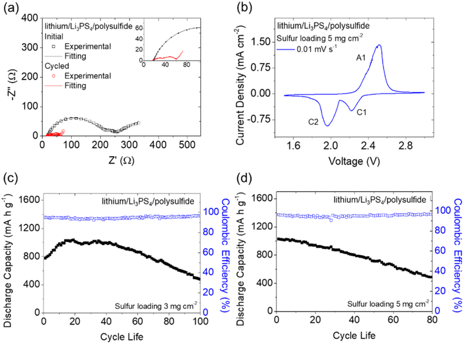 | ||
| Fig. 1 Electrochemical analysis of a lithium/Li3PS4/polysulfide cell: (a) impedance analysis before and after cycling, (b) cyclic voltammetry at 0.01 mV s−1, and cyclability test results with sulfur loadings of (c) 3 mg cm−2 and (d) 5 mg cm−2 at a C/20 rate. | ||
The cyclic voltammetry results of the lithium/Li3PS4/polysulfide cell are shown in Fig. 1(b), with one anodic peak (A1) and two cathodic peaks (C1 and C2) appearing in a 1.5–3.0 V voltage window. The redox peaks represent the oxidation of Li2S to sulfur (A1) and the reductions of sulfur to polysulfide (C1) and Li2S (C2).30 The redox conversion of the polysulfide active electrode dominated the electrochemical reactions occurring in the lithium/Li3PS4/polysulfide cell. Therefore, we continued to investigate the cycling performance and the charge/discharge behaviors of the lithium/Li3PS4/polysulfide cell. Fig. 1(c) and (d) show the cyclability test results of the lithium/Li3PS4/polysulfide cells with sulfur loadings of 3 and 5 mg cm−2 at a C/20 rate, which exhibited high peak charge storage capacities (1029 and 1026 mA h g−1) respectively. Accordingly, the strong electrochemical performance corresponded to the high areal capacities (3.1–5.1 mA h cm−2) and high energy densities (6.8–11.3 mW h cm−2), with reversible capacities of 479 and 487 mA h g−1 after cycling for 100 and 80 cycles, respectively. The initial activation process was related to the capacity increase, which may have resulted from the stabilization time of the interface between the solid electrolyte and the polysulfide cathode and the lithium anode. The good cycling performance proved that the smooth charge transfer enabled by the liquid–solid interface between the polysulfide cathode and the Li3PS4 solid electrolyte facilitated the electrochemical conversion of the active material and the enhancement of the sulfur loading and content to 5 mg cm−2 and 66 wt%, respectively. As shown in Fig. S4,† the corresponding charge/discharge curves of the lithium/Li3PS4/polysulfide cell indicate that the cells with sulfur loadings of 3 and 5 mg cm−2 both demonstrated typical charge and discharge plateaus of sulfur, which arose from the oxidation of Li2S to sulfur and the reverse reduction from sulfur to Li2S of the polysulfide cathode.31 The overlapped curves indicated the low polarization of the electrochemical reactions during cycling, with high reversibility and stability. Moreover, the only detected conversion was of sulfur, which reconfirmed that the charge storage capacity was due to the polysulfide cathode. This finding was in accordance with the cyclic voltammetry analysis results.
Investigation of the sulfide solid electrolyte–polysulfide cathode interface
Based on the excellent electrochemical performance of the lithium/Li3PS4/polysulfide cell, we performed a detailed analysis of the Li3PS4 solid electrolyte before and after cycling. This was performed to characterize the improved charge transfer and reaction reversibility provided by the liquid–solid interface between the polysulfide cathode and the Li3PS4 solid electrolyte. We first investigated the surface morphology and elemental distribution of the cathode and anode sides of both the fresh and cycled Li3PS4 solid electrolytes. The SEM images of the fresh Li3PS4 solid electrolyte (Fig. S5(a) and (c)†) show that the surfaces of the cathode and anode sides had a similarly rough morphology; however, the cathode-side surface of the cycled Li3PS4 solid electrolyte became muddy, while that of the anode side remained rough (Fig. S5(b) and (d)†). Energy dispersive spectrometry (EDS) maps of the cathode and anode sides of both the fresh and cycled Li3PS4 solid electrolyte are summarized in Fig. S6 and S7.† The sulfur and phosphorus signals overlap and show no significant differences.The morphology difference at the cathode side before and after cycling led us to investigate the cross section of the Li3PS4 solid electrolyte, with an inspection direction from the cathode side surface toward the anode side. As shown in Fig. 2 and S8(a), (c),† the cross section of the fresh electrolyte had the same morphology from the top surface to approximately 90 μm in depth at the cathode side of the interface by the focused ion beam, with strong and overlapping sulfur and phosphorus signals in the region. By comparison, the morphology of the cross section of the cycled electrolyte from the top to approximately 90 μm in depth at the cathode side changed from a muddy to a distinct appearance, with a little detected phosphorus signal at the top of the cross section, and an increased intensity of sulfur and phosphorus signals at 90 μm in depth on the cathode side (Fig. 3 and S8(b), (d)†). The fresh and cycled lithium anodes shown in Fig. S9 and S10† both exhibited low but overlapping sulfur and phosphorus signals on the lithium surface, which may have been due to the close contact with the Li3PS4 solid electrolyte. Based on the differences in the SEM and EDS results of the fresh and cycled electrolyte cross sections, we inferred that the cathode side of the Li3PS4 solid electrolyte surface interacted with the polysulfide cathode during the initial activation process. Furthermore, the lithium anode was not severely damaged, and trace sulfur was detected on the surface after cycling, indicating that the polysulfide active material did not penetrate through the solid electrolyte to reach the lithium anode surface.
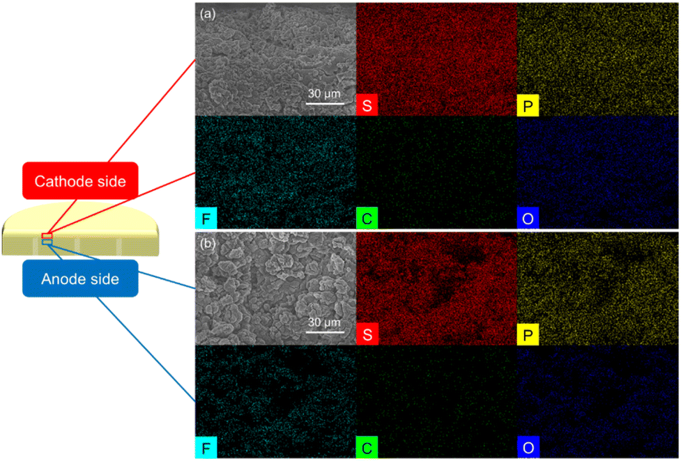 | ||
| Fig. 2 SEM/EDS results of a fresh Li3PS4 solid electrolyte cross-section: microstructure and elemental distribution (a) at the spot nearest to the cathode side and (b) at a spot approximately 90 μm in depth at the cathode side. | ||
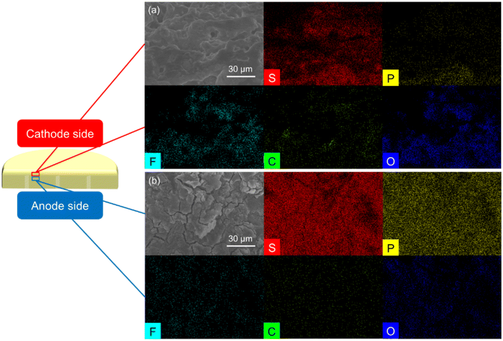 | ||
| Fig. 3 SEM/EDS results of a cycled Li3PS4 solid electrolyte cross-section: microstructure and elemental distribution (a) at the spot nearest to the cathode side and (b) at a spot approximately 90 μm in depth at the cathode side. | ||
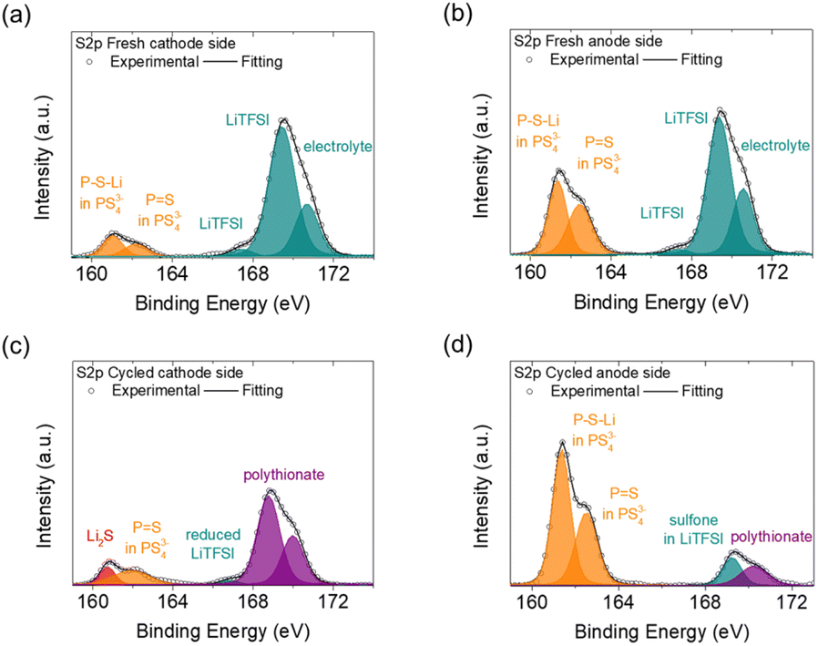
We next examined the surfaces of the cathode and anode sides of the fresh and cycled solid electrolytes by XPS, as shown in Fig. 4 and 5. In the S2p spectrum, the cathode and anode sides of the fresh electrolyte both had detections for PS43−-related bonds, including P–S–Li at 161.5 eV and P![[double bond, length as m-dash]](https://www.rsc.org/images/entities/char_e001.gif) S at 162.1 eV, which represented the ball-milled Li3PS4 solid electrolyte (Fig. 4(a) and (b)).32 The intensities of the detected PS43−-related bonds at the cathode side were weaker than those at the anode side, indicating that the cathode side of the Li3PS4 pellet might have slightly reacted during the contact with the polysulfide cathode. In addition, the cathode and anode sides of the fresh electrolyte both exhibited signals for LiTFSI salt (167.5 and 169.2 eV)33 and blank electrolyte (170.5 eV);34 these compounds resulted from the polysulfide catholyte and the lithium anode preprocessing procedures, respectively. As shown in Fig. 4(c) and (d), the cathode side of the cycled Li3PS4 solid electrolyte exhibited a weak signal for Li2S but retained a signal for PS43−-related bonds (PS), while the anode side again showed strong signals for PS43−-related bonds (P–S–Li and PS). We also observed the formation of polythionates (168.8 and 170.0 eV)35 on the cathode side of the Li3PS4 pellet (which might have been formed from side reactions of the polysulfide cathode during cycling) and only minor signals for LiTFSI (166.5 and 169.0 eV)33,36 on the cathode and anode sides. The differences in the detected intensities of PS43− for the fresh electrolyte on the cathode and anode sides and the generation of Li2S at the cathode side of the cycled electrolyte were in line with the previous SEM/EDS results, showing that the Li3PS4 solid electrolyte might have undergone some in situ chemical reactions with the polysulfide cathode at the contact surface during the earlier cycling process.
S at 162.1 eV, which represented the ball-milled Li3PS4 solid electrolyte (Fig. 4(a) and (b)).32 The intensities of the detected PS43−-related bonds at the cathode side were weaker than those at the anode side, indicating that the cathode side of the Li3PS4 pellet might have slightly reacted during the contact with the polysulfide cathode. In addition, the cathode and anode sides of the fresh electrolyte both exhibited signals for LiTFSI salt (167.5 and 169.2 eV)33 and blank electrolyte (170.5 eV);34 these compounds resulted from the polysulfide catholyte and the lithium anode preprocessing procedures, respectively. As shown in Fig. 4(c) and (d), the cathode side of the cycled Li3PS4 solid electrolyte exhibited a weak signal for Li2S but retained a signal for PS43−-related bonds (PS), while the anode side again showed strong signals for PS43−-related bonds (P–S–Li and PS). We also observed the formation of polythionates (168.8 and 170.0 eV)35 on the cathode side of the Li3PS4 pellet (which might have been formed from side reactions of the polysulfide cathode during cycling) and only minor signals for LiTFSI (166.5 and 169.0 eV)33,36 on the cathode and anode sides. The differences in the detected intensities of PS43− for the fresh electrolyte on the cathode and anode sides and the generation of Li2S at the cathode side of the cycled electrolyte were in line with the previous SEM/EDS results, showing that the Li3PS4 solid electrolyte might have undergone some in situ chemical reactions with the polysulfide cathode at the contact surface during the earlier cycling process.
 | ||
| Fig. 4 XPS S2p spectra of the Li3PS4 solid electrolyte: (a) on the cathode side and (b) on the anode side of the fresh electrolyte, and (c) on the cathode side and (d) on the anode side of the cycled electrolyte. | ||
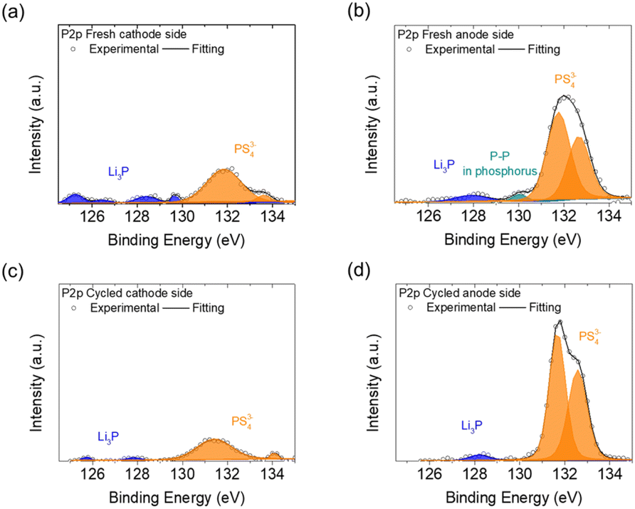 | ||
| Fig. 5 XPS P2p spectra of the Li3PS4 solid electrolyte: (a) on the cathode side and (b) on the anode side of the fresh electrolyte, and (c) on the cathode side and (d) on the anode side of the cycled electrolyte. | ||
The P2p spectra of the fresh and cycled Li3PS4 solid electrolyte (Fig. 5) showed that fewer PS43− anions were on the cathode side than on the anode side, including the detections at 131.8, 132.7, 133.4, and 134.1 eV.32,37,38 Additionally, compared with the fresh anode side, the fresh cathode side showed more characteristic peaks of Li3P at 125.0–130.0 eV, but the cycled cathode and anode sides both showed fewer of these peaks.39–43 The greater proportion of PS43− anions and the presence of Li3P on the fresh and cycled cathode sides demonstrated that the Li3PS4 solid electrolyte reacted with polysulfide after coming into contact with the polysulfide cathode to form Li3P at the surface. Li3P is an expected passivation product of sulfide solid electrolytes and is thermodynamically stable in the presence of lithium metal.44 Thus, the generation of ionically conductive Li3P might have enhanced the charge transfer at the interface between the polysulfide cathode and solid electrolyte.45 Li3P on the cathode side of the Li3PS4 pellet might have been formed from the chemical reaction between the polysulfide cathode and Li3PS4 solid electrolyte, while on the anode side it was formed from the reaction between the lithium anode and Li3PS4 solid electrolyte.44 We also examined the Li1s spectra of the cathode and anode sides of the fresh and cycled Li3PS4 solid electrolytes, as shown in Fig. S11.† The fresh cathode and anode sides of the Li3PS4 pellet mainly exhibited the characteristic peaks of the blank electrolyte, including Li–N at 54.2 eV, LiNxOy at 55.9 eV, Li–F at 56.1 eV, and Li–O bonds at 55.6 and 57.4 eV, while a peak for Li–S at 54.8 eV was found on the fresh cathode side (Fig. S11(a) and (b)†).38,46,47 After cycling, the cathode and anode sides exhibited signals for Li–O bonds (LiOH at 55.3 eV), but no signals for Li–S bonds were detected on either side (Fig. S11(c) and (d)†). The Li1s results indicate that the blank electrolyte signals represented materials from the polysulfide catholyte and the lithium anode preprocessing procedure; in addition, the absence of Li–S bonds indicated that the polysulfide did not penetrate through the Li3PS4 electrolyte pellet.
After obtaining the XPS results, we conducted depth profiling to 300 nm using TOF-SIMS on the cathode and anode sides of the fresh and cycled solid electrolytes. Four ions—LiP−, PO−, S2O−, and PS−—were the main ions detected by TOF-SIMS, as shown in Fig. 6 and 7. The LiP− and PO− signals indicated the presence of Li3P and Li3PO4, while the signals of S2O− and PS− indicated the presence of the polysulfide and Li3PS4 solid electrolyte, respectively.48 As shown in Fig. 6(a) and (b), the intensity of the LiP− signal in the fresh electrolyte was slightly higher than that in the cycled electrolyte, and the cathode sides of the fresh and cycled electrolytes both had higher-intensity LiP− signals than the anode sides. This intensity difference indicated that Li3P was formed on both the cathode and anode sides of the Li3PS4 solid electrolyte but that the cathode side generated more Li3P and Li3PO4 mixtures, which might result from the reaction of ether solvents, polysulfides, and Li3PS4 solid electrolyte during the initial passivation. Fig. 6(c) and (d) show that the cathode side of the fresh electrolyte had high-intensity signals for PO−, with an increased intensity after cycling, while the anode sides of the fresh and cycled electrolyte had similarly low-intensity signals for PO−.
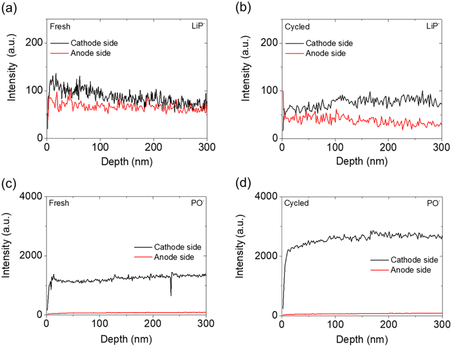 | ||
| Fig. 6 TOF-SIMS analysis of the cathode and anode sides of the Li3PS4 solid electrolyte: the detection of LiP− in (a) the fresh electrolyte and (b) the cycled electrolyte, and the detection of PO− in (c) the fresh electrolyte and (d) the cycled electrolyte. | ||
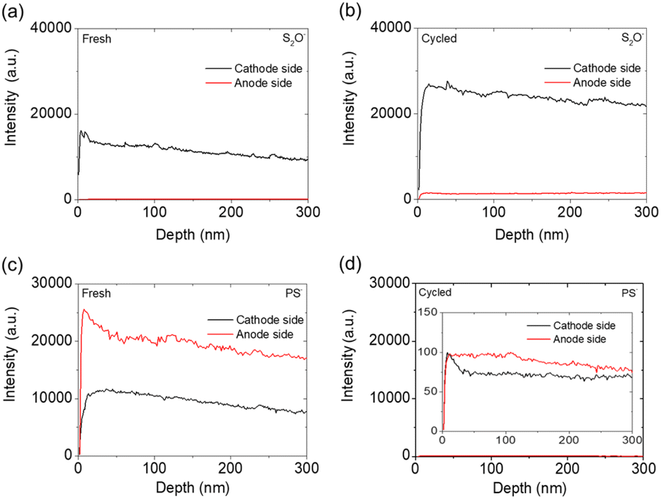 | ||
| Fig. 7 TOF-SIMS analysis of the cathode and anode sides of the Li3PS4 solid electrolyte: the detection of S2O− in (a) the fresh electrolyte and (b) the cycled electrolyte, and the detection of PS− in (c) the fresh electrolyte and (d) the cycled electrolyte (inset is 200×). | ||
The above-described LiP− and PO− signals confirmed the formation of Li3P and Li3PO4, which mainly occurred on the cathode side. Li3PO4 is an ionic conductor that has been reported to maintain high ionic conductivity and electrochemical stability of amorphous sulfide solid electrolyte materials, allowing lithium ions to transfer across the contact surface.48,49 With the formation of the ionically conductive Li3P and Li3PO4, the electrode/electrolyte interface is passivated and thus stabilized, giving rise to improved charge transfer.44,50 In addition, the contact between the polysulfide cathode and the Li3PS4 solid electrolyte might have promoted the formation of Li3P and Li3PO4 through chemical reactions instead of through electrochemical reactions that often cause cycle instability and reaction irreversibility; this idea can be inferred from previous cyclic voltammetry, charge/discharge curves, and XPS results.44 The occurrence of such chemical reactions explains how the liquid–solid interface between the polysulfide cathode and the Li3PS4 solid electrolyte promoted charge transfer and contributed to the improved electrochemical performance of the lithium/Li3PS4/polysulfide cell.
We next investigated S2O− and PS− ions (Fig. 7). Fig. 7(a) and (b) show that the intensity of S2O− signals on the cathode side of the electrolyte increased after cycling, which implies that the polysulfide active material was well retained in the cathode. Fig. 7(c) and (d) show that the overall intensity of PS− signals drastically decreased after cycling. The reduced intensity of PS− signals indicates that the Li3PS4 solid electrolyte reacted with the polysulfide cathode and lithium anode to form Li3P and Li3PO4 protective layers, respectively, during the initial chemical reaction. The chemical reaction between polysulfide and the Li3PS4 solid electrolyte promoted the formation of these materials and thus contributed to the weaker-intensity signals for PS− on the cathode side.
To sum up the TOF-SIMS analysis, detailed three-dimensional visualizations of the four ions (LiP−, PO−, S2O−, and PS−) detected on both the cathode and anode sides of the fresh and cycled Li3PS4 solid electrolytes are provided in Fig. S12–S15.† The three-dimensional visualizations of the four ions (LiP−, PO−, S2O−, and PS−) detected on both the cathode and anode sides of the fresh and cycled Li3PS4 solid electrolytes support the discussion on the surface and interface analysis collected from morphological/elemental inspection, XPS, and TOF-SIMS. The inner surface of 300 nm was analyzed and reported in plots. The LiP− and PO− shown in Fig. S12 and S13† confirm the generation of the Li3P and Li3PO4 passivation layers mainly at the cathode side and on the surface, which indicates the block of polysulfide diffusion and the stability of the protection layer. The S2O− and PS− shown in Fig. S14 and S15† affirm the high polysulfide and Li3PS4 signals in the cathode region. In consideration of the use of the Li3PS4 solid electrolyte between the two electrodes, the strong S2O− and PS− signals affirm the polysulfide cathode that is stabilized within the cathode region. This also suggested that the solid electrolyte has a stable interface facing the polysulfide cathode and the lithium anode.
Conclusions
In this study, we developed a novel cell design featuring a polysulfide cathode coupled with a sulfide solid electrolyte to form a lithium–sulfur cell. The liquid–solid interface between the cathode and electrolyte replaced the conventional solid–solid interface with the use of sulfur cathodes, thereby improving the charge-transfer path to facilitate electrochemical reactions. The highly reactive polysulfide, fast charge transfer at the interface, and ionically conductive Li3PS4 solid electrolyte enabled us to attain a high loading and content of the active material (5 mg cm−2 and 66 wt%, respectively). The advanced lithium/Li3PS4/polysulfide cell achieved a high charge storage capacity (1026 mA h g−1) with a high areal capacity (5.1 mA h cm−2), a high energy density (11.3 mW h cm−2), and a long cycle life (approaching 100 cycles). To further understand the benefits brought about by the liquid–solid interface between the polysulfide cathode and Li3PS4 solid electrolyte, we investigated the cathode and the anode sides of the electrolyte before and after cycling. XPS and TOF-SIMS confirmed that ionically conductive materials were formed during initial cycling and that these were mainly Li3P and Li3PO4 at the cathode side. The Li3P and Li3PO4 that formed through chemical reactions with polysulfide served as protective layers that prevented the full penetration of polysulfide through the Li3PS4 pellet and contributed to the improved charge transfer at the interface. Our findings illustrate a new concept for the design of solid-state lithium–sulfur batteries with high energy densities and clarify the details of the cathode–solid electrolyte interface.Conflicts of interest
There are no conflicts to declare.Acknowledgements
This work was supported by the Ministry of Education (MOE) in Taiwan under the Yushan Young Scholar Program and the National Science and Technology Council (NSTC) in Taiwan under grants 111-2636-E-006-027 and 111-2923-E-006-009. This research was supported in part by the Higher Education Sprout Project, Ministry of Education to the Headquarters of University Advancement at National Cheng Kung University (NCKU). The authors gratefully acknowledge the use of XRD005100, EM000800, and ESCA000200 of MOST 111-2731-M-006-001 belonging to the Core Facility Center of National Cheng Kung University.Notes and references
- S.-H. Chung and A. Manthiram, Adv. Mater., 2019, 31, 1901125 CrossRef PubMed.
- T. Ould Ely, D. Kamzabek, D. Chakraborty and M. F. Doherty, ACS Appl. Energy Mater., 2018, 1, 1783 CrossRef CAS.
- M. Zhao, B. Q. Li, H. J. Peng, H. Yuan, J. Y. Wei and J. Q. Huang, Angew. Chem., Int. Ed., 2020, 59, 12636 CrossRef CAS PubMed.
- J. He and A. Manthiram, Energy Storage Mater., 2019, 20, 55 CrossRef.
- L. Huang, J. Li, B. Liu, Y. Li, S. Shen, S. Deng, C. Lu, W. Zhang, Y. Xia, G. Pan, X. Wang, Q. Xiong, Q. Xia and J. Tu, Adv. Funct. Mater., 2020, 30, 1910375 CrossRef CAS.
- S.-H. Chung and A. Manthiram, ACS Appl. Mater. Interfaces, 2018, 10, 43749 CrossRef CAS PubMed.
- S.-H. Chung and A. Manthiram, Adv. Funct. Mater., 2018, 28, 1801188 CrossRef.
- J. Zhang, H. Huang, J. Bae, S.-H. Chung, W. Zhang, A. Manthiram and G. Yu, Small Methods, 2018, 2, 1700279 CrossRef.
- C. Zheng, L. Li, K. Wang, C. Wang, J. Zhang, Y. Xia, H. Huang, C. Liang, Y. Gan, X. He, X. Tao and W. Zhang, Batteries Supercaps, 2021, 4, 8 CrossRef CAS.
- J. Zhang, C. Zheng, L. Li, Y. Xia, H. Huang, Y. Gan, C. Liang, X. He, X. Tao and W. Zhang, Adv. Energy Mater., 2020, 10, 1903311 CrossRef CAS.
- C. Zheng, J. Zhang, Y. Xia, H. Huang, Y. Gan, C. Liang, X. He, X. Tao and W. Zhang, Small, 2021, 17, 2101326 CrossRef CAS PubMed.
- C. Wang, T. Yang, W. Zhang, H. Huang, Y. Gan, Y. Xia, X. He and J. Zhang, J. Mater. Chem. A, 2022, 10, 3400 RSC.
- M. Tatsumisago, M. Nagao and A. Hayashi, Journal of Asian Ceramic Societies, 2013, 1, 17 CrossRef.
- J. Lau, R. H. DeBlock, D. M. Butts, D. S. Ashby, C. S. Choi and B. S. Dunn, Adv. Energy Mater., 2018, 8, 1800933 CrossRef.
- M. Nagao, A. Hayashi and M. Tatsumisago, Electrochim. Acta, 2011, 56, 6055 CrossRef CAS.
- B. Ding, J. Wang, Z. Fan, S. Chen, Q. Lin, X. Lu, H. Dou, A. K. Nanjundan, G. Yushin, X. Zhang and Y. Yamauchi, Mater. Today, 2020, 40, 114 CrossRef CAS.
- Z. Lin, Z. Liu, N. J. Dudney and C. Liang, ACS Nano, 2013, 7, 2829 CrossRef CAS PubMed.
- M. Nagao, A. Hayashi and M. Tatsumisago, Electrochem. Commun., 2012, 22, 177 CrossRef CAS.
- Y. V. Mikhaylik and J. R. Akridge, J. Electrochem. Soc., 2004, 151, A1969 CrossRef CAS.
- T. Yamada, S. Ito, R. Omoda, T. Watanabe, Y. Aihara, M. Agostini, U. Ulissi, J. Hassoun and B. Scrosati, J. Electrochem. Soc., 2015, 162, A646 CrossRef CAS.
- H.-L. Wu, L. A. Huff and A. A. Gewirth, ACS Appl. Mater. Interfaces, 2015, 7, 1709 CrossRef CAS PubMed.
- R. Garcia-Mendez, F. Mizuno, R. Zhang, T. S. Arthur and J. Sakamoto, Electrochim. Acta, 2017, 237, 144 CrossRef CAS.
- S. A. Khan, R. W. Hughes and P. A. Reynolds, Vib. Spectrosc., 2011, 56, 241 CrossRef CAS.
- J. S. Berg, A. Schwedt, A. C. Kreutzmann, M. M. Kuypers and J. Milucka, Appl. Environ. Microbiol., 2014, 80, 629 CrossRef PubMed.
- B. Huber, L. Rossrucker, J. Sundermeyer and B. Roling, Solid State Ionics, 2013, 247, 15 CrossRef.
- J. Yan, X. Liu and B. Li, Adv. Sci., 2016, 3, 1600101 CrossRef PubMed.
- W. G. Wang, X. Wang, L. Y. Tian, Y. L. Wang and S. H. Ye, J. Mater. Chem. A, 2014, 2, 4316 RSC.
- P. P. Wang, C. Y. Xu, W. D. Li, L. Wang and L. Zhen, Electrochim. Acta, 2015, 169, 440 CrossRef CAS.
- S. B. Tang, M. O. Lai and L. Lu, Mater. Chem. Phys., 2008, 111, 149 CrossRef CAS.
- Y.-J. Yen and S.-H. Chung, Chem. Commun., 2021, 57, 2009 RSC.
- Y.-J. Yen and S.-H. Chung, ACS Appl. Mater. Interfaces, 2021, 13, 58712 CrossRef CAS PubMed.
- S. Wenzel, D. A. Weber, T. Leichtweiss, M. R. Busche, J. Sann and J. Janek, Solid State Ionics, 2016, 286, 24 CrossRef CAS.
- R. Grissa, V. Fernandez, N. Fairley, J. Hamon, N. Stephant, J. Rolland, R. Bouchet, M. Lecuyer, M. Deschamps, D. Guyomard and P. Moreau, ACS Appl. Energy Mater., 2018, 1, 5694 CAS.
- F. Yin, J. Ren, Y. Zhang, T. Tan and Z. Chen, Nanoscale Res. Lett., 2018, 13, 1 CrossRef CAS PubMed.
- L. Wang, G. R. Li, S. Liu and X. P. Gao, Adv. Funct. Mater., 2021, 31, 2010693 CrossRef CAS.
- M. I. Nandasiri, L. E. Camacho-Forero, A. M. Schwarz, V. Shutthanandan, S. Thevuthasan, P. B. Balbuena, K. T. Mueller and V. Murugesan, Chem. Mater., 2017, 29, 4728 CrossRef CAS.
- W. Brehm, A. L. Santhosha, Z. Zhang, C. Neumann, A. Turchanin, A. Martin, N. Pinna, M. Seyring, M. Rettenmayr, J. R. Buchheim and P. Adelhelm, Adv. Funct. Mater., 2020, 30, 1910583 CrossRef CAS.
- J. Liang, X. Li, Y. Zhao, L. V. Goncharova, G. Wang, K. R. Adair, C. Wang, R. Li, Y. Zhu, Y. Qian, L. Zhang, R. Yang, S. Lu and X. Sun, Adv. Mater., 2018, 30, 1804684 CrossRef PubMed.
- A. Kato, H. Kowada, M. Deguchi, C. Hotehama, A. Hayashi and M. Tatsumisago, Solid State Ionics, 2018, 322, 1 CrossRef CAS.
- B. Kwon, S. Ha, D. M. Kim, D. Koo, J. Lee and K. T. Lee, Adv. Mater. Interfaces, 2020, 7, 2001037 CrossRef CAS.
- N. Wu, Y. Li, A. Dolocan, W. Li, H. Xu, B. Xu, N. S. Grundish, Z. Cui, H. Jin and J. B. Goodenough, Adv. Funct. Mater., 2020, 30, 2000831 CrossRef CAS.
- X. Wang, C. Liu, S. Zhang, H. Wang, R. Wang, Y. Li and J. Sun, ACS Appl. Energy Mater., 2021, 4, 5246 CrossRef CAS.
- K. N. Wood, K. X. Steirer, S. E. Hafner, C. Ban, S. Santhanagopalan, S. H. Lee and G. Teeter, Nat. Commun., 2018, 9, 2490 CrossRef PubMed.
- A. Banerjee, X. Wang, C. Fang, E. A. Wu and Y. S. Meng, Chem. Rev., 2020, 120, 6878 CrossRef CAS PubMed.
- X. Wang, C. Liu, S. Zhang, H. Wang, R. Wang, Y. Li and J. Sun, ACS Appl. Energy Mater., 2021, 4, 5246 CrossRef CAS.
- S. Xiong, K. Xie, Y. Diao and X. Hong, J. Power Sources, 2014, 246, 840 CrossRef CAS.
- K. N. Wood and G. Teeter, ACS Appl. Energy Mater., 2018, 1, 4493 CrossRef CAS.
- F. Walther, S. Randau, Y. Schneider, J. Sann, M. Rohnke, F. H. Richter, W. G. Zeier and J. Janek, Chem. Mater., 2020, 32, 6123 CrossRef CAS.
- M. Tatsumisago, K. Hirai, T. Minami, K. Takada and S. Kondo, J. Ceram. Soc. Jpn., 1993, 101, 1315 CrossRef CAS.
- A. Banerjee, H. Tang, X. Wang, J. H. Cheng, H. Nguyen, M. Zhang, D. H. S. Tan, T. A. Wynn, E. A. Wu, J.-M. Doux, T. Wu, L. Ma, G. E. Sterbinsky, M. S. D'Souza, S. P. Ong and Y. S. Meng, ACS Appl. Mater. Interfaces, 2019, 11, 43138 CrossRef CAS PubMed.
Footnote |
| † Electronic supplementary information (ESI) available: XRD patterns, Raman spectra, lithium/Li3PS4/lithium symmetric cells, impedance analysis, SEM/EDS results, XPS spectra, and 3D visualization. See DOI: https://doi.org/10.1039/d2ta07806f |
| This journal is © The Royal Society of Chemistry 2023 |