
 Open Access Article
 This Open Access Article is licensed under a Creative Commons Attribution-Non Commercial 3.0 Unported Licence
Fluorosulfonamide-type electrolyte additives for long-life K-ion batteries†
Zachary T.
Gossage
 ,
Tomooki
Hosaka
,
Tatsuo
Matsuyama
,
Ryoichi
Tatara
and
Shinichi
Komaba
*
,
Tomooki
Hosaka
,
Tatsuo
Matsuyama
,
Ryoichi
Tatara
and
Shinichi
Komaba
*
Department of Applied Chemistry, Tokyo University of Science, Tokyo 162-8601, Japan. E-mail: komaba@rs.tus.ac.jp
First published on 2nd December 2022
Abstract
Graphite is a promising negative electrode material for emerging potassium ion batteries (KIBs), offering a good capacity and a low-potential discharge plateau. To date, achieving long cycle life KIBs with graphite remains limited due to the formation of an unstable solid electrolyte interphase (SEI), especially in common potassium hexafluorophosphate (KPF6) electrolytes. Herein, we show that fluorosulfonamide-type additives, such as dimethyl sulfamoyl fluoride (DMSF) or potassium bis(fluorosulfonyl)amide (KFSA), can be incorporated into KPF6 electrolytes to improve the cycling performance of graphite. In half-cells, 1 and 10 wt% added DMSF showed significant improvements in the charge/discharge coulombic efficiency (CE) and a low cell polarization. Adding DMSF to full cells (graphite‖K2Mn[Fe(CN)6]) further showed a high capacity retention of 68% after 500 cycles compared with 37% for the additive-free electrolyte. Even higher performance was observed when combining DMSF with KFSA in the same electrolyte, demonstrating a capacity retention of 85% after 500 cycles. Electrochemical impedance measurements suggested an improved charge transfer resistance in DMSF containing electrolytes. Ex situ analyses of the graphite surface indicated differences in the SEI composition for the similar structured additives. Notably, N incorporation was not observed with DMSF, but only when using KFSA, suggesting differences in degradation products and incorporation into the SEI. At the same time, computational analyses suggested similar HOMO and LUMO energy levels for the additives. This presents an opportunity to tune a portion of the fluorosulfonamide structure for further improving the SEI and KIB performance.
1. Introduction
With an increasing demand for efficient and sustainable energy storage technologies, K-ion batteries (KIBs) have emerged as promising alternatives to the dominant Li-ion battery (LIB) market.1–3 KIBs show several competitive advantages for future energy storage including highly abundant electrode materials,4 even distribution of potassium sources across the globe,5 fast ion diffusion in organic electrolytes,6 comparable voltage capabilities to LIBs,7,8 and compatibility with low-weight Al current collectors.7,9 On the path toward high-voltage and long cycle life KIBs, substantial research efforts are focused on developing improved electrode materials4,10–15 and optimization of the electrolyte.8,9,16 While significant progress has been made, more effort is still needed to maintain KIBs as a competitive alternative to LIBs.Currently, graphite is the most promising negative electrode material for commercializing KIBs with a relatively high density of 2.3 g cm−3, reasonable theoretical capacity (279 mA h g−1 for KC8vs. 372 mA h g−1 for LiC6) and similar redox potential for K+ insertion compared with Li+.1,3 Reports have already demonstrated capacities close to the theoretical value and showed opportunity for faster (de)intercalation rates compared with LIBs.7,8,12,17 However, many reports on graphite show fast capacity fading during cycling and poor first cycle irreversible capacities, especially in carbonate-based electrolytes using potassium hexafluorophosphate (KPF6).8,12,18,19 To some extent, this behavior is attributed to large volume expansion during ion insertion (59.7% for K+ compared with 10.7% for Li+) which can disrupt interphase formation.20 Our group and others showed improvements in the graphite performance and coulombic efficiencies (CEs) when using robust binders based on sodium polyacrylate (PANa) and sodium carboxymethylcellulose (CMC) for preparing the electrodes.7,21,22 In addition, improvements in the electrolyte were also shown to influence the CE and cycle stability of graphite, presumably through their influence on the solid electrolyte interphase (SEI).1,3
As graphite is charged, its electrode potential substantially decreases to potentials which can reduce commonly used organic carbonate solvents (e.g. ethylene carbonate (EC), diethyl carbonate (DEC), etc.). This leads to formation of a nanoscale film on the graphite surface, the SEI, composed of electrolyte-derived components, such as fluorides, carbonates, and polymeric structures.23,24 While the SEI is an essential and common component in high-voltage batteries, understanding and improving its complex structure still remains a difficult task in battery research.1,24–26 Multiple strategies are being explored for improving SEI chemistry including optimization of the electrolyte composition,9,27–29 electrolyte additives,16,30 and artificial SEI.31–33 Several studies have shown benefits by replacing the KPF6 electrolyte salt with potassium bis(fluorosulfonyl)amide (KFSA) or potassium bis(trifluoromethanesulfonyl) amide (KTFSA).34–37 Replacing the electrolyte could prove a successful approach, but KFSA and other alternatives tend to be significantly more expensive than conventional carbonate solvents paired with KPF6. Instead of full electrolyte replacement, an alternative step is to use SEI-modifying additives for improving the cell while maintaining a reasonable cost.16,30,38
Electrolyte additives have been extensively reported for improving LIBs,39,40 but remain limited for KIB applications. A few studies evaluated fluoroethylene carbonate additives for altering SEI chemistry and improving the cycling performance in K electrolytes, but this additive tended to increase polarization and resistance.18,19,38 Other additives, including difluoroethylene carbonate and vinylene carbonate, also negatively impacted cell polarization.41 Recently, our group reported a sulfate ester additive in K-metal cells without increased cell polarization.30 Unfortunately, such positive effects were not observed when using the same additive with graphite negative electrodes. In another recent study, we showed improved performance of graphite in KIBs when using a mixed electrolyte of KPF6 and KFSA.9 This addition of KFSA to the electrolyte led to a different interphase composition and improved the ionic conductivity, rate performance and CE for full cells using a graphite electrode. Here, we further expand on this concept to explore the impact of multiple fluorosulfonamide-type additives on graphite performance, including KFSA, dimethylsulfamoyl fluoride (DMSF) and diethylsulfamoyl fluoride (DESF), as shown in Fig. 1.
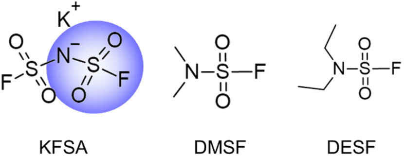 | ||
| Fig. 1 Structures of additives containing fluorosulfonamide-type functionalities. | ||
We targeted the DMSF and DESF additives based on their similar structure to the FSA− anion, which has been shown to improve the SEI structure and graphite performance in K+ electrolytes.9,34,37 Like FSA−, DMSF and DESF both contain fluorosulfonamide-type functionalities in their structure (Fig. 1), and thus, they likely contribute to the SEI in similar ways. However, the impact of varying the structure of such additives has not been explored. To date, DMSF was explored as a battery solvent in Li metal batteries,42 but it has not yet been utilized in KIBs. DESF also has not yet been applied in batteries. When using these additives at concentrations of 1 and 10 wt% in a 0.75 mol kg−1 KPF6 electrolyte, we found that DMSF was successful in improving the initial charge/discharge CE and subsequent capacity access. In contrast to other additives, DMSF improved cell performance without increasing polarization, and showed compatibility with high-voltage Prussian blue (PB) positive electrodes in graphite‖K2Mn[Fe(CN)6] full cell measurements for up to 500 cycles. Further, electrochemical impedance spectroscopy (EIS) measurements indicated a reduction in charge transfer resistance when adding DMSF to the electrolyte. Surface analysis of the graphite electrodes cycled with each additive showed notable differences in the SEI composition despite the similar additive structure.
2. Experimental methods
2.1 Electrolyte preparation and characterization
K+ electrolytes were prepared by dissolving 0.75 mol kg−1 potassium hexafluorophosphate (KPF6, Kishida Chemical) in battery grade ethylene carbonate (EC)![[thin space (1/6-em)]](https://www.rsc.org/images/entities/char_2009.gif) :diethyl carbonate (DEC) (1:1 v/v, Kishida Chemical). For evaluating the additives, the KPF6 electrolyte above was prepared with an added 1 or 10 wt% of either potassium bis(fluorosulfonyl)amide (KFSA, ≥99.9%, Solvionic), dimethylsulfamoyl fluoride (DMSF, 95%, Enamine), or diethylsulfamoyl fluoride (DESF, 95%, Enamine). All additives were used without further purification. An optimized electrolyte was also prepared using 1 mol kg−1 K(PF6)0.75(FSA)0.25 in ethylene carbonate:propylene carbonate, EC:PC (1:1 v/v, Kishida Chemical) with or without DMSF.
:diethyl carbonate (DEC) (1:1 v/v, Kishida Chemical). For evaluating the additives, the KPF6 electrolyte above was prepared with an added 1 or 10 wt% of either potassium bis(fluorosulfonyl)amide (KFSA, ≥99.9%, Solvionic), dimethylsulfamoyl fluoride (DMSF, 95%, Enamine), or diethylsulfamoyl fluoride (DESF, 95%, Enamine). All additives were used without further purification. An optimized electrolyte was also prepared using 1 mol kg−1 K(PF6)0.75(FSA)0.25 in ethylene carbonate:propylene carbonate, EC:PC (1:1 v/v, Kishida Chemical) with or without DMSF.
The ionic conductivity was characterized using a conductivity meter (TOA DK CT-58101B) in ∼2 mL volume of each electrolyte. All samples were prepared inside a glovebox. After adding the electrolyte to a test tube, the conductivity meter was attached and sealed with parafilm. The meter and sample were transferred outside the glovebox and placed in a temperature-controlled box at 25 °C and the conductivity was recorded after 2 hours. The electrolyte viscosity was analyzed using a DMA 4100 M density meter. Raman analysis of the additive-free, 10 wt% KFSA and 10 wt% DMSF electrolytes was performed using a 532 nm laser and a Raman spectrometer (Raman 11i, Nanophoton) at room temperature. The samples were sealed in a quartz tube inside a glovebox prior to analysis. The Raman shifts were normalized to the E2g band of HOPG (1581 cm−1).43
2.2 Electrode preparation
Graphite electrodes were prepared by first mixing 95 wt% graphite powder (SNO3, SEC Carbon) and 5 wt% carboxymethyl cellulose (#2200, Daicel Finechem) with a mortar and pestle. Thereafter, water was added to the mixture and it was shaken for ∼20 minutes using a planetary mixer (ARE-310, Thinky) to form a uniform slurry. The slurry was spread on Al foil using a doctor blade, dried at 80 °C, and then stored inside a glovebox under an Ar atmosphere until further use. The mass loading for the electrodes was 1.6–3 mg cm−2. The glovebox was maintained at a dew point below −80 °C.For preparation of K2Mn[Fe(CN)6] (Mn-PB) positive electrodes, the active material was synthesized according to previous reports.8 Mn-PB, Ketjen black (EC600JD, Carbon ECP, Lion) and polytetrafluoroethylene (F-104, Daikin) powders were manually mixed in the mass ratio 7:2:1 using a mortar and pestle until a uniform mass was acquired. Thereafter, the mixture was flattened and cut into 10 mm discs. The composite electrode discs were placed on top of Al mesh current collectors and pressed between two pieces of Al foil at 20 MPa for approximately 5 minutes. The electrodes were stored inside a glovebox until further use.
For K metal counter electrodes, a piece of K metal was taken from storage under kerosene, dried and cut to remove the surface layers on all sides. The piece of fresh metal was placed inside a plastic bag containing DEC and flattened. Discs were cut from the flattened K metal sheet to act as the counter electrodes for half-cell measurements. The same procedure was applied for preparing K metal reference electrodes, except that the fresh K metal was cut into small strips and pressed into a ring shape.
2.3 Electrochemical measurements
All cycling measurements were conducted using a TOSCAT-3100 charge–discharge test system (Toyo System). Half and full cells were assembled using 2032 coin-type cells. For the half-cells, we used a graphite negative electrode and a K metal counter electrode with a glass fiber separator (GB-100R, Advantec). For full cells, we used a graphite negative electrode and a Mn-PB positive electrode separated by a polyolefin separator (Toray). The mass loading ratio of negative and positive electrodes was maintained at ∼1:2.1 (N:P). To prevent corrosion, an Al foil disc was placed between the K2Mn[Fe(CN)6] and stainless steel cap. All half and full cells were assembled and allowed to equilibrate for 24 hours before cycling. For rate testing, a VMP3 multichannel potentiostat (Biologic) and a three-electrode cell (Toyo System) were used with separate K counter and reference electrodes. Before the start of the rate test, a low current (8 μA cm−2) was applied to the K reference and counter electrodes in 8 hour steps to ensure a fresh K surface.41 For electrochemical impedance spectroscopy (EIS) measurements, we again used the same setup as our rate tests. After precycling the K reference and counter electrodes, the graphite electrode was cycled between 2 and 0 V vs. K and then charged again to 0 V. EIS data were collected at open circuit using a 5 mV amplitude and frequencies between 1 mHz and 1 MHz. Data were fit using an equivalent circuit model similar to previous reports44 and ZView 4. All electrochemical cells were assembled inside an Ar-filled glovebox with a dew point lower than −80 °C.
2.4 Surface analysis
For analyzing the SEI structure, full cells were cycled for 10 charge–discharge cycles at a C-rate of 0.1C, i.e. a calculated charge/discharge time of 10 hours based on the theoretical capacity of K+ insertion into graphite (279 mA h g−1). After finishing the final discharge, the cells were quickly transferred to a glovebox for disassembly. The graphite electrodes were dipped in diethyl carbonate several times and allowed to dry in the glovebox. The samples were cut and attached to a metal stage inside a glovebox and transferred through the air for energy-dispersive X-ray spectroscopy (EDS) analysis and imaging using a scanning electron microscope (SEM; JCM-6000, JEOL Ltd.). X-ray photoelectron spectra (XPS) measurements were conducted at room temperature using an X-ray photoelectron spectrometer (JPS 9010MC, JEOL Ltd.) with non-monochromatic Mg Kα radiation (1253 eV) using a voltage of 12 kV and emission current of 10 mA. The samples were mounted on the XPS stage inside a glovebox, and then placed inside a sealed, Ar-filled container for transport to the XPS instrument. The samples were quickly transferred through air to the XPS vacuum chamber and vacuumed overnight before analysis. The XPS spectra were calibrated using the sp2 C binding energy for graphite at 284.4 eV.45 For hard X-ray photoelectron spectroscopy (HAXPES), the electrodes were cycled for 3 charge–discharge cycles, then disassembled and prepared in the same manner as the XPS samples. The HAXPES analysis was acquired using a high excitation energy of 7939 eV and a photoelectron energy analyzer of R-4000 (Scienta Omicron) at BL46XU at SPring-8, Japan. A photoelectron detection angle of 80° and analyzer pass energy of 200 eV were used. Further details on HAXPES measurements are described in our previous reports.46,472.5 Additive analysis with gas chromatography/mass spectrometry
DESF purity was qualitatively analyzed using gas chromatography/mass spectrometry with a GCMS-QP2020 NX (Shimadzu). The samples were diluted 1:10 in acetonitrile (99.5%). A mid-polar SH-Rtx-200 (30 m × 0.25 mm × 0.25 μm) column was used with He (G1 grade, >99.99995 vol%) as the carrier gas at a linear velocity of 48 cm s−1. The temperature of the column was held at 40 °C for 3 min then ramped at a rate of 7 °C min−1 up to 100 °C, and then increased at a rate of 12 °C min−1 up to 280 °C. Thereafter, the final temperature was held for 8 min. The mass range was 20–600 m/z and the event time was 0.3 s in scan mode. Ionization was performed using electron ionization (EI). Using the same GC/MS methods, we evaluated the degradation of each electrolyte after contact with a piece of K metal for ∼10 days.
2.6 Simulations
The highest occupied molecular orbitals and lowest unoccupied molecular orbitals were calculated using Gaussian 09W, version 9.5. The structure was optimized using DFT with the B3LYP functional and 6-31G(d,p) basis set. We utilized the default polarizable continuum model with integral equation formalism variant (IEFPCM) and acetonitrile for the solvation model.3. Results and discussion
3.1 Half-cell and rate testing of fluorosulfonamide-type additives
To explore the impact of fluorosulfonamide-type additives on graphite performance, we compared graphite‖K metal half-cells using electrolytes containing 0.75 mol kg−1 KPF6 in EC:DEC with and without 10 wt% of KFSA, DMSF or DESF. Electrolyte characterization, including ionic conductivity and viscosity, are provided in the ESI document (Table S1†). Starting from their open-circuit potential, the graphite electrodes were electrochemically reduced (charged) in each cell to 0 V vs. K and then cycled between 2.0 and 0 V at a rate of 0.1C.9,48 In the first cycle (Fig. 2a), we observed initial discharge capacities of approximately 240 mA h g−1 and a plateau at ∼0.3 V vs. K during discharge in line with previous results.9 However, there were notable differences in the first-cycle curves and CE among the cells. In the additive-free electrolyte, we observed an average first-cycle CE of 81% (n = 3), while 10 wt% KFSA showed an improved first-cycle CE of 87% (n = 3) (Fig. 2a and b). For DMSF, the average first-cycle CE was also slightly improved over the KPF6 cells, but the addition of DESF led to a very low first-cycle CE of 64%. We believe that the poor charge–discharge behavior for the DESF additive could be related to an impurity in the as-purchased DESF sample (rated at 95% pure). Through gas chromatography/mass spectrometry analysis of the DESF source material, we observed an eluted peak that indicated trichloromethane content as an impurity in the sample (Fig. S1†). This peak was not observed for the DMSF additive (Fig. S2†).
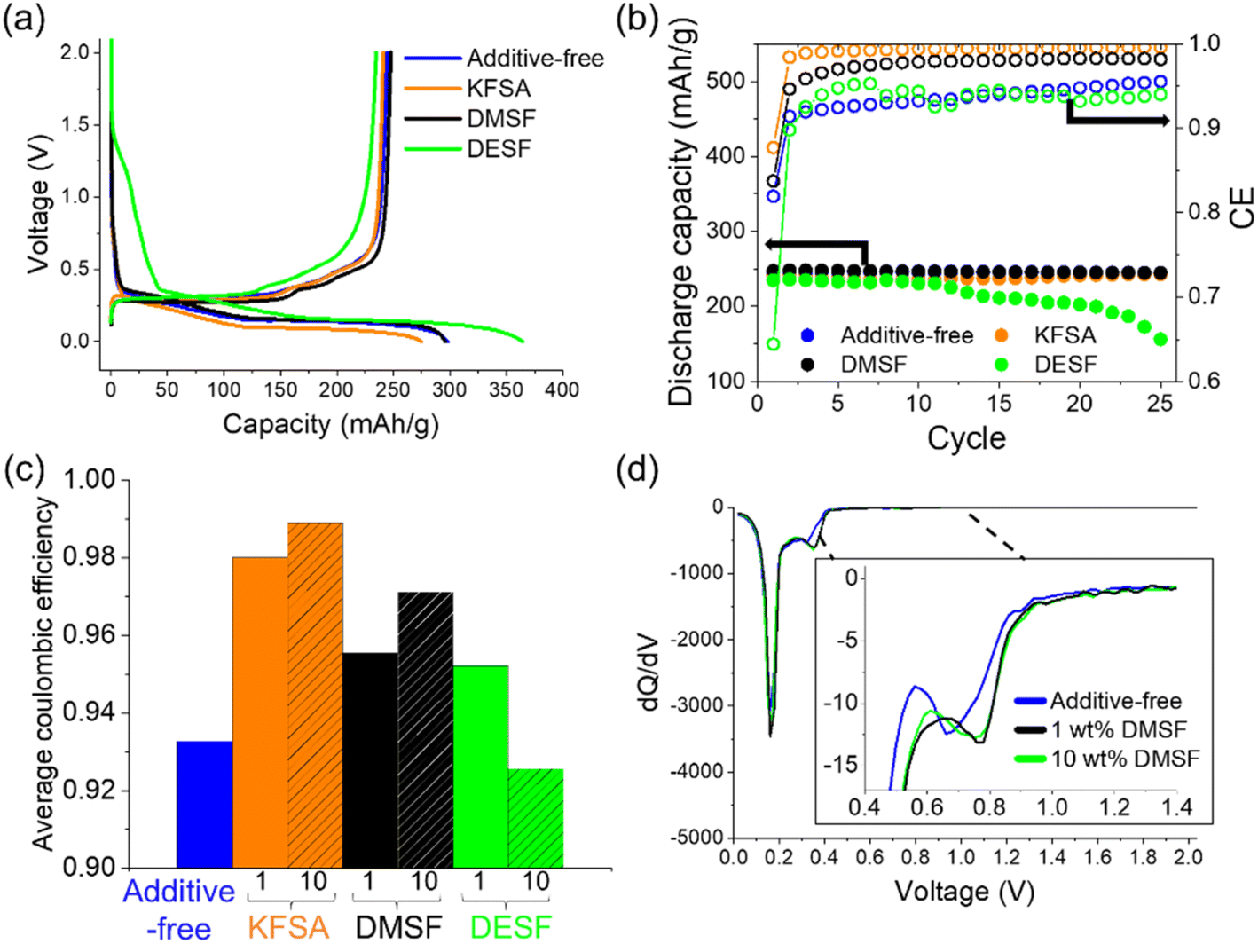 | ||
| Fig. 2 Half-cell cycling with fluorosulfonamide additives. (a) 1st cycle charge–discharge curves and (b) extracted results after further cycling at 0.1C in a graphite‖K cell with 10 wt% additives. (c) Comparison of average CEs with 1 and 10 wt% additives. (d) Differential capacity curves of the first charge for cells that were additive-free or contained 1 and 10 wt% DMSF. | ||
With further cycling, the additive-free cell, KFSA and DMSF cells continued to show stable discharge capacities, while DESF showed unstable cycling behavior with a gradual increase in polarization (Fig. 2b and S3†). The additive-free cell's CE slowly improved to ∼96% by the 25th cycle. On the other hand, adding 10 wt% KFSA or DMSF resulted in a rapid increase in CE to >98% by the second and 10th cycles, respectively. Some of the benefits gained with KFSA may be due to the accompanied increase in the electrolyte concentration, as we previously reported when adding KFSA to a KPF6 electrolyte.9 Raman analysis of the electrolytes indicated that EC-solubilization of K+ was improved with the addition of KFSA (Fig. S4†),49,50 and the ionic conductivity was increased (Table S1†). However, for the DMSF and DESF additives, the ionic conductivity was decreased compared with the additive-free electrolyte. Their Raman spectra did not suggest a major impact on K+-solvation (Fig. S4†). We also note that the electrolyte viscosity of KPF6 in EC:DEC was increased by the addition of KFSA and decreased when adding DMSF or DESF. Though increased viscosity can lower ionic conductivity and transport in electrolyte solutions,51 this was not observed for our additive-containing electrolytes. The improved CE suggests a more stable interphase for KFSA and DMSF-added electrolytes,52 while DESF appeared to disrupt the interphase stability. If the SEI was unstable and undergoing dissolution or incompletely formed, we would expect continued electrolyte decomposition throughout the charge and discharge process leading to a low CE, as observed in the DESF and additive-free cells.1,35,53 Despite the similarity between DMSF and DESF, differences in their decomposition products may lead to distinct SEI makeups which could alter the performance and stability. A similar case is observed for EC and PC with their electrochemical decomposition resulting in unique decomposition products.24
Next, we further explored each of the additives at 1 wt% addition under the same cycling conditions in graphite‖K metal half-cells. Electrolyte additives have been explored across a wide range of concentrations with different effects on battery performance.16,30,54 For all the additives, we again observed discharge capacities of >240 mA h g−1 (Fig. S5†) and improvements in the average CE (Fig. 2c). For KFSA, the average CE was similar at ∼99% for both 1 and 10 wt%. When using 1 wt% DMSF, we observed an average CE of ∼95%, compared to >97% for 10 wt% DMSF. Using 1 wt% DESF led to an improved CE and cycling performance compared with the additive-free cell. Overall, our results show promise for utilizing small amounts of 1 wt% or less to sufficiently alter the SEI chemistry and improve the overall performance of the cell.
Interestingly, when comparing the differential capacity (dQ/dV) curves for the first cycle of the 1 and 10 wt% DMSF cells (Fig. 2d), we found that they showed almost identical electrochemistry (Fig. 2d, inset). For easier comparison, we aligned the curves based on the peaks for intercalation; we note that a reference electrode was not used so the exact potentials could show some variation between the cells caused by a different cell polarization. For the dQ/dV curve of the DMSF cell, we observed a peak that initiated at more positive potentials compared to the additive-free cell. These peaks disappeared in the second cycle highlighting them as irreversible, SEI-type reactions (Fig. S6†). Likewise, we observed similar dQ/dV curves for the KFSA cells at 1 or 10 wt% (Fig. S7a†) that were in agreement with higher KFSA concentrations.9 The differential capacity curves for DESF were not very distinct from those of the additive-free electrolyte (Fig. S7b†). The peak occurring at more positive potentials for the additives is likely due to the easier decomposition of their fluorosulfonyl moiety, e.g. the F–S bond, that occurs prior to reduction of KPF6 and the EC:DEC solvent.55 Apart from the interphase chemistry, the dQ/dV curves looked similar in the intercalation region among all the cells suggesting that all the graphite electrodes undergo similar reactions with K+ ions after formation of their unique SEI.
Next, we examined the impact of 10 wt% DMSF and KFSA on rate performance using a three-electrode setup with a graphite working electrode, a K metal counter electrode, and a separate, pre-cycled K metal electrode as the reference.41 The DESF additive was not evaluated due to its poor performance in the cycling measurements as described already. The graphite electrode was again cycled between 0 and 2.0 V vs. K. The charging rate was gradually increased every 5 cycles from 0.1C up to 1C, while the discharge rate was maintained at 0.1C throughout the measurement. As with our cycling measurements, we observed an improved CE for the DMSF and KFSA additives (Fig. S8†), and modest improvements in capacity access up to a rate of 0.5C (Fig. S9†) in line with concentrated KFSA electrolytes.8,37 On the other hand, the cell polarization was notably increased when using the KFSA additive (Fig. 3). At 0.1C, the polarization between all three cells was comparable, but as the rate was increased polarization became more significant in the KFSA cell (Fig. 3b). The increased polarization may be related to a difference in the properties of the SEI formed with 10 wt% KFSA.56 The addition of DMSF to the cell did not lead to any notable increase in polarization and was comparable to the KPF6 cell at rates up to 1C. From a practical standpoint, it is important for additives to improve cell performance (e.g. CE, capacity access and retention, and resistance) to maintain good energy efficiencies within a device.
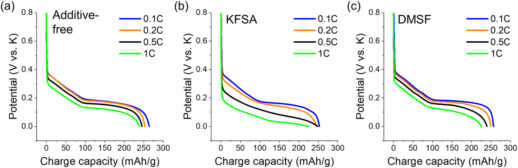 | ||
| Fig. 3 Charge curves at different rates for (a) additive-free, (b) 10 wt% added KFSA and (c) 10 wt% added DMSF. Curves shown are the results for the 5th charging cycle at each rate. | ||
3.2 Full cell measurements
In actual KIBs, the additive will also interact with high potential, positive electrodes, and therefore its oxidative stability/interphase forming characteristics at positive potentials become critical for practical usage. To investigate the additive stability in full cells, we paired graphite with positive electrodes based on the manganese Prussian blue analog, K2Mn[Fe(CN)6] (Mn-PB). Mn-PB is a promising, low-cost cathode material for high-voltage KIBs.8,9 We prepared the cells using an active material mass ratio of approximately 2.1:1 (positive:negative), corresponding to a capacity ratio of ∼1.05:1. We again used 0.75 mol kg−1 KPF6 in EC:DEC with or without 10 wt% of each additive for the electrolytes. All cells were cycled at a rate of 0.1C for charge and discharge. As seen in the first cycle charge–discharge curves (Fig. 4a), the cells delivered average discharge voltages of ∼3.45 V in the voltage range of 2.0–4.25 V. As with the half-cells, 10 wt% of KFSA and DMSF showed high first cycle CEs of 72% and 70%, respectively. On the other hand, the additive-free (61%) and DESF (51%) cells showed much lower CEs. In further cycles (Fig. 4b), KFSA, DMSF and additive-free cells showed significant improvements in their CE, approaching 98% by the 5th cycle. The CE for the DESF cell also improved but remained below 96% across 10 cycles. Despite these improvements in the CE, the impact of the first cycle was already apparent where the additive-free and DESF cells showed relatively low discharge capacities near 230 and 200 mA h g−1, respectively, in contrast to the cells containing KFSA (>255 mA h g−1) and DMSF (>250 mA h g−1). Further, the DMSF cell displayed the lowest polarization during charge and discharge (Fig. S10†). These results clearly indicate the amenability between the flurosulfonamide additives with not only the graphite electrode, but also the Mn-PB positive electrode.
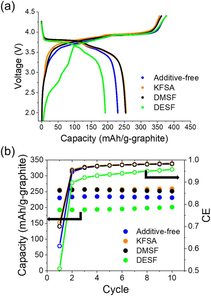 | ||
| Fig. 4 Full cell cycling with 10 wt% fluorosulfonamide additives. (a) First charge–discharge curves at 0.1C. (b) Extracted discharge capacities and CE for cells during cycling. | ||
Due to the promising results with the DMSF additive, we further evaluated its impact on performance during extended cycling. We found that the improved CE attained when using DMSF led to a higher discharge capacity across 100 cycles at 0.1C compared with the additive-free KPF6 electrolyte (Fig. S11†). Though the overall performance was improved, the capacity retention at this low rate was not significant compared to the additive-free cell. This suggests that the SEI could still be undergoing some dissolution or DMSF oxidation at the cathode may be occurring. We did observe notable oxidation of DMSF at high additive concentrations of 40–50% (Fig. S12†). Looking further, we evaluated the DMSF additive during cycling at a faster rate of 1C, again in a full cell configuration (Fig. 5). In this case, the cell was initially cycled at a 0.1C rate for 5 cycles to stabilize the SEI, and thereafter, the rate was increased to 1C for the remaining cycles (Fig. S13†). As with our other measurements, we observed an improved average CE of 99.73%, compared to 99.23% for the additive-free cell across 500 cycles (Fig. 5a). As seen in Fig. 5b, the capacity retention was also significantly improved to an average capacity of 153.8 mA h g−1 compared to the additive-free electrolyte (102.7 mA h g−1). This ∼50% improvement across a long cycling-time is quite promising for attaining long-life KIBs.
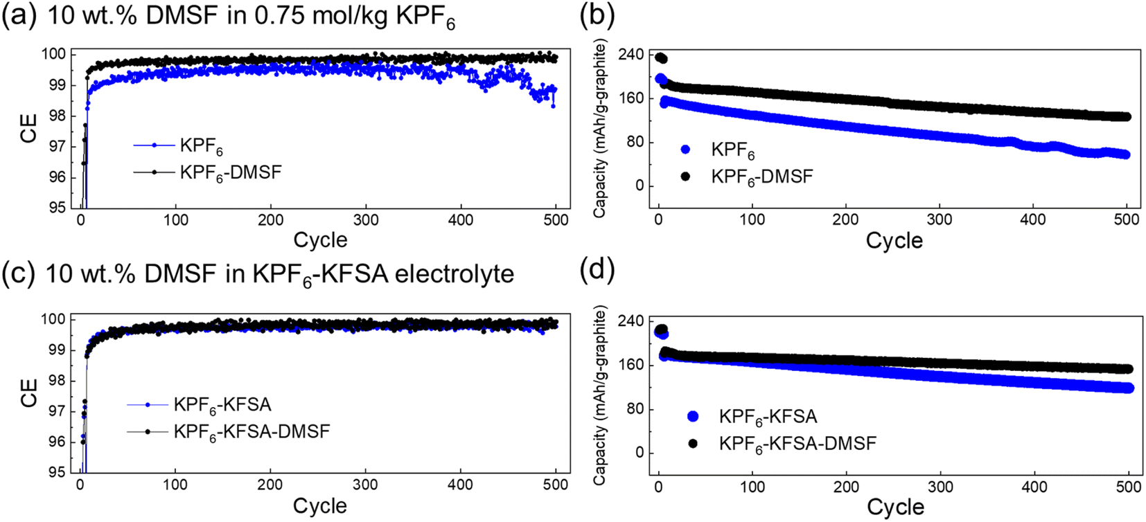 | ||
| Fig. 5 Extended cycling performance of graphite‖Mn-PB cells with 10 wt% DMSF. (a) CE and (b) extracted discharge capacities for cells cycled in 0.75 mol kg−1 KPF6 in EC:DEC with or without 10 wt% DMSF at 1C. (c) CE and (d) extracted discharge capacities for cells cycled in an optimized KFSA–KPF6 mixed electrolyte9 with or without 10 wt% DMSF at 1C. | ||
Considering the benefits of adding KFSA observed here and in our previous work,9 we evaluated the impact of using the DMSF and KFSA additives combined in the same cell. We utilized an optimized electrolyte based on 1 mol kg−1 K(PF6)0.75(FSA)0.25 in EC:PC (ethylene carbonate:propylene carbonate, 1:1 v/v), i.e. ∼19 wt% KFSA, which tended to show high performance in full cells.9 Again, the cells were initially cycled at a 0.1C rate for 5 cycles to stabilize their SEI, before the rate was increased to 1C (Fig. S14†). As seen in Fig. 5c and d, the optimized electrolyte containing KPF6–KFSA improved performance for both cells with or without DMSF compared to using the KPF6 electrolyte in EC:DEC. However, with further addition of DMSF to the optimized electrolyte, we found major improvements in the performance of the cell. Compared with the 10 wt% DMSF and the optimized electrolyte alone, the combination of both in the optimized electrolyte led to a further improved polarization at 1C. The capacity retention was successfully improved to 82.4% after 500 cycles compared to only 65.4% for the cell without DMSF. These results indicate independent benefits from DMSF and KFSA on cell performance and potential for using DMSF additives in other optimized electrolytes.
To further investigate the origin of the improved performance, we used a three-electrode configuration to evaluate the electrochemical impedance spectroscopy (EIS) of the cycled graphite electrodes. After 2–3 cycles at 0.1C charge/discharge rate, the graphite electrodes were fully reduced to 0 V and allowed to briefly rest for equilibration, then the EIS was collected at open circuit (typically ∼200 mV vs. K). Less resistive charge transfer was observed when using 10 wt% DMSF in both the KPF6/EC:DEC and optimized KPF6/KFSA/EC:PC compared with 10 wt% KFSA and additive-free electrolytes (Fig. S15†). By evaluating the charge-transfer resistance (Rct) and SEI resistance (RSEI) using an equivalent circuit model (Fig. S16†),44 we found that the optimized electrolyte with DMSF showed the lowest Rct followed by DMSF in KPF6 in EC:DEC (Table S2†). RSEI tended to show relatively high error for our fittings, but suggested RSEI was the lowest for 10 wt% DMSF and the highest for 10 wt% KFSA. Clearly, the DMSF additive can improve the charge-transfer properties for the graphite electrode. Despite the similar structures of DMSF and KFSA, their precise role and resulting impact in the cell appear to be unique. We suspect that this is related to their decomposition chemistry and incorporation of byproducts into the SEI.
3.3 Surface analysis and simulations
To further understand how the DMSF and KFSA additives were able to impact cycling performance, we turned to surface analysis of the cycled electrodes using the KPF6 electrolyte in EC:DEC with 10 wt% of each additive. It is well-known that the electrolyte composition can impact the formation and properties of the SEI.1,57–59 To avoid possible alteration of the SEI by the presence of K metal,60 we utilized graphite‖Mn-PB full cells. After 10 cycles at 0.1C, we quickly disassembled the cells inside a glovebox, rinsed the graphite electrodes using fresh DEC and allowed them to dry in the glovebox. For SEM analysis (Fig. 6), we attached the samples to the SEM stage inside the glovebox then transferred the samples through air to the SEM instrument. As seen in Fig. 6a, the SEM images indicated the bulk electrode structure did not change considerably after cycling with each of the additives compared to an unused electrode (Fig. S17†). Further SEM images at lower magnification are provided in the ESI (Fig. S18 and S19†). Thereafter, we used energy-dispersive X-ray spectroscopy (EDS) to identify elements derived from the electrolyte additives that were incorporated into the electrode surface layer. We observed F peaks (0.67 keV) for all the samples (Fig. 6b), which can originate from either the fluorosulfonamide structure or the PF6− anion. For S (2.3 keV), we observed a strong peak for the KFSA sample, but no notable peaks for the DMSF or DESF samples (Fig. 6b). Based on the similar electrolyte content of S for each of the additives, i.e., 2.9, 2.5 and 2.1 wt% for FSA−, DMSF and DESF, respectively, we would expect similar content in the SEI if they were undergoing the same decomposition reactions. Though these results are qualitative, they suggest a difference in the decomposition products of each of the additives deposited on the electrode surface. We did not observe a N peak for any of the samples, but light elements tend to produce a weak signal with common EDS detectors. Also, EDS further confirmed the presence of Cl in the DESF added electrolyte (Fig. S20†), which originated from an apparent trichloromethane impurity contained in the commercial DESF reagent (Fig. S1†).
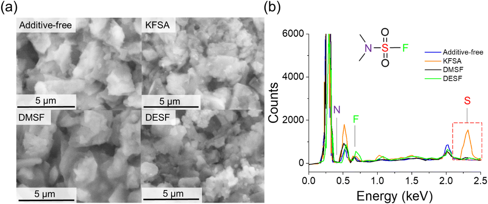 | ||
| Fig. 6 SEM and EDS measurements on cycled graphite electrodes. (a) SEM images of graphite electrodes after 10 cycles in cells containing 10 wt% of each additive. (b) EDS results of each cell. | ||
To further investigate the surface structure, we used XPS analysis of the same samples. For comparison, all the peaks were aligned based on the peak for sp2 carbon (284.4 eV), which also showed good alignment for the K 2p peaks of each sample (Fig. S21†). For the C 1s region (Fig. 7a–c and S22†), we observed multiple overlapping peaks that showed some differences among each sample. In general, the spectra could be deconvoluted to peaks located at binding energies of approximately 284.4, 285, 285.9, 286.8, and 288.8 eV, assigned to graphite (sp2 C), hydrocarbons, alcohols/ethers, carbonyl/potassium carboxylate, and ester/carboxylate, respectively.45,61,62 In the C 1s region, we also note an additional peak at approximately 283 eV that was previously reported as a K–C interaction, such as plated or residual intercalated K.16,62 While the graphite peak was dominant in all the cells, the other peaks are likely derived from solvent, electrolyte and additive decomposition reactions. For the additive-free cell, we observed significant organic content relative to the graphite peak including high hydrocarbon and potassium carboxylate content (Fig. 7a). The KFSA sample showed smaller relative amounts of organic moieties that deconvoluted to hydrocarbons, ester/carboxylate and ether/alcohol species. Previous reports suggest greater amounts of C content in the SEI for graphite and other anodes when cycled in additive-free KPF6 electrolytes compared with cycling in KFSA.9,36 Interestingly, the graphite electrode cycled with DMSF also showed large relative amounts of C species with a significant carbonyl/potassium carboxylate peak (Fig. 7c). The XPS results for the DESF cell were similar to those of the KFSA cell with a relatively dominant sp2 C peak suggesting a thin SEI or low relative organic content (Fig. S22†).
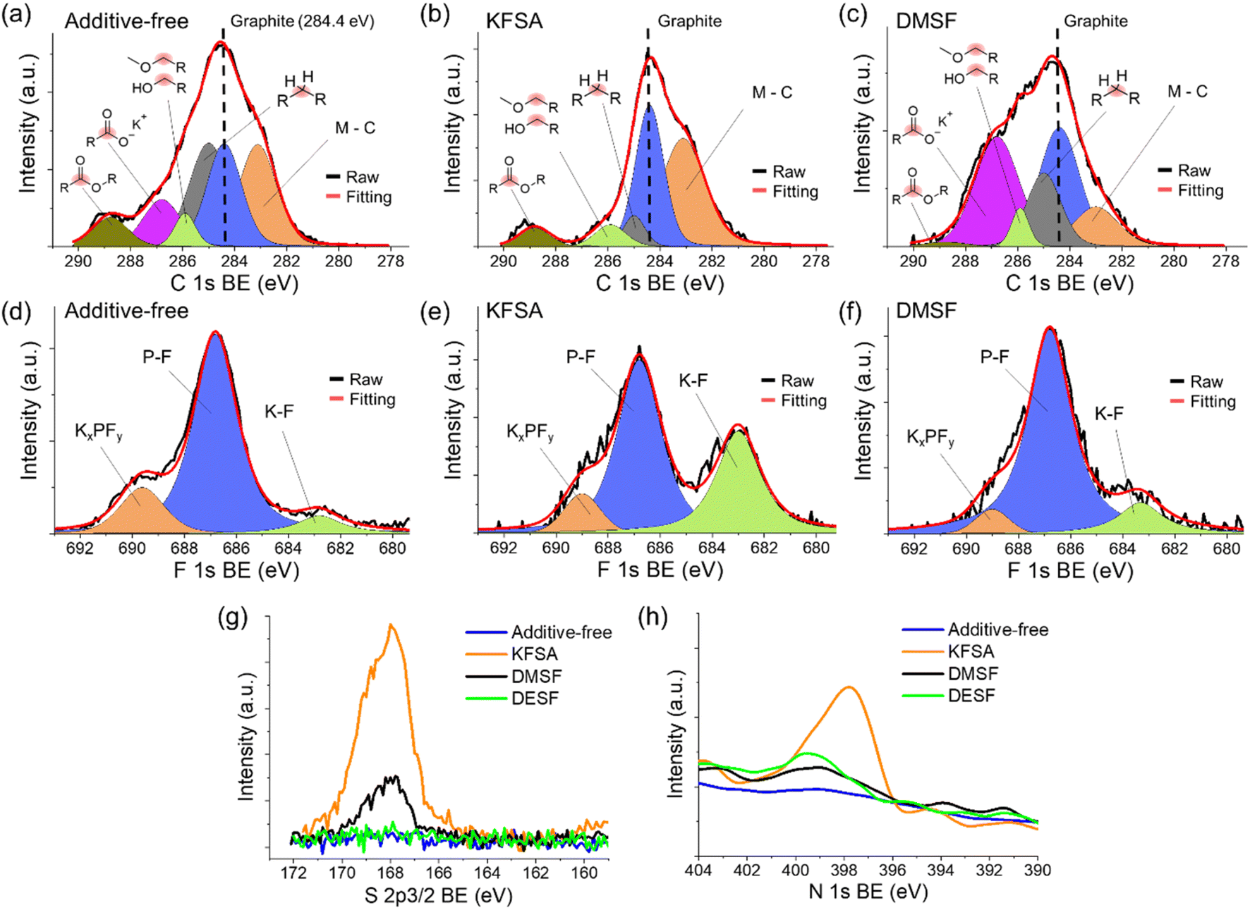 | ||
| Fig. 7 XPS analysis of cycled graphite electrodes. Deconvoluted C 1s spectra for (a) additive-free, (b) 10 wt% KFSA and (c) 10 wt% DMSF cells. Deconvoluted F 1s spectra for (d) additive-free, (e) 10 wt% KFSA and (f) 10 wt% DMSF cells. (g) Comparison of the S 2p3/2 region. (h) Comparison of the N 1s region. For the N 1s spectrum, the data were smoothed due to the low signal-to-noise. | ||
Looking at the deconvoluted F 1s region for each of the samples (Fig. 7d–f and S23†), we observed peaks indicative of KF (∼683 eV), electrolyte peaks (∼687 eV), and KxPFy or organic fluorides (∼689.5 eV).62,63 The main peak for all the samples, PF at 687 eV, can be attributed to residual electrolyte or its oxidized product. In addition, KFSA showed the largest, relative peak area for KF compared to the other cells. KF is a well-known SEI component that has been reported in KPF6 and KFSA cells,57 though its content tends to be relatively low for the SEI formed in an additive-free, KPF6 electrolyte.36 The role of KF and its criticality toward stable SEI performance remains poorly understood. It has been argued that KF presents insulative characteristics with high chemical stability and low solubility in carbonate solvents,34,36,64,65 but other studies suggest that KF leads to high interfacial cell resistance and poor ion transfer from the bulk-electrolyte to the electrode.66,67 If we normalize the data based on the C 1s region for all samples or alternatively with the P–F peak in the same region, we would observe a much lower relative content of KF in our DMSF, DESF and additive-free samples compared to the KFSA sample. Though this is not quantitative and we cannot rule out possible loss of the material from the surface due to dissolution processes during rinsing,62 the analysis suggests differences in the building of the SEI composition which likely plays a role in the observed improvements in performance. This agrees well with our cycling results that show FSA− and DMSF, despite their similar structure, uniquely impact performance. We further postulate that high KF content may not be critical to negative electrode performance in KIBs66 as its role is likely shared with other SEI components and grain boundaries.68
Apart from the C and F regions, we observed notable peaks for the KFSA and DMSF samples in the S 2p3/2 region (Fig. 7g), while no peak was observed in the case of DESF. These peaks are associated with moieties including –SOxF, –SO2–, –S(![[double bond, length as m-dash]](https://www.rsc.org/images/entities/char_e001.gif) O)–, and elemental S.69,70 S structures found in the SEI are derived from the fluorosulfonamide structure, further suggesting their decomposition at the graphite surface and potential influence on the improved cycling performance as others have suggested.9,35,36 The N 1s region also suggested differences in the decomposition of each additive, where a N peak was only observed for the KFSA additive (Fig. 7h). We did not observe significant N content for the DMSF or DESF samples using XPS (Fig. 7h). Differences in decomposition of DMSF and DESF may lead to the formation of products that are soluble in the electrolyte or gaseous. The results of GC/MS analysis of reactions of DESF and DMSF with K metal showed additional peaks in the chromatogram that matched N-containing structures (Fig. S24 and S25†). Overall, the XPS results highly suggest significant differences in the SEI composition due to the impact of each of the additives with small changes in the additive structures leading to different surface reactions and incorporation into the SEI.
O)–, and elemental S.69,70 S structures found in the SEI are derived from the fluorosulfonamide structure, further suggesting their decomposition at the graphite surface and potential influence on the improved cycling performance as others have suggested.9,35,36 The N 1s region also suggested differences in the decomposition of each additive, where a N peak was only observed for the KFSA additive (Fig. 7h). We did not observe significant N content for the DMSF or DESF samples using XPS (Fig. 7h). Differences in decomposition of DMSF and DESF may lead to the formation of products that are soluble in the electrolyte or gaseous. The results of GC/MS analysis of reactions of DESF and DMSF with K metal showed additional peaks in the chromatogram that matched N-containing structures (Fig. S24 and S25†). Overall, the XPS results highly suggest significant differences in the SEI composition due to the impact of each of the additives with small changes in the additive structures leading to different surface reactions and incorporation into the SEI.
While XPS analyzes only a few nm into the electrode surface structure, other methods can be used to evaluate deeper into the SEI. The use of an ion beam to etch the SEI to collect depth profiling has recently been applied for evaluating the SEI of KPF6 and KFSA electrolytes.71 Alternatively, hard X-ray photoelectron spectroscopy (HAXPES) using higher energy X-rays can be applied for surface analysis at depths >10 nm.61,72 Here, we utilized HAXPES measurements to further evaluate the surface structure of electrodes cycled with DMSF. The photoelectron intensities were again aligned to the sp2 C peak at 284.4 eV. In the C 1s HAXPES spectrum (Fig. S26†) for the DMSF sample, we further observed a variety of C structures similar to the XPS measurements. Deconvolution of the additive-free cell showed fewer peaks and more extensive coverage by carbonyl/potassium carboxylates species compared with the DMSF additive. These data suggest the formation of a thinner SEI when adding DMSF to the electrolyte like previous reports with KFSA.9,35 In line with a previous study using depth profiling, our HAXPES results show that the additive-free KPF6 electrolyte leads to a high content of alkyl carbonates while adding DMSF reduces the alkyl carbonate content toward ester-type structures and a thinner SEI.71 For the N 1s region of the HAXPES analysis, we again did not observe notable N content in the HAXPES spectrum for cells containing DMSF (Fig. S27†); though a clear S peak was observed (Fig. S28†). This S peak was not observed when the electrode was left soaking in the DMSF electrolyte; therefore, the observed S peak is derived from electrochemical decomposition and deposition on the graphite electrode. Altogether, the HAXPES analysis confirmed an altered SEI composition when adding DMSF and suggests a decomposition process that does not lead to incorporation of the N-group into the SEI structure.
Lastly, we applied density functional theory (DFT) calculations to gain insight into the stability and reactivity of the fluorosulfonamide-type additives. For this, we used Gaussian 09W with the B3LYP functional and 6-31G(d,p) basis set to optimize the structures and calculate the HOMO and LUMO of the additives (DMSF, DESF, FSA−), electrolyte (PF6−), and solvent (EC and DEC) species. For all simulations, we evaluated the isolated molecules using acetonitrile as the solvation model. As shown in Fig. 8a, our calculations indicated that all three additives had similar LUMO and HOMO energies with DMSF showing the lowest LUMO and HOMO. For all the additives, the LUMO energy was at a lower energy level than the solvent and PF6− anion, suggesting that they would preferentially undergo reduction at the graphite surface prior to the solvent and electrolyte. However, we emphasize that the LUMO energy does not necessarily define the reduction potential and other effects might not be captured by our model.73,74 These results are in-line with our dQ − dV analyses and evidences the likely impact of each additive on formation of the SEI initial structure and properties. The LUMO molecular orbitals (Fig. 8b, c and S29†) indicated reduction occurring around the S atom, while the HOMO orbitals (Fig. S30†) suggest oxidation at N for all of the additives. When considering the SEI formation process, a wide variety of decomposition reactions can occur with some of the reactions resulting in products that incorporate into the SEI. At the same time, additive decomposition could result in highly soluble or gaseous products that do not incorporate into to the SEI. While decomposition of the fluorosulfonyl moiety may result in similar SEI components (e.g. KF, SOxF, etc.), the N-containing portion of each additive is unique and could decompose to different products for each additive. In the case of FSA−, we observed incorporation of N-containing species in the SEI. For DMSF and DESF, the N-containing decomposition products may be soluble species that dissolve back into the electrolyte which are not observed with surface analyses. This poses some opportunities for future studies to tune the N side of the fluorosulfonamide-structure to change the resulting products during formation of the SEI. By influencing the components at the surface, the SEI structure likely could be altered for improved stability and performance.
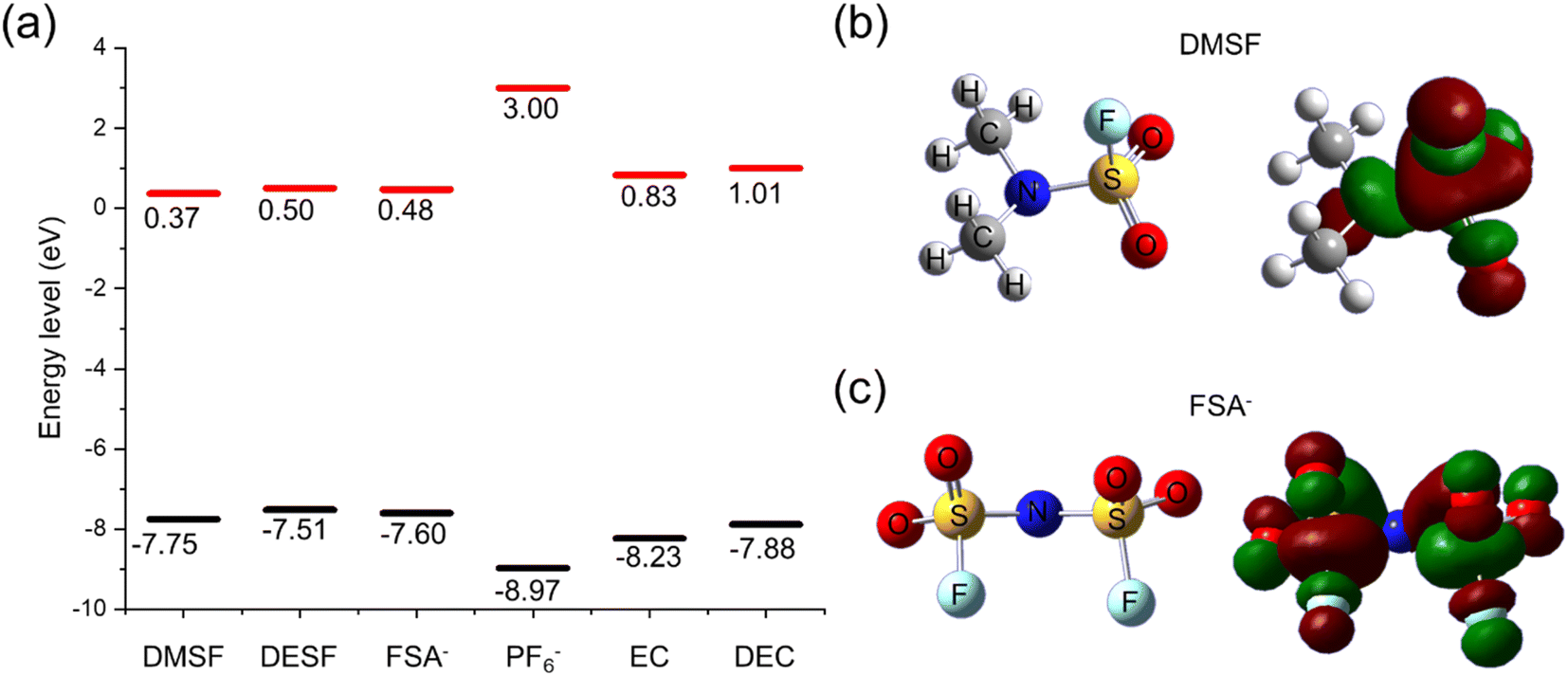 | ||
| Fig. 8 Computational analysis of the electrolyte additives. (a) Calculated LUMO (red) and HOMO (black) for the additives (DMSF, DESF, and FSA−), electrolyte (PF6−), and solvent (EC and DEC) species. Visualization of the LUMO molecular orbitals for (b) DMSF and (c) FSA− using an isovalue of 0.04. | ||
4. Conclusions
In this work, we investigated the effects of fluorosulfonamide-type additives for improving graphite performance in a KPF6 electrolyte. We found that adding 1 or 10 wt% of KFSA or DMSF to a KPF6/EC:DEC electrolyte could improve the CE and discharge capacities compared with additive-free cells. Specifically, the DMSF additive improved the CE, discharge capacity and cell polarization at rates up to 1C. Full cell measurements pairing graphite with a Mn-PB positive electrode further showed that incorporating the KFSA and DMSF additives led to improved overall performance compared with additive-free cells. Adding DMSF at 10 wt% improved the cell capacity retention to 68% after 500 cycles compared to 37% for the additive-free cell. Further, adding DMSF and KFSA to the same cell led to an even higher capacity retention of 82.4% and a high CE. EIS measurements suggested that the DMSF-added electrolytes result in an SEI showing improved charge transfer resistances compared to electrolytes without DMSF. The results of surface analysis using XPS and EDS revealed differences in the electrolyte decomposition products for each of the additives despite their similar structures. Specifically, the DMSF additive resulted in a graphite surface containing greater relative organic species, S moieties, but no notable N content, while analysis of the SEI formed with KFSA showed lower relative organic content and N incorporation. DESF did not show N or S incorporation. Overall, our findings suggest a wide degree of tunability for electrolyte additives which can show diverse degradation reactions and incorporation into the SEI depending on the additive structure. Building on the benefits gained from the KFSA structure, further modification of the N-group as seen with DMSF and DESF may lead to similar additives with improved properties.75 Through the use of low weight additions of various additives, it was possible to improve the cycling characteristics of the K-ion cell even in a poor electrolyte system, such as KPF6 in EC:DEC.
Author contributions
Z. T. G. conducted most of the experiments, simulations and wrote the manuscript. T. M. and T. H. conducted full cell measurements for this publication. HAXPES measurements were conducted by R. T. Analyses of the data and writing of the manuscript included contributions by all authors. All authors have given approval to the final version of the manuscript.Conflicts of interest
There are no conflicts to declare.Acknowledgements
HAXPES measurements were performed at the BL46XU of SPring-8 as the Priority Research Proposal (priority field: Industrial Application) with the approval of the Japan Synchrotron Radiation Research Institute (JASRI) (Proposal No. 2021B1874). The authors thank Dr Satoshi Yasuno for the experimental assistance with the HAXPES measurements. This study was partially funded by the MEXT program “ESICB” (Grant No. JPMXP0112101003), JST through the A-STEP program (Grant No. JPMJTS1611), CREST (Grant No. JPMJCR21O6), and JSPS KAKENHI (Grant No. JP20J13077, JP20H02849, JP21K14724, and JP21K20561).Notes and references
- T. Hosaka, K. Kubota, A. S. Hameed and S. Komaba, Chem. Rev., 2020, 120, 6358–6466 CrossRef CAS PubMed.
- W. Zhang, Y. Liu and Z. Guo, Sci. Adv., 2019, 5, eaav7412 CrossRef CAS PubMed.
- S. Dhir, S. Wheeler, I. Capone and M. Pasta, Chem, 2020, 6, 2442–2460 CAS.
- E. J. Kim, P. R. Kumar, Z. T. Gossage, K. Kubota, T. Hosaka, R. Tatara and S. Komaba, Chem. Sci., 2022, 13, 6121–6158 RSC.
- D. Larcher and J.-M. Tarascon, Nat. Chem., 2015, 7, 19–29 CrossRef CAS PubMed.
- T. A. Pham, K. E. Kweon, A. Samanta, V. Lordi and J. E. Pask, J. Phys. Chem. C, 2017, 121, 21913–21920 CrossRef CAS.
- S. Komaba, T. Hasegawa, M. Dahbi and K. Kubota, Electrochem. Commun., 2015, 60, 172–175 CrossRef CAS.
- T. Hosaka, K. Kubota, H. Kojima and S. Komaba, Chem. Commun., 2018, 54, 8387–8390 RSC.
- T. Hosaka, T. Matsuyama, K. Kubota, S. Yasuno and S. Komaba, ACS Appl. Mater. Interfaces, 2020, 12, 34873–34881 CrossRef CAS PubMed.
- X. Wang, S. Tang, W. Guo, Y. Fu and A. Manthiram, Mater. Today, 2021, 50, 259–275 CrossRef CAS.
- Q. Xie, H. Ou, Q. Yang, X. Lin, A. Zeb, K. Li, X. Chen and G. Ma, Dalton Trans., 2021, 50, 9669–9684 RSC.
- Z. Jian, W. Luo and X. Ji, J. Am. Chem. Soc., 2015, 137, 11566–11569 CrossRef CAS PubMed.
- L. Xue, Y. Li, H. Gao, W. Zhou, X. Lü, W. Kaveevivitchai, A. Manthiram and J. B. Goodenough, J. Am. Chem. Soc., 2017, 139, 2164–2167 CrossRef CAS PubMed.
- T. Masese, K. Yoshii, Y. Yamaguchi, T. Okumura, Z.-D. Huang, M. Kato, K. Kubota, J. Furutani, Y. Orikasa and H. Senoh, Nat. Commun., 2018, 9, 1–12 CrossRef CAS PubMed.
- A. Kamiyama, K. Kubota, T. Nakano, S. Fujimura, S. Shiraishi, H. Tsukada and S. Komaba, ACS Appl. Energy Mater., 2019, 3, 135–140 CrossRef.
- H. Yang, C.-Y. Chen, J. Hwang, K. Kubota, K. Matsumoto and R. Hagiwara, ACS Appl. Mater. Interfaces, 2020, 12, 36168–36176 CrossRef CAS PubMed.
- Z. Wang, A. P. Ratvik, T. Grande and S. M. Selbach, RSC Adv., 2015, 5, 15985–15992 RSC.
- X. Bie, K. Kubota, T. Hosaka, K. Chihara and S. Komaba, J. Mater. Chem. A, 2017, 5, 4325–4330 RSC.
- J. Liao, Q. Hu, Y. Yu, H. Wang, Z. Tang, Z. Wen and C. Chen, J. Mater. Chem. A, 2017, 5, 19017–19024 RSC.
- J. Zhao, X. Zou, Y. Zhu, Y. Xu and C. Wang, Adv. Funct. Mater., 2016, 26, 8103–8110 CrossRef CAS.
- K. Beltrop, S. Beuker, A. Heckmann, M. Winter and T. Placke, Energy Environ. Sci., 2017, 10, 2090–2094 RSC.
- D. Igarashi, K. Kubota, T. Hosaka, R. Tatara, T. Inose, Y. Ito, H. Inoue, M. Takeuchi and S. Komaba, Electrochemistry, 2021, 89, 433–438 CrossRef CAS.
- E. Peled and S. Menkin, J. Electrochem. Soc., 2017, 164, A1703 CrossRef CAS.
- S. J. An, J. Li, C. Daniel, D. Mohanty, S. Nagpure and D. L. Wood III, Carbon, 2016, 105, 52–76 CrossRef CAS.
- J. Hui, Z. T. Gossage, D. Sarbapalli, K. Hernandez-Burgos and J. Rodríguez-López, Anal. Chem., 2018, 91, 60–83 CrossRef PubMed.
- A. M. Tripathi, W.-N. Su and B. J. Hwang, Chem. Soc. Rev., 2018, 47, 736–851 RSC.
- J. Zhang, Z. Cao, L. Zhou, G. Liu, G.-T. Park, L. Cavallo, L. Wang, H. N. Alshareef, Y.-K. Sun and J. Ming, ACS Energy Lett., 2020, 5, 2651–2661 CrossRef CAS.
- L. Wang, J. Yang, J. Li, T. Chen, S. Chen, Z. Wu, J. Qiu, B. Wang, P. Gao and X. Niu, J. Power Sources, 2019, 409, 24–30 CrossRef CAS.
- M. Fiore, S. Wheeler, K. Hurlbutt, I. Capone, J. Fawdon, R. Ruffo and M. Pasta, Chem. Mater., 2020, 32, 7653–7661 CrossRef CAS.
- T. Hosaka, T. Fukabori, T. Matsuyama, R. Tatara, K. Kubota and S. Komaba, ACS Energy Lett., 2021, 6, 3643–3649 CrossRef CAS.
- J. Hui, N. B. Schorr, S. Pakhira, Z. Qu, J. L. Mendoza-Cortes and J. Rodríguez-López, J. Am. Chem. Soc., 2018, 140, 13599–13603 CrossRef CAS PubMed.
- H. Wang, J. Hu, J. Dong, K. C. Lau, L. Qin, Y. Lei, B. Li, D. Zhai, Y. Wu and F. Kang, Adv. Energy Mater., 2019, 9, 1902697 CrossRef CAS.
- X. Zheng, H. Fu, C. Hu, H. Xu, Y. Huang, J. Wen, H. Sun, W. Luo and Y. Huang, J. Phys. Chem. Lett., 2019, 10, 707–714 CrossRef CAS PubMed.
- W. Zhang, W. K. Pang, V. Sencadas and Z. Guo, Joule, 2018, 2, 1534–1547 CrossRef CAS.
- Q. Zhang, J. Mao, W. K. Pang, T. Zheng, V. Sencadas, Y. Chen, Y. Liu and Z. Guo, Adv. Energy Mater., 2018, 8, 1703288 CrossRef.
- L. Deng, Y. Zhang, R. Wang, M. Feng, X. Niu, L. Tan and Y. Zhu, ACS Appl. Mater. Interfaces, 2019, 11, 22449–22456 CrossRef CAS PubMed.
- L. Fan, S. Chen, R. Ma, J. Wang, L. Wang, Q. Zhang, E. Zhang, Z. Liu and B. Lu, Small, 2018, 14, 1801806 CrossRef PubMed.
- S. U. Yoon, H. Kim, H.-J. Jin and Y. S. Yun, Appl. Surf. Sci., 2021, 547, 149193 CrossRef CAS.
- H. Zhang, G. G. Eshetu, X. Judez, C. Li, L. M. Rodriguez-Martínez and M. Armand, Angew. Chem., Int. Ed., 2018, 57, 15002–15027 CrossRef CAS PubMed.
- S. S. Zhang, J. Power Sources, 2006, 162, 1379–1394 CrossRef CAS.
- T. Hosaka, S. Muratsubaki, K. Kubota, H. Onuma and S. Komaba, J. Phys. Chem. Lett., 2019, 10, 3296–3300 CrossRef CAS PubMed.
- W. Xue, Z. Shi, M. Huang, S. Feng, C. Wang, F. Wang, J. Lopez, B. Qiao, G. Xu and W. Zhang, Energy Environ. Sci., 2020, 13, 212–220 RSC.
- Y. Kawashima and G. Katagiri, Phys. Rev. B: Condens. Matter Mater. Phys., 1995, 52, 10053 CrossRef CAS PubMed.
- M. Goktas, C. Bolli, J. Buchheim, E. J. Berg, P. Novák, F. Bonilla, T. f. Rojo, S. Komaba, K. Kubota and P. Adelhelm, ACS Appl. Mater. Interfaces, 2019, 11, 32844–32855 CrossRef CAS PubMed.
- R. I. R. Blyth, H. Buqa, F. P. Netzer, M. G. Ramsey, J. O. Besenhard, P. Golob and M. Winter, Appl. Surf. Sci., 2000, 167, 99–106 CrossRef CAS.
- N. Yabuuchi, K. Shimomura, Y. Shimbe, T. Ozeki, J. Y. Son, H. Oji, Y. Katayama, T. Miura and S. Komaba, Adv. Energy Mater., 2011, 1, 759–765 CrossRef CAS.
- M. Dahbi, T. Nakano, N. Yabuuchi, S. Fujimura, K. Chihara, K. Kubota, J. Y. Son, Y. T. Cui, H. Oji and S. Komaba, ChemElectroChem, 2016, 3, 1856–1867 CrossRef CAS.
- D. Wang, X. Du and B. Zhang, Small Struct., 2022, 2200078 CrossRef CAS.
- M. Shimizu, T. Koya, A. Nakahigashi, N. Urakami, T. Yamakami and S. Arai, J. Phys. Chem. C, 2020, 124, 13008–13016 CrossRef CAS.
- H. Wang, D. Yu, X. Wang, Z. Niu, M. Chen, L. Cheng, W. Zhou and L. Guo, Angew. Chem., 2019, 131, 16603–16607 CrossRef.
- J. L. Barton, J. D. Milshtein, J. J. Hinricher and F. R. Brushett, J. Power Sources, 2018, 399, 133–143 CrossRef CAS.
- J. Xie, J. Li, W. Zhuo and W. Mai, Mater. Today Adv., 2020, 6, 100035 CrossRef.
- B. Li, J. Zhao, Z. Zhang, C. Zhao, P. Sun, P. Bai, J. Yang, Z. Zhou and Y. Xu, Adv. Funct. Mater., 2019, 29, 1807137 Search PubMed.
- R. Verma, P. N. Didwal, J. Y. Hwang and C. J. Park, Batteries Supercaps, 2021, 4, 1428–1450 CrossRef CAS.
- L. Fan, K. Lin, J. Wang, R. Ma and B. Lu, Adv. Mater., 2018, 30, 1800804 CrossRef PubMed.
- J. Touja, V. Gabaudan, F. Farina, S. Cavaliere, L. Caracciolo, L. Madec, H. Martinez, A. Boulaoued, J. Wallenstein and P. Johansson, Electrochim. Acta, 2020, 362, 137125 CrossRef CAS.
- H. Wang, D. Zhai and F. Kang, Energy Environ. Sci., 2020, 13, 4583–4608 RSC.
- P. Verma, P. Maire and P. Novák, Electrochim. Acta, 2010, 55, 6332–6341 CrossRef CAS.
- Y. Zeng, Z. T. Gossage, D. Sarbapalli, J. Hui and J. Rodríguez-López, ChemElectroChem, 2022, 9, e202101445 CAS.
- L. Madec, V. Gabaudan, G. Gachot, L. Stievano, L. Monconduit and H. Martinez, ACS Appl. Mater. Interfaces, 2018, 10, 34116–34122 CrossRef CAS PubMed.
- N. Yabuuchi, Y. Matsuura, T. Ishikawa, S. Kuze, J. Y. Son, Y. T. Cui, H. Oji and S. Komaba, ChemElectroChem, 2014, 1, 580–589 CrossRef.
- A. J. Naylor, M. Carboni, M. Valvo and R. Younesi, ACS Appl. Mater. Interfaces, 2019, 11, 45636–45645 CrossRef CAS PubMed.
- M. Xu, L. Zhou, L. Hao, L. Xing, W. Li and B. L. Lucht, J. Power Sources, 2011, 196, 6794–6801 CrossRef CAS.
- N. Peruzzi, B. W. Ninham, P. Lo Nostro and P. Baglioni, J. Phys. Chem. B, 2012, 116, 14398–14405 CrossRef CAS PubMed.
- N. Peruzzi, P. Lo Nostro, B. W. Ninham and P. Baglioni, J. Solution Chem., 2015, 44, 1224–1239 CrossRef CAS.
- A. W. Ells, R. May and L. E. Marbella, ACS Appl. Mater. Interfaces, 2021, 13, 53841–53849 CrossRef CAS PubMed.
- Y. Zhang, C. Liu, Z. Wu, D. Manaig, D. J. Freschi, Z. Wang and J. Liu, ACS Appl. Mater. Interfaces, 2021, 13, 16345–16354 CrossRef CAS PubMed.
- J. Tan, J. Matz, P. Dong, J. Shen and M. Ye, Adv. Energy Mater., 2021, 11, 2100046 CrossRef CAS.
- Y. Yamada, K. Furukawa, K. Sodeyama, K. Kikuchi, M. Yaegashi, Y. Tateyama and A. Yamada, J. Am. Chem. Soc., 2014, 136, 5039–5046 CrossRef CAS PubMed.
- Y. Uchimoto, E. Endo, K. Yasuda, Y. Yamasaki, Z. i. Takehara, Z. Ogumi and O. Kitao, J. Electrochem. Soc., 2000, 147, 111 CrossRef CAS.
- H. Wang, H. Wang, S. Chen, B. Zhang, G. Yang, P. Gao, J. Liu, X. Fan, Y. Huang and J. Lin, ACS Appl. Energy Mater., 2019, 2, 7942–7951 CrossRef CAS.
- K. Kobayashi, Nucl. Instrum. Methods Phys. Res., Sect. A, 2009, 601, 32–47 CrossRef CAS.
- O. Borodin, M. Olguin, C. Spear, K. Leiter, J. Knap, G. Yushin, A. Childs and K. Xu, ECS Trans., 2015, 69, 113 CrossRef CAS.
- P. Peljo and H. H. Girault, Energy Environ. Sci., 2018, 11, 2306–2309 RSC.
- K. S. Jiang, G. M. Hobold, R. Guo, K.-H. Kim, A. M. Melemed, D. Wang, L. Zuin and B. M. Gallant, ACS Energy Lett., 2022, 7, 3378–3385 CrossRef CAS.
Footnote |
| † Electronic supplementary information (ESI) available. See DOI: https://doi.org/10.1039/d2ta06926a |
| This journal is © The Royal Society of Chemistry 2023 |