
3D fibrous aerogels from 1D polymer nanofibers for energy and environmental applications
Guodong
Zhao
ab,
Lei
Shi
b,
Guang
Yang
 b,
Xupin
Zhuang
*ab and
Bowen
Cheng
*c
b,
Xupin
Zhuang
*ab and
Bowen
Cheng
*c
aState Key Laboratory of Separation Membranes and Membrane Processes, Tiangong University, Tianjin 300387, P. R. China
bSchool of Textile Science and Engineering, Tiangong University, Tianjin 300387, P. R. China. E-mail: zhxupin@tiangong.edu.cn
cTianjin University of Science & Technology, Tianjin 300222, P. R. China. E-mail: bowen15@tiangong.edu.cn
First published on 19th December 2022
Abstract
Aerogels are highly porous structures produced by replacing the liquid solvent of a gel with air without causing the collapse of the solid network. Recently, 1D polymer nanofibers have been widely researched as building blocks to develop a new species of 3D fibrous aerogels with a physically entangled and/or chemically crosslinked fibrous network. 3D fibrous aerogels not only hold intrinsic aerogel properties such as an open-cell pore structure, low density, high specific surface area, and large porosity, but also benefit from the inherent features of polymer nanofibers including excellent mechanical flexibility and toughness, a wide range of material selection, and additional functionality. In this review, recent research progress in the fabrication and application of 3D fibrous aerogels is systematically summarized. Relevant strategies for constructing 3D fibrous aerogels, including electrospinning, solution blow spinning, freeze-drying, thermally induced self-agglomeration, and carbonization, are presented. Typical applications in energy (e.g., pressure sensors, triboelectric nanogenerators, electromagnetic interference shielding, etc.) and the environment (e.g., air filtration, thermal insulation, interfacial solar vapor generation, etc.) are highlighted. Finally, challenges in the fabrication of 3D fibrous aerogels, limitations for their use, and trends for future developments are discussed.
1. Introduction
Aerogels are commonly described as high surface area substances that are nanostructured (mostly mesoporous with a few micropores) and consist of a porous solid network.1,2 Generally, aerogels are gels in which the liquid is supplanted by gas while the pores and networks are well preserved.2 A special drying technique is used to remove the liquid in gels and avoids apparent volume shrinkage.3 The resultant aerogels exhibit a mainly air-containing three-dimensional (3D) structure with many unique characteristics, including ultralow bulk density (<0.5 g cm−3), high surface area (>50 m2 g−1), large porosity (>85%), and thermal-insulating properties, widely applied in many fields like sensors, energy storage, catalysis, and biomedical scaffolds for tissue engineering.4–7The origin of aerogels dates back to 1931 when Kistler reported on the replacement of the liquid in inorganic/organic gels by gas with negligible shrinkage using a supercritical-drying process.8 This original work did not pay much attention to aerogels until the 1980s when silica aerogels found practical use as Cherenkov detectors in particle accelerators and superinsulators in double-pane windows.9 Since then, more researchers have tried to assemble crystalline nanoparticles (e.g., oxides, metal sulfides, carbon materials, etc.) into macroscopic porous 3D networks by a sol–gel chemistry process, followed by a supercritical-drying or freeze-drying process,6,10 which endows aerogels with tunable morphologies and enlarge application properties of aerogels.11,12 Brock's group first reported nanoparticle aerogels by assembling metal chalcogenide nanocrystals into 3D networks via the partial removal of coating ligands on the nanoparticles.13 Afterwards, various metal chalcogenide, metal, and metal oxide nanoparticle-based aerogels have also been prepared by controllable destabilization of the corresponding concentrated nanoparticle suspensions.14,15 This approach of assembling preformed nanoparticles into aerogels has made it possible to control the compositions and structures of aerogels by tuning the compositions, sizes and morphologies of primary nanobuilding blocks and by engineering the gel structures. However, most of the aerogels were produced by using zero-dimensional (0D) spherical nanoparticles as building blocks and the weak interparticle force throughout the nanoparticle networks made the resultant aerogels too fragile to be integrated into a practical device without destroying their structural integrity.15
In this decade, to address the fragility of the aerogels based on 0D nanoparticles, large efforts have been made to develop aerogels using one-dimensional (1D) anisotropic nanostructures with high aspect ratios such as polymer nanofibers as building blocks.16–18 Nanofibers, as a typical 1D nanostructured material, have been concerned in recent years due to their good mechanical flexibility, with remarkable tolerance against mechanical bending and exceptionally low flexural rigidities. Apart from excellent mechanical flexibility and toughness, nanofibers also have the characteristics of a high possibility of surface functionalization, a large surface area, a wide range of material selection and tunable porosity, overcoming the inherent property limitations of conventional active materials.19,20 Based on the above advantages, 1D polymer nanofibers have been extensively researched as building blocks to develop a new species of 3D fibrous aerogels with a physically entangled and/or chemically crosslinked fibrous network, unlike the interconnected framework constructed by colloidal particles in inorganic aerogels. The “necks” do not exist in the skeletons of 3D fibrous aerogels, which can considerably avoid stress concentration and show mechanical and flexible behavior. 1D polymer nanofiber-assembled 3D fibrous aerogels exhibit many attractive properties including low density, high specific area, large porosity, and tunable pore size on varied length scales.21,22 Also, the high continuity and open-cell fibrous networks can allow excellent access of fluids, such as low transport limitations for gases and liquids. Therefore, this unique combination of properties makes 1D polymer nanofiber-assembled 3D fibrous aerogel structures highly interesting in the fields of energy and environmental applications.
Given the rapid progress in this field, a complete overview of the structuring of aerogels should be desirably reported. However, nanoparticle-based aerogels composed of semiconductors, metals and metal oxides have already been reviewed somewhere else,14,15 and also aerogels based on inorganic nanowires have recently been discussed.10 Therefore, this review aims to focus on fibrous aerogels from 1D polymer nanofibers, because they offer complementary properties like mechanical stability. We emphasize the structural design concepts and controllable synthesis strategies of 3D fibrous aerogels, which mainly include electrospinning, solution blow spinning, freeze-drying, thermally induced self-agglomeration, and carbonization. We systematically highlight the multifunctional applications of 3D fibrous aerogels in various fields, involving energy (e.g., pressure sensors, triboelectric nanogenerators, supercapacitors, electromagnetic interference shielding, etc.) and the environment (e.g., air filtration, thermal insulation, oil–water separation, interfacial solar vapor generation, etc.) (Fig. 1). Finally, the challenges and future opportunities of 3D fibrous aerogels are described. We hope that this review illustrates different strategies to design, fabricate, and use 3D fibrous aerogels for specific applications and inspires researchers to tackle future challenges in this area.
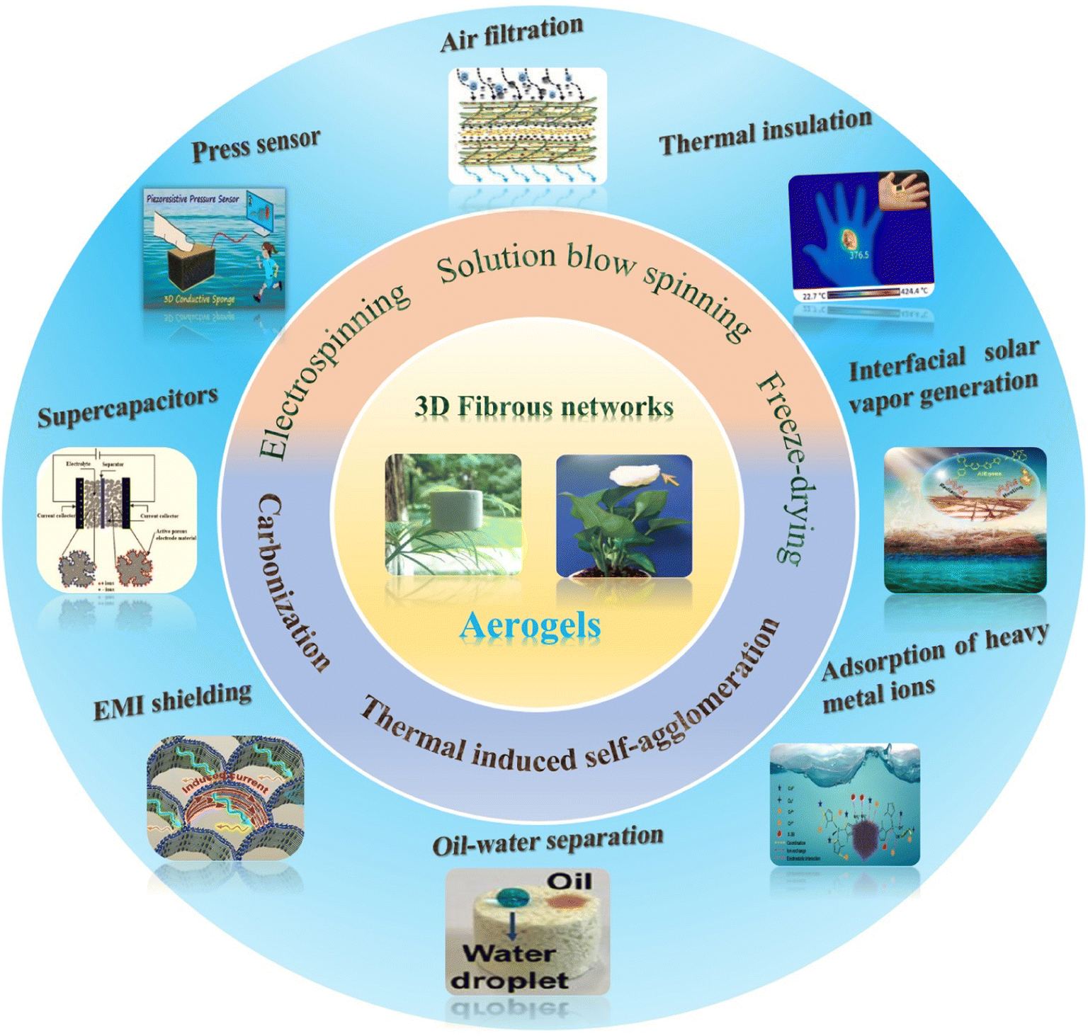 | ||
| Fig. 1 Schematic illustration of the preparation process and potential use of 3D fibrous aerogels in energy and environmental applications. | ||
2. Strategies to synthesize 3D fibrous aerogels
Until now, various methods have been explored to prepare 3D fibrous aerogels. Generally, 3D fibrous aerogels with different structural characteristics can be prepared by using different approaches to assemble nanofibers in the states of single fibers or aggregation. The mechanical and other functional properties of 3D fibrous aerogels are highly dependent on their microstructures. In this section, we mainly introduce the process and characters of recently reported fabrication strategies, involving electrospinning, solution blow spinning, freeze-drying, thermally induced self-agglomeration, and carbonization techniques.2.1 Electrospinning
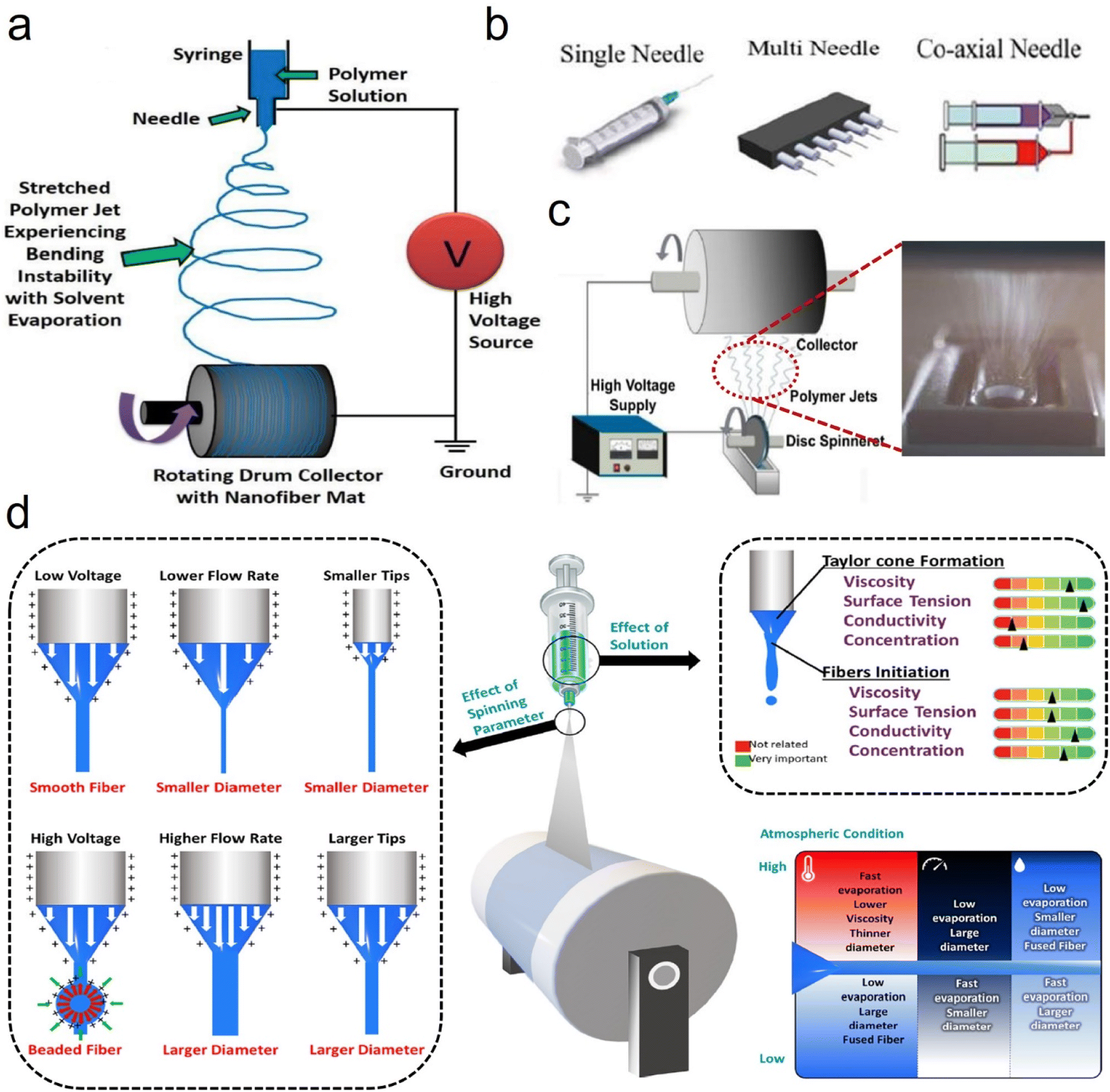 | ||
| Fig. 2 Electrospinning process design and parameters. (a) Schematic representation of the electrospinning process. Reproduced with permission.25 Copyright from 2010, American Chemical Society. (b) Different types of syringes. Reproduced with permission.26 Copyright from 2019, Elsevier. (c) Schematic representation of the needleless electrospinning process. Reproduced with permission.23 Copyright from 2014, Elsevier. (d) Summary of the effects of various processing parameters on the morphology and diameter of electrospun nanofibers. Reproduced with permission.27 Copyright 2022, AIP. | ||
Due to the simplicity of the assembly process and the facile availability of electrospun nanofibers, some researchers have tried to develop and modify electrospinning processes to directly generate 3D fibrous aerogels. The main goal of this design is to construct mechanically robust homogeneous structures capable of forming a 3D cellular architecture, while preserving the inherent functionality of nanofibers. Compared with the 2D compact structure of electrospun mats/membranes, 3D fibrous aerogels with light weight, large porosity, high mechanical strength, and superior sorption properties will be mostly desirable in various fields, such as thermal insulation, adsorption, air filtration, and so on.30,31
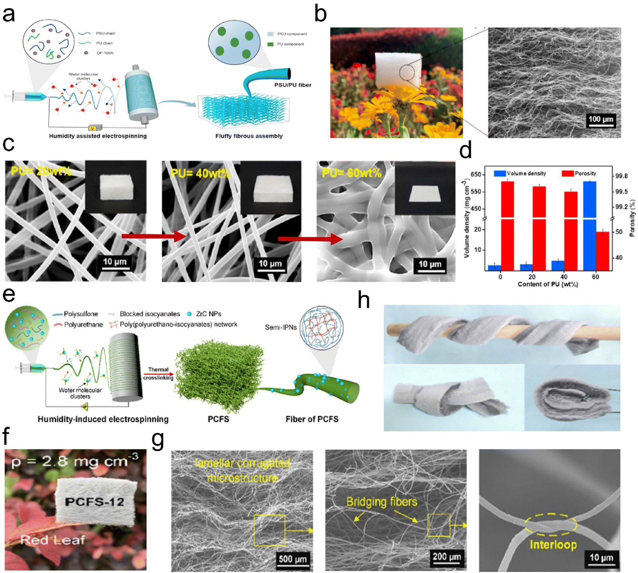 | ||
| Fig. 3 Microstructure of 3D fibrous aerogels prepared by the electrospinning process. (a) Schematic illustration for the fabrication of 3D PSU/PU fibrous aerogels. (b) Photograph and scanning electron microscopy (SEM) image showing the lamellar corrugated microstructure of 3D PSU/PU fibrous aerogels. (c) SEM images, and (d) volume and porosity density of the 3D PSU/PU fibrous aerogels with different contents of PU. Reproduced with permission.30 Copyright 2021, Elsevier. (d) Preparation of the 3D PSU/ZrC fibrous aerogels. (e) Presentation of the synthetic steps for the 3D PSU/ZrC fibrous aerogels. (f) Images showing the softness and toughness of the 3D PSU/ZrC fibrous aerogels. (g) Photographs showing the ultralight properties of the 3D PSU/ZrC fibrous aerogels. (h) Microscopic architecture of the 3D PSU/ZrC-12 fibrous aerogels at various magnifications. Reproduced with permission.31 Copyright 2019, Elsevier. | ||
![[thin space (1/6-em)]](https://www.rsc.org/images/entities/char_2009.gif) 000 times their weight (Fig. 4e). Furthermore, an in situ compression process was observed to reveal the resilience mechanism of 3D fibrous aerogels. The large distance between the lamellar fiber nets gradually decreased and the lamellar fiber nets became densified as the strain increased. After releasing the load, the compact fiber nets could recover to the initial positions without any break (Fig. 4f). The bridging fibers gradually deformed along the loading direction, and after removing the load, the bridging fibers recovered their original shape without breakage (Fig. 4g). These results have demonstrated that introducing elastomer materials or adding some crosslinking agent with heat treatment can effectively improve the mechanical properties of 3D electrospun fibrous aerogels.
000 times their weight (Fig. 4e). Furthermore, an in situ compression process was observed to reveal the resilience mechanism of 3D fibrous aerogels. The large distance between the lamellar fiber nets gradually decreased and the lamellar fiber nets became densified as the strain increased. After releasing the load, the compact fiber nets could recover to the initial positions without any break (Fig. 4f). The bridging fibers gradually deformed along the loading direction, and after removing the load, the bridging fibers recovered their original shape without breakage (Fig. 4g). These results have demonstrated that introducing elastomer materials or adding some crosslinking agent with heat treatment can effectively improve the mechanical properties of 3D electrospun fibrous aerogels.
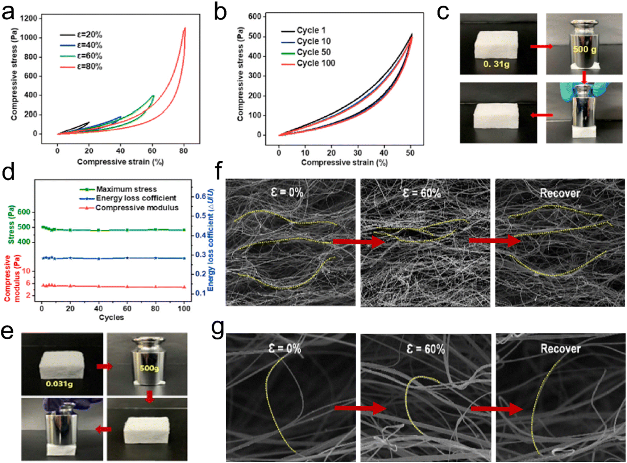 | ||
| Fig. 4 Reversible compressibility of 3D fibrous aerogels prepared by the electrospinning process. (a) Compressive σ–ε curves for the FR PSU/PU-20 fibrous aerogel with various strains of 20%, 40%, 60%, and 80%. (b) A 100-cycle fatigue compression test with ε = 50% of the FR PSU/PU-20 fibrous aerogel. (c) Images showing that the FR PSU/PU-20 fibrous aerogel could quickly recover from large compressive distortion. (d) Maximum stress, compressive modulus, and energy loss coefficient versus compressive cycles. Reproduced with permission.30 Copyright 2021, Elsevier. (e) Images showing that the 3D PSU/ZrC-12 fibrous aerogel could quickly recover from large compressive distortion. In situ observation of the microstructure evolution of (f) lamellar fiber nets and (g) bridging fibers. Reproduced with permission.31 Copyright 2019, Elsevier. | ||
2.2 Solution blow spinning
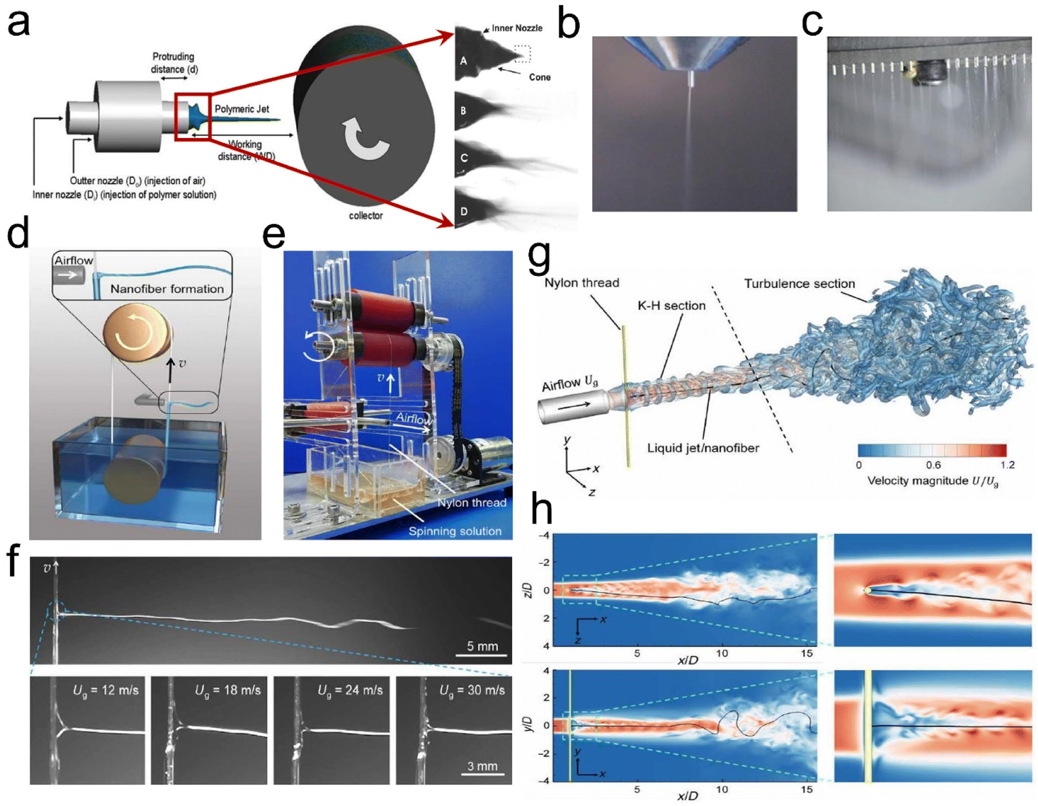 | ||
| Fig. 5 SBS process design strategy. (a) Drum collection schematic. Reproduced with permission.35 Copyright 2020, Royal Society of Chemistry. (b) SBS apparatus with a single-needle spinning die. Reproduced with permission.40 Copyright 2018, Wiley-VCH. (c) SBS apparatus with a multi-needle spinning die. Reproduced with permission.41 Copyright 2017, Royal Society of Chemistry. (d) Illustration of the KV-SBS process. (e) Photograph of a running KV-SBS equipment. (f) The ejected solution captured by using a high-speed camera in the KV-SBS process. (g and h) CFD simulation results of the airflow velocity magnitude coupled with the swing patterns of the fiber in 3D space. Reproduced with permission.42 Copyright 2022, American Association for the Advancement of Science. | ||
Besides, researchers have found some key elements which can affect the fiber formation when using the SBS process, such as solution influence (viscosity, polymer solution concentration, surface tension, and solvent evaporation), process influence (gas pressure, receiving distance, and liquid intake), system influence (nozzle size and collector category), and ambient influence (atmospheric pressure, temperature, humidity, and atmospheric pressure).36–39 Wu et al.40 utilized the SBS process with a single needle (Fig. 5b) to produce various ceramic nanofibers (e.g., TiO2, ZrO2, and BaTiO3). Our groups41 have also developed a multi-needle SBS process (Fig. 5c) to produce some different types of micro/nanofibers, including cellulose, polyacrylonitrile (PAN), polylactic acid, (PLA), and sulfonated polyether ether ketone (SPEEK), which all exhibited excellent fiber morphology and porous structure characteristics. To further prepare fine fibers with a high throughput, Wu et al.42 demonstrated a needleless Kármán vortex (KV)-SBS system to realize high-throughput production of nanofibers. As shown in Fig. 5d–f, the spinning system was assembled by using a roller, a vessel filled with spinning solution, a loop-locked nylon thread, and a gas pipeline set vertically to the thread to provide high-speed air blowing. Driven by the high-speed airflow, the solution was shaped into a Taylor cone and ejected at a high speed, forming nanofibers by fast stretching and swinging. The formation mechanism of nanofibers was studied by fluidic theory analysis, high-fidelity computational fluid dynamics (CFD) simulations, and a bead-spring model for simulating the fiber behavior (Fig. 5g and h). The tailor-made flow configuration combines an airflow and a KV street. The high-speed airflow passing across the nylon thread generated a strong shear stress and KV on the leeward side of the thread, which was beneficial for high-quality nanofiber production.
Based on the relatively proficient SBS process, more research attention has been paid to utilizing the SBS process to prepare 3D fibrous aerogels like ceramic nanofibers. Specifically, within the SBS process, the solidified fibers can be directly collected by using an air-permeable cage-like collector, thereby forming the desired highly porous aerogels. Moreover, the shaped 3D fibrous aerogels by the SBS process show excellent flexibility. Therefore, the SBS process is regarded as a flexible and robust strategy to prepare 3D ceramic fibrous aerogels with a randomly distributed microstructure by changing the initial ceramic precursors.
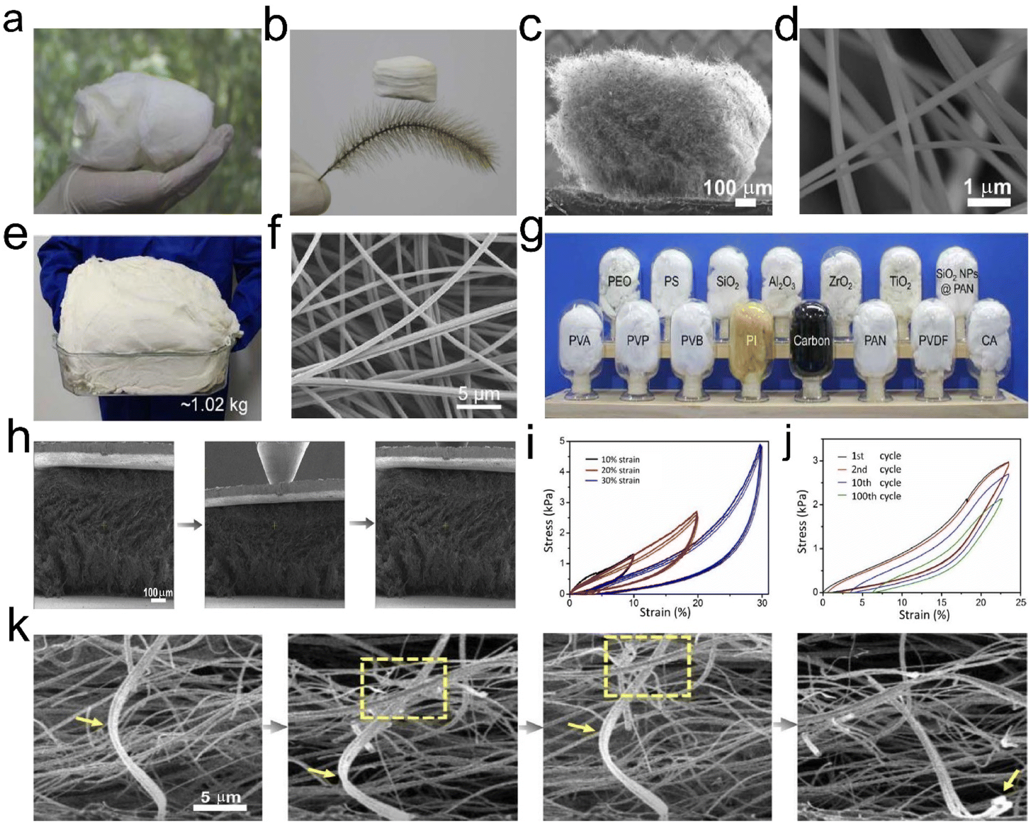 | ||
| Fig. 6 Microstructure of 3D fibrous aerogels prepared by the SBS process. (a) An optical photograph of TiO2 fibrous aerogels. (b) Ultralight TiO2 fibrous aerogel standing on a Setaria viridis. (c and d) SEM image of TiO2 fibrous aerogels with different magnifications. Reproduced with permission.43 Copyright 2019, Elsevier. (d) Photograph of kilogram-scale PS nanofibers fabricated via the KV-SBS process. (e and f) An optical photograph and SEM image of the PS fibrous aerogels. (g) Photographs of various aerogels prepared by the KV-SBS process. Reproduced with permission.42 Copyright 2022, American Association for the Advancement of Science. (h) In situ SEM images of the compressive process of TiO2 fibrous aerogels. (i) Cyclic compressive stress–strain curves of TiO2 fibrous aerogels under 10% to 30% strain. (j) Cyclic compressive stress–strain curves of TiO2 fibrous aerogels under 23% strain for 100 cycles. (k) Zoomed-in SEM images during the compression process. Reproduced with permission.43 Copyright 2019, Elsevier. | ||
2.3 Freeze-drying
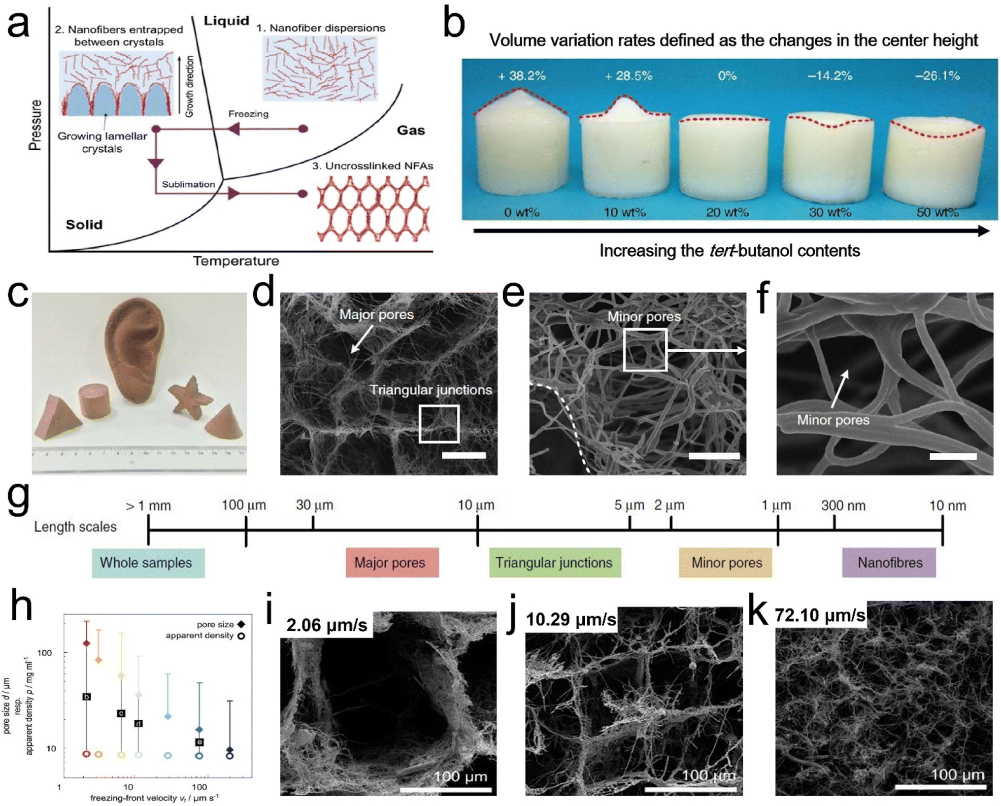 | ||
| Fig. 7 Formation mechanism and microstructure of a hierarchical cellular structure by the freeze-drying process. (a) Mechanism for the formation of the hierarchical cellular structure. (b) Photograph showing the frozen nanofiber dispersions with different concentrations in tert-butanol. The top values indicate the volume variations. (c) An optical photograph of 3D fibrous aerogels with diverse shapes. (d–f) SEM images of 3D fibrous aerogels at various magnifications. (g) Schematic representation of the dimensions of relevant structures. Reproduced with permission.56 Copyright 2022, Springer Nature. (h) Effect of freezing conditions on the aerogel microstructure. (i–k) SEM images showing the cross sections of the respective aerogels at a center height of 7.5 mm obtained with different vf. Reproduced with permission.58 Copyright 2016, Wiley-VCH. | ||
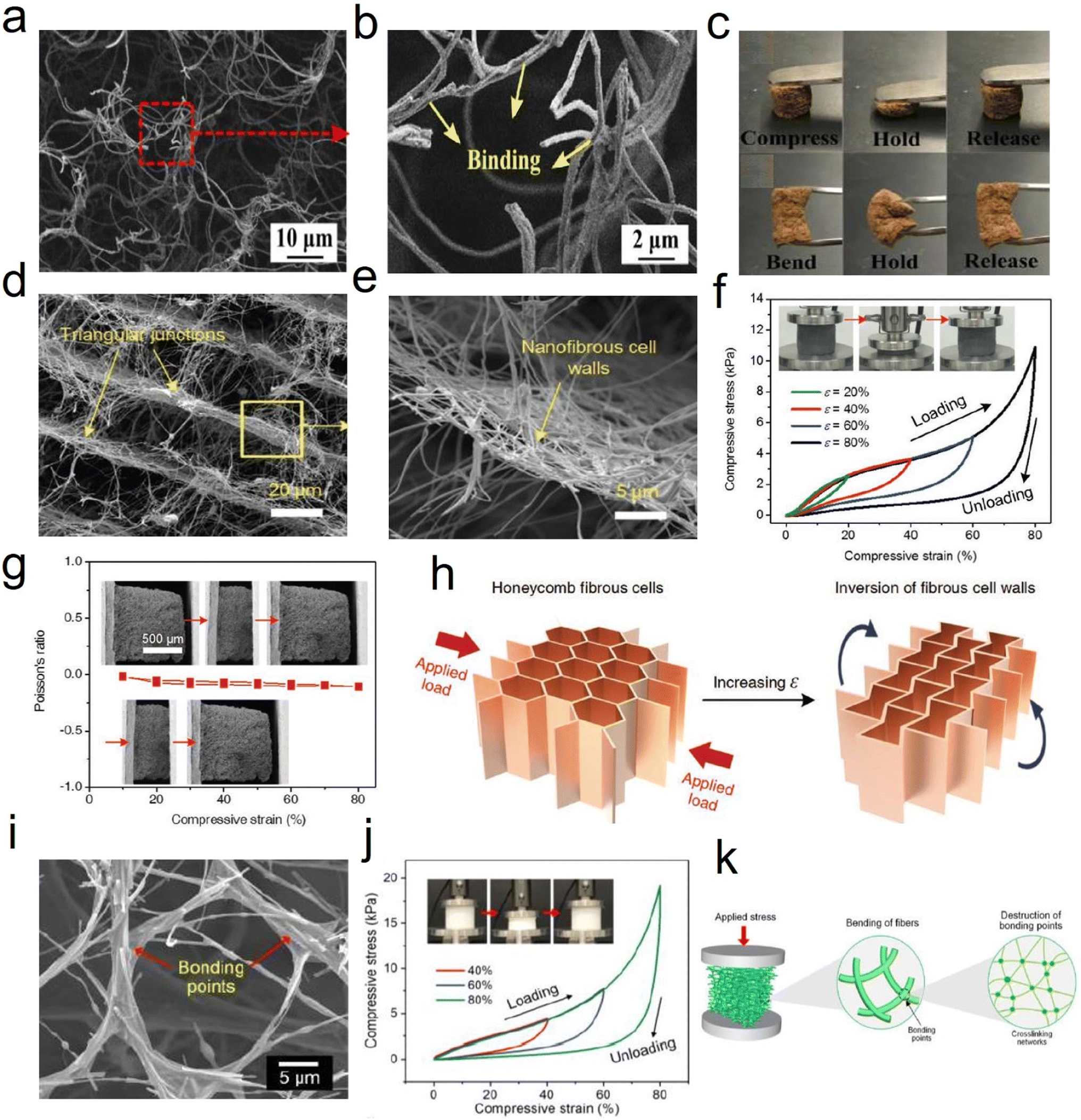 | ||
| Fig. 8 Reversible compressibility of 3D fibrous aerogels prepared by the freeze-drying process. (a and b) SEM images showing the binding of cellulose nanofibers with PVA. (c) A photograph demonstrating the elasticity of a 3D cellulose nanofiber aerogel under compression and bending forces/conditions. Reproduced with permission.57 Copyright 2017, Elsevier. (d–g) SEM images of SiO2/PVA/CCA fibrous aerogels at various magnifications. (h) Compressive stress, and (i) 1000 loading–unloading compression cycle measurement of the SiO2/PVA/CCA fibrous aerogels. Reproduced with permission.59 Copyright 2019, Wiley-VCH. (i) SEM image of the SNF aerogel. (j) Compressive σ–ε curves of aerogels with increasing ε. (k) Schematic showing the compressive process of the aerogels at three levels of the structure: silica nanofiber aerogel, individual nanofiber, and crosslinking network. Reproduced with permission.62 Copyright 2020, Wiley-VCH. | ||
Besides, by regulating the growth direction of ice crystals in the freeze stage, unique honeycomb-like structures can be obtained, which is beneficial to strengthen the mechanical properties of 3D fibrous aerogels. For example, Fu et al.59 developed super-elastic SiO2/polyvinyl alcohol/citric acid (SiO2/PVA/CCA) nanofibrous aerogels with an ordered honeycomb-like structure (Fig. 8d–g). The prepared nanofibrous aerogels showed excellent mechanical properties, and the structure could endure large compressive deformations without cracks, similar to honeycomb-structured materials. Three obvious regions including an elastic linear region (ε < 10%), a plateau region (10% < ε < 60%), and a densification region (ε > 60%) were observed (Fig. 8h). Besides, the SiO2/PVA/CCA nanofibrous aerogels presented nearly no plastic deformation after 1000 compressive cycles at 60% strain (Fig. 8i). Similarly, Qin et al.61 demonstrated a strategy for controlling the growth of ice crystals in both directions that could control the assembly of cellulose nanofibers into sub-micrometer fibers by extremely low-temperature freezing (−196 °C), which could further assemble into an elastic aerogel with interconnected sub-micron fibers by freezer freezing (−20 °C) and freeze-drying. The prepared cellulose fibrous aerogels had isotropic superelastic behavior that could recover from over 80% compressive strain along both longitudinal and cross-sectional directions, even in an extremely cold liquid nitrogen environment. Wang et al.62 developed an in situ synthesis strategy for creating silica nanofiber aerogels with a superelastic biomimetic framework through the combination of flexible SiO2 nanofibers and rubber-like Si–O–Si bonding networks (Fig. 8i). This approach allows the in situ construction of an elastic bonding structure in the biomimetic fibrous framework during the freeze-shaping process. The stress–strain (σ–ε) curves of the prepared aerogels (Fig. 8j) revealed excellent resilience when released from compression. Furthermore, three characteristic regions could be identified in the loading–unloading curves: a nearly linear elastic region for ε < 10%, a relatively flat stress plateau for 10% < ε < 50%, and a subsequent densification region for ε > 50% with a rapid increase in σ. The maximum σ was 19.2 kPa at a strain of 80%, demonstrating that the aerogel could withstand more than 16000 times its weight without collapsing, which was comparable to that of polymeric aerogels with a similar density. Fig. 8k demonstrates how the compressive process could be classified into three levels of hierarchy on different scales: silica nanofiber aerogel, individual nanofiber, and crosslinking network. At the top level, the silica nanofiber aerogel was assembled into a highly ordered biomimetic framework to enhance the elastic modulus and stress. With the increase in compressive strain, the bending of individual nanofibers occurred at the building block level. Finally, the destruction of bonding points consisting of the crosslinking networks is a decisive factor in determining the mechanical properties of the aerogel, which also represents damage at the molecular level. The strength and flexibility of the crosslinking networks would have an immediate effect on the maximum stress and elastic recovery of the silica nanofiber aerogels. Besides, Yang et al.63 reported a combined method of vacuum-assisted filtration (VAF) and freeze-drying processes to prepare 3D MXene/aramid nanofiber (ANF) hybrid aerogels with a hierarchical and “mortar-brick” porous structure. The 3D hierarchical porous network could afford intrinsic power and particular interspacing along with the greatest effect to release the external forces and deformations depending on the merit of a controllable process, which convincingly demonstrated that all hybrid aerogels showed credible compressive resilience and high strength to meet the requirement of a piezoresistance sensor well.64
2.4 Thermally induced self-agglomeration
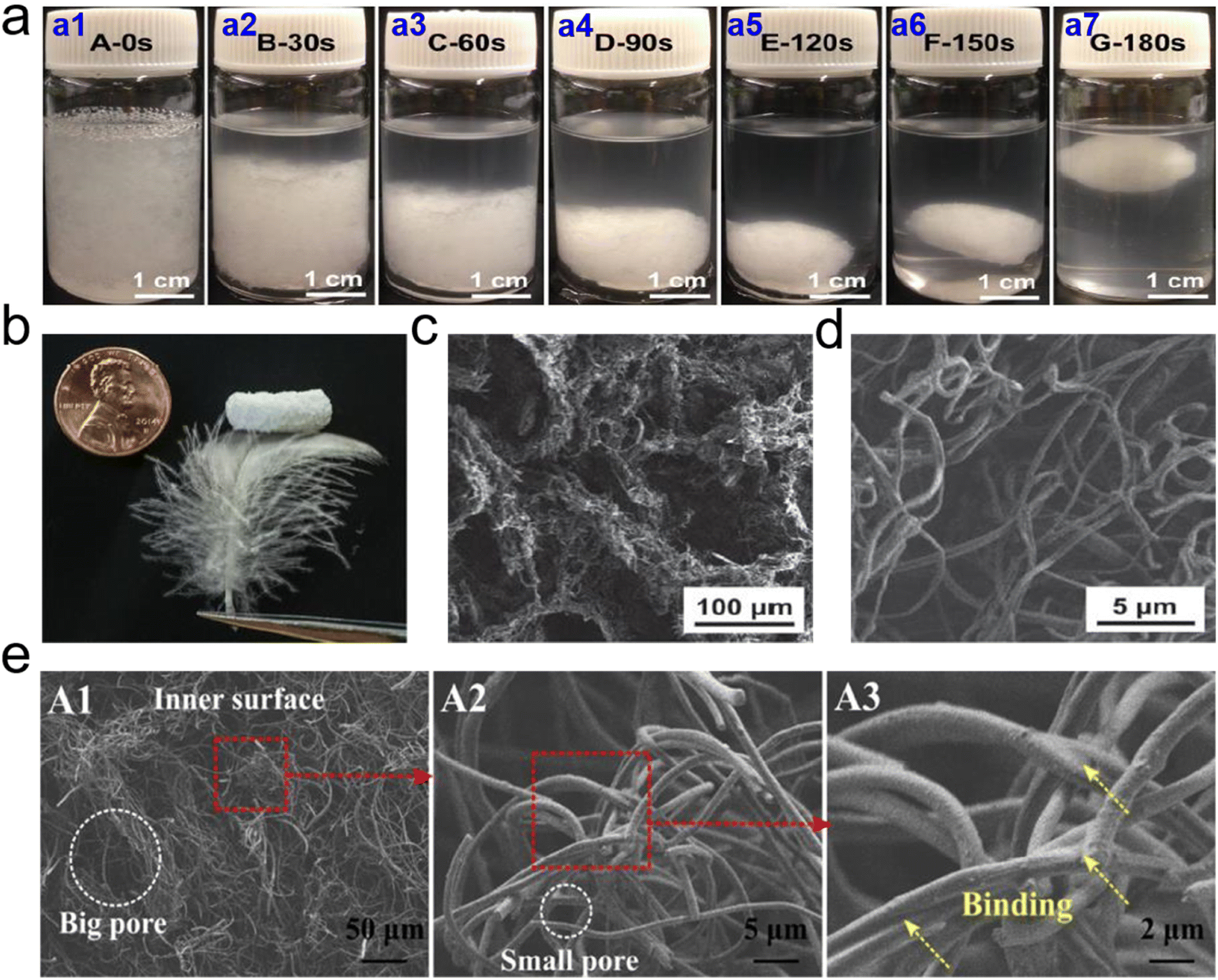 | ||
| Fig. 9 Microstructure of 3D PCL based fibrous aerogels prepared by TISA process. (a) Photographs of 3D PCL fibrous agglomerate prepared by TISA process: (a1) uniform suspension of short nanofibers and tiny pieces of PCL before thermal treatment; and the suspension after being heated at 55 °C for (a2) 30 s, (a3) 60 s, (a4) 90 s, (a5) 120 s (a6) 150 s, and (a7) 180 s, respectively. (b) Macroscopic morphology, and (c and d) SEM images of 3D PCL fibrous aerogels. Reproduced with permission.65 Copyright 2015, Wiley-VCH. (e) SEM images showing typical morphologies of the inner surface of 3D CA/PCL fibrous aerogels. Reproduced with permission.66 Copyright 2018, Elsevier. | ||
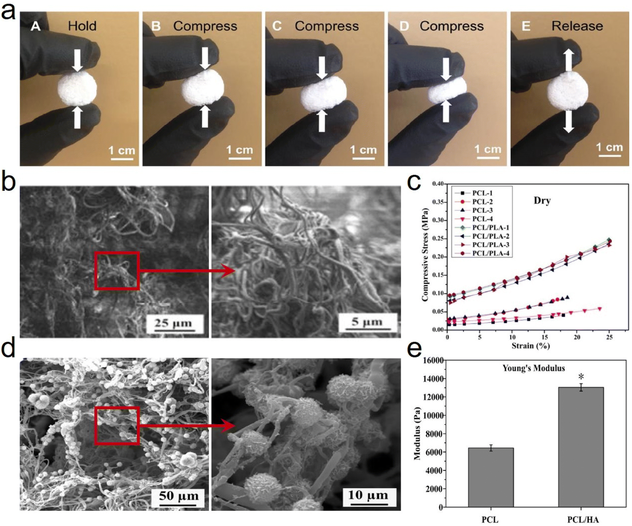 | ||
| Fig. 10 Reversible compressibility and microstructure of 3D PCL based fibrous aerogels prepared by the TISA process. (a) High compressibility and elasticity of 3D PCL fibrous aerogels. Reproduced with permission.65 Copyright 2015, Wiley-VCH. (b) SEM images showing the typical morphologies of a 3D electrospun PCL/PLA fibrous scaffold. (c) Compressive stress–strain curves acquired from PCL-3D and PCL/PLA-3D fibrous aerogels under both dry conditions. Reproduced with permission.67 Copyright 2018, Elsevier. (d) SEM images showing the representative morphologies of PCL/HA coated fibrous aerogels. (e) Young's modulus of PCL/HA-3D fibrous aerogels. Reproduced with permission.68 Copyright 2017, Elsevier. | ||
Besides, cells interact with scaffolds primarily through the surface of scaffold materials, which can be controlled/tailored upon adjusting the surface chemical properties. Furthermore, incorporating functional fillers directly into the scaffold nanofibers as a surface modification is another effective approach to achieve chemical specificity and recognition, which can lead to desired specific intracellular signaling. Fong et al.68 functionalized 3D PCL fibrous aerogels with hydroxyapatite (HA) (Fig. 10d) and bone morphogenic protein (BMP)2 signaling activator phenamil, which provided a favorable osteogenic niche for bone formation at low doses of BMP2. The Young's modulus was measured after PCL fibrous aerogels were modified with HA, yielding an increase from 6438 ± 342 N to 13032 ± 404 N (Fig. 10e). This increased Young's modulus was mainly ascribed to the incorporation of HA which would increase the stiffness/modulus and would not distinguishably vary the ductility/elasticity of the resulting PCL/HA-3D fibrous aerogels. Correspondingly, it's believed that several other surface modification methods on PCL nanofibers, including surface activation, chemical grafting copolymerization, and biomimetic modification, could also be adopted to modify 3D PCL fibrous aerogels and improve many performance characteristics including mechanical properties.
2.5 Carbonization
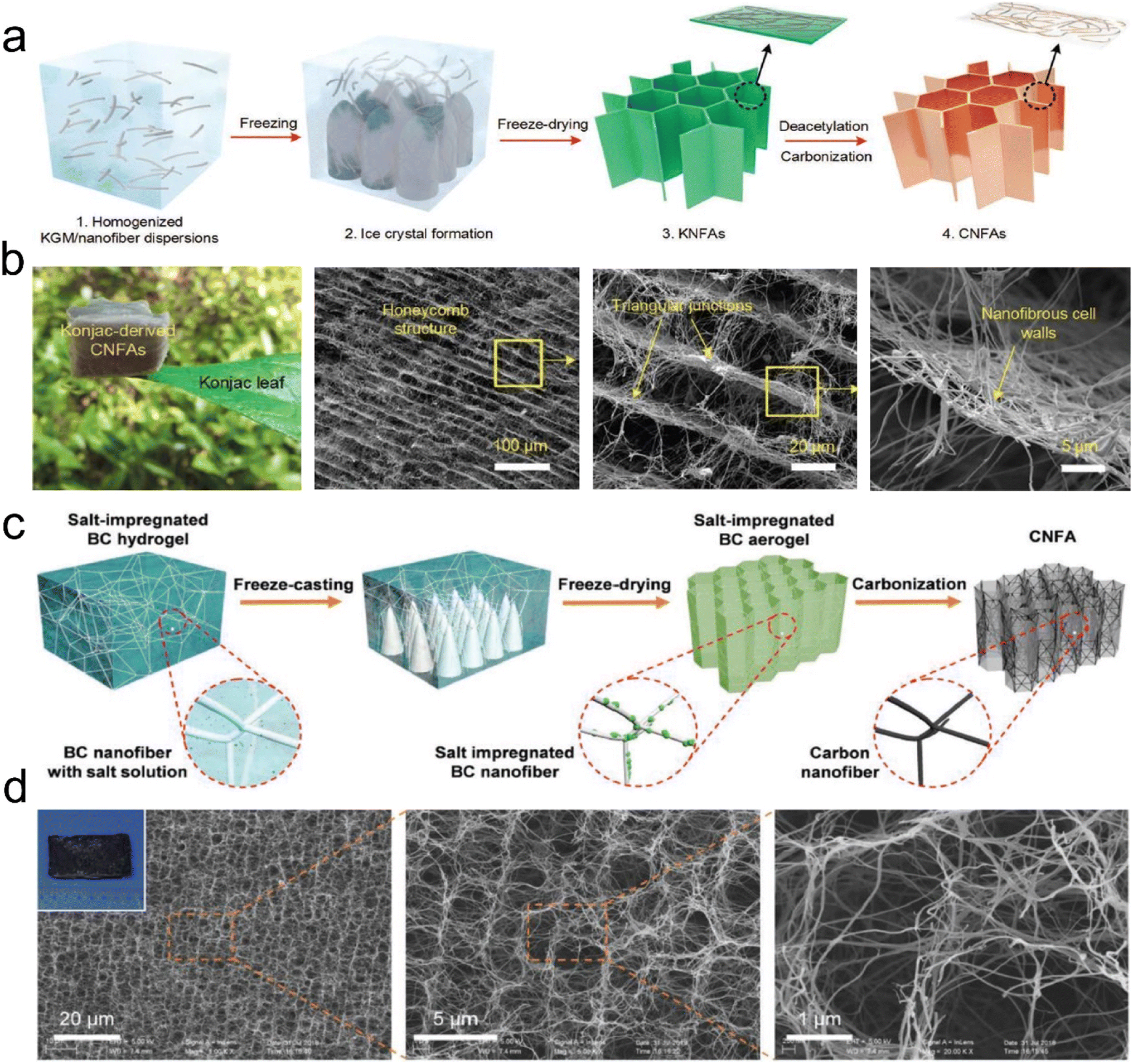 | ||
| Fig. 11 Preparation process and microstructure of CNFAs. (a) Schematic showing the synthetic steps for preparing CNFAs. (b) SEM images of CNFAs at various magnifications. Reproduced with permission.60 Copyright 2017, Wiley-VCH. (c) Schematic illustration of the fabrication processes of CNFAs. (d) SEM images of CNFAs, demonstrating that the CNFAs fully inherited the hierarchical structure from BC. Reproduced with permission.77 Copyright 2019, Wiley-VCH. | ||
000 cycles, with a high-stress retention of 86.1% at 30% and 85.3% at 50%, which further verified the superior compressibility and elasticity of CNFAs (Fig. 12f). The compressible and elastic mechanism of the CNFAs is proposed in Fig. 12g to illustrate their excellent structural stability. In the structural model, the regular honeycomb structure of CNFAs made it possible to avoid slipping and splitting along the perpendicular direction of compression, which was more conducive to the storage of elastic energy. Besides, Zhang et al.76 prepared PAN/PVP derived hybrid CNFAs, in which PVP could act as an adhesive or “solder” to “weld” adjacent nanofibers. Correspondingly, the CNFAs could withstand a compressive strain (ε) of up to 80% and recover to their original height upon releasing the compression stress (σ). Cyclic compression tests of the CNFAs were performed by applying 100 loading–unloading compression cycles at a constant strain of 50%. Therefore, CNFAs featuring excellent structural stability are considered promising candidates do use in electronic fields.
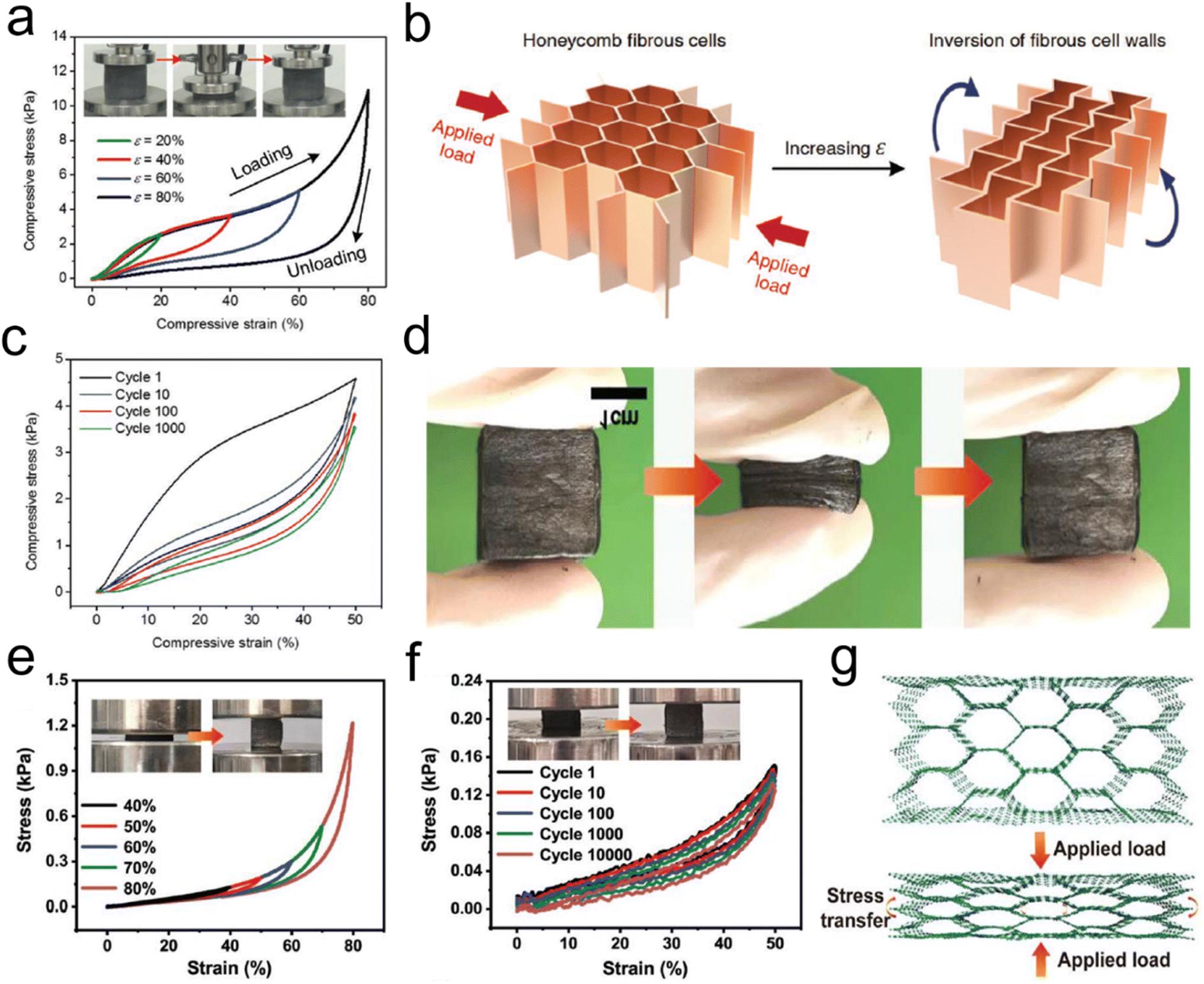 | ||
| Fig. 12 Reversible compressibility of CNFAs. (a) Compressive σ versus ε curves for CNFAs along the loading direction. (b) Schematic demonstration of the inversion of the fibrous cell walls with compressive ε. (c) 1000 cyclic fatigue compressive test with an ε of 50%. Reproduced with permission.60 Copyright 2017, Wiley-VCH. (d) Compression and recovery process of typical CNFAs. (e) Stress–strain curves of CNFAs at different compression strains. (f) Stress–strain curves at 80% strain for 100 cycles, and (g) schematic illustration showing the compressive deformation for the CNFAs. Reproduced with permission.80 Copyright 2022, Wiley-VCH. | ||
In general, the recently reported fabrication strategies, involving electrospinning, solution blow spinning, freeze-drying, thermally induced self-agglomeration, and carbonization techniques have been widely adopted to prepare various 3D fibrous aerogels. Table 1 summarizes the advantages and disadvantages of the synthesis methods and the corresponding physical parameters, which provides great guidance to fully understand the differences among the preparation methods.
| Preparation method | Microstructure | Process parameters | Typical characteristics | Advantages | Disadvantages | Ref. |
|---|---|---|---|---|---|---|
| Electrospinning | Randomly | Spinning solution, high voltage power, collector | Lightweight, high specific surface area, large porosity, flexible, good tensile properties | Abundant raw materials, diverse fiber morphology (e.g., core–shell and porous) | Electrostatic field interference, time-consuming, difficult solvent recovery | 27 |
| Solution blow spinning | Randomly | Spinning solution, high-velocity gas flow, collector | Lightweight, high specific area, large porosity, flexible, elastic, mechanical stability | Abundant raw materials, high-production, safety | Difficult solvent recovery | 35 |
| Freeze-drying | Randomly, anisotropic | Fiber dispersion, dispersion medium, binding agent | Lightweight, high specific surface area, large porosity, flexible, elastic, good mechanical stability | Abundant raw materials, simple process, high-production | Low-temperature, time-consuming | 56 |
| Thermally induced self-agglomeration | Randomly | Short polycaprolactone nanofibers | Lightweight, high specific surface area, large porosity, stiff, good mechanical stability | Sample process, without binding agents | Less raw materials, toxic solvent | 65 |
| Carbonization | Randomly, anisotropic | Shaped aerogels, high-temperature | Lightweight, high specific surface area, large porosity, elastic, flexible, good mechanical stability, electro-conductive | Abundant raw materials, novel function (e.g., electrical conduction) | High-temperature (600–1400 °C), complex process | 77 |
3. Applications of 3D fibrous aerogels
3.1 Air pollutant filtration
Air pollution caused by fine particulate matter (PM) and toxic gases has become an increasing public health hazard globally. PM, as a complex mixture, is typically categorized as PM0.3, PM2.5, and PM10, which refer to particle sizes below 0.3, 2.5, and 10 μm, respectively. Among them, PM0.3 is especially harmful because it can travel long distances, penetrate small airways, and carry various bacteria/viruses. To achieve efficient removal of PMs and toxic gases, the design of air filters with high selectivity and low cost has attracted considerable attention.84,85 Generally, the fiber diameter for air filters needs to be considered for achieving the efficient capture of PMs. For PM0.3 and PM2.5, the diameter range of fibers is usually 20–200 nm and 50–2000 nm, respectively, so that the filter material can achieve a filtration efficiency greater than 99.99%.86,87 To date, the existing fibrous filter media (e.g., melt-blown polypropylene, PI, etc.) often suffer from an extremely low filtration efficiency toward poisonous PM2.5 and PM0.3 due to their microsized fiber diameters. Alternatively, electrospun fibrous membranes are deemed effective in capturing PMs based on their small fiber diameters, tunable porous structure, and ease of preparation from various materials. However, the electrospun air filtration materials exhibit a high-pressure drop due to the dense packing of nanofibers (with a limited porosity of <90%), finally giving rise to large energy consumption. At the forefront of advanced materials, a 3D fibrous aerogel featuring a large specific surface area, high porosity, and abundant interconnected channels, is developing into a more favorable candidate for air filters than 2D membranes.The current relevant reports mainly focus on using electrospun nanofiber membranes to construct 3D fibrous aerogels for improving air filtration efficiency and selectivity. For example, Hu et al.88 prepared silk nanofibril (SNF) aerogels with controlled structures and excellent mechanical resilience. The nanofibril network and hierarchical cellular structure of the prepared aerogels (Fig. 13a) were tuned by the assembly of SNFs and foreign PVA. The SNF aerogels exhibited a high filtration efficiency of 98% and quality factor towards PM0.3 (Fig. 13b and c), which were far superior to those of PP nonwovens and commercial masks when the PM had sizes of 0.3–3 and 5–10 μm. Qian et al.89 developed electrospun PI nanofibers as building blocks to construct PI fibrous aerogels with a hierarchically porous architecture, which achieved a capture efficiency of 99.9% for PM2.5 and a low-pressure drop of 177 Pa. However, once massive particles are deposited or subjected to high airflow velocity, less solidity may cause the collapse of the cellular structure, as evidenced by the low compressive stress (≈1.4 kPa at a strain of 60%) and modulus (6.1 kPa) of PI fibrous aerogels. Moreover, electrospun fibrous aerogels derived from PI and other materials (e.g., PVA) all suffer from a monoassembling structure parallel to the filtering direction, which would cause the inability to collect polydisperse fine particles as a uniform deposition pattern, resulting in a short service life.90 To address these issues, Si et al.91 proposed a biomimetic and bottom-up strategy to prepare superelastic and thermostable fibrous aerogels as cascade filters through assembling semi-interpenetrating polymer network (semi-IPN)-based nanofibers into a gradient architecture. The mechanical properties of fibrous aerogels were improved by tailoring the chain flexibility of heat-resistant semi-IPNs. The resultant semi-IPN-based gradient fibrous aerogels exhibited a high compressive stress of 7.9 kPa and high filtration efficiency of 99.97% towards PM0.3. Similarly, Wang et al.92 reported the preparation of cage-like structured aerogels (CSAs) by combining electrospun silica nanofibers, BC nanofibers, and the hydrophobic Si–O–Si elastic binder, which aimed at achieving excellent air filtration performance and the effective inactivation of airborne pathogens simultaneously. Fig. 13d demonstrates the antibacterial and antiviral air filtration process of the aerogels. When contaminated air came into contact with CSAs-Cl, the fine BC nanonets would intercept viruses and bacteria; meanwhile, the aerogels could release oxidative chlorine and kill pathogens by directly reacting with the vital bacterial cell constituents (such as enzymes and proteins). The resultant fibrous aerogels showed high filtration performance toward PM0.3 (>99.97%, 189 Pa), and excellent antibacterial and antiviral activity (6 log reduction within 5 min contact) (Fig. 13e–h). These results all indicated that 3D fibrous aerogels could serve as a scalable biocidal air filter that not only intercepts but also effectively kills pathogens in infected air, revealing their practicability in antimicrobial air filtration. Zhang et al.93 reported a novel hydroxyapatite (HAP) nanowire-based inorganic aerogel with excellent elasticity, which was highly porous (porosity ≈ 99.7%) and ultralight (density 8.54 mg cm−3, which is about 0.854% of water density). The as-prepared hydrophobic HAP nanowire aerogel filter had high PM filtration efficiency, low-pressure drop, good mechanical properties, and high biocompatibility; thus, it was promising for applications in breathing masks and air purifiers. Therefore, these advanced research studies have demonstrated that the development of 3D fibrous aerogels brings about an improved performance in the capture of air pollutants, which is ascribed to a combination of properties, such as large and highly open porosity, high specific surface area, polar–polar interaction with PMs, abundant cavities and efficient gas adsorption sites.
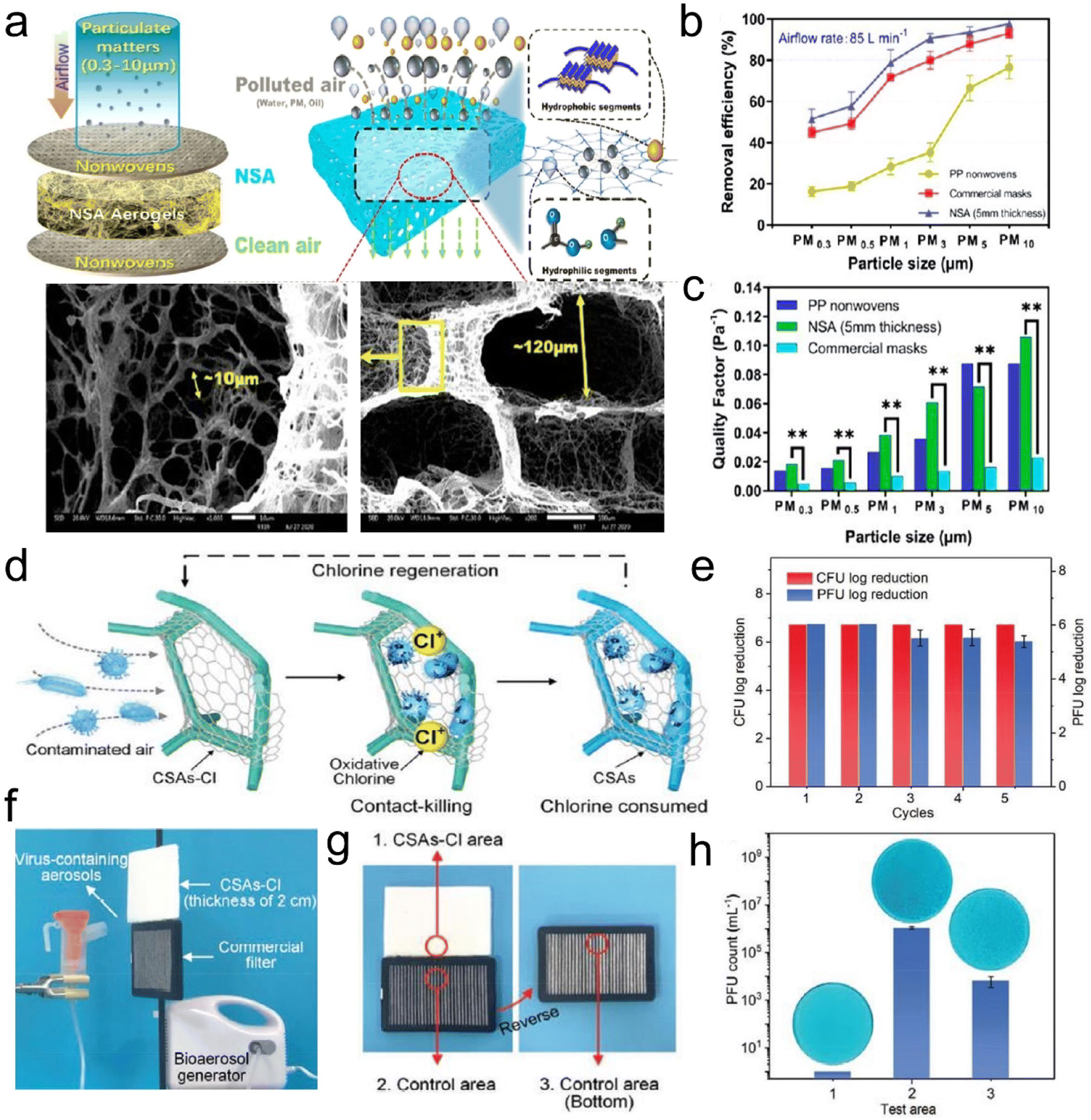 | ||
| Fig. 13 3D fibrous aerogels used in air filtration. (a) Illustration of the contaminants captured by SNF aerogels. (b) Removal efficiency at 85 L min−1 for differently sized particles. (c) Quality factor of the three kinds of materials at 85 L min−1 for differently sized particles. Reproduced with permission.88 Copyright 2021, American Chemical Society. (d) Illustration showing the air filtration procedure of the aerogels. (e) Renewable antibacterial and antiviral properties of CSAs-Cl. (f) Virus-containing aerosol generator and the antiviral test using an aerogel and 3 M filter. (g and h) The antiviral properties of the selected three areas of the filters. Reproduced with permission.92 Copyright 2021, Wiley-VCH. | ||
3.2 Thermal insulation
Decreasing heat transfer through advanced thermal insulators is an effective way to improve energy efficiency and reduce the world's total energy consumption.94 Thermal insulation is also urgently needed for many personal thermal protection systems in harsh environments. Thermal insulators are generally defined as materials that retard the heat flow through conduction, convection, and radiation.95–97 Trapped air pockets in the cellular fibrous structure of aerogels provide a region of insulation that not only effectively reduces the heat transfer via convection but also obstructs heat conduction pathways.98 During heat convection, a bulk stream of gas driven by buoyancy and temperature differences moves around, but in 3D fibrous aerogels, with a large number of air-filled pockets, there is a small density difference to drive heat convection. The high surface area of the tortuous pores filled with low-density air blocks the heat conduction path and resists gas flow by minimizing its movement. Besides, the physically entangled and/or chemically crosslinked networks for 3D fibrous aerogels can considerably avoid stress concentration and show mechanical and flexible behavior. Thus, 3D fibrous aerogels are developing into a more favorable candidate as thermal insulators.Organic polymer nanofiber-assembled 3D fibrous aerogels have shown promising thermal insulation properties. For example, Tuo et al.99 reported a bottom-up strategy for the preparation of 3D ANF aerogels by a vacuum-assisted self-assembly technique. The obtained ANF aerogel was pressed to 25% of the original height (ε = 75%), which could recover to 59.6% and 52.4% of the original height in the axial direction and the radial direction, respectively. The thermal conductivity (Fig. 14a) of the ANF aerogel in the radial and axial directions (25 °C) was 0.0418 ± 0.0006 and 0.0372 ± 0.0004 W m−1 K−1, respectively. Jiang et al.100 prepared hierarchically 3D fibrous aerogels using PI as a high-temperature stable polymer and PAA as a binder. The 3D fibrous aerogels with a density of 10.1 mg cm−3 showed a low thermal conductivity of 0.026 W m−1 K−1 and thermal diffusivity of 1.009 mm2 s−1. As shown in Fig. 14b, a hot iron plate (∼376 °C) could be held on hand with the assistance of the PI aerogel, and the gradient distribution of temperature from the plate to the 3D fibrous aerogels was observed when the PI aerogel was put on a heating plate (∼400 °C). Zhou et al.101 prepared hybrid aerogels (cellulose nanofiber@Al-MIL-53, CAM) by a stepwise assembly approach involving the coating and cross-linking of cellulose nanofibers with continuous nanolayers of MOFs. The CAM aerogels had a cellular network structure and hierarchical porosity, which endowed the aerogels with a relatively low thermal conductivity of ∼40 mW m−1 K−1. As shown in Fig. 14c, a 1 cm-thick section of the CAM aerogel was placed on a 300 °C heating stage. The temperature at the top surface of the Al-MIL-53 pellet and the pure cellulose nanofiber aerogel reached 207.1 and 213.6 °C, respectively. Remarkably, the temperature on the top surface of the CAM aerogel only slightly increased to 58.2 °C. However, some fibrous aerogels assembled from organic polymer nanofibers could not withstand high-temperature conditions (>900 °C), showing structural collapse and volume shrinkage to some extent. Therefore, 3D fibrous aerogels with sufficient mechanical robustness (both high strength and superelastic) and excellent high-temperature resistance are the critical roadblocks to their reliable application under industrial, aerospace, and even extreme environmental conditions.102–104
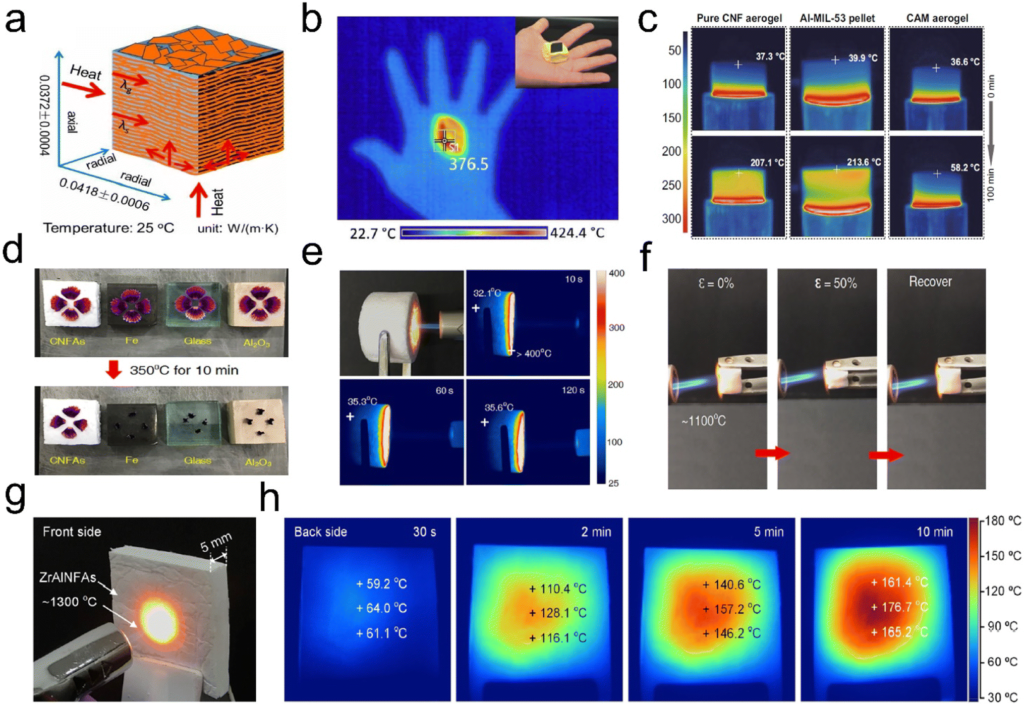 | ||
| Fig. 14 Thermal insulation performance of 3D fibrous aerogels. (a) Thermal conductivity of the ANF aerogel in different directions. Reproduced with permission.99 Copyright 2019, American Chemical Society. (b) Infrared camera image showing the thermal insulation of the PI aerogel: a hot iron plate (∼376 °C) was held on hand with the assistance of the PI aerogel. Reproduced with permission.100 Copyright 2017, American Chemical Society. (c) Infrared side-view images of the pure cellulose nanofiber aerogel, the pure Al-MIL-53 pellet, and the CAM aerogel, with the temperature of the top surfaces. Reproduced with permission.101 Copyright 2020, Springer Nature. (d) Thermal insulation capacity of the ceramic fibrous aerogels compared with those of Fe, SiO2, and Al2O3 materials for protecting fresh petals from withering. (e) Optical and infrared images of ceramic fibrous aerogels on a 350 °C heating stage for 30 min. (f) Optical and infrared images of ceramic fibrous aerogels exposed to a butane blowtorch for 120 s. Reproduced with permission.56 Copyright 2020, Springer Nature. (g) Optical photograph of the front side subjected to a butane blowtorch flame. (h) Infrared images of the back side during a 10 min heating process. Reproduced with permission.111 Copyright 2020, American Chemical Society. | ||
Recently, the emerging ceramic fibrous aerogels have become the most attractive candidates for thermal insulation because of their low thermal conductivity and excellent fire and corrosion resistance, which can bear extreme temperatures.104–109 For example, Liu et al.56 reported a scalable strategy to develop superelastic ceramic fibrous aerogels by combining SiO2 nanofibers and aluminoborosilicate (AlBSi) matrices. The thermal conductivity of the aerogel was 0.025 W m−1 K−1, which was closed to that of air under ambient conditions (0.023 W m−1 K−1). As shown in Fig. 14d, fresh flower petals placed on the top of the ceramic fibrous aerogels only slightly shrivel up after being on a hot stage (350 °C) for 10 min, whereas other ceramic materials such as iron, glass, and Al2O3 scorch and carbonize these petals. The ceramic fibrous aerogels (15 mm thick) had superior thermal insulation against a high-temperature butane blowtorch flame, showing a relatively low temperature of 35 °C at the far end of the aerogels (Fig. 14e). The high-temperature elasticity and fire resistance of the ceramic fibrous aerogels were further assessed by in situ compression testing in the flame of a butane blowtorch (∼1100 °C). As depicted in Fig. 14f, no ignition or structural collapse was observed when the aerogels were exposed to those high-temperature flames; moreover, they still exhibited good elastic resilience after several compression cycles upon flame burning, highlighting the temperature-invariant superelasticity. Similarly, Dou et al.110 synthesized a hierarchical cellular structured silica fibrous aerogel using SiO2 nanofibers and SiO2 nanoparticle aerogels (SNAs) as the matrix and SiO2 sol as the high-temperature nanoglue. The as-prepared ceramic fibrous aerogels showed ultralow thermal conductivity (23.27 mW m−1 K−1) and temperature-invariant superelasticity from −196 to 1100 °C, making them ideal for thermal insulation applications. Besides, Si et al.111 reported the facile creation of lamellar multiarch structured ZrO2–Al2O3 fibrous aerogels (ZrAlNFAs) with temperature-invariant mechanical robustness through combining flexible ZrO2–Al2O3 nanofibers with Al(H2PO4)3 (AHP) matrices. Fig. 14g presents the optical photograph of the front side of ZrAlNFAs (thickness of 5 mm), which have been subjected to flames of about 1300 °C from a butane blowtorch. The back-side surface of the ZrAlNFAs showed a gentle increase in temperature from 60 °C for 30 s, 160 °C for 5 min, and finally an almost constant 180 °C with further heating after 10 min (Fig. 14h). The lamellar structure, high porosity (>98%), and all-ceramic components endowed the ZrAlNFAs with temperature-invariant compressibility, high fire resistance up to 1300 °C, a thermal conductivity as low as 0.0322 W m−1 K−1, and high-temperature thermal insulation performance. Therefore, these research studies demonstrate that ceramic fibrous aerogels can be recognized as a promising alternative to the existing thermal insulation materials under extreme environments.
3.3 Pressure sensors
With the foreseeable prosperity of artificial intelligence, high-performance pressure sensors with light weight, mechanical compliance, high sensitivity, fast response, a wide response range, and stability have emerged, promising a myriad of applications such as artificial prosthetics, smart robots, electronic skin, and wearable electronics.112–115 Aerogels with electricity properties are considered a promising material for pressure sensors combining high conductivity and mechanical properties. So far, CNTs or graphene aerogels/sponges have been widely reported as pressure sensors. However, they typically possess either large (tens of micrometers) or small (several micrometers or smaller) pores but not both, whereas the hierarchical structures that possess wide pore size distributions from small to large pores are desired for wide strain range strain/pressure sensors. Recently, fibrous aerogels with a 3D architecture are regarded as the most ideal candidate for pressure sensors because of their low density, high porosity, and excellent elasticity. Typically, Si et al.60 prepared superelastic CNFAs with an ordered honeycomb-like structure by combining KGM and flexible SiO2 nanofibers. This excellent mechanical stability could make the aerogels sense dynamic pressure with a wide pressure range and high sensitivity, which enabled real pressure signals (e.g., human blood pulses) to be monitored in real time and in situ (Fig. 15a and b). Hou et al.116 reported PI-derived CNFAs with high fatigue resistance and excellent flexibility, and the aerogels showed elasticity-dependent electrical resistance as piezoresistive stress sensors. However, the conductivities of these 3D CNFAs were deeply affected by the carbonization process and might not be accurately regulated. For the compressive strain sensor, high conductivity could lead to small change of conductivity and thus low sensitivity in sensing applications. Fong et al.117 demonstrated a promising strategy for preparing highly porous 3D fibrous aerogels with tunable conductivity for making tactile pressure sensors. Within this design, the PAN and PI nanofibers showed mechanical resilience, and electrospun carbon nanofibers provided tunable electrical conductivity. The resistance of the 3D fibrous aerogels could vary from ∼260 kΩ to ∼200 Ω with the addition of carbon nanofibers. Under compressive strain, the resulting sensors based on these aerogels had high sensitivity over a wide range of compressive strain and stability (Fig. 15c). The tactile pressure sensor array (Fig. 15d) of 3D fibrous aerogels represented the advanced applications of these materials, indicating a promising candidate for the design of highly sensitive tactile sensing devices. This provides a new approach for designing 3D porous fibrous aerogels or aerogels with multiple functions by incorporating functional materials and fragmented nanofibers as building blocks.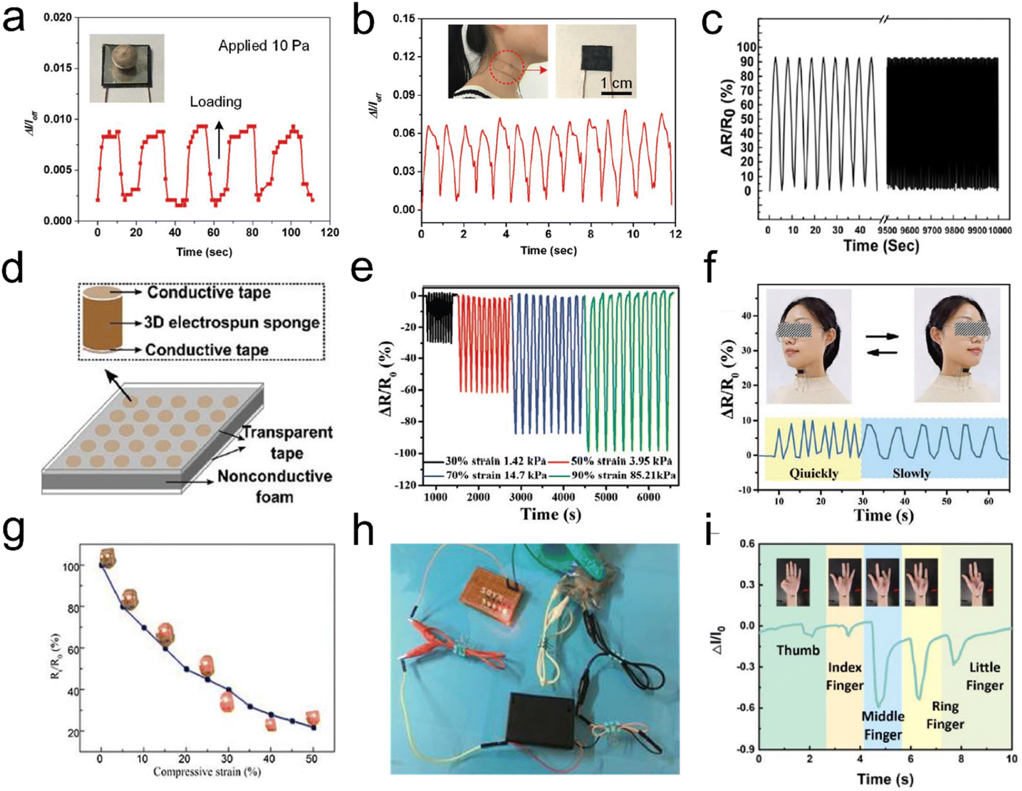 | ||
| Fig. 15 3D fibrous aerogels used in pressure sensors. (a) Response and relaxation of the pressure sensor upon loading and unloading of a pea with a pressure of 10 Pa. (b) Measurement of the human neck pulse under normal conditions, indicating 72 beats per min. Reproduced with permission.59 Copyright 2016, Wiley-VCH. (c) The resistance change of the 3D conductive aerogels. (d) Schematic of a proof-of-concept matrix of the sensor array. Reproduced with permission.117 Copyright 2017, Royal Society of Chemistry. (e) Cyclic piezoresistive sensing performances of the PINF/MXene aerogel under different compression strain/pressure levels. (f) Sensing performances of the PINF/MXene aerogel served as a pressure sensor for the real-time detection of head shaking. Reproduced with permission.118 Copyright 2021, Wiley-VCH. (g) The Rt/R0 – compressive strain curve of the 3D fibrous aerogels. (h) Photographs of a circuit based on compressed 3D fibrous aerogels at different strains with a light lamp. Reproduced with permission.120 Copyright 2017, Elsevier. (i) Bending signal of different fingers. Reproduced with permission.121 Copyright 2022, Elsevier. | ||
For the purpose of preparing high-sensitivity flexible pressure sensors, active materials are generally considered. Different choices of active materials have an immediate and profound influence on their sensing performance. The traditional pressure sensors based on metals or semiconductors face the problems of poor flexibility and a narrow pressure range, which greatly limit their application in wearable devices. Currently, some conductive nanofillers (e.g., MXene, graphene, CNTs, polypyrrole (Ppy), silver, copper, etc.) have been regarded as active materials, which strongly promote the development of flexible pressure sensors. Liu et al.118 developed a conductive polyimide nanofiber (PINF)/MXene hybrid aerogel with a “layer-strut” bracing hierarchical fibrous cellular structure. Benefiting from the porous architecture and robust bonding between PINF and Mxene, the PINF/MXene hybrid aerogel exhibited an ultralow density (9.98 mg cm−3), intriguing temperature tolerance from 50 to 250 °C, superior compressibility and recoverability (up to 90% strain), and excellent fatigue resistance over 1000 cycles. The hybrid aerogel could be used as a pressure sensor, with an outstanding sensing capacity up to 90% strain (corresponding 85.21 kPa), ultralow detection limit of 0.5% strain (corresponding 0.01 kPa), robust fatigue resistance over 1000 cycles, excellent pressure stability, and reproductivity in extremely harsh environments (Fig. 15e and f). Similarly, Yang et al.119 reported an MXene/ANF fibrous aerogel with high compressible resilience and appealing sensing performance up to 1000 cycles. The MXene/ANF fibrous aerogel based sensor demonstrated a wide detection range (2.0–80.0% compression strain), sensitive sensing properties (128 kPa−1), and ultralow detection limit (100 Pa), which still played a flexible role in detecting human light movement and even vigorous sports after undergoing ultrahigh devastating pressures (∼623 kPa). Besides, Yao et al.120 reported the preparation of self-reporting Ag nanoparticles (AgNPs)/cellulose nanofiber aerogels as stress sensors. To test the electrical conductivity of 3D fibrous aerogels and exam the relationship between normalized electrical resistance (Rt/R0) and compressive strain, the aerogels were connected with a lamp in a simple circuit (Fig. 15g). The Rt/R0 dramatically decreased by 65% with an increase of strain to 20%. This result was ascribed to the fact that the compression could create numerous new temporary contacts among cellulose nanofibers and AgNPs paths in the whole aerogel, thereby reducing the electrical resistance. It was illumined with a light-emitting diode in a 3 V circuit, and its brightness fluctuated as the aerogel was compressed (Fig. 15h). Qin et al.121 prepared a brand-new and high-performance flexible pressure sensor based on Ppy/CA fibrous hybrid aerogels. The prepared flexible pressure sensor could exhibit an ultra-high sensitivity (60.28 kPa−1) and wide pressure range (0–24 kPa), which was suitable for realizing the real-time monitoring and identification of human motions (Fig. 15i). It can provide a broad application prospect in the field of wearable electronic devices due to its simple preparation process and excellent piezoresistive performance.
3.4 Triboelectric nanogenerators
Energy harvesting technologies of electromechanical transformation, such as triboelectric nanogenerators (TENGs), piezoelectric nanogenerators (PENGs), and electromagnetic generators (EMGs), have gained more attention due to the rapidly increasing demand for clean and sustainable energy resources for new electronic devices (e.g., smart wearable self-powered sensors, mobile communication electronics, etc.).122–126 Among these emerging technologies, TENGs have proven to be viable candidates for lightweight energy harvesting devices, wearable sensors, and health monitoring devices due to their low cost, light weight, flexible structures, and ease of fabrication, since first reported in 2012.124 As is well known, several working modes for TENGs have been widely developed based on the same fundamental principle: vertical contact-separation mode, lateral-sliding mode, single-electrode mode, and freestanding triboelectric-layer mode.125 Besides, with the aid of state-of-the-art material characterization techniques, the charge transfer mechanisms for TENGs could be categorized into three possible models, which are responsible for triboelectricity: electron transfer model, ion transfer model, and material transfer model. For 3D fibrous aerogel-based TENGs, the working mechanism and ion transfer model of the charge transfer mechanism are shown in Fig. 16. The physical fundamentals of TENGs are the triboelectric effect and the electrostatic induction between two layers of thin films that have dissimilar tribopolarities. The friction between the triboelectric surface films produces polarized charges, which result in inductive charges among electrodes (Fig. 16a). These inductive charges drive through the electrodes and consequently convert the mechanical energy to electricity. The triboelectric charge density created on the contact surfaces is the most important factor for the performance of the TENGs. Due to this reason, a variety of materials ranging from polymers to metals have been used in the fabrication of high-performance TENGs. Moreover, several physical and chemical techniques are developed to modify the contact surface morphology of TENGs, such as creating micro/nanopatterns on contact surfaces, molecular surface functionalization, doping nanomaterials into the contact surfaces, adding sublayers into the bulk friction materials, and using porous structures such as aerogels instead of films. Among all these, aerogels have received increased attention due to their porous structures. Fig. 16b shows how to use porous fibrous structures to increase the charge density on triboelectric surfaces compared to films. In the case of porous fibrous aerogel film-based triboelectric nanogenerators (i.e., cellulose nanofibrils and polydimethylsiloxane (PDMS) in the present case), charges are not only induced on the contact surface upon contact, and additional charges on the porous surface of cellulose nanofibrils and PDMS will also be generated owing to the compression of pores with the associated electrostatic effects, resulting in a larger electrical potential difference between the top and bottom electrodes upon release, thereby leading to a much higher electrical output. Furthermore, the fibrous structure of 3D fibrous aerogels exhibited a higher deformation compared to the dense films under the same compressive stress, which will increase the relative capacitance, thus increasing the triboelectric output.122,123 Therefore, 3D fibrous aerogels are considered the best porous materials for the generation of high output voltages and performances in the TENGs due to their flexibility, high surface area, and surface functional groups. | ||
| Fig. 16 Schematic illustration of the structure and working principle of the triboelectric generator. (a) Schematic illustration and working principle of TENGs. Reproduced with permission.124 Copyright 2012, Elsevier. (b) Comparison of the surface charge density of dense film-based and porous aerogel-based TENGs. Reproduced with permission.127 Copyright 2018, Wiley-VCH. (c) A schematic illustration of cellulose nanofibril-based TENGs: cellulose nanofibril–chitosan hybrid aerogels paired with PDMS or PI. Reproduced with permission.127 Copyright 2018, Wiley-VCH. A schematic illustration of a cellulose nanofibril–polyethyleneimine (PEI) hybrid aerogel paired with PVDF. Reproduced with permission.128 Copyright 2018, Elsevier. | ||
Typically, Zheng et al.127 first introduced a novel approach, employing aerogels in both positive and negative triboelectric surfaces in the fabrication of TENGs to improve the power outputs. Highly porous cellulose nanofibril, chitosan (CTS), and cellulose nanofibril–aminosilane aerogels have been used as triboelectric positive materials paired with PDMS or highly porous (92% porosity) PI as the triboelectric negative material, as shown in Fig. 16c. Their work reveals that the porous structure of aerogels increases the electrostatic induction, and subsequently, the performance of TENGs. The cellulose nanofibril–PDMS and cellulose nanofibril–PI TENGs exhibited output voltages and currents of 22.3 V and 2.2 μA, and 39.3 V and 4.3 μA, respectively, which results in about 8 times and 14 times power enhancement, respectively. Their study showed that the output voltage and current increase with increasing porosity due to the increase in the contact area and the electrostatic induction in the aerogel pores.
Mi et al.128 have built on the earlier work by developing an intriguing concept in their use of a cellulose nanofibril hybrid aerogel for TENG applications. The prepared cellulose nanofibril/PEI aerogels were the positive triboelectric material paired with electrospun PVDF nanofibers as the negative triboelectric material, and the operating principle of the cellulose nanofibril/PEI aerogel–PVDF nanofiber TENG was depicted as follows. Cellulose nanofibrils were reacted with branched PEI to introduce amino groups, which were strong electron donating groups. Unlike TENGs assembled with cellulose nanofibril aerogels, crosslinking cellulose nanofibrils using PEI results in 4.5 times improvement in the output voltage (Fig. 17a and b) and long-term stability (Fig. 17c). Similarly, Mi et al.129 developed highly porous silk aerogel based TENGs (STENGs) with high output performance. The silk fibroin solution concentration had a significant influence on the aerogel morphology. The STENGs developed had a small unit size and high flexibility, which made it adaptable to different substrates and capable to be integrated into a wearable device. The STENGs made of silk aerogels had significantly high and stable voltage output (Fig. 17d–f). Moreover, silk fibroin can be used as an additive material to enhance the triboelectric output of the cellulose nanofibril aerogel based TENG due to its high tribopositivity. Besides, Mi et al.130 developed another class of TENGs based on cellulose nanofibril–human hair (HH), and cellulose nanofibril–rabbit fur (RF) hybrid aerogels as the positive triboelectric material paired with a PI aerogel as the negative triboelectric material. The TENGs assembled using the cellulose nanofibril–RF hybrid aerogel exhibited the highest output voltage, current, and power density of 110 V, 11.3 μA, and 3.4 W m−2, respectively, compared to cellulose nanofibril–silica fiber (SF) and cellulose nanofibril–HH at a comparatively low external pressure of 30 kPa due to the high specific surface area.
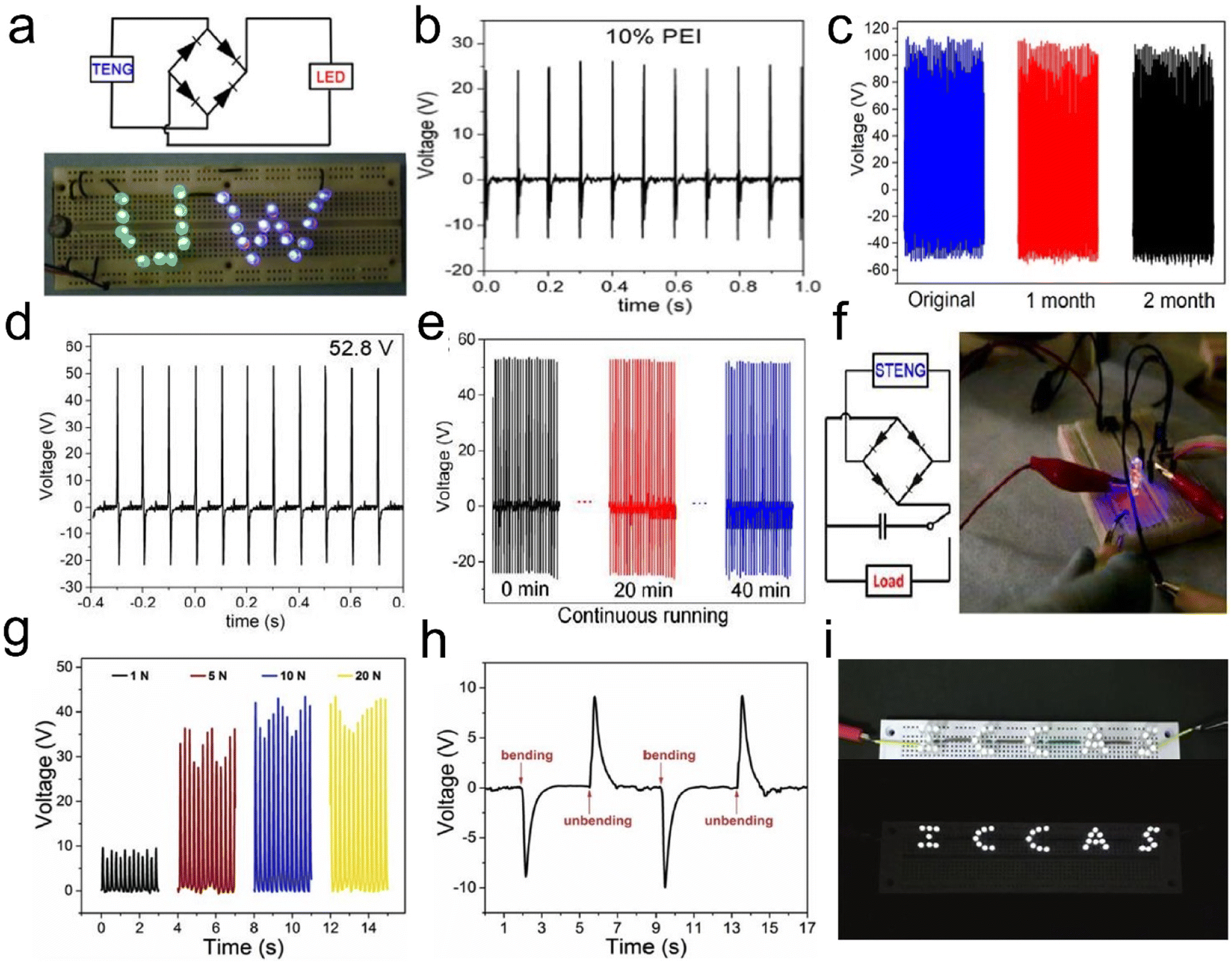 | ||
| Fig. 17 Linear superposition tests and storage of electrical energy generated by 3D fibrous aerogel based TENGs and its application for driving a commercial LED. (a) Twenty-six green and blue LEDs were instantly turned on by a mini TENG. (b) Open circuit voltage of a cellulose nanofibril aerogel and cellulose nanofibril/PEI aerogel with 10% PEI. (c) Output performance stability test for the TENG over two months. Reproduced with permission.128 Copyright 2018, Elsevier. (d) Triboelectric output voltage for silk aerogels prepared using silk fibroin solutions with a concentration of 2%. (e) Output voltage of STENGs in continuous running for 40 min. (f) Lighting of two LEDs using a 10 μF capacitor charged by a STENG. Reproduced with permission.129 Copyright 2018, American Chemistry of Society. (g) PBOA/PEO TENGs were connected with a resistor (1 GΩ), and the pulse voltage on the resistor generated by the bending and unbending of fingers was recorded. (h) The open-circuit voltage and the short-circuit current density of PBOA/PEO TENGs. (i) Photographs of LED bulbs are lit by PBOA/PEO TENGs. Reproduced with permission.133 Copyright 2019, Elsevier. | ||
TENGs have been designed as power supply systems or self-powered sensors for applications in our surrounding areas at ambient temperature. However, their applications under harsh conditions, such as high-temperature environments in thermal power fields and aerospace, are still challenging. The positive tribo-materials of TENGs mainly include metals, carbon, and polymers, some of which may meet the requirements of fire resistance and thermal stability. By comparison, the negative tribo-materials of TENGs are mainly composed of polymeric materials, which become challenges for application under extreme conditions. For example, polytetrafluoroethylene (PTFE), as the most widely used negative tribo-material, will degrade into highly toxic substances above 400 °C or under the exposure to fire.131 The operating temperature of PDMS, another commonly used negative tribo-material, is less than 200 °C. Hence, it is important to develop negative tribo-materials with high-temperature stability and flame resistance for applications of TENGs under extreme conditions. Poly(p-phenylene benzobisoxazole) (PBO) fibers have excellent thermal and mechanical performance, fire resistance, and a limiting oxygen index as high as 68, which is over twice that of aramids.132 Qian et al.133 first reported PBO aerogels (PBOAs) as the negative tribo-materials in TENGs. The resultant TENGs showed a maximum open circuit voltage, short-circuit current density, and charge density of 40 V, 2.9 mA m−2 and 72 μC m−2 (Fig. 17g and h), respectively. The device could light 36 LED bulbs and charge the capacitor to 10 V within 250 s (Fig. 17i). The device can also be used as a self-powered, highly sensitive sensor for monitoring human motion and even slight collisions with an impulse of only 3 μN s.
3.5 Supercapacitors
Supercapacitors are attracting considerable research interest as electrochemical energy storage devices.134 The capacitance of supercapacitors mainly comes from the surface charge separation at the electrode/electrolyte interface (e.g., electrochemical double layered capacitive behavior) and surface faradaic redox reactions (e.g., pseudocapacitive behavior).135,136 Carbon/graphite materials have excellent electrochemical double-layered capacitive behavior, while transition metal oxides, conductive polymers, and carbon materials doped with heteroatoms exhibit pseudocapacitive behavior.137–139 Recently, carbon-containing CNT and graphene aerogels have been considered the most promising electrode materials for supercapacitors because of their combined advantages of a large internal surface area, small pore size, light weight, good electrical conductivity, and high mechanical as well as chemical stability.140,141 The 3D interconnected architecture of aerogels can shorten the transport distances for ions and provide a consecutive pathway, therefore allowing for fast electron transport. Lai et al.142 reported a novel carbon aerogel with a cellular structure, consisting of 1D oxidized polyacrylonitrile (o-PAN) derived carbon nanofibers and 2D PI originated carbon sheets. The interconnected o-PAN/PI (oPP) carbon aerogel possessed low density but enhanced mechanical strength, which could not only act as a versatile adsorbent but also as an ideal template for in situ growth of MnO2 nanosheets to obtain oPP@MnO2 hybrid carbon aerogels (Fig. 18a). The hybrid carbon aerogel had a rectangular CV curve with the largest proportions (Fig. 18b), reflecting excellent rate stability. Besides, the oPP-33.3@MnO2-2h hybrid carbon aerogel showed a high retention of 92.4% after 5000 cycles (Fig. 18c), indicating excellent long cycling stability. The successful fabrication of oPP carbon aerogels has expanded the traditional electrospun lamellar membranes to 3D aerogels, providing a new strategy for developing nanofiber-based materials in energy storage toward energy storage and environmental protection applications. Xia et al.143 reported a flexible electrode based on carbon fiber-reinforced cellulose nanofiber/multiwalled carbon nanotube-hybrid aerogels (CF-CNF/MWCNT-HAs). The 3D porous structure, excellent conductivity, binder-free nature, and high strength the CF-CNF/MWCNT-HAs enabled it to serve as a powerful platform for constructing flexible electrodes with good capacitive performance. The as-prepared CF-CNF/MWCNT/MnO2 positive electrode and CF-CNF/MWCNT/active carbon (AC) negative electrode displayed remarkably high areal-specific capacitances (1745 and 1273 mF cm−2 at a current density of 1 mA cm−2, respectively). Chen et al.144 developed a low-cost, green, sustainable, and scalable approach to synthesize lightweight, highly porous, 3D interconnected N-self-doped carbon nanofiber aerogels (NCNFAs) with a silk cocoon-like node network by in situ growth of ZIF-8 nanocrystals on BC (PVA and acrylic acid (AA)). The CV curves for the NCNFAs had a roughly rectangular shape, including two apparent humps due to the pseudocapacitive effect (Fig. 18e). To show the practical application of the symmetrical supercapacitor, an LED was powered by two supercapacitors in series (inset in Fig. 18f). Furthermore, the all-sold-state symmetrical supercapacitor showed excellent capacitance retention, retaining 91% of the initial value after 5000 galvanostatic charge/discharge cycles.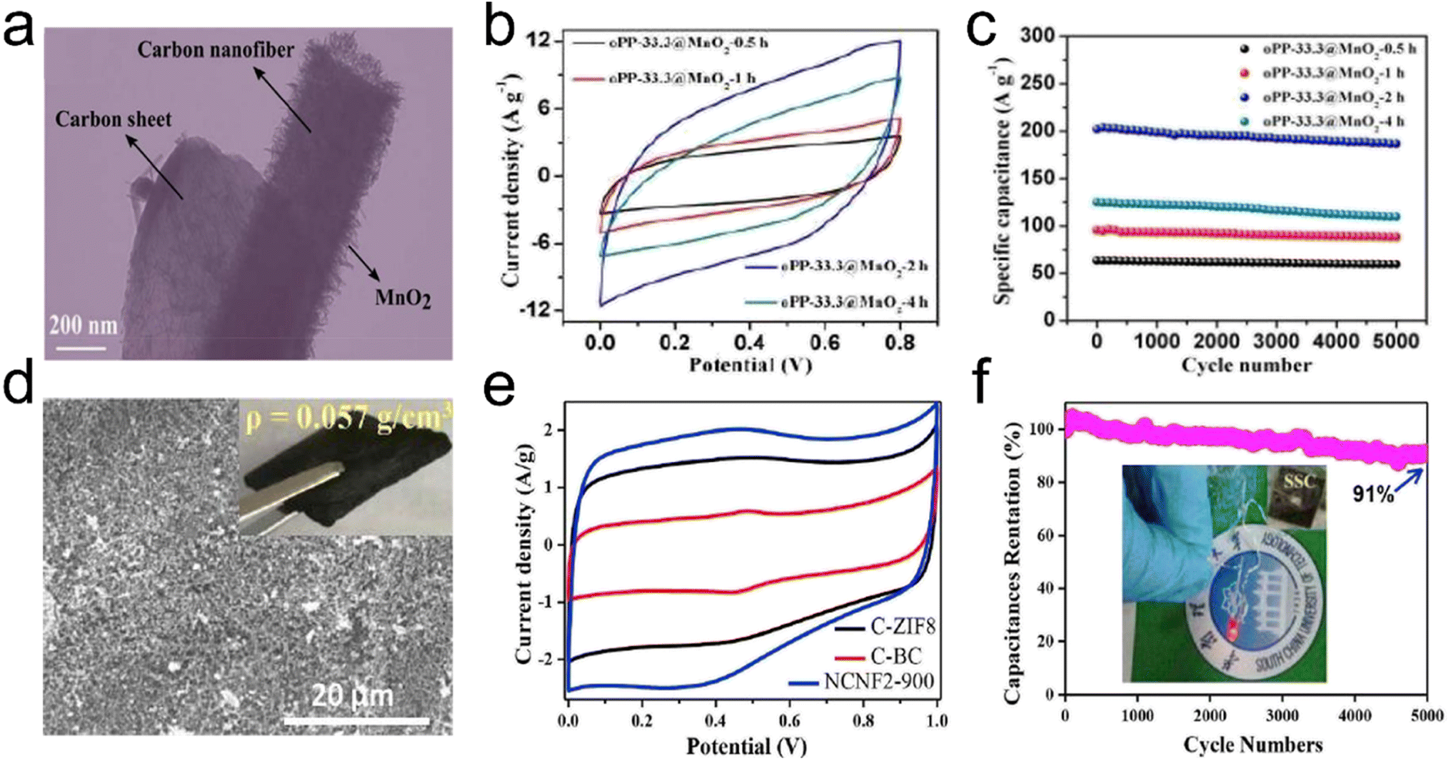 | ||
| Fig. 18 3D fibrous aerogels as electrode materials for supercapacitors. (a) TEM image of an oPP-33.3@MnO2-2h hybrid carbon aerogel. (b) CV curves for oPP-33.3@MnO2-xh hybrid carbon aerogels at a scan rate of 50 mV s−1 (where x = 0.5, 1, 2, and 4, respectively). (c) Cycling stability of oPP-33.3@MnO2-xh hybrid carbon aerogels at a scan rate of 50 mV s−1. Reproduced with permission.142 Copyright 2017, Royal Society of Chemistry. (d) SEM image of NCNFAs. (e) CV curves at 10 mV s−1 of the NCNFA electrode. (f) The symmetrical supercapacitor device measured at 2.5 A g−1 for 5000 cycles, and the inset graph shows a LED powered by the two in series. Reproduced with permission.144 Copyright 2019, Elsevier. | ||
Besides, to further enhance the performance of 3D structures as supercapacitor electrode materials suitable pores are made in carbon nanofibers by chemical/physical activation. The activation process is promisingly beneficial to form nanopores and mesopores in nanofibers, which are desired for supercapacitor applications. Specifically, nanopores would lead to a high specific surface area, thereby benefitting the large capacitance, while mesopores would provide enhanced electrolyte penetration for high power density.145 Another method is to develop 3D structures from transition metal oxide/sulfide nanofibers and conducting polymer nanofibers. Zhang et al.146 developed a 3D highly conductive and elastic electrospun PAN/PVP based cellulose nanofiber aerogel (PVP as a solder to weld adjacent nanofibers) by freeze drying, carbonization, and CO2 activation as a supercapacitor anode material. During the CO2 activation at 900 °C, a fraction of carbon was burned off in the presence of CO2 at the high temperature, resulting a high specific surface area of 437.2 m2 g−1. The activated 3D anode material exhibited a high specific capacitance of 300 F g−1 at 0.3 A g−1. Furthermore, the cellulose nanofiber surfaces were decorated with CNTs with the catalyst of metallic Co NPs, which were oxidized in situ to Co3O4 NPs. The hybrid aerogel as a hierarchical cathode showed a high specific capacitance of 2376 F g−1 at 1 A g−1. By assembling the activated cellulose nanofiber aerogel as the anode and the hybrid aerogel as the cathode, the asymmetric supercapacitor exhibited a considerably high energy density of 48.1 W h kg−1 at 780.2 W kg−1.
3.6 Electromagnetic interference shielding
Electromagnetic pollution has become a serious environmental issue due to the rapid development of various electronic devices and communication systems.147 This problem of electromagnetic interference (EMI) not only threatens human health seriously but also affects the reliability and lifetime of sensitive electronic devices and systems. Therefore, it is desired to develop high-performance EMI shielding materials with light-weight and strong EM wave absorption ability.147–149 Among EMI shielding materials, 3D fibrous aerogels with an interconnected network structure are known as a remarkable candidate to provide excellent EMI shielding, which not only provide a high specific surface and low density, but also have rich holes, which could enhance the dissipation of microwave energy in EMI shielding behavior.150 Until now, various functional materials have been incorporated into 3D fibrous aerogel systems with low density and high porosity, including graphene, CNTs, MXene, and metal nanomaterials.151,152 Lu et al.153 developed a micro-porous structure MXene/ANF hybrid aerogel (Fig. 19a) through a freeze-drying approach. With increasing MXene (Ti3C2Tx) loading, Ti3C2Tx/ANF hybrid aerogels retained high electrical conductivity and efficient shielding capacity, whose EMI shielding effectiveness and specific EMI shielding effectiveness reached ∼56.8 dB and 3645.7 dB cm2 g−1 at a thickness of 1.9 mm in the X-band (Fig. 19b and c). Huang et al.154 designed and prepared CTAB modified CNT/cellulose aerogels with a scaffold structure by controlling the concentration of cellulose in sodium hydroxide/urea solution, which exhibited a uniform outside surface and high porosity inside the structure. Furthermore, the aerogels showed an EMI shielding effectiveness of ∼20.8 dB and a corresponding specific EMI shielding effectiveness as high as ∼219 dB cm3 g−1 with microwave absorption as the dominant EMI shielding mechanism in the microwave frequency range of 8.2–12.4 GHz at a density as low as 0.095 g cm−3.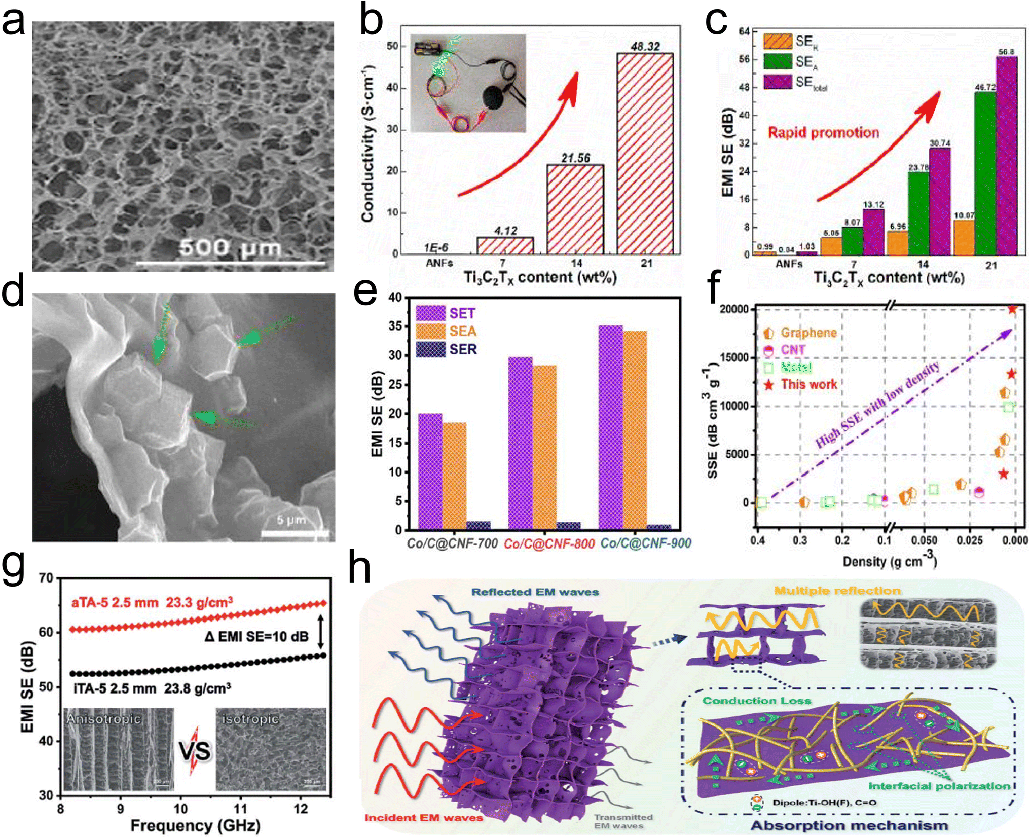 | ||
| Fig. 19 3D fibrous hybrid aerogels for EMI. (a) SEM image, (b) histogram of electrical conductivity, and (c) comparison of microwave reflection (SER) and microwave absorption (SEA) of a Ti3C2Tx/ANF hybrid aerogel. Reproduced with permission.58 Copyright 2017, Elsevier. (d) SEM image of the Co/C@/cellulose nanofiber aerogel. (e) Average SET, SEA, and SER values in the X-band of Co/C@cellulose nanofiber aerogels with various temperatures. (f) Comparison of the shielding performance of any aerogels/foams/sponges ever reported. Reproduced with permission.76 Copyright 2020, Elsevier. (g) A comparison of the anisotropic and isotropic Ti3C2Tx/ANF aerogel. (h) EMI mechanism of the anisotropic Ti3C2Tx/ANF aerogel. Reproduced with permission.150 Copyright 2022, Royal Society Chemistry. | ||
3D CNFAs prepared by high-temperature pyrolyzing biomass or polymer aerogels have attracted extensive academic interest and work efficiently as EMI shielding materials based on their excellent performance of ultralow density, prominent electrical conductivity, large specific surface area, and unique 3D carbon skeleton architecture. The abundant conjugate aromatic structure in the backbone endowed the ANF-derived carbon aerogel film with a high conductivity of 1029.5 S m−1. Remarkably, the high electrical conductivity, as well as the 3D porous skin-core structure, which not only constructs the interconnected electron transmission paths but also significantly extends the propagation path of electromagnetic waves, endowed the carbon aerogel film with a high EMI shielding effectiveness (SE) of 41.4 dB at low density (54.4 mg cm−3) and thin thickness (162 mm) with a high specific shielding effectiveness (SSE/t) of up to 47122.6 dB cm2 g−1. Fei et al.149 reported a 3D ultralight Co/C@cellulose nanofiber aerogel consisting of interconnected carbon sheet networks embedded with Co/C nanoparticles (Fig. 19d), featuring superior electrical conductivity, low specific weight, and outstanding EMI shielding. The performance greatly depends on the carbonization temperature, which affects the graphitization degree and magnetic variation. The Co/C@cellulose nanofiber aerogel at a calcination temperature of 900 °C achieved the highest effectiveness of 35.1 dB at a density of only 1.74 mg cm−3, with a good specific SE of 20172.4 dB cm3 g−1 (Fig. 19e and f). Wan et al.148 used pyrolyzed cellulose nanofiber aerogels as substrates to support some functional materials (e.g., α-FeOOH, α-Fe2O3, and polypyrrole) for enhancing the EMI shielding performances of the carbonized composite aerogels. The composite carbon aerogels exhibited a highest SET of ∼39.4 dB, which was several times higher than that of the individual component. An adsorption-dominant shielding mechanism was ascribed to a more effective complementarity between dielectric loss and magnetic loss from conductive and magnetic fillers well-distributed inside the carbonized porous conductive fibrous network of the aerogel, which was good for higher EM wave absorption and alleviating the secondary radiation. These carbonized CNFAs have become important parts for the construction of EMI shielding materials.
Besides, constructing an anisotropic fibrous aerogel is considered as a promising strategy for improving EMI shielding performances. Compared with the incomplete conductive network in a conventional isotropic aerogel, the anisotropic aerogel was endowed with a macroscopic ordered conductive network through the design of an anisotropic structure. The “cell wall” structure connecting the ordered structures not only optimized the integrity of the aerogel conductive network, but also increased the impedance mismatch interface and improved the multiple reflection efficiency of electromagnetic waves. Typically, Zhang et al.150 prepared an ultralight, conductive Ti3C2Tx/ANF anisotropic aerogel by directional freezing and freeze-drying, which not only endowed it with excellent compressibility and superelasticity, but also built a macroscopic conductive network, thus increasing the impedance mismatch interface, and ensuring the EMI shielding performance of the device. At an ultra-low Ti3C2Tx content (0.58 vol%), the conductivity of the Ti3C2Tx/ANF anisotropic aerogel reached a maximum of 854.9 S m−1 and the EMI SE reached 65.5 dB (Fig. 19g), which was the best efficiency value of an aerogel based on ANFs so far. Fig. 19h briefly shows the mechanism of the Ti3C2Tx/ANF anisotropic aerogel achieving high shielding performance. Based on directional freezing, ordered channels and array “cell wall” structures were formed in the aerogel, which introduced more impedance mismatch interfaces, thereby enhancing the multiple reflections of internal electromagnetic waves. Moreover, the integrated conductive network was formed with a long-range ordered anisotropic structure through the two-dimensional MXene sheet, resulting in a huge amount of electron migration, energy dissipation into heat, and conductive loss.
3.7 Adsorption of heavy metal ions and organic dyes
Worldwide water pollution and the scarcity of clean drinking water have led to a strong need for the development of energy-saving and cost-efficient water purification technologies.155,156 Some heavy metals and organic dyes are a serious cause of concern due to their toxic effect on human beings, the aquatic life, and the ecosystem. Adsorption is an effective technique to remove these contaminants. 3D fibrous aerogels or aerogels are being explored as a novel adsorbent material for water treatment due to their attractive properties of a high specific surface area, large porosity, high adsorption capacity, and ease of recycling without secondary pollution. Typically, cellulose-based aerogels known as bio-aerogels are a group of organic aerogels with superior adsorption properties. Compared to traditional inorganic aerogels (e.g., silica), bio-aerogels are reported to have high strength and do not break under compression with plastic deformation up to 80% strain before pore wall collapse.157 Moreover, the production of aerogels from cellulose does not involve toxic compounds. She et al.158 developed ecofriendly and recycled cellulose nanofiber aerogel adsorbents which were cross-linked by PVA and AA. The heavy metal ions were adsorbed on the cellulose nanofiber–PVA–AA adsorbents efficiently, and the maximum adsorption capacities for Cu2+ and Pb2+ approached 30.0 mg g−1 and 131.5 mg g−1, respectively. Xu et al.159 developed an ultralight electrospun cellulose aerogel (UECA) with high porosity (99.57%), low density (6.45 mg cm−3), hydrophobic surface features (with a water contact angle of 141.2°), and excellent elasticity. The prepared UECA possessed super-high absorption capacity towards organic compounds (e.g., oil and organic solvents) due to high porosity, low density, and desired surface hydrophobicity (Fig. 20a–c). Besides, due to the abundance of hydroxyl groups on native cellulose, they can be easily chemically modified to create improved versions of cellulose-based aerogels with enhanced adsorption ability, mechanical strength and the ability to re-generate for repeated use. Zhu et al.160 prepared fibrous MOF hybrid aerogels through the sequential processes of ionic gelation, template synthesis of MOFs, and freeze-drying. When exposing to multivalent metal ions (e.g., Zn2+, Cu2+, Co2+, etc.), carboxylic cellulose nanofibers would interact ionically with metal ions. These ionic interactions served as ionic cross-linkers and favored a “phase transition” from colloidal cellulose nanofibers to homogeneous fibrous MOF layers. Cellulose nanofibers seemed to be physically cross-linked by H-bonding and physical entanglement of cellulose nanofibers as well as strong interactions between MOF crystals and cellulose nanofibers. The resultant MOF aerogels (e.g., HKUST-1, ZIF-8, ZIF-67, etc.) all demonstrated excellent adsorption performances towards organic dyes such as Rhodamine B, Methyl Violet, and Methylene Blue. Similarly, our group161,162 reported that the in situ growth of nano-porous materials (e.g., MnO2, ZIF-67, etc.) on the ANF aerogel framework could improve the adsorption capacity of heavy metal ions (Pb2+, Cu2+, and Cr6+) and organic dyes (methyl orange and crystal violet). He et al.163 developed a PI amine dendrimer aerogel based on ANFs through an effective method, which showed a specific area larger than the ANF aerogel by 38.1% due to the formation of polyamide amine dendrimer nanofibers bridging between ANFs. Besides, electrospun polymer nanofiber-based aerogels are considered a promising absorbent due to their fantastic porosity characteristics. Xue et al.164 reported novel fibrous aerogels prepared by freeze-drying technology and cross-linking with epichlorohydrin (ECH) via short PAN/PEI nanofibers, showing high mechanical stability and good mass transfer performance. The adsorption capacities of these prepared fibrous aerogels reached 242.71 mg g−1 (Cu2+), 214.14 mg g−1 (Cr6+), 258.36 mg g−1 (As5+), and 183.06 mg g−1 (anionic dye methyl orange). The adsorbent still kept considerable adsorption efficiency after seven adsorption–regeneration cycles.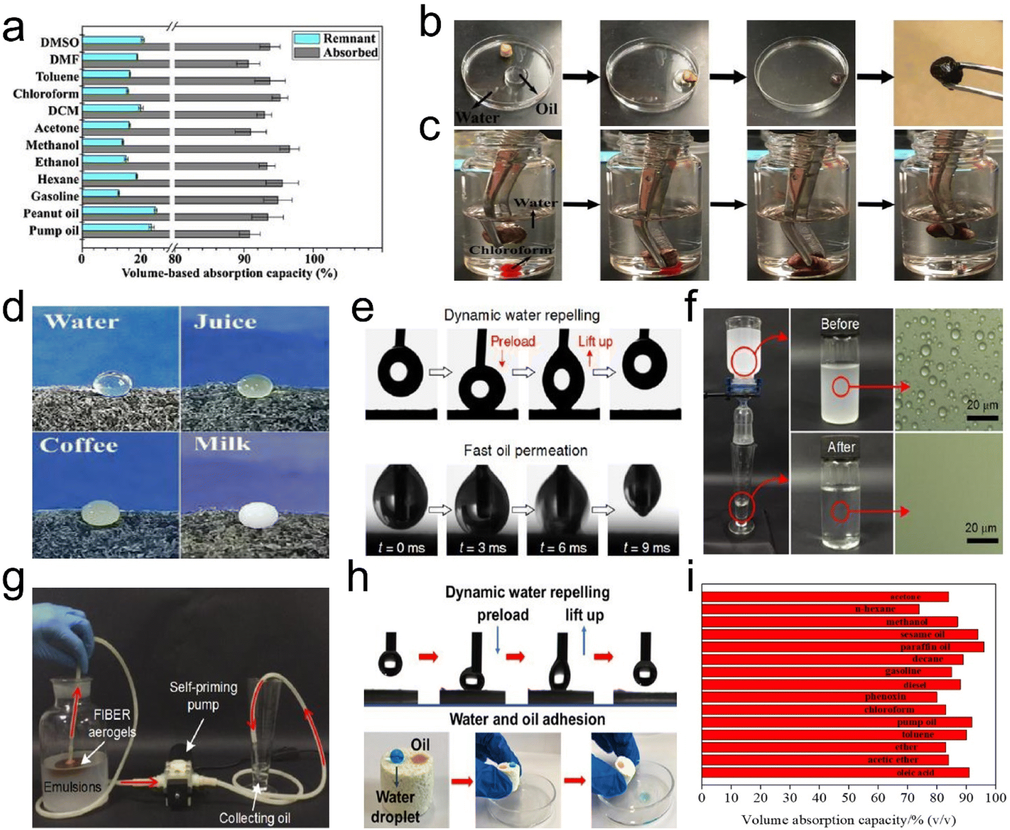 | ||
| Fig. 20 Various functions of 3D fibrous aerogels for applications in water treatment. (a) Volume-based absorption capacities of a UECA on different organic compounds. (b) Removing pump oil from the surface of water. (c) Collecting chloroform (containing the dye of Sudan I) from the bottom of water. Reproduced with permission.159 Copyright 2019, Elsevier. (d) Digital pictures showing the state of different liquid droplets on the surface of PINF/MXene hybrid aerogels. Reproduced with permission.171 Copyright 2021, Wiley-VCH. (e) Photographs of dynamic measurements of water adhesion (top) and oil permeation (bottom) on the surface of the aerogels (2 wt% SiO2 NPs). (f) Separation apparatus with the facile gravity-driven separation of water-in-oil emulsions using the aerogels and the microscopic images of emulsions before and after separation. (g) Photograph of the oil collection apparatus continuously collecting pure oil from water-in-oil emulsions. Reproduced with permission.172 Copyright 2021, American Chemical Society. (h) Photographs of the dynamic measurements of water adhesion (top) and photograph of water and oil droplets on the aerogel surface (bottom). Reproduced with permission.173 Copyright 2021, American Chemical Society. (i) Absorption efficiency of the carbon aerogels for various organic liquids. Reproduced with permission.176 Copyright 2021, Elsevier. | ||
3.8 Oil–water separation
Oil spill from different sources, for example, from tankers or oil drilling, is regarded as one of the most severe water pollution problems. Efficient ways of separation of oil from water are therefore required to protect the marine environment and are a large challenge. Conventional methods such as oil skimmers, centrifuges, depth filters, sedimentation, and flotation are useful for the separation of immiscible oil/water mixtures, but are not effective for emulsified oil/water mixtures.165,166 Membrane-based technologies, such as ultrafiltration which selectively allows materials of certain sizes to pass through the membrane pores on the basis of the size-sieving effect, have been successfully used to separate various industrial emulsions. However, these pressure-driven separation membranes suffer from low flux and energy consumption due to a small pore size (<0.3 μm).167,168 Alternatively, interfacial super-wetting 3D fibrous aerogels with high porosity and tunable pore structures are generally regarded as effective media to selectively remove oil and water.169 The developed interfacial super-wetting 3D fibrous aerogels are mainly divided into two different types due to their surface wettability and functions in handling different oil/water mixtures: (i) superhydrophobic–superoleophilic aerogels are used to absorb oil; (ii) superhydrophilic–underwater superoleophobic aerogels are used to eliminate the layered oil/water mixture and oil-in-water emulsions.170The general methods to develop interfacial super-wetting 3D fibrous aerogels mainly include creating hierarchical structures (nano/microstructure) and surface chemistry modification. Typically, the secondary surface morphology (e.g., wrinkled structure, nano/microstructure, branched structure, etc.) on the nanoscale is usually considered as one of the most important factors to the surface properties, which can endow 3D fibrous aerogels with excellent oil–water separation performances. For example, Liu et al.171 prepared PINF/MXene hybrid aerogels with a typical “layerstrut” bracing hierarchical fibrous cellular structure. The surface of the hybrid aerogels immersed in water displayed strong light reflection, which was caused by the trapped air layer that led to total light reflection, preventing it from being wetted effectively. And the various liquid droplets, including water, juice, coffee, and milk, could retain a spherical shape on the surface of hybrid aerogels, demonstrating the hydrophobicity of the hybrid aerogels (Fig. 20d). The hybrid aerogels exhibited superior oil/water separation properties such as high adsorption capacity (55.85 to 135.29 g g−1) and stable recyclability due to its hydrophobicity and robust hierarchical porous structure. Si et al.172 developed superelastic and superhydrophobic PAN/SiO2 fibrous aerogels with a hierarchical cellular structure. By the inclusion of hydrophobic SiO2 NPs, the morphologies of the resultant fibrous aerogels were changed by creating nanoscaled rough structures on the surface of nanofibers. With increasing SiO2 NP concentrations, the average pore size of aerogels quickly decreased from 18.9 to 4.2 μm; meanwhile, the specific surface area of fibrous aerogels increased dramatically from 2.66 to 76.54 m2 g−1. The PAN/SiO2 fibrous aerogels exhibited superhydrophobic–superoleophilic wettability, which could separate surfactant-stabilized water-in-oil emulsions, solely using gravity, with a high flux that was several times higher than that of commercial filtration membranes driven by external pressure (Fig. 20e–g). Besides, Shen et al.173 reported novel hybrid PI fibrous aerogels by reconstructing intrinsically lamellar-deposited electrospun nanofibers. The porous fibrous aerogels were further modified using trichloromethylsilane (TCMS) to generate silicone nanofilaments (SiNFs) on the surface of the PI nanofibers, which could enhance the hydrophobicity (water contact angle 151.7°) of the fibrous aerogels. SiNF-coated fibrous aerogels could collect a wide range of oily solvents with high absorption capacities up to 159 times their own weight (Fig. 20h). Similarly, Tai et al.174 reported self-assembled superhydrophobic electrospun carbon–silica nanofiber aerogels, and the prepared aerogels exhibited superhydrophobicity with the average water contact angle being 155.4°. In contrast, a commercial polyurethane aerogel would sink below the water surface owing to its hydrophilicity. Finally, the prepared aerogels exhibited high sorption capacities of 65 to 140 times their own weight with larger sorption capacities for liquids of higher density (e.g., benzyl alcohol) and cyclic distillation performance.
The surface chemistry modification of 3D fibrous aerogels can be tubed using low or high surface energy molecules with the aid of common techniques including dip-coating, solution immersion, chemical vapor deposition (CVD), carbonization, and so on.170 For instance, Chhajed et al.167 utilized stearic acid chloride (SAC) as the dip-coating material to modify cellulose nanofiber aerogels, and the surface modification of cellulose nanofiber aerogels was carried out by esterification reaction dip coating. The SAC conjugated aerogels combined both superhydrophobic and oleophilic characteristics showed a contact angle of ∼159° and ∼0° with water and oil, respectively. The prepared aerogels were found to be very efficient in separating a series of oil/water mixtures and various organic solvents with excellent selectivity and recyclability. Qiao et al.168 reported a superhydrophobic, elastic, and anisotropic cellulose nanofiber aerogel. Specifically, directional freeze-drying, soaking in polydimethylsiloxane (PDMS) solution, and heat treatment were applied to obtain anisotropic hybrid aerogel sheets and blocks with superhydrophobicity and high elasticity. The hybrid fibrous aerogels could realize continuous oil/water separation by filtration with a flux up to 2800 L m−2 h−1 and a separation efficiency of 99.9%. Deuber et al.175 prepared pullulan/PVA fibrous aerogels modified using trichloro(octyl)silane (TOS) via a CVD method, which exhibited a hydrophobic surface and showed a high absorption capacity of 430 m3 m−3. Long et al.176 developed a hydrophobic carbon aerogel derived from deep eutectic solvent (DES) modified cellulose nanofibers under a low carbonization temperature of 350 °C. The as-prepared carbon aerogel showed a high volume absorption capability for organic pollutants and oils ranging from 74% to 95% (Fig. 20i). Besides, Zhou et al.177 reported an anisotropic lamellar hydrophobic and lipophilic graphene/PVA/cellulose nanofiber carbon aerogel prepared by directional freeze-drying and carbonization processes. The directional freeze-drying process led to a lamellar interpenetrated 3D porous structure, which endowed the carbon aerogel with high adsorption capacity (155–288 times of its weight), good compressibility (95% recovery after repeating 15 cycles at 50% strain in parallel to the freezing direction) and recyclability (oil retention rate reached 88.8% after 10 absorption–compression cycles).
3.9 Interfacial solar vapor generation
Interfacial solar vapor generation is intensely pursued as one of the most promising technologies to provide portable clean water solution for water-stressed areas.178–180 With carefully tailored solar absorbers, the energy of solar irradiation can be absorbed and converted into heat, which can be utilized to vaporize water in the interfacial area of water and air.181 Aerogels with highly porous structures had several intrinsic superiority ideal for interfacial solar vapor generation (Fig. 21a). First, the fibrous networks of the aerogels can reduce the light reflection and improve light scattering inside pores of aerogels, promoting the absorption of solar energy. Second, the highly porous features can confine the generated heat in the interfacial region of water and air and reduce conduction heat loss.182 Third, the interconnected pores inside aerogels can offer plenty of channels for fast water transportation and vapor escape, which endow aerogels with lightweight properties and make aerogels naturally float on the water surface without any support.182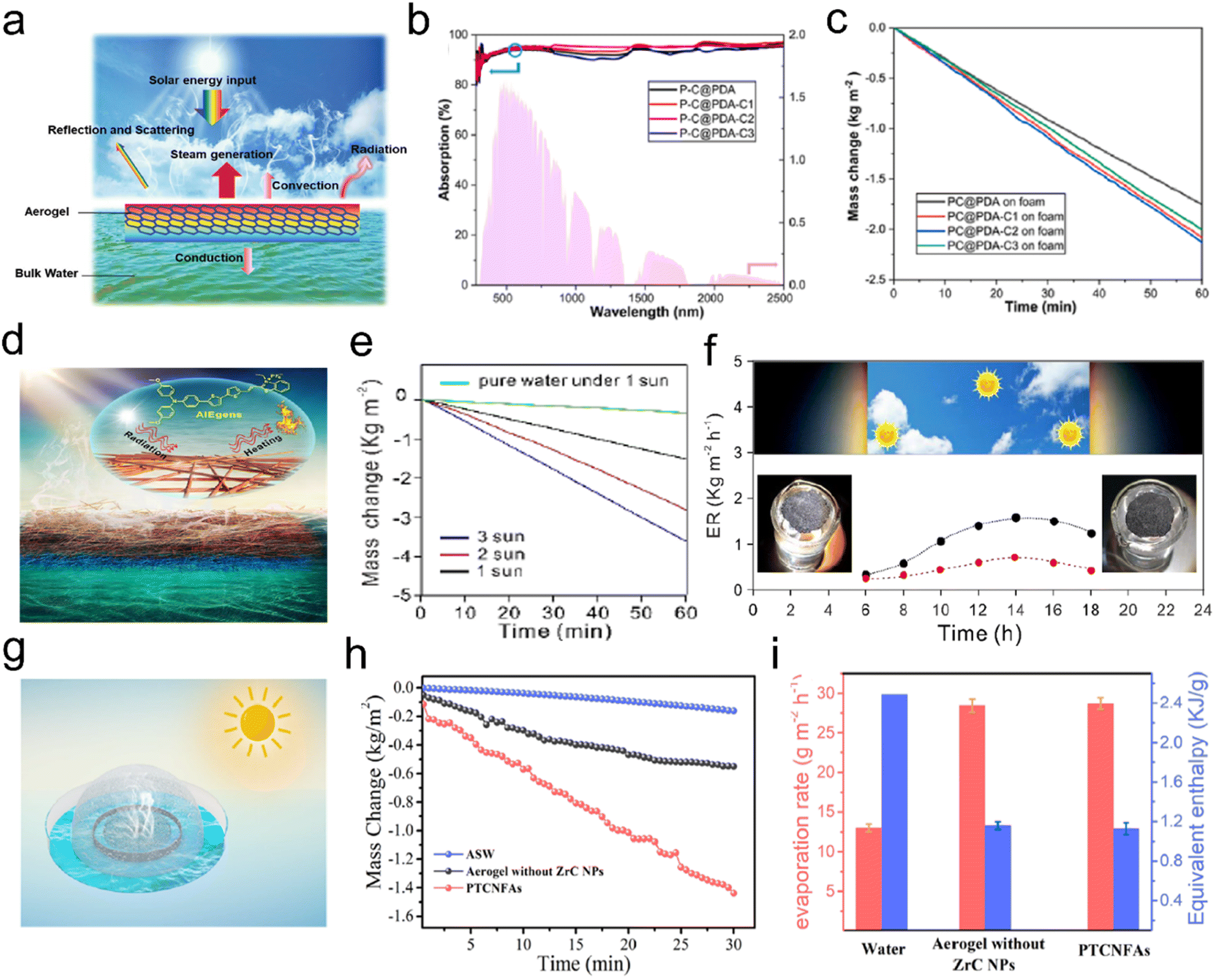 | ||
| Fig. 21 3D fibrous aerogels applied in interfacial solar vapor generation. (a) Schematic illustration of tailoring aerogels for interfacial solar vapor generation. Reproduced with permission.181 Copyright 2019, Wiley-VCH. (b) UV-vis-NIR absorption spectra of different fibrous aerogels and spectrum of AM 1.5 G. (c) Mass change of different aerogels standing on foam. Reproduced with permission.183 Copyright 2022, Elsevier. (d) Schematic of solar steam generation. (e) The mass loss of water over time under different illumination intensities. (f) Evaporation rate of 3D fibrous aerogels (black spots) at 6:00 to 18:00 for over a day (red spots show the evaporation rate of a blank beaker without 3D fibrous aerogels). The inset shows the photograph images of the 3D fibrous aerogels at the beginning and end under irradiation of sunlight for one day, and no salt deposition was observed. Reproduced with permission.184 Copyright 2020, American Chemical Society. (g) Schematic of the solar vapor generation device which is based on the PTCNFAs under 1 sun irradiation. (h) Mass change of evaporated vapor over time. (i) Water evaporation rate ratio under dark conditions and the calculated equivalent enthalpy. Reproduced with permission.185 Copyright 2020, American Chemical Society. | ||
In the past few years, 3D fibrous aerogels have been widely developed for interfacial solar vapor generation, achieving improved energy conversion efficiency. Qin et al.183 prepared luffa-inspired electrospun PAN/CNT nanofiber-based aerogels with a hierarchical pore structure using an eco-friendly crosslinking and easy freeze-drying approach. The fibrous aerogels combined the synergistic photothermal effect of polydopamine (PDA) and CNTs, leading to a high light absorption of 94.8% (Fig. 21b). Furthermore, the 3D interconnected structure formed from nanofibers greatly reduced the enthalpy of vaporization. The prepared fibrous aerogels showed a fast evaporation rate of 2.13 kg m−2 h−1 and a high solar-vapor conversion efficiency of 94.5% under one sun (Fig. 21c). Tang et al.184 demonstrated 3D fibrous aerogels by doping an aggregation-induced emission (AIE) photothermal molecule, which could float on the water surface and continuously self-pump water (Fig. 21d). The prepared 3D fibrous aerogels had a high evaporation rate (1.43 kg m−2 h−1), solar-to-vapor conversion efficiency (86.5%) under irradiation of 1 sun, and a high evaporation rate (10.9 kg m−2 h−1) under natural sunlight (Fig. 21e). Besides, the outdoor experiment on the roof was carried out from 05:00 to 19:00 under natural sunlight. As depicted in Fig. 21f, the evaporation rate of the 3D fibrous aerogels at 06:00 was only 0.17 kg m−2 h−1, which agrees well with the dark-condition data. The average seawater evaporation rate was calculated to be 1.09 kg m−2 h−1, revealing an enhanced evaporation, compared with that under blank test conditions. Wang et al.185 reported photothermal conversion fibrous aerogels (PTCNFAs) with vertically aligned microchannels as a solar steam generator (Fig. 21g). Benefiting from the excellent mechanical properties, high water-transfer rates, and outstanding photothermal properties, the PTCNFAs were more convenient in application and exhibit an efficient solar water evaporation rate (2.89 kg m−2 h−1) (Fig. 21h), while the energy efficiency under 1 sun was about 90.3% (Fig. 21i). Our group186 fabricated an all-in-one solar-driven interfacial evaporator from a hybrid fibrous aerogel of ANFs, CNTs, and AuNPs. The fibrous aerogels showed a high evaporation rate of 1.53 kg m−2 h−1 and an evaporation efficiency of 91.3% under 1 sun irradiation. Moreover, the evaporator demonstrates a high purification capacity for wastewater with dyes and heavy metal ions. These research studies all demonstrate that 3D fibrous aerogels may provide a novel structured photothermal conversion material for the solar steam generation application to meet the demands of environmentally friendly treatment of seawater or sewage.
4. Summary and future outlook
In the past few decades, a large number of 3D fibrous aerogels composed of versatile nanofibers have attracted widespread attention and have been extensively researched due to their promising future in a wide range of applications. Great achievements have been made in the research on 3D fibrous aerogels through continuous efforts. Up to now, many approaches have been proposed to fabricate different types of 3D fibrous aerogels with designed structures, mainly involving electrospinning, solution blow spinning, freeze-drying, thermally induced self-agglomeration, and carbonization. Based on the combined merits of ultra-low density, a high specific area, large porosity, mechanical stability, and controllable physical/chemical characteristics, the developed 3D fibrous aerogels have been widely applied in energy (e.g., pressure sensors, triboelectric nanogenerators, supercapacitors, electromagnetic interference shielding, etc.) and the environment (e.g., air filtration, thermal insulation, oil–water separation, interfacial solar vapor generation, etc.). Therefore, we review the advanced research and progress from the preparation methods to the multifunctional applications of 3D fibrous aerogels.Despite the current huge advances, many momentous issues and challenges still remain and need to be further resolved by future enormous efforts. First, although the way of utilizing nanofibers as building blocks to construct 3D fibrous aerogels has improved the mechanical strength of monolithic materials to a certain extent, the mechanical strength and fatigue durability are still not strong enough to satisfy the requirements of highly effective practical applications, and therefore the mechanical properties of 3D fibrous aerogels should be ulteriorly strengthened. Second, the porous structure greatly affects the application performance of 3D fibrous aerogels due to its influences on the mass transfer and mechanical strength properties of 3D fibrous aerogels; however, precisely controlling the porous structure of 3D fibrous aerogels is still a great challenge, which needs to be addressed imminently. Furthermore, most of the fabrication and application research studies of the current 3D fibrous aerogel materials are at the laboratory study level, and thus, large-scale and high-quality production of 3D fibrous aerogels with controlled structures is highly needed. 3D fibrous aerogels are expected to enter the market first in those areas in which they can provide significant performance improvements and create high value.
We anticipate that the summarized preparation methods and multifunctional application study of 3D fibrous aerogels, together with the well-selected references and some personal opinions, will furnish the relevant researchers with some guidance for the further study on the fabrication and application of high-performance 3D fibrous aerogels. Although a lot of challenges want to stop us, we believe that the overall goal of the preparation of multifarious 3D fibrous aerogels with precisely regulated porous structures, excellent mechanical properties, and highly effective performance will be achieved through our relentless searching and continual efforts, and the large-scale application of 3D fibrous aerogels will be achieved in the near future.
Conflicts of interest
The authors declare no conflict of interest.Acknowledgements
We would like to thank the National Natural Science Foundation of China (51603148 and 51873152), Tianjin Science and Technology Project (20YDTPJC01380), and Tianjin Research Innovation Project for Postgraduate Students (2021YJSB224).References
- K. J. D. France, T. Hoare and E. D. Cranston, Chem. Mater., 2017, 29, 4609–4631 CrossRef
.
- V. Rahmanian, T. Pirzada, S. Y. Wang and S. A. Khan, Adv. Mater., 2021, 33, 2102892 CrossRef CAS
- A. C. Pierre and G. M. Pajonk, Chem. Rev., 2002, 102, 4243–4266 CrossRef CAS
- H. Sun, Z. Xu and C. Gao, Adv. Mater., 2013, 25, 2554–2560 CrossRef CAS PubMed
- H. Tetik, Y. Wang, X. Sun, D. Cao, N. Shah, H. L. Zhu, F. Qian and D. Lin, Adv. Funct. Mater., 2021, 31, 2103410 CrossRef CAS
- N. Hüsing and U. Schubert, Angew. Chem., Int. Ed., 1998, 37, 3071–3082 CrossRef
- J. Fricke and A. Emmerling, Adv. Mater., 1991, 3, 10–18 CrossRef
- S. S. Kistler, J. Phys. Chem., 1932, 5, 600–603 Search PubMed
- H. D. Gesser and P. C. Goswami, Chem. Rev., 1989, 89, 765–788 CrossRef CAS
- Y. T. Niu, F. Z. Li, W. X. Zhao and W. Cheng, Nanoscale, 2021, 13, 7430 RSC
- W. Liu, A. K. Herrmann, N. C. Bigall, P. Rodriguez, D. Wen, M. Oezaslan, T. J. Schmidt, N. Gaponik and A. Eychmüller, Acc. Chem. Res., 2015, 48, 154 CrossRef CAS PubMed
- Y. Tang, K. L. Yeo, Y. Chen, L. W. Yap, W. Xiong and W. Cheng, J. Mater. Chem. A, 2013, 1, 6723–6726 RSC
- J. L. Mohanan, I. U. Arachchige and S. L. Brock, Science, 2005, 307, 397–400 CrossRef
- C. Ziegler, A. Wolf, W. Liu, A. K. Herrmann, N. Gaponik and A. Eychmüller, Angew. Chem., Int. Ed., 2017, 56, 13200–13221 CrossRef PubMed
- F. Rechberger and M. Niederberger, Nanoscale Horiz., 2017, 2, 6–30 RSC
- M. B. Bryning, D. E. Milkie, M. F. Islam, L. A. Hough, J. M. Kikkawa and A. G. Yodh, Adv. Mater., 2007, 19, 661–664 CrossRef
- S. M. Jung, H. Y. Jung, M. S. Dresselhaus, Y. J. Jung and J. Kong, Sci. Rep., 2012, 2, 849 CrossRef PubMed
- S. M. Jung, H. Y. Jung, W. Fang, M. S. Dresselhaus and J. Kong, Nano Lett., 2014, 14, 1810–1817 CrossRef CAS
- J. Z. Li, L. L. Wang, L. Li, C. C. Lv, I. V. Zatovsky and W. Han, ACS Appl. Mater. Interfaces, 2019, 11, 8072–8080 CrossRef CAS PubMed
- A. Menzel, K. Subannajui, F. Güder, D. Moser, O. Paul and M. Zacharias, Adv. Funct. Mater., 2011, 21, 4342–4348 CrossRef CAS
- J. T. Schiphorst, M. V. D. Broek, T. D. Koning, J. N. Murphy, A. Schenning and A. C. C. Esteves, J. Mater. Chem. A, 2016, 4, 8676–8681 RSC
- Y. Chen, L. Zhang, Y. Yang, B. Pang, W. Xu, G. Duan, S. Jiang and K. Zhang, Adv. Mater., 2021, 33, 2005569 CrossRef CAS
- D. Li, T. Wu, N. He, J. Wang, W. Chen and L. He, Colloids Surf., B, 2014, 121, 432–443 CrossRef PubMed
- N. Lavoine and L. Bergström, J. Mater. Chem. A, 2017, 5, 16105–16117 RSC
- B. Dong, L. Gwee, D. S. Cruz, K. I. Winey and Y. A. Elabd, Nano Lett., 2010, 10, 3787 CrossRef PubMed
- Y. F. Li, Q. H. Li and Z. C. Tan, J. Power Sources, 2019, 443, 227262 CrossRef
- A. Mohammed Al-Dhahebi, J. Ling and S. G. Krishnan, Appl. Phys. Rev., 2022, 9, 011319 Search PubMed
- D. Li and Y. Xia, Adv. Mater., 2004, 16, 1151–1170 CrossRef
- S. Agarwal, J. H. Wendorff and A. Greiner, Adv. Mater., 2009, 21, 3343–3351 CrossRef
- L. Zhao, H. Y. Wu, W. L. Jiao, X. Yin, Y. Si, J. Y. Yu and B. Ding, Compos. Commun., 2021, 25, 100681 CrossRef
- H. Y. Wu, L. Zhao, Y. Si, S. C. Zhang, J. Y. Yu and B. Ding, Compos. Commun., 2021, 25, 100766 CrossRef
- R. Q. Liu, X. X. Wang, J. Fu, Q. Q. Zhang, W. Z. Song, Y. Xu, Y. Q. Chen, S. Ramakrishnal and Y. Z. Long, Nanomaterials, 2019, 9, 1090 CrossRef PubMed
- Y. Gao, H. F. Xiang, X. X. Wang, K. Yan, Q. Liu, X. Li, R. Q. Liu, M. Yu and Y. Z. Long, Chem. Eng. J., 2020, 387, 124052 CrossRef
- B. Khalid, X. P. Bai, H. H. Wei, Y. Huang, H. Wu and Y. Cui, Nano Lett., 2017, 17, 1140–1148 CrossRef PubMed
- Y. Gao, J. Zhang, Y. Su, H. Wang, X. Wang, L. Huang, M. Yu, S. Ramakrishna and Y. Long, Mater. Horiz., 2021, 8, 426–446 RSC
- J. J. Xue, T. Wu, Y. Q. Dai and Y. N. Xia, Chem. Rev., 2019, 119, 5298–5415 CrossRef PubMed
- S. L. Chen, H. Q. Hou, F. Harnisch, S. A. Patil, A. A. Carmona-Martinez, S. Agarwal, Y. Y. Zhang, S. Sinha-Ray, A. L. Yarin, A. Greiner and U. Schroder, Energy Environ. Sci., 2011, 4, 1417 RSC
- X. P. Zhuang, K. F. Jia, B. W. Cheng, X. Feng, S. J. Shi and B. Zhang, Chem. Eng. J., 2014, 237, 308–311 CrossRef
- S. C. Park, M. J. Kim, K. Choi, J. Kim and S. O. Choi, RSC Adv., 2018, 8, 32470–32480 RSC
- H. L. Wang, S. Lin, S. Yang, X. D. Yang, J. N. Song, D. Wang, H. Y. Wang, Z. L. Liu, B. Li, M. H. Fang, N. Wang and H. Wu, Small, 2018, 14, 1800258 CrossRef PubMed
- G. D. Zhao, H. J. Zhao, X. P. Zhuang, L. Shi, B. W. Cheng, X. L. Xu and Y. Yin, J. Mater. Chem. A, 2021, 9, 3729 RSC
- Z. W. Li, Z. W. Cui, L. H. Zhao, N. Hussain, Y. Z. Zhao, C. Yang, X. Y. Jiang, L. Li, J. N. Song, B. P. Zhang, Z. K. Cheng and H. Wu, Sci. Adv., 2022, 8, e3690 CrossRef
- Y. Huang, J. N. Song, C. Yang, Y. Z. Long and H. Wu, Mater. Today, 2019, 28, 98–113 CrossRef
- Y. X. Hu, B. Luo, D. L. Ye, X. B. Zhu, M. Q. Lyu and L. Z. Wang, Adv. Mater., 2017, 29, 1606132 CrossRef PubMed
- C. Cheng, S. Li, A. Thomas, N. A. Kotov and R. Haag, Chem. Rev., 2017, 117, 1826–1914 CrossRef PubMed
- S. Deville, E. Saiz, R. K. Nalla and A. P. Tomsia, Science, 2006, 311, 5156 CrossRef
- J. T. Schiphorst, M. V. D. Broek, T. D. Koning, J. N. Murphy, A. Schenning and A. C. C. Esteves, J. Mater. Chem. A, 2016, 4, 8676–8681 RSC
- S. Deville, Adv. Eng. Mater., 2008, 10, 155–169 CrossRef CAS
- V. Chabot, D. Higgins, A. Yu, X. Xiao, Z. Chen and J. Zhang, Energy Environ. Sci., 2014, 7, 1564–1596 RSC
- L. F. Chen, Y. Feng, H. W. Liang, Z. Y. Wu and S. H. Yu, Adv. Energy Mater., 2017, 7, 1700826 CrossRef
- S. Nardecchia, D. Carriazo, M. L. Ferrer, M. C. Gutierrez and F. Monte, Chem. Soc. Rev., 2013, 42, 794–830 RSC
- G. Nyström, M. P. Fernández-Ronco, S. Bolisetty, M. Mazzotti and R. Mezzenga, Adv. Mater., 2016, 28, 472–478 CrossRef
- S. M. Jung, D. J. Preston, H. Y. Jung, Z. Deng, E. N. Wang and J. Kong, Adv. Mater., 2016, 28, 1413–1419 CrossRef CAS
- G. Wei and P. X. Ma, Adv. Funct. Mater., 2008, 18, 3566–3582 Search PubMed
- J. Han, C. Zhou, Y. Wu, F. Liu and Q. Wu, Biomacromolecules, 2013, 14, 1529–1540 CrossRef CAS PubMed
- C. Liu, S. Wang, N. Wang, J. Y. Yu, Y. T. Liu and B. Ding, Nano-Micro Lett., 2022, 14, 194 CrossRef CAS
- T. Xu, Y. C. Ding, Z. Wang, Y. Zhao, W. D. Wu, H. Fong and Z. T. Zhu, J. Mater. Chem. C, 2017, 5, 10288–10294 RSC
- F. Deuber, S. Mousavi, M. Hofer and C. Adlhart, ChemistrySelect, 2016, 1, 5595 CrossRef CAS
- Q. X. Fu, Y. Si, C. Duan, Z. S. Yan, L. F. Liu, J. Y. Yu and B. Ding, Adv. Funct. Mater., 2019, 13, 1808234 CrossRef
- Y. Si, X. Q. Wang, C. C. Yan, L. Yang, J. Y. Yu and B. Ding, Adv. Mater., 2016, 28, 9512–9518 CrossRef
- H. F. Qin, Y. F. Zhang, J. G. Jiang, L. L. Wang, M. Y. Song, R. Bi, P. H. Zhu and F. Jiang, Adv. Funct. Mater., 2021, 31, 2106269 CrossRef
- F. Wang, L. Dou, J. W. Dai, Y. Y. Li, L. Q. Huang, Y. Si, J. Y. Yu and B. Ding, Angew. Chem., Int. Ed., 2020, 132, 8362 CrossRef
- L. Wang, M. Y. Zhang, B. Yang, J. J. Tan and X. Y. Ding, ACS Nano, 2020, 14, 10633–10647 CrossRef PubMed
- G. Zu, J. Shen, L. Zou, W. Wang, Y. Lian, Z. Zhang and A. Du, Chem. Mater., 2013, 25, 4757–4764 CrossRef
- T. Xu, J. M. Miszuk, Y. Zhao, H. L. Sun and H. Fong, Adv. Healthcare Mater., 2015, 4, 2237 CrossRef
- T. Xu, Z. P. Liang, B. Ding, Q. Feng and H. Fong, Polymer, 2018, 151, 299–306 CrossRef
- Q. Q. Yao, J. G. L. Cosme, T. Xu, J. M. Miszuk, P. H. S. Picciani, H. Fong and H. L. Sun, Biomaterials, 2017, 115, 115–127 CrossRef PubMed
- J. M. Miszuk, T. Xu, Q. Q. Yao, F. Fang, J. D. Childs, Z. K. Hong, J. N. Tao, H. Fong and H. L. Sun, Appl. Mater. Today, 2018, 10, 194–202 CrossRef PubMed
- X. Zheng, H. Lee, T. H. Weisgraber, M. Shusteff, J. DeOtte, E. B. Duoss, J. D. Kuntz, M. M. Biener, Q. Ge and J. A. Jackson, Science, 2014, 344, 1373–1377 CrossRef PubMed
- D. Wang, H. Y. Peng, B. Yu, K. Q. Zhou, H. F. Pan, L. P. Zhang, M. Li, M. M. Liu, A. L. Tian and S. H. Fu, Chem. Eng. J., 2020, 389, 124449 CrossRef
- M. Zhang, D. Z. Yang, S. Y. Zhang, T. Xu, Y. Z. Shi, Y. X. Liu, W. Chang and Z. Z. Yu, Carbon, 2020, 158, 873–884 CrossRef
- M. A. Khalily, H. Eren, S. Akbayrak, H. H. Susapto, N. Biyikli, S. Ozkar and M. O. Guler, Angew. Chem., Int. Ed., 2016, 128, 12445–12449 CrossRef
- Y. Si, J. Yu, X. Tang, J. Ge and B. Ding, Nat. Commun., 2014, 5, 5802 CrossRef
- G. Duan, S. Jiang, V. Jerome, J. H. Wendorff, A. Fathi, J. Uhm, V. Altstadt, M. Herling, J. Breu and R. Freitag, Adv. Funct. Mater., 2015, 25, 2850–2856 CrossRef
- H. L. Gao, L. Xu, F. Long, Z. Pan, Y. X. Du, Y. Lu, J. Ge and S. H. Yu, Angew. Chem., Int. Ed., 2014, 126, 4649–4654 CrossRef
- M. Zhang, D. Z. Yang, S. Y. Zhang, T. Xu, Y. Z. Shi, Y. X. Liu, W. Chang and Z. Z. Yu, Carbon, 2020, 158, 873–884 CrossRef
- C. Li, Y. W. Ding, B. C. Hu, Z.
Y. Wu, H. L. Gao, H. W. Liang, J. F. Chen and S. H. Yu, Adv. Mater., 2020, 32, 1904331 CrossRef PubMed
- M. Iguchi, S. Yamanaka and A. Budhiono, J. Mater. Sci., 2000, 35, 261–270 CrossRef
- H. Chen, T. Liu, J. R. Mou, W. J. Zhang, Z. J. Jiang, J. Liu, J. L. Huang and M. L. Liu, Nano Energy, 2019, 63, 103836 CrossRef
- H. Y. Liu, T. Xu, C. Y. Cai, K. Liu, W. Liu, M. Zhang, H. S. Du, C. L. Si and K. Zhang, Adv. Funct. Mater., 2022, 2113082 CrossRef
- L. Qiu, J. Z. Liu, S. L. Y. Chang, Y. Wu and D. Li, Nat. Commun., 2012, 3, 1241 CrossRef
- K. H. Kim, Y. Oh and M. F. Islam, Nat. Nanotechnol., 2012, 7, 562–566 CrossRef
- R. J. White, N. Brun, V. L. Budarin, J. H. Clark and M. M. Titirici, ChemSusChem, 2014, 7, 670 CrossRef
- D. E. Gordon, G. M. Jang, M. Bouhaddou, J. Xu, K. Obernier, K. M. White, M. J. O'Meara, V. V. Rezelj, J. Z. Guo, D. L. Swaney, T. A. Tummino, R. Huttenhain, R. M. Kaake, A. L. Richards and B. Tutuncuoglu, Nature, 2020, 583, 459–468 CrossRef PubMed
- P. Li, J. Li, X. Feng, J. Li, Y. Hao, J. Zhang, H. Wang, A. Yin, J. Zhou, X. Ma and B. Wang, Nat. Commun., 2019, 10, 2177 CrossRef PubMed
- T. Lu, J. X. Cui, Q. L. Qu, Y. L. Wang, J. Zhang, R. H. Xiong, W. J. Ma and C. B. Huang, ACS Appl. Mater. Interfaces, 2021, 13, 23293–23313 CrossRef
- C. Liu, P. C. Hsu, H. W. Lee, M. Ye, G. Zheng, N. Liu, W. Li and Y. Cui, Nat. Commun., 2015, 6, 6205 CrossRef PubMed
- Z. N. Hu, S. Q. Yan, X. F. Li, R. C. You, Q. Zhang and D. L. Kaplan, ACS Nano, 2021, 15, 8171–8183 CrossRef PubMed
- Z. C. Qian, Z. Wang, Y. Chen, S. R. Tong, M. F. Ge, N. Zhao and J. Xu, J. Mater. Chem. A, 2018, 6, 828–832 RSC
- F. Deuber, S. Mousavi, L. Federer, M. Hofer and C. Adlhart, ACS Appl. Mater. Interfaces, 2018, 10, 9069–9076 CrossRef
- Y. Y. Li, L. T. Cao, X. Yin, Y. Si, J. Y. Yu and B. Ding, Adv. Funct. Mater., 2020, 30, 1910426 CrossRef
- F. Wang, Y. Si, J. Y. Yu and B. Ding, Adv. Funct. Mater., 2021, 31, 2107223 CrossRef
- Y. G. Zhang, Y. J. Zhu, Z. C. Xiong, J. Wu and F. Chen, ACS Appl. Mater. Interfaces, 2018, 10, 13019–13027 CrossRef
- Z. W. Liu, J. Lyu, D. Fang and X. T. Zhang, ACS Nano, 2019, 13, 5703–5711 CrossRef
- B. Wicklein, A. Kocjan, G. Salazar-Alvarez, F. Carosio, G. Camino, M. Antonietti and L. Bergström, Nat. Nanotechnol., 2015, 10, 277 CrossRef PubMed
- Y. Si, X. Wang, L. Dou, J. Yu and B. Ding, Sci. Adv., 2018, 4, eaas8925 CrossRef PubMed
- T. Pirzada, Z. Ashrafi, W. Y. Xie and S. A. Khan, Adv. Funct. Mater., 2019, 33, 1907359 Search PubMed
- M. Dilamian, M. Joghataei, Z. Ashrafib, C. Bohr, S. Mathur and H. Maleki, Appl. Mater. Today, 2021, 22, 100964 CrossRef
- C. J. Xie, L. Y. He, Y. F. Shi, Z. X. Guo, T. Qiu and X. L. Tuo, ACS Nano, 2019, 13, 7811–7824 CrossRef
- S. H. Jiang, B. Uch, S. Agarwal and A. Greiner, ACS Appl. Mater. Interfaces, 2017, 9, 32308–32315 CrossRef PubMed
- S. Y. Zhou, V. A. Kalkavoura, M. V. T. Costa, L. Bergström, M. Strømme and C. Xu, Nano-Micro Lett., 2020, 12, 9 CrossRef PubMed
- M. A. B. Meador, E. F. Fabrizio, F. Ilhan, A. Dass, G. H. Zhang, P. Vassilaras, J. C. Johnston and N. Leventis, Chem. Mater., 2005, 17, 1085–1098 CrossRef
- S. Zhao, Z. Zhang, G. Sebe, R. Wu, R. V. R. Virtudazo, P. Tingaut and M. M. Koebel, Adv. Funct. Mater., 2015, 25, 2326–2334 CrossRef
- C. Ziegler, S. Klosz, L. Borchardt, M. Oschatz, S. Kaskel, M. Friedrich, R. Kriegel, T. Keilhauer, M. Armbruester and A. Eychmueller, Adv. Funct. Mater., 2016, 26, 1014–1020 CrossRef
- J. Laskowski, B. Milow and L. Ratke, J. Non-Cryst. Solids, 2016, 441, 42–48 CrossRef
- L. Su, M. Z. Li, H. J. Wang, M. Niu, D. Lu and Z. X. Cai, ACS Appl. Mater. Interfaces, 2019, 11, 15795–15803 CrossRef
- B. Wicklein, A. Kocjan, G. Salazar-Alvarez, F. Carosio, G. Camino, M. Antonietti and L. Bergström, Nat. Nanotechnol., 2015, 10, 277–283 CrossRef
- L. Su, H. Wang, M. Niu, M. Ma, X. Fan, Z. Shi and S. Guo, ACS Nano, 2018, 12, 3103–3111 CrossRef
- Y. Si, X. Wang, L. Dou, J. Yu and B. Ding, Sci. Adv., 2018, 4, eaas8925 CrossRef
- L. Dou, X. X. Zhang, X. T. Cheng, Z. M. Ma, X. Q. Wang, Y. Si, J. Y. Yu and B. Ding, ACS Appl. Mater. Interfaces, 2019, 11, 29056–29064 CrossRef CAS
- X. X. Zhang, F. Wang, L. Dou, X. T. Cheng, Y. Si, J. Y. Yu and B. Ding, ACS Nano, 2020, 14, 15616–15625 CrossRef PubMed
- H. Jin, N. Matsuhisa, S. Lee, M. Abbas, T. Yokota and T. Someya, Adv. Mater., 2017, 29, 1605848 CrossRef
- M. Liu, X. Pu, C. Jiang, T. Liu, X. Huang, L. Chen, C. Du, J. Sun, W. Hu and Z. Wang, Adv. Mater., 2017, 29, 1703700 CrossRef
- X. Wang, L. Dong, H. Zhang, R. Yu, C. Pan and Z. L. Wang, Adv. Sci., 2015, 2, 1500169 CrossRef
- C. F. Wang, C. H. Wang, Z. L. Huang and S. Xu, Adv. Mater., 2018, 30, 1801368 CrossRef
- X. Hou, R. Zhang and D. Fang, Ceram. Int., 2020, 46, 2122–2127 CrossRef CAS
- T. Xu, Y. C. Ding, Z. Wang, Y. Zhao, W. D. Wu, H. Fong and Z. T. Zhu, J. Mater. Chem. C, 2017, 5, 10288–10294 RSC
- H. Liu, X. Y. Chen, Y. J. Zheng, D. B. Zhang, Y. Zhao, C. F. Wang, C. F. Pan, C. T. Liu and C. Y. Shen, Adv. Funct. Mater., 2021, 31, 2008006 CrossRef CAS
- L. Wang, M. Y. Zhang, B. Yang, J. J. Tan and X. T. Ding, ACS Nano, 2020, 14, 10633–10647 CrossRef CAS PubMed
- Q. F. Yao, B. T. Fan, Y. Xiong, C. Wang, H. W. Wang, C. D. Jin and Q. F. Sun, Carbohydr. Polym., 2017, 168, 265–273 CrossRef CAS PubMed
- Z. Qin, Y. H. Lv, X. H. Fang, B. Zhao, F. X. Niu, L. Z. Min and K. Pan, Chem. Eng. J., 2022, 427, 131650 CrossRef CAS
- K. Y. Lee, J. Chun, J. H. Lee, K. N. Kim, N. R. Kang, J. Y. Kim, M. H. Kim, K. S. Shin, M. K. Gupta, J. M. Baik and S. W. Kim, Adv. Mater., 2014, 26, 5037 CrossRef CAS PubMed
- X. He, X. Mu, Q. Wen, Z. Wen, J. Yang, C. Hu and H. Shi, Nano Res., 2016, 9, 3714 CrossRef CAS
- F. R. Fan, Z. Q. Tian and Z. L. Wang, Nano Energy, 2012, 1, 328–334 CrossRef CAS
- W. G. Kim, D. W. Kim, I. W. Tcho, J. K. Kim, M. S. Kim and Y. K. Choi, ACS Nano, 2021, 15, 258–287 CrossRef CAS
- K. Shi, H. Zou, B. Sun, P. Jiang, J. He and X. Huang, Adv. Funct. Mater., 2020, 30, 1904536 CrossRef CAS
- Q. Zheng, L. Fang, H. Guo, K. Yang, Z. Cai, M. A. B. Meador and S. Gong, Adv. Funct. Mater., 2018, 28, 1706365 CrossRef
- H. Y. Mi, X. Jing, Q. Zheng, L. Fang, H. X. Huang, L. S. Turng and S. Gong, Nano Energy, 2018, 48, 327–336 CrossRef CAS
- H. Y. Mi, H. Li, X. Jing, P. Hee, P. Y. Feng, X. M. Tao, Y. J. Liu, C. T. Liu and C. Y. Shen, Ind. Eng. Chem. Res., 2020, 59, 12399–12408 CrossRef CAS
- H. Y. Mi, X. Jing, Z. Cai, Y. Liu, L. S. Turng and S. Gong, Nanoscale, 2018, 10, 23131–23140 RSC
- L. Odochian, C. Moldoveanu and G. Carja, Thermochim. Acta, 2013, 558, 22–28 CrossRef CAS
- X. D. Hu, S. E. Jenkins, B. G. Min, M. B. Polk and S. Kumar, Macromol. Mater. Eng., 2003, 288, 823–843 CrossRef CAS
- Z. C. Qian, R. Li, J. Guo, Z. Wang, X. F. Li, C. C. Li, N. Zhao and J. Xu, Nano Energy, 2019, 64, 103900 CrossRef CAS
- W. Raza, F. Ali, N. Raza, Y. W. Luo, E. E. Kwon, J. H. Yang, S. Kumar, A. Mehmood and K. Kim, Nano Energy, 2018, 52, 441–473 CrossRef CAS
- S. Chu, Y. Cui and N. Liu, Nat. Mater., 2017, 16, 16–22 CrossRef
- F. Li, J. Chen, X. Wang, M. Xue and G. Chen, Adv. Funct. Mater., 2015, 25, 4601–4606 CrossRef CAS
- L. Sorensen, G. F. Strouse and A. E. Stiegman, Adv. Mater., 2006, 18, 1965–1967 CrossRef CAS
- P. S. Kumar, J. Sundaramurthy, S. Sundarrajan, V. J. Babu, G. Singh, S. I. Allakhverdiev and S. Ramakrishna, Energy Environ. Sci., 2014, 7, 3192–3222 RSC
- G. G. Duan, S. H. Jiang, V. Jérôme, J. H. Wendorff, A. Fathi, J. Uhm, V. Altstädt, M. Herling, J. Breu, R. Freitag, S. Agarwal and A. Greiner, Adv. Funct. Mater., 2015, 25, 2850–2856 CrossRef CAS
- H. Pang, Y. Z. Zhang, W. Y. Lai, Z. Hu and W. Huang, Nano Energy, 2015, 15, 303–312 CrossRef CAS
- H. Y. Sun, Z. Xu and C. Gao, Adv. Mater., 2013, 25, 2554–2560 CrossRef CAS
- F. L. Lai, Y. E. Miao, Y. P. Huang, L. Z. Zuo, H. H. Gu, Y. E. Miao and T. X. Liu, J. Mater. Chem. A, 2016, 4, 15861–15869 RSC
- L. Y. Xia, X. L. Li, Y. Q. Wu, S. H. Hua, Y. Liao, L. Huang, Y. Qing and X. H. Lu, Chem. Eng. J., 2020, 379, 122325 CrossRef CAS
- H. Chen, T. Liu, J. R. Mou, W. J. Zhang, Z. J. Jiang, J. Liu, J. L. Huang and M. L. Liu, Nano Energy, 2019, 63, 103836 CrossRef CAS
- X. F. Lu, C. Wang, F. Favier and N. Pinna, Adv. Energy Mater., 2017, 7, 1601301 CrossRef
- M. Zhang, D. Z. Yang, S. Y. Zhang, T. Xu, Y. Z. Shi, Y. X. Liu, W. Chang and Z. Z. Yu, Carbon, 2020, 158, 873–884 CrossRef CAS
- J. C. Shu, W. Q. Cao and M. S. Cao, Adv. Funct. Mater., 2021, 31, 2100470 CrossRef CAS
- C. Wan and J. Li, Carbohydr. Polym., 2017, 161, 158–165 CrossRef CAS PubMed
- Y. Fei, M. Liang, L. W. Yan, Y. Chen and H. W. Zou, Chem. Eng. J., 2020, 392, 124815 CrossRef CAS
- Y. Q. Du, J. Xu, J. Y. Fang, Y. T. Zhang, X. Y. Liu, P. Y. Zuo and Q. X. Zhuang, J. Mater. Chem. A, 2022, 10, 6690–6700 RSC
- Y. J. Wan, P. L. Zhu, S. H. Yu, R. Sun, C. P. Wong and W. H. Liao, Small, 2018, 14, 1800534 CrossRef PubMed
- Z. Zeng, T. Wu, D. Han, Q. Ren, G. Siqueira and G. Nyström, ACS Nano, 2020, 14, 2927–2938 CrossRef CAS PubMed
- Z. Q. Lu, F. F. Jia, L. H. Zhuo, D. D. Ning, K. Gao and F. Xie, Composites, Part B, 2021, 217, 108853 CrossRef CAS
- H. D. Huang, C. Y. Liu, D. Zhou, X. Jiang, G. J. Zhong, Di. X. Yan and Z. M. Li, J. Mater. Chem. A, 2015, 3, 4983–4991 RSC
- S. Bolisetty, M. Peydayesh and R. Mezzenga, Chem. Soc. Rev., 2019, 48, 463–487 RSC
- R. Das, C. D. Vecitis, A. Schulze, B. Cao, A. F. Ismail, X. Lu, J. Chen and S. Ramakrishna, Chem. Soc. Rev., 2017, 46, 6946–7020 RSC
- H. I. Syeda and P. S. Yap, Sci. Total Environ., 2022, 807, 150606 CrossRef CAS PubMed
- J. R. She, C. H. Tian, Y. Q. Wu, X. J. Li, S. Luo, Y. Qing and Z. Jiang, J. Nanosci. Nanotechnol., 2018, 18, 4167–4175 CrossRef CAS
- T. Xu, Z. Wang, Y. C. Ding, W. H. Xu, W. D. Wu, Z. T. Zhu and H. Fong, Carbohydr. Polym., 2018, 179, 164–172 CrossRef CAS
- L. T. Zhu, L. Zong, X. C. Wu, M. J. Li, H. S. Wang, J. You and C. X. Li, ACS Nano, 2018, 12, 4462–4468 CrossRef CAS
- G. D. Zhao, H. J. Zhao, L. Shi, B. W. Cheng, X. L. Xu and X. P. Zhuang, Sep. Purif. Technol., 2021, 274, 119054 CrossRef CAS
- G. D. Zhao, H. J. Zhao, L. Shi, B. W. Cheng, X. L. Xu and X. P. Zhuang, J. Colloid Interface Sci., 2021, 600, 403–411 CrossRef CAS PubMed
- Z. C. He, F. Wu, S. J. Guan, L. Liu, J. Li and Y. D. Huang, J. Mater. Chem. A, 2021, 9, 13320–13331 RSC
- L. Q. Xue, J. Ren, S. G. Wang, D. H. Qu, Z. L. Wei, Q. B. Yang and Y. X. Li, J. Porous Mater., 2020, 27, 1589–1599 CrossRef CAS
- A. K. Kota, G. Kwon, W. Choi, J. M. Mabry and A. Tuteja, Nat. Commun., 2012, 3, 1025 CrossRef PubMed
- W. Zhang, Y. Zhu, X. Liu, D. Wang, J. Li, L. Jiang and J. Jin, Angew. Chem., Int. Ed., 2014, 53, 856–860 CrossRef CAS
- M. Chhajed, C. Yadav, A. K. Agrawal and P. K. Maji, Carbohydr. Polym., 2019, 226, 115286 CrossRef
- A. Qiao, R. L. Huang, A. Penkova, W. Qi, Z. M. He and R. X. Su, Sep. Purif. Technol., 2022, 295, 121266 CrossRef CAS
- X. Jin, A. Al-Qatatsheh, K. Subhani and N. V. Salim, Chem. Eng. J., 2021, 412, 128635 CrossRef CAS
- Y. H. Guan, F. Q. Cheng and Z. H. Pan, Polymers, 2019, 11, 806 CrossRef CAS PubMed
- H. Liu, X. Y. Chen, Y. J. Zheng, D. B. Zhang, Y. Zhao, C. F. Wang, C. F. Pan, C. T. Liu and C. Y. Shen, Adv. Funct. Mater., 2021, 31, 2008006 CrossRef CAS
- Y. Si, Q. X. Fu, X. Q. Wang, J. Zhu, J. Y. Yu, G. Sun and B. Ding, ACS Nano, 2015, 9, 3791–3799 CrossRef CAS
- Y. Shen, D. W. Li, L. L. Wang, Y. Q. Zhou, F. Liu, H. P. Wu, B. Y. Deng and Q. S. Liu, ACS Appl. Mater. Interfaces, 2021, 13, 20489–20500 CrossRef CAS PubMed
- M. H. Tai, B. Y. L. Tan, J. Juay, D. D. Sun and J. O. Leckie, Chem. - Eur. J., 2015, 21, 5395–5402 CrossRef CAS PubMed
- F. Deuber, S. Mousavi, L. Federer and C. Adlhart, Adv. Mater. Interfaces, 2017, 4, 1700065 CrossRef
- S. S. Long, Y. C. Feng, Y. Z. Liu, L. L. Zheng, L. H. Gan, J. Liu, X. H. Zeng and M. N. Long, Sep. Purif. Technol., 2021, 254, 117577 CrossRef CAS
- L. J. Zhou and Z. Y. Xu, J. Hazard. Mater., 2020, 388, 121804 CrossRef CAS PubMed
- H. Ghasemi, G. Ni, A. Marconnet, J. Loomis, S. Yerci, N. Miljkovic and G. Chen, Nat. Commun., 2014, 5, 4449 CrossRef CAS
- Y. Liu, S. Yu, R. Feng, A. Bernard, Y. Liu, Y. Zhang, H. Duan, W. Shang, P. Tao, C. Song and T. Deng, Adv. Mater., 2015, 27, 2768–2774 CrossRef CAS PubMed
- L. Zhang, B. Tang, J. Wu, R. Li and P. Wang, Adv. Mater., 2015, 27, 4889–4894 CrossRef CAS PubMed
- X. Z. Hu and J. Zhu, Adv. Funct. Mater., 2020, 30, 1907234 CrossRef CAS
- B. Wicklein, A. Kocjan, G. Salazar-Alvarez, F. Carosio, G. Camino, M. Antonietti and L. Bergström, Nat. Nanotechnol., 2015, 10, 277–283 CrossRef CAS PubMed
- Y. Liu, H. J. Liu, J. Xiong, A. L. Li, R. W. Wang, L. M. Wang, X. H. Qin and J. Y. Yu, Chem. Eng. J., 2022, 427, 131539 CrossRef CAS
- H. X. Li, H. F. Wen, J. Lia, J. C. Huang, D. Wang and B. Z. Tang, ACS Appl. Mater. Interfaces, 2020, 12, 26033–26040 CrossRef CAS
- T. Mei, J. H. Chen, Q. H. Zhao and D. Wang, ACS Appl. Mater. Interfaces, 2020, 12, 42686–42695 CrossRef CAS
- L. Shi, K. Sun, G. Y. Zhang, M. Jiang, X. L. Xu and X. P. Zhuang, J. Colloid Interface Sci., 2022, 624, 377–384 CrossRef CAS
| This journal is © The Royal Society of Chemistry 2023 |