
 Open Access Article
 This Open Access Article is licensed under a
 Creative Commons Attribution 3.0 Unported Licence
Scalloped pattern deposition during the spreading and drying of polymer droplets†
Ahmed M.
Othman
a,
Andreas S.
Poulos
b,
Ophelie
Torres
b and
Alexander F.
Routh
 *a
*a
aDepartment of Chemical Engineering and Biotechnology, University of Cambridge, Philippa Fawcett Dr, Cambridge, CB3 0AS, UK. E-mail: afr10@cam.ac.uk
bUnilever R&D Port Sunlight, Quarry Road East, Wirral, CH63 3JW, UK
First published on 2nd October 2023
Abstract
Droplets containing polyvinylpyrrolidone (PVP) dissolved in ethanol display a distinctive scalloped pattern at the rim while spreading and drying on a high-energy surface. Two distinct spreading regimes are observed, leading to the formation of a thin film with a uniform height that extends from the original droplet. An experimental study indicates polymer accumulation at the edge containing trace water, resulting in a surface tension gradient across the droplet, enhancing the droplet's spreading. This fast-spreading film develops a ridge at the contact line and becomes unstable. The influence of evaporation within the droplet shows no significant effect on the wavelength of the instability. Instead, the magnitude of the surface tension gradient and the surface energy of the substrate emerge as the dominant factors influencing the instability. This observation is validated by saturating the environment surrounding the droplet with ethanol vapour to reduce evaporation or employing solvents with low vapour pressure. Additionally, PVP in ethanol droplets deposited on hydrophobic substrates demonstrate a stable and pinned contact line, contrasting the behaviour observed on high-energy surfaces. By identifying the critical overlap concentration of the polymer, the transitional threshold between the scalloped instability and ringlike morphology is determined. The scalloped instability can be suppressed by removing residual water from the solution, eliminating the surface tension gradient, indicating that Marangoni forces are the underlying cause of the observed instability. The long-wave evolution equation, assuming a constant Marangoni shear flow, accurately predicts the most unstable wavelength, demonstrating good agreement with experimental observations.
1. Introduction
Spreading and drying of sessile droplets containing a volatile liquid and a non-volatile solid are important for a wide variety of coating processes. Droplets containing colloidal dispersions or polymers are commonly used in inkjet printing, which has attracted attention in different fabrication processes such as biomaterials and microelectronics.1–3 Solute distribution of pesticides on leaves and the identification of diseases in blood are among the important applications for drying droplets containing solids.4–6The evaporation of pinned droplets that contain particles has been observed to give rise to internal flows. Deegan et al.7 explained this as being attributed to the enhanced non-uniform evaporation rate across the droplet. Another plausible explanation is the reduced film height at the droplet's edge, results in a higher volume fraction at the edge compared to the centre, which, in turn, induces the formation of a well-known pattern referred to as the “coffee ring”.8 Controlling the solid-state morphology resulting from droplets containing a solid is key to product stability. Numerous studies have analysed deposition patterns from evaporating droplets with colloidal suspensions.9–12 Interestingly, Fischer10 demonstrates that a coffee ring forms even with a uniform evaporation profile. Approaches such as regulating substrate pH,13 temperature,14 or applying an oscillating voltage15 have been proposed to achieve uniform deposits. In addition to capillary flows, other flows can also arise due to gradients in surface tension within the droplet. This can occur as a result of gradients in either the droplet's composition or temperature.16,17 These gradients can cause the surface tension to vary across the droplet, leading to creation of pressure gradients that drive fluidic flows.
Drying polymer droplets can exhibit diverse instabilities and deposition morphologies,18–21 including intriguing structures like a “sombrero” deposition pattern.22 Solute accumulation at the liquid–air interface generates significant capillary pressure, leading to high mechanical stress that can only be relieved through crack formation or buckling. However, contact line pinning is a common characteristic observed in studies involving polymer-containing droplets, occurring due to either high polymer concentrations or a hydrophobic substrate.23,24
The spreading of thin liquid droplets and films on solid surfaces can result in a hydrodynamic phenomenon called a fingerlike instability. This occurs when a droplet or film with a moving contact line experiences external forces, such as centrifugal, gravitational, or surface shear, during the coating process.25–29 In spin coating processes driven by centrifugal forces, the formation of fingerlike structures is also observed.30–32 The uniformity of spreading liquids can be disrupted when the film experiences a shear stress, achieved by inducing thermal or concentration gradients using surfactants that drive the fluid from low to high surface tension.33–35 The presence of fingerlike structures leads to poor coating quality on solid surfaces. A common characteristic of films exhibiting a fingerlike instability is the formation of a capillary ridge at the contact line due to fluid accumulation.28,29 Theoretical studies employing the lubrication approximation, which assumes the film thickness is significantly smaller than the characteristic horizontal length scale, have successfully predicted the fingerlike instability and demonstrated excellent agreement with experiments for thin films with a moving contact line front.28,29,35,36
Gotkis et al.37 reported a droplet edge instability called “Octopi” during the spreading of highly volatile liquids on a silicon wafer. They attributed the formation of small droplets ahead of the main drop due to thermal Marangoni flow caused by thermal gradients and heat and mass transfer between solid, liquid, and gas phases. The authors proposed that the instability was caused by the substrate's thermal conductivity and fast liquid evaporation. However, the wavelength of the instability was predicted to be significantly larger than the experimentally observed patterns.37 Mouat et al.38 suggested that the reported instability was due to solutal Marangoni flow, possibly caused by non-volatile contaminants in isopropyl alcohol.
Binary mixtures containing volatile and non-volatile liquids can exhibit a deposition pattern resembling pearl or fingerlike structures. Mouat et al.38 proposed that concentration gradients are generated due to fast evaporation of the volatile component and a solutal Marangoni flow enhances the spreading. In addition, the pattern at the contact line depends on the wetting properties of the surface and the strength of Marangoni forces. They regarded the rim breakup as being due to a Rayleigh–Plateau instability. The breakup of the rim forming due to solutal Marangoni flow in water–ethanol mixtures in a wine glass, which is known as “tears of wine” has also been considered to follow a Rayleigh–Plateau instability.39–41 Although the wavelength of the tears of wine instability appears to be very similar to a Rayleigh–Plateau instability, the formation of the fingerlike instability and tears of wine are different from the breakup of a liquid jet. The contact line and solid–liquid interactions are exclusive to spreading problems.
Ma et al.42 reported a fingerlike instability in a polymer solution exhibiting viscoelastic and shear thinning properties. A droplet of PEO solution containing a surfactant is deposited on a liquid sheet of the same polymer solution, and the droplet displays a fingering instability, dependent on the molecular weight and concentration of the polymer. In another study, Poulard and Damman43 detected a contact line instability during the drying and spreading of droplets containing polydimethylsiloxane and volatile solvents (heptane or toluene) on a solid substrate. The experimental setup involved depositing a droplet on a wettable substrate and exploring its behaviour under different conditions. The polymer utilised in their study exhibited surface active properties with a surface tension of approximately 21 mN m−1. The instability was controlled by changing the viscosity of the liquid polydimethylsiloxane. Nonetheless, the droplet was modelled with a pinned contact line, and the model did not predict the observed instability wavelength.
In this study, we report scalloped pattern formation during the spreading and drying of a polymer solution, polyvinylpyrrolidone in ethanol, droplet on a high-energy surface at ambient conditions. The scalloped pattern in our system is distinct from prior reports in the literature.42,43 The polymer, PVP, employed in this study differs from that used in the study by Poulard and Damman43 in that it does not exhibit surface activity. Furthermore, this study deviates from the approach taken by Ma et al.,42 as no surfactants were added. The pattern formation observed in this study is unique to PVP, as other polymers such as hydroxypropyl methylcellulose, which is also not surface active, failed to demonstrate the edge instability. PVP is widely employed in applications across various industries as a film-forming agent, stabiliser, and thickening agent. It is used in pharmaceuticals, personal care products, food and beverage production, inks, coatings, and electronics.44–46 Notably, PVP–ethanol polymer solutions serve as a fundamental formulation in skin and personal care products and pharmaceuticals, functioning as a film-forming agent.
2 Experimental section
2.1 Materials
In this study, the materials used were polyvinylpyrrolidone (PVP) (Sigma-Aldrich) with a number average molecular weight of 10 kDa, ethanol (Thermo Scientific Chemicals, 99.5% Extra Dry, AcroSeal), isopropanol (IPA) (Thermo Scientific Chemicals, 99.5%), and N,N-dimethylformamide (DMF) (Thermo Scientific Chemicals, 99.8%). The polymer solution was prepared by mixing PVP with ethanol as the primary solvent, allowing for concentrations ranging from 1 to 40 wt% PVP. For the substrate, glass slides (Fisher Scientific, SuperFrost) were selected, which underwent a pre-cleaning procedure involving purified Milli-Q water and isopropanol. Subsequently, the slides were dried using nitrogen gas and exposed to a UV ozone cleaner for 10 minutes.2.2 Experimental procedure
Droplets with volumes ranging from 2 to 5 μL were carefully placed onto the prepared glass slides using an Eppendorf micropipette (1–20 μL) with an error tolerance of 0.3%. To minimise the impact of air currents, the deposition took place within a confined glass chamber. Within this chamber, a charge-coupled device (CCD) camera (FLIR, EOS-Flea 3) was utilised, capable of capturing images at a rate of 60 frames per second, thereby enabling detailed observations of the droplet's spreading and morphological evolution during the drying process. The temperature and relative humidity within the chamber were measured using a data logger (RS component), and the values ranged between 21–23 °C and 45–55% RH.To measure the surface tension of the mixture, a custom-built pendant drop setup was employed in an enclosed environment containing ethanol to minimise the influence of evaporation. The acquired images were subsequently analysed using Opendrop software.47 The viscosity of the polymer solution, with concentrations ranging from 1 to 40 wt%, was determined using a Kinexus Pro+ rheometer with a cup and bob accessory. The measurement of film thickness and the subsequent surface scan for morphology analysis were conducted using a Micro-Epsilon confocal thickness sensor (IFS 2405-3).
3 Results
3.1 Final deposition morphology
When the polymer droplet is placed on a smooth glass slide, it instantly spreads and wets the substrate. After the solvent evaporates, a film is formed on the surface. The state of this deposited film depends on the initial polymer concentration. For a solution of 10 kDa PVP in ethanol, the final film morphology is visualised as a function of initial concentration for a 5 μL droplet, and is shown in Fig. 1. | ||
| Fig. 1 Final droplet morphology of PVP after solvent evaporation, images were captured 50 seconds after deposition. Each droplet, pipetted onto the substrate, had a volume of 5 μL. Initial PVP concentrations in ethanol: (a) 5 wt%, (b) 10 wt%, (c) 20 wt%, and (d) 30 wt%. | ||
When manipulating the concentration of the polymer, it is notable that two distinct deposition patterns emerge. At high polymer concentrations, such as 30 wt%, a deposit in the form of a crater or ring is observed. Conversely, as the initial polymer concentration decreases, the droplet exhibits complete wetting of the surface. In this scenario, a discernible pattern emerges at the droplet contact line.
In order to understand the spreading dynamics and the final film morphology, properties of the solution such as surface tension and viscosity are determined. As seen in Fig. 2a PVP exhibits negligible surface activity, as the surface tension values show limited variation across different concentrations. The slight increase above 15 wt% could be attributed to exceeding the critical overlap concentration.
 | ||
| Fig. 2 Measurement of 10 kDa PVP in ethanol solution properties at 22 °C. (a) Surface tension variation of PVP in ethanol plotted against PVP concentration, obtained under controlled conditions within an ethanol-saturated environment. (b) Dependence of polymer solution viscosity on the polymer concentration; the inset plot presents the reduced viscosity as a function of concentration. | ||
The effect of polymer concentration on the solution viscosity is shown in Fig. 2b. The viscometric properties of the polymer solution demonstrate Newtonian behaviour, as the viscosity remains constant across varying shear rates (refer to Fig. S1 in the ESI†). The lowest concentration values, with a linear dependence, is shown in the inset of Fig. 2b. The slope of the inset to Fig. 2b is used to determine the intrinsic viscosity [μ], and the critical overlap concentration C* is calculated according to48
 | (1) |
Fig. 3 shows the increase in droplet radius over time, followed by a subsequent plateau, for concentrations of 5, 10, 20 and 30 wt% PVP in ethanol. For polymer concentrations lower than 10 wt%, the droplet undergoes more rapid spreading and covers a larger surface area. This visual distinction is evident in Fig. 1, where the droplet with 5 wt% PVP exhibits a radius of approximately 10 mm, while the droplet with 30 wt% PVP has a radius of only about 4 mm.
 | ||
| Fig. 3 Time-dependent evolution of droplet radius for 5 μL droplets with varying PVP concentrations in ethanol, deposited on a glass slide at 22 °C. | ||
The final film morphology exhibits the formation of a ringlike deposit when C > C*, as seen in Fig. 1. This is similar to the well-understood coffee ring deposits that have been extensively studied.24,49,50 The formation of a coffee ring is typically observed in droplets containing colloidal particles where the contact line of the droplet remains pinned.7 Unlike the coffee ring, a droplet with a concentration significantly above the critical overlap concentration is not initially pinned on a high-energy surface, and the contact line advances, as shown in Fig. 3. However, following the initial spreading phase, the contact line eventually becomes pinned, possibly due to gelation at the droplet edge.24 Consequently, the polymer continues to be transported and progressively accumulates at the contact line, leading to the formation of a ringlike deposition.
3.2 Scalloped droplet morphology
At the advancing front of the spreading droplet, scalloped edge pattern sometimes form, as shown in Fig. 1 and Movie S1 (ESI†). This occurs when the initial concentration of the polymer is below the critical overlap concentration (C < C*). Fig. 4a shows he spreading dynamics of a 5 wt% PVP in ethanol droplet, revealing that the accumulation of fluid occurs at the rim, forming a liquid ridge. After an elapsed time of approximately 3 to 5 seconds, this ridge starts undulating and subsequently breaks into smaller droplets along the droplet's rim. | ||
| Fig. 4 Characterisation of the edge instability in a 5 μL droplet initially containing 5 wt% PVP in ethanol deposited on a glass slide at 22 °C. (a) Sequential top-view images capturing the development of the edge instability, visualised using a CCD camera. (b) and (c) 3D and 2D surface scan depicting the final film morphology obtained through an optical light profilometer after the droplet dried. | ||
Following complete evaporation of the solvent, the resulting polymer deposition is characterised using an optical confocal profilometer. A surface scan is performed specifically at the contact line region, allowing the construction of a three-dimensional profile. In Fig. 4b and c, the average height of the scalloped pattern is determined to be approximately 10 ± 2 μm. The pattern is observed to extend from the main ridge, formed during the initial spreading phase, which is followed by a uniform thin film.
Altering the polymer concentration controls the wavelength of the pattern formed at the droplet's rim, as shown in Fig. 5a. The wavelength is determined by approximating the distance between consecutive peaks or valleys within the pattern. A linear correlation is observed between the polymer concentration and the wavelength of the instability. Interestingly, the droplet volume exhibits a negligible effect on the observed results, as comparable wavelengths are observed for both 2 μL and 5 μL droplets. The shaded area in the graph represents the uncertainty associated with the measurements, which increases with concentration due to the tendency of the scalloped pattern to coalesce further during the spreading process.
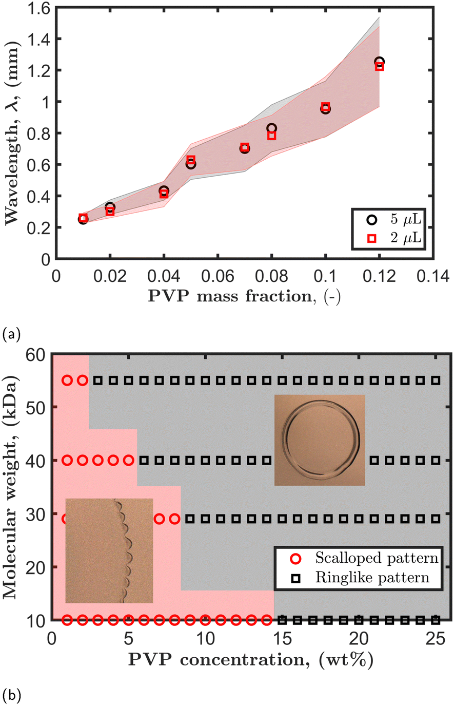 | ||
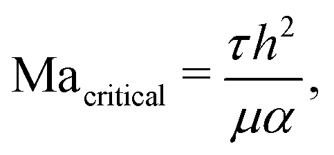
| Fig. 5 (a) Experimental measurement showing the effect of polymer mass fraction on the wavelength, conducted for two droplet volumes of 2 and 5 μL, with a polymer molecular weight of 10 kDa. The shaded area represents the experimental uncertainty. (b) Regime map illustrating the relationship between polymer molecular weight, concentration, and the resulting morphologies observed in PVP–ethanol droplets. | ||
A series of experiments was conducted to construct a regime map characterising the scalloped instability, by altering both the concentration and molecular weight of the polymer. The results, presented in Fig. 5b, demonstrate that the occurrence of the instability depends on the molecular weight of the polymer. The data show that at a lower molecular weight, e.g., 10 kDa, the instability is observed during the polymer droplet spreading, with a concentration reaching almost 15 wt%. In contrast, a higher molecular weight of 55 kDa only display the instability up to 2 wt%. The instability is suppressed when increasing the polymer concentration, likely due to viscosity hindering droplet spreading and promoting pinning of the droplet. The transition between the two distinct morphologies appears to coincide with the onset of polymer chain entanglement and the critical overlap concentration.
3.3 Physical mechanism of the scalloped instability
In Fig. 6a, the droplet radius and spreading time are normalised by the radius at which the droplet starts to exhibit the scalloped instability and its corresponding time. However, for concentrated droplets where the instability is not observed, the radius is normalised using the radius at which the ridge emerges. Fig. 6a reveals two distinct spreading dynamics associated with the droplets. Initially, droplets follow slow spreading dynamics characterised by a scaling relationship of R ∼ t1/10. Subsequently, the exponent shifts to a higher value, and the radius follows a scaling behaviour of R ∼ t1/4. The initial spreading dynamics align with Tanner's law.51,52 For dilute droplets with concentrations not exceeding 15 wt%, the duration of capillary spreading is observed to be short, lasting approximately 1 to 1.5 seconds. The later spreading dynamic is the period where spreading is fast and the droplet continues to spread until the surface is completely wetted or the droplet is pinned. The scaling relationship R ∼ t1/4 during this stage suggests that solutal Marangoni forces are dominating the outward flow rather than capillary forces.53–55 Therefore, the later dynamics are believed to be due to a solutal Marangoni flow, which might also be responsible for the formation of the edge instability at dilute concentrations. | ||
| Fig. 6 (a) Droplet radius development as a function of time plotted in logarithmic scale for 5 μL droplets containing different PVP concentrations deposited on a glass slide at 22 °C; the radius is normalised by the radius at the onset of the instability and its corresponding time. (b) A schematic shows the stages that a dilute PVP–ethanol droplet undergoes during spreading, causing the formation of the scalloped instability. (c) Height profiles for different PVP in ethanol droplet concentrations show the formation of a capillary ridge at the droplet periphery and an extended uniform thin film. | ||
The polymer used in these experiments, polyvinylpyrrolidone, is hygroscopic due to the existence of hydrophilic functional groups.44Fig. 2a demonstrates that PVP itself is not surface-active, indicating its inability to induce a Marangoni flow. However, it is plausible that the polymer contains trace amounts of water, leading to the generation of a Marangoni flow resulting from the differences in surface tension between ethanol and PVP containing trace water.
Fig. 6b is employed to propose a physical mechanism underlying the observed instability. The slow capillary spreading of the droplet, observed in Fig. 6a, facilitates the transport of polymer towards the droplet's periphery. This changes the local concentration within the droplet as more polymer and less solvent are present at the edge. PVP is hygroscopic and can absorb a significant amount of moisture, up to 40% of its weight depending on the relative humidity.56,57 The existence of water within the polymer matrix will increase the surface tension locally, and its value can be assumed to be similar to the surface tension of water ∼ 72 mN m−1. Therefore, a shear flow will be generated from the centre of the droplet to the edge due to the differences in the surface tension (Δγ = γpolymer − γethanol). This additional flow manifests as the second observed spreading dynamics in Fig. 6a, where the radius exhibits a scaling relationship of R ∼ t1/4.
Once Marangoni flow occurs, a capillary rim is formed at the edge of the droplet. This capillary ridge has the structure of the liquid cylinder extended across the contact line as seen in Fig. 4a. Notably, a uniform thin film is observed that extends behind the capillary rim prior to the formation of the edge pattern, as in Fig. 6c. Marangoni shear flows change the dynamics of the spreading as it pulls a thin film from the main droplet edge. The thickness of this uniform thin film remains approximately constant throughout the spreading process.39,58 The formation of this uniform thin film at early Marangoni flow is shown in Fig. S2 in the ESI,† and its thickness is reported in Fig. 6c.
The underlying cause of the observed edge instability, leading to the fragmentation of the fluid column at the droplet edge, has been proposed to be associated with a solutal Marangoni shear flow. When dealing with volatile components such as ethanol, it becomes crucial to differentiate between thermal and solutal effects. The evaporation of ethanol can induce evaporative cooling, causing variations in droplet temperature and subsequently giving rise to a thermal Marangoni flow. The extent to which these phenomena are influencing the flow can be estimated Smith and Davis59 computed a critical Marangoni number to measure the thermal effects of a horizontal layer in a system with large Prandtl numbers using
 | (2) |
The analogous compositional Marangoni number can be evaluated by replacing the thermal diffusivity with the molecular diffusivity in eqn (2). Using the values in Table 1, the compositional Marangoni number is evaluated
 | (3) |
| Parameter | Value |
|---|---|
| Shear stress (τ) | 1–2 Pa |
| Film thickness (h) | 1–10 μm |
| Viscosity (μ) | 1.8–4.3 mPa s |
| Molecular diffusivity (D) | 10−11–10−12 m2 s−1 |
| Thermal diffusivity (α) | 8.27 × 10⁻⁸ m2 s−1 |
Variation of surface tension with temperature  60 60 |
0.101 mN m−1 K−1 |
| Radial temperature gradient (ΔT)61 | 2–4 K |
| Drying time (tf) | 50 s |
| Maximum radius (Rmax) | 10–15 mm |
The thermal effects of an evaporating droplet can be also estimated using the Marangoni number, which is the ratio of a shear velocity induced by Marangoni stress to the mass loss velocity16
 | (4) |
 is the surface tension variation with temperature at the liquid–vapour surface, ΔT the horizontal temperature gradient, tf is the drying time, and Rmax the droplet maximum spreading radius. The Marangoni number is computed to be between 0.06 and 0.2, which is more than two orders of magnitude less than in systems where thermal Marangoni forces are significant.16 Therefore, in this case the effect of thermal Marangoni forces are assumed to be negligible.
3.4 Influence of surface wettability and evaporation rate
The appearance of the scalloped pattern is observed in the case of dilute PVP–ethanol polymer solution droplets that are deposited onto surfaces with high surface energy, such as a smooth glass slide or a silicon wafer. While pure ethanol exhibits complete wetting, when a hydrophobic substrate like polytetrafluoroethylene (PTFE) is utilised, ethanol only partially wets the surface, resulting in an apparent contact angle θapp = 31.5°. When dilute PVP solutions are employed, the droplets also exhibit partial wetting on a PTFE substrate, exhibiting finite contact angles that vary depending on the polymer concentration. In these droplets, the contact line becomes pinned, leading to the formation of a spherical cap droplet, as depicted in Fig. S3 and S4 in the ESI.† The contact line remains stable, and no discernible pattern is observed at the edge. This suggests that a combination of high surface wettability and outward Marangoni shear flow is likely responsible for this instability.The impact of ethanol evaporation from the droplet on the observed instability was explored by saturating the drying chamber with ethanol vapour. The objective of this approach was to determine whether the observed wavelength of the instability is controlled or modulated by the evaporation rate. Despite a considerable reduction of evaporation, the scalloped instability still manifests at the droplet edge, as seen in Fig. S5 in the ESI.† Furthermore, the wavelength of the instability exhibits comparable values between experiments conducted under ethanol vapour saturation and those conducted under normal atmospheric conditions where ethanol evaporation occurs unhindered (Table S1 in the ESI†). This observation suggests that even in scenarios characterised by reduced ethanol evaporation, the instability wavelength appears to remain unchanged.
Ethanol, characterised by high volatility, exhibits a vapour pressure (Pv) of 6.5 kPa at a temperature of 22 °C. Substituting ethanol with another volatile solvent, such as isopropanol (IPA), which possesses a lower Pv of 4.8 kPa, did not yield a significant impact on the observed instability, as depicted in Fig. 7. This can be attributed to the fact that both solvents demonstrate comparable surface tensions of approximately 22 mN m−1 at 22 °C,62 and the Marangoni forces at play in both systems are comparable despite differences in volatility.
 | ||
| Fig. 7 Variation of instability wavelength with PVP mass fraction for PVP–ethanol and PVP–isopropanol (IPA) systems. | ||
Furthermore, we modified the volatility of the solvent and the surface tension to further investigate the influence of evaporation and Marangoni forces on the observed instability. By selecting a solvent characterised by a low Pv, it becomes possible to examine the influence of surface tension gradients in the absence of significant solvent evaporation. DMF is characterised by its low volatility (with Pv ∼ 0.4 kPa) and higher surface tension (γ ∼ 36 mN m−1) compared to ethanol (γ ∼ 22 mN m−1). By employing a PVP–DMF mixture, evaporation from the droplet is rendered negligible, thereby resulting in a reduction of the surface tension gradient within the system and subsequently diminishing the magnitude of the Marangoni forces. The surface tension gradient in PVP–DMF is 15 times smaller than that in the PVP–ethanol system. While the droplet edge instability persists in the PVP–DMF system, the instability appears to have a fingerlike shape, as seen in Fig. 8 and Movie S2 (ESI†). Upon depositing the droplet, multiple regions of the droplet break the symmetry and start to exhibit an edge instability. The fingerlike shape can be attributed to the solvents’ surface tension and wetting properties.38 While the presence of evaporation is important to initiate a solutal Marangoni flow, the instability wavelength appears to remain unchanged even when lower vapour pressure solvents are used.
 | ||
| Fig. 8 Sequential top-view images capturing the spreading behaviour of a 5 μL droplet with 5 wt% PVP in N,N-dimethylformamide, a non-volatile solvent, on a glass slide at 22 °C. The images highlight the observed instability at the droplet edge. | ||
3.5 Suppressing the scalloped instability
It has been shown that the presence of a scalloped instability at the droplet edge arises from the additional shear flow resulting from differences in surface tension within the droplet. The experimental materials, namely PVP and ethanol, were utilised in their commercially obtained forms, and trace water can easily be dissolved from the atmosphere into both.Various methods exist for eliminating trace water, with molecular sieves of type 3 Å being a commonly employed approach. The following experimental procedure was employed to ensure the removal of water from PVP solutions: solid PVP was initially subjected to oven drying at a temperature of 70 °C for 1 hour, ensuring the elimination of any residual water. Subsequently, the dried PVP was stored in a vacuum desiccator. The polymer solution was subsequently prepared by combining the desiccated PVP with ethanol, after which molecular sieves were washed, regenerated, and added to the different polymer mixtures. The resulting solutions were then sealed within vials using screw caps equipped with PTFE liners, and left within a desiccator for a period of one day.
Fig. 9 illustrates the successful suppression of the instability. Quantifying the amount of water required to initiate the instability within the mixture is challenging; however, the complete removal of water is shown to suppress the instability.
 | ||
| Fig. 9 Top-view sequence of images depicting the suppression of the scalloped instability in a 5 μL droplet comprising 5 wt% PVP in ethanol on a glass substrate at 22 °C. | ||
The droplet in Fig. 9 exhibits a reduced spreading rate and coverage area compared to a droplet where trace water removal was not conducted, as shown in Fig. 3. Specifically, the final radius of the 5 wt% droplet in Fig. 9 measures 5 mm, in contrast to the 10 mm radius observed in Fig. 3. These observations provide further evidence supporting that a solutal Marangoni flow serves as the underlying physical mechanism driving this particular instability.
3.6 Instability theoretical approach
The scalloped instability, which is driven by solutal Marangoni flow, exhibits analogous characteristics to contact line instabilities in thin films driven by other forces, such as gravity and thermal Marangoni flow.29,63,64 The mathematical derivation is shown in depth in the ESI.† In the main article text, we summarise the method and quote the result.The starting point is the Navier–Stokes equations. The lubrication approximation is assumed valid due to the small aspect ratio of the droplet. A steady-state condition is assumed for the droplet, whereby the flow is governed by a constant shear solutal Marangoni flow from the centre of the droplet to the extended film near the contact line. This flow regime ensures uniform film thickness near the contact line, as has been experimentally observed. Furthermore, experimental observations indicate that evaporation from the thin film near the contact line is negligible, owing to the continuous flow from the parent droplet.39,58 The free interface near the contact line is derived through the use of a classical long-wave evolution equation, based on the premise of a constant solutal Marangoni flow, which is in accordance with previous studies.27,36,64 In addition, a linear stability analysis is conducted on the steady state solution, revealing that the most unstable wavelength is determined to be λ = 17h0(γ/3μu0)1/3 (refer to the ESI†). Here, μ is the initial solution viscosity, γ is the initial solution surface tension, h0 is the uniform film thickness behind the capillary ridge, and u0 is the droplet Marangoni velocity, which are presented in Table 2. Notably, this wavelength is similar to previous studies that have considered a constant thermal Marangoni flow in spreading thin films on vertical substrates.36,63,64
| Concentration (wt%) | Viscosity (mPa s) | Experimental velocity (μm s−1) | Film height (μm) | Predicted velocity (μm s−1) | Predicted wavelength (μm) |
|---|---|---|---|---|---|
| 1 | 1.15 | 2597 ± 240 | 1.4 ± 0.2 | 1883 | 356 |
| 5 | 1.67 | 1753 ± 220 | 3 ± 0.1 | 1631 | 709 |
| 7 | 1.96 | 1555 ± 160 | 3.8 ± 0.3 | 1540 | 868 |
| 10 | 2.71 | 1322 ± 105 | 5.2 ± 0.2 | 1358 | 1112 |
| 12 | 3.26 | 1103 ± 80 | 6.4 ± 0.5 | 1270 | 1316 |
The predicted Marangoni velocity is derived at steady state, using a solvent concentration equation to be  . Here, C is the concentration, subscript A refers to ethanol, and B is the polymer containing trace water. E is the evaporation rate, which for ethanol was measured experimentally from mass loss experiments at 22 °C, as E = 1.6 × 10⁻⁷ m s−1. Ethanol surface tension is 22 mN m−1 and PVP containing trace water is 72 mN m−1. The predicted velocity is calculated and tabulated along with the predicted wavelength in Table 2. Fig. 10 depicts the good agreement between the measured and predicted wavelength of the observed instability in dilute PVP–ethanol droplets.
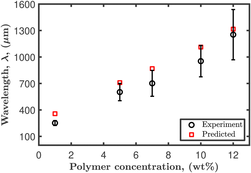 | ||
| Fig. 10 Predicted and experimental wavelength of the scalloped instability for different PVP–ethanol concentrations. | ||
4 Conclusions
This study investigates the spreading and evaporation dynamics of polymer droplets comprising a hygroscopic polymer, PVP, dissolved in ethanol on a high-energy surface. The analysis of the final morphology of these polymer droplets reveals two distinct edge patterns: a ringlike and a scalloped pattern. The transition between these two patterns coincides with the onset of the critical overlap concentration. Droplets with low polymer concentrations fully wet the substrate and exhibit a scalloped instability at the droplet edge. The spreading dynamics of such droplets exhibit two regimes: a slow spreading regime driven by droplet curvature and a fast spreading regime driven by concentration-dependent surface tension gradients, specifically solutal Marangoni flow. The presence of a surface tension gradient arises from the hygroscopic nature of the polymer, which allows for the absorption of small amounts of water. The onset of Marangoni flow is observed during the initial spreading regime, where the polymer is transported to the droplet edge, creating a concentration gradient within the droplet. This leads to the generation of an interfacial flow and the formation of a capillary ridge at the droplet edge. The front ridge grows due to fluid accumulation and becomes unstable, eventually breaking into smaller droplets, forming the scalloped instability pattern.Thermal effects resulting from droplet evaporation were estimated and found to be negligible compared to concentration effects. The impact of evaporation on the observed instability is found to be small. This observation is further supported by comparing it to another system, PVP in DMF, where DMF is non-volatile compared to ethanol. In this alternative system, the edge instability is still observed with fingerlike shapes. An investigation into the influence of the substrate reveals that this instability exclusively occurs on high-energy surfaces, where the droplets exhibit a low apparent contact angle. The edge instability observed in PVP in ethanol droplets can be controlled and suppressed by removing trace amounts of water from the solution prior to droplet deposition, thereby eliminating any Marangoni shear flow. The long-wave evolution equation is employed, assuming a constant Marangoni shear flow, to predict the most unstable wavelength. The results indicate good agreement between the predicted and experimental wavelengths.
PVP–ethanol droplets investigated in this study, driven by Marangoni flow, have the potential to cover a large surface area. This could be advantageous for producing thin coatings, typically less than 10 μm thick, which could be used for coating polymer solar cells without significant material wastage.
Conflicts of interest
There are no conflicts to declare.Acknowledgements
This work has been funded by the Engineering and Physical Sciences Research Council (EPSRC), and CASE studentship funding from Unilever UK.References
- A. Ressine, S. Ekström, G. Marko-Varga and T. Laurell, Anal. Chem., 2003, 75, 6968–6974 CrossRef CAS PubMed.
- M. Naqshbandi, J. Canning, B. C. Gibson, M. M. Nash and M. J. Crossley, Nat. Commun., 2012, 3, 1188–1195 CrossRef PubMed.
- F. Zhang, C. Tuck, R. Hague, Y. He, E. Saleh, Y. Li, C. Sturgess and R. Wildman, J. Appl. Polym. Sci., 2016, 133, 43361 CrossRef.
- H. Li, I. Travlos, L. Qi, P. Kanatas and P. Wang, J. Agron., 2019, 9, 547–559 CAS.
- S. Basi, M. Hunsche and G. Noga, Weed Res., 2013, 53, 1–11 CrossRef CAS.
- W. Bou Zeid, J. Vicente and D. Brutin, Colloids Surf., A, 2013, 432, 139–146 CrossRef CAS.
- R. D. Deegan, O. Bakajin, T. F. Dupont, G. Huber, S. R. Nagel and T. A. Witten, Phys. Rev. E, 2000, 62, 756–765 CrossRef CAS PubMed.
- A. F. Routh, Rep. Prog. Phys., 2013, 76, 046603 CrossRef PubMed.
- D. Zang, S. Tarafdar, Y. Tarasevich, M. Dutta Choudhury and T. Dutta, Phys. Rep., 2019, 804, 1–56 CrossRef CAS.
- B. J. Fischer, Langmuir, 2002, 18, 60–67 CrossRef CAS.
- C. N. Kaplan and L. Mahadevan, J. Fluid Mech., 2015, 781, R2 CrossRef.
- B. M. Weon and J. H. Je, Phys. Rev. E, 2010, 82, 015305 CrossRef PubMed.
- R. Bhardwaj, X. Fang, P. Somasundaran and D. Attinger, Langmuir, 2010, 26, 7833–7842 CrossRef CAS PubMed.
- M. B. Ji, Y. Changhyun and Y. R. Joo, Curr. Appl. Phys., 2018, 18, 477–483 CrossRef.
- H. B. Eral, D. M. Augustine, M. H. G. Duits and F. Mugele, Soft Matter, 2011, 7, 4954–4958 RSC.
- R. G. Larson, AIChE J., 2014, 60, 1538–1571 CrossRef CAS.
- H. Gelderblom, C. Diddens and A. Marin, Soft Matter, 2022, 18, 8535–8553 RSC.
- L. Pauchard, J. Hulin and C. Allain, Europhys. News, 2005, 36, 9–10 CrossRef.
- L. Pauchard and C. Allain, C. R. Phys., 2003, 4, 231–239 CrossRef CAS.
- N. Tsapis, E. R. Dufresne, S. S. Sinha, C. S. Riera, J. W. Hutchinson, L. Mahadevan and D. A. Weitz, Phys. Rev. Lett., 2005, 94, 756–765 CrossRef PubMed.
- S. Basu, L. Bansal and A. Miglani, Soft Matter, 2016, 12, 4896–4902 RSC.
- L. Pauchard and C. Allain, Europhys. Lett., 2003, 62, 897–903 CrossRef CAS.
- T. Kajiya and M. Doi, J. Soc. Rheol., 2011, 39, 17–28 CrossRef CAS.
- A. D. Eales, A. F. Routh, N. Dartnell and G. Simon, AIChE J., 2015, 61, 1759–1767 CrossRef CAS.
- J. M. Davis, B. J. Fischer and S. M. Troian, Interfacial Fluid Dynamics and Transport Processes, Springer, Berlin, Heidelberg, 2003 Search PubMed.
- R. V. Craster and O. K. Matar, Rev. Mod. Phys., 2009, 81, 1131–1198 CrossRef CAS.
- S. M. Troian, J. F. Joanny and S. A. Safran, Europhys. Lett., 1989, 10, 25–30 CrossRef.
- M. A. Spaid and G. M. Homsy, Phys. Fluids, 1996, 8, 460–478 CrossRef CAS.
- L. Kondic, SIAM Rev., 2003, 45, 95–115 CrossRef.
- F. Melo, J. F. Joanny and S. Fauve, Phys. Rev. Lett., 1989, 63, 1958–1961 CrossRef CAS PubMed.
- S. K. Wilson, R. Hunt and B. R. Duffy, J. Fluid Mech., 2000, 413, 65–88 CrossRef CAS.
- A. Arora and P. Doshi, Phys. Fluids, 2016, 28, 013102 CrossRef.
- A. M. Cazabat, F. Heslot, S. M. Troian and P. Carles, Nature, 1990, 346, 824–826 CrossRef CAS.
- S. M. Troian, E. Herbolzheimer and S. A. Safran, Phys. Rev. Lett., 1990, 65, 333–336 CrossRef CAS PubMed.
- O. E. Jensen and J. B. Grotberg, Phys. Fluids A: Fluid Dyn., 1993, 5, 58–68 CrossRef CAS.
- D. E. Kataoka and S. M. Troian, J. Colloid Interface Sci., 1997, 192, 350–362 CrossRef CAS PubMed.
- Y. Gotkis, I. Ivanov, N. Murisic and L. Kondic, Phys. Rev. Lett., 2006, 97, 186101 CrossRef CAS PubMed.
- A. P. Mouat, C. E. Wood, J. E. Pye and J. C. Burton, Phys. Rev. Lett., 2020, 124, 64502 CrossRef CAS PubMed.
- R. Vuilleumier, V. Ego, L. Neltner and A. M. Cazabat, Langmuir, 1995, 11, 4117–4121 CrossRef CAS.
- J. B. Fournier and A. M. Cazabat, Europhys. Lett., 1992, 20, 517–522 CrossRef CAS.
- D. C. Venerus and D. Nieto Simavilla, Sci. Rep., 2015, 5, 16162 CrossRef CAS PubMed.
- X. Ma, M. Zhong, Y. He, Z. Liu and Z. Li, Phys. Fluids, 2020, 32, 112112 CrossRef CAS.
- C. Poulard and P. Damman, Europhys. Lett., 2007, 80, 64001 CrossRef.
- F. Haaf, A. Sanner and F. Straub, Polym. J., 1985, 17, 143–152 CrossRef CAS.
- M. Teodorescu and M. Bercea, Polym.-Plast. Technol. Mater., 2015, 54, 923–943 CrossRef CAS.
- M. Kurakula and G. S. Rao, J. Drug Delivery Sci. Technol., 2020, 60, 102046 CrossRef CAS PubMed.
- E. Huang, A. Skoufis, T. Denning, J. Qi, R. R. Dagastine, R. F. Tabor and J. D. Berry, J. Open Source Softw., 2021, 6, 2604 CrossRef.
- I. Teraoka, Polymer Solutions: An Introduction to Physical Properties, John Wiley & Sons, Inc., 2002 Search PubMed.
- R. D. Deegan, O. Bakajin, T. F. Dupont, G. Huber, S. R. Nagel and T. A. Witten, Nature, 1997, 389, 827–829 CrossRef CAS.
- S. Semenov, V. M. Starov, M. G. Velarde and R. G. Rubio, Eur. Phys. J., 2011, 197, 265–278 CAS.
- L. H. Tanner, J. Phys. D: Appl. Phys., 1979, 12, 1473–1484 CrossRef CAS.
- A. M. Cazabat and A. Stuart, J. Phys. Chem., 1986, 90, 5845–5849 CrossRef CAS.
- A. Marmur, Adv. Colloid Interface Sci., 1983, 19, 75–102 CrossRef CAS.
- D. Pesach and A. Marmur, Langmuir, 1987, 3, 519–524 CrossRef CAS.
- M. D. Lelah and A. Marmur, J. Colloid and Interface Sci., 1981, 82, 518–525 CrossRef CAS.
- S. Fitzpatrick, J. F. McCabe, C. R. Petts and S. W. Booth, Int. J. Pharm., 2002, 246, 143–151 CrossRef CAS PubMed.
- Y. K. Mahadevappa, A. K. Arjumand and R. K. Ravindra, Natural and Synthetic Biomedical Polymers, Elsevier, Oxford, 2014 Search PubMed.
- A. de Ryck, J. Colloid Interface Sci., 1999, 209, 10–15 CrossRef CAS PubMed.
- M. K. Smith and S. H. Davis, J. Fluid Mech., 1983, 132, 119–144 CrossRef CAS.
- F. A. Gonalves, A. R. Trindade, C. S. Costa, J. C. Bernardo, I. Johnson, I. M. Fonseca and A. G. Ferreira, J. Chem. Thermodyn., 2010, 42, 1039–1049 CrossRef.
- X. Zhong and F. Duan, Sci. Rep., 2017, 7, 16219–16228 CrossRef PubMed.
- G. Vazquez, E. Alvarez and J. M. Navaza, J. Chem. Eng. Data, 1995, 40, 611–614 CrossRef CAS.
- D. E. Kataoka and S. M. Troian, Nature, 1999, 402, 794–797 CrossRef CAS.
- J. M. Davis and S. M. Troian, Phys. Rev. E, 2003, 67, 016308 CrossRef PubMed.
Footnote |
| † Electronic supplementary information (ESI) available. See DOI: https://doi.org/10.1039/d3sm00968h |
| This journal is © The Royal Society of Chemistry 2023 |