
 Open Access Article
 This Open Access Article is licensed under a
 Creative Commons Attribution 3.0 Unported Licence
Coarsening transitions of wet liquid foams under microgravity conditions
Marina
Pasquet
 a,
Nicolo
Galvani
bd,
Alice
Requier
a,
Sylvie
Cohen-Addad
bc,
Reinhard
Höhler
bc,
Olivier
Pitois
d,
Emmanuelle
Rio
a,
Anniina
Salonen
a and
Dominique
Langevin
*a
a,
Nicolo
Galvani
bd,
Alice
Requier
a,
Sylvie
Cohen-Addad
bc,
Reinhard
Höhler
bc,
Olivier
Pitois
d,
Emmanuelle
Rio
a,
Anniina
Salonen
a and
Dominique
Langevin
*a
aUniversité Paris-Saclay, CNRS, Laboratoire de Physique des Solides, 91405, Orsay, France. E-mail: dominique.langevin@universite-paris-saclay.fr
bSorbonne Université, CNRS-UMR 7588, Institut des NanoSciences de Paris, 4 place Jussieu, 75005 Paris, France
cUniversité Gustave Eiffel, 5 Bd Descartes, Champs-sur-Marne, F-77454 Marne-la-Vallée cedex 2, France
dUniversité Gustave Eiffel, ENPC, CNRS, Laboratoire Navier, 5 Bd Descartes, Champs-sur-Marne, F-77454 Marne-la-Vallée cedex 2, France
First published on 26th July 2023
Abstract
We report foam coarsening studies which were performed in the International Space Station (ISS) to suppress drainage due to gravity. Foams and bubbly liquids with controlled liquid fractions ϕ between 15 and 50% were investigated to study the transition between bubble growth laws previously reported near the dry limit ϕ → 0 and the dilute limit ϕ → 1 (Ostwald ripening). We determined the coarsening rates for the driest foams and the bubbly liquids, they are in close agreement with theoretical predictions. We observe a sharp cross-over between the respective laws at a critical value ϕ*. At liquid fractions beyond this transition, neighboring bubbles are no longer all in contact, like at a jamming transition. Remarkably ϕ* is significantly larger than the random close packing volume fraction of the bubbles ϕrcp which was determined independently. We attribute the differences between ϕ* and ϕrcp to a weakly adhesive bubble interaction that we have studied in complementary ground-based experiments.
1 Introduction
Foams are concentrated dispersions of gas bubbles in a liquid or solid matrix.1,2 Solid foams, obtained by solidifying liquid foams, are light-weight materials used for thermal or acoustic insulation or as construction materials. Liquid foams also have many applications, such as detergency, flotation, and oil recovery. Even when they are stabilized by surface-active agents adsorbed to the gas liquid interfaces, such as surfactants, liquid foams are generally short-lived. Understanding and controlling foam stability is therefore mandatory for applications.Foams are destabilized by three main processes: gravity induced drainage, coarsening of the structure due to the transfer of gas between bubbles driven by Laplace pressure differences, and bubble coalescence, due to the rupture of the liquid films between bubbles. These three processes are coupled in a complex manner.2 For instance, coarsening and coalescence become faster when the liquid content of the foam decreases due to drainage. To study coarsening and coalescence under well controlled conditions, drainage needs to be suppressed. This can be achieved by rotating the sample in a clinostat, but the method is usually limited to foams with small liquid volume fractions, up to 15%. A reliable way to study such foams is to perform experiments in microgravity. Even in the absence of drainage, it is still necessary to suppress one of the two remaining destabilisation processes, in order to study the other one accurately. To focus on coarsening, one can use efficient surfactants in appropriate concentrations to prevent coalescence.2 In this paper, we present a study of foam coarsening performed in the International Space Station (ISS) where gravity drainage is absent, so that we could study the coarsening of foams containing a wide range of liquid volume fractions which are homogeneous throughout the sample and stable against coalescence.
In foams where the liquid volume fraction is small, called dry foams, the bubbles are squeezed against each other so strongly that their shape is polyhedral. They are separated by liquid films, connected three by three through channels called Plateau borders. With increasing liquid fraction ϕ, the bubble shapes become more and more spherical. Beyond a critical liquid fraction ϕ*, neighboring bubbles are no longer all in contact; such dispersions are called bubbly liquids. This jamming transition has a strong impact on the mechanical properties of foams and similar materials; it induces a transition from solid-like elastic to liquid-like viscous behavior.2 For a random assembly of monodisperse hard spheres, ϕ* is known to be about 36% and corresponds to the random close packing fraction ϕrcp of monodisperse spheres. This value decreases with increasing polydispersity of the spheres.3 Jamming may be defined either in terms of the appearance of bubble contact films or of the onset of solid-like mechanical behavior. In adhesive systems, these features are not necessarily correlated, in contrast to non-adhesive systems.4 In our work, we will use a definition based only on the existence of contact films, evidenced by the coarsening dynamics.
The aim of our study is to investigate how coarsening is affected by the structural change near the jamming transition. In dry foams, gas is transferred among neighboring bubbles mainly by diffusion through the contact films, and there is a strong link between the topology of the packing and the concentration gradients driving gas exchange with neighbors. In the limit of large liquid fractions, bubbles form a dilute dispersion and exchange gas with the surrounding bulk liquid, which acts like a reservoir of dissolved gas. This process is known as Ostwald ripening. In both cases, the bubble growth is governed by asymptotic power laws, but their exponents are different. The transition between these two limiting cases and its relation with the structural change at the jamming transition are not yet well understood and the experiments with foams and emulsions do not yet provide a clear global picture of coarsening. Note that grain growth in solid dispersions is similar to foam coarsening, but it is more complex, due to the anisotropy of the crystal lattice.5
We have therefore performed coarsening experiments using samples with liquid fractions in the range 15% ≤ ϕ ≤ 50%, covering both sides of the jamming transition. Fig. 1 illustrates the coarsening of a foam with a liquid fraction of 25% obtained in our experiments. The behavior of these dispersions not only depends on liquid fraction, it can also be modified by attractive interactions.6,7 Attraction can enhance contact forces and film areas at liquid fractions above ϕrcp, and give rise to soft solid-like behavior for ϕ > ϕrcp where bubbles form gel-like networks. The mechanical behavior of gelled droplet dispersions8,9 has been investigated recently, but to our knowledge coarsening studies of gelled bubble or droplet suspensions have not been reported. We worked here with weakly attractive bubbles. We have determined the contact angle that characterizes this attraction and discuss its relation to the observed coarsening behavior, which differs from predictions for repulsive bubble packings.
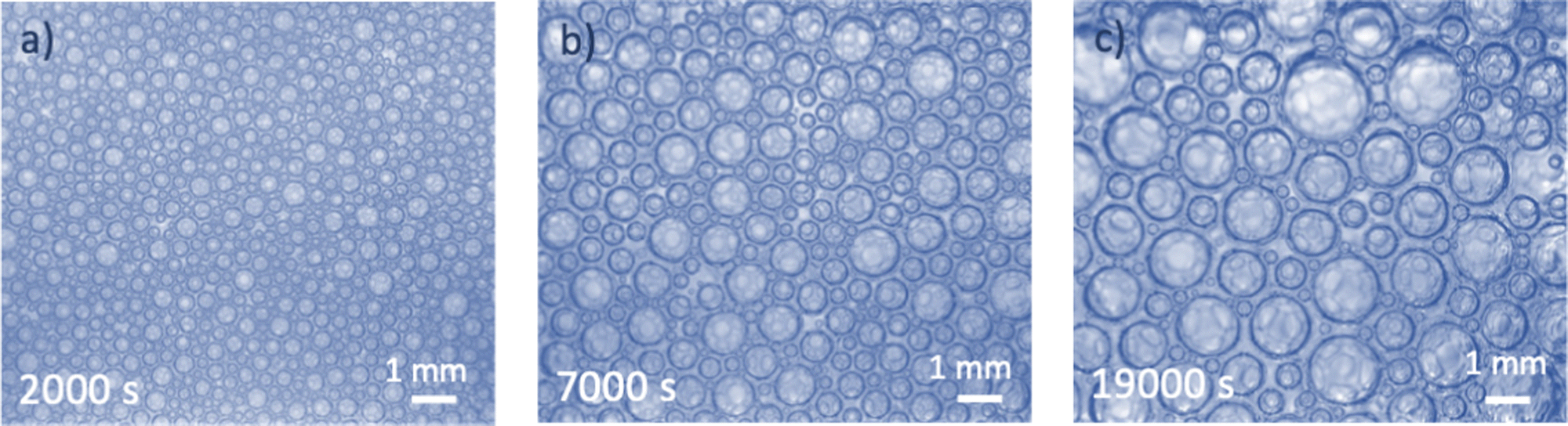 | ||
| Fig. 1 Foam coarsening in microgravity onboard the ISS. The liquid fraction is ϕ = 25%. The times indicate the duration elapsed since the end of the sample foaming. | ||
Theoretical analyses and simulations of coarsening in foams,10 emulsions11 and annealed metals5 predict, in agreement with experimental results, that after a transient regime, the distribution of bubble, droplet or grain radii, normalized by their average value, becomes invariant with time. In this so-called scaling state, the particle growth is statistically self-similar.
Growth models have been established for either small or large continuous phase volume fractions. In these models, the predicted average radius can be defined with different weightings, but in the self-similar regime the different average radii are proportional to each other. In the limit of small liquid fractions ϕ → 0 (dry foam limit), the average radius 〈R〉 is predicted to increase with time t following a parabolic law:
| 〈R(t)〉2 = 〈Ro〉2 + Ωp(t − to) | (1) |
The radius R(t) is an equivalent radius, proportional to the square root of the area of the bubbles which are not spherical. In the opposite limit where ϕ → 1 (dilute bubbly liquid), the number average radius is predicted to increase with time as:
| 〈R(t)〉3 = 〈Ro〉3 + Ωc(t − to) | (2) |
The growth exponents do not depend on the choice of a specific definition of average radius, but the growth rates Ωp and Ωr will depend it.
The limit of small liquid fraction was first analyzed by Neuman,12 Wagner13 and Mullins,14 and confirmed by experiments with dry foams.15,16 The opposite limit, called Ostwald ripening, was studied by Lifshitz, Slyozov17 and Wagner13 (LSW), and confirmed by experiments with alloys5 and dilute emulsions.11 In both equations 〈Ro〉 is the average radius at a reference time to in the scaling state. With increasing time, eqn (1) and (2) respectively converge to power laws: 〈R〉 ∼t1/2 in dry foams and 〈R〉 ∼t1/3 in dilute bubble dispersions.
The modification of the exponent as a function of liquid fraction is related to the mechanism of diffusive gas transfer between bubbles. In dry foams, it occurs mostly through the thin films separating a bubble from its neighbors, and whose thickness, of the order of tens of nanometers, varies only weakly with bubble size. The flow is driven by the difference between the Laplace pressures in the bubble and in its neighbors. In bubbly liquids, bubbles exchange gas with the surrounding liquid, whose gas concentration is set by the average bubble pressure in the neighbors. In this case, the dissolved gas concentration decreases with the distance from the bubble surface over a range of the order of the bubble radius. The gas transfer in foams and bubbly liquids is thus set by two different length scales, in the first case the film thickness which is practically constant, and in the second case the bubble radius which evolves with time.14 Similar remarks apply to coarsening of emulsions.
The growth laws are thus well understood theoretically in the limiting cases of small and large liquid fractions but the knowledge at intermediate liquid fractions is still lacking.
In the following, after describing the experimental details, we will present our results on bubble growth laws and analyze the different regimes we have evidenced.
2 Materials and methods
The experiments are performed aboard the International Space Station using the experiment container described in ref. 18. The residual gravity acceleration fluctuations on board the ISS are reported to be on the order of or less than 10−6 g, for frequencies below 0.01 Hz.19 Each foam sample is placed in a hermetically closed transparent cell, containing the required volumes of foaming liquid and air to obtain a given liquid fraction ϕ. The foam sample is generated in situ using the back and forth actuation of the magnetic piston in the cell. The range of investigated liquid fractions lies between 15% and 50%. The foams are made using aqueous solutions of the surfactant Tetradecyl-Trimethyl-Ammonium Bromide TTAB (purchased from Sigma-Aldrich, purity ≥99%) in ultrapure water. The TTAB concentration is c = 5 g L−1, about 4 times larger than the critical micellar concentration (cmc = 1.2 g L−1) so that the bubbles do not coalesce. The surface tension γ of the TTAB solution measured at room temperature is: γ = 37.1 mN m−1.The experiment container is equipped with a camera that records images of the bubbles at the surface of the cell and with a probe based on multiple light scattering, Diffuse Transmission Spectroscopy (DTS) as described in ref. 18. The images are analyzed manually as described in ref. 20. For each liquid fraction, we have measured the bubble size distributions as a function of foam age t, i.e. time elapsed since the end of the foaming, and identified the scaling state.21 Using these distributions, we calculated the different averages  . The number average radius is R10 and the mean Sauter radius R32.
Diffuse Transmission Spectroscopy consists in measuring the light intensity diffusely transmitted through the sample. The average bubble radius in the bulk of foam is then deduced from the measured transmission coefficient for the specific geometry of the ISS set-up, as detailed in ref. 20. The results showed that, for the same foam samples as studied here, the evolution of the average bubble size observed at the surface and in the bulk are the same within experimental error.20 We focus in this paper on the bubble growth laws R32(t) and will use the data from this earlier publication.
Ground experiments were also performed to characterize the adhesion between bubbles. Monodisperse bubbles with the same TTAB concentration as in the coarsening experiments were formed in a microfluidic T junction generator. The glassware, Teflon tubing and the microfluidic device were carefully cleaned before use. The gas was air to which fluorinated vapour (perfluorohexane C6F14) was added in order to stop ripening and to prevent the bubbles from becoming polydisperse. Dilute bubble dispersions were injected into a hermetically closed observation cell, filled with the TTAB solution and covered by a glass plate without any air pocket. The contact angles were measured using image analysis and the method described in ref. 22.
3 Experimental results
3.1 Bubble growth laws
Fig. 2 shows the evolution of the Sauter mean bubble radius with foam age, deduced from image analysis and DTS light scattering data, for each investigated liquid fraction. The bubble growth with age can be fitted in the scaling state by power laws: R32 ∼ tα, with α ≈ 1/2 for ϕ ≤ 37.5% and α ≈ 1/3 for ϕ ≥ 40% (see Table 1). The cross over between these two regimes occurs near a liquid fraction ϕ* ≈ 39% and is rapid as illustrated in Fig. 8 of the Appendix.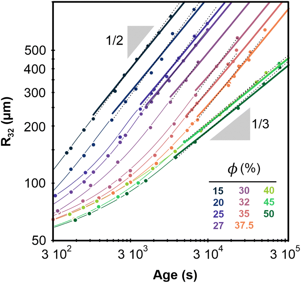 | ||
| Fig. 2 Average bubble Sauter radius versus foam age for the different liquid fractions. The radii are measured with an accuracy of 15 μm. Dotted lines represent power laws R32 ∝ tα obtained by fits within the scaling state. Corresponding prefactors and exponents α are reported in Table 1. The thick continuous lines represent growth laws within the scaling state, obtained by fitting a parabolic law to the data for ϕ ≤ 37.5% and a cubic law to the data for ϕ ≥ 40%, as explained in the text. The fixed parameters Ro = 60 μm, and corresponding to are indicated in Table 1 for ϕ values increasing from 15% to 50% as labelled in the graph. The thin curves are extrapolations of the thick ones using eqn (1) and (2). | ||
| ϕ(%) | 15 | 20 | 25 | 27 | 30 | 32 | 35 | 37.5 | 40 | 45 | 50 |
| R 32/R21 | 1.3 | 1.3 | 1.3 | 1.3 | 1.3 | 1.2 | 1.2 | 1.2 | 1.1 | 1.1 | 1.1 |
| R 32/R10 | 2.0 | 2.2 | 2.0 | 2.0 | 1.9 | 1.7 | 1.6 | 1.6 | 1.2 | 1.2 | 1.1 |
| Polydispersity | 0.38 | 0.41 | 0.37 | 0.37 | 0.34 | 0.27 | 0.25 | 0.24 | 0.09 | 0.09 | 0.06 |
| t o (s) | 87 | 78 | 68 | 68 | 68 | 68 | 68 | 284 | 243 | 243 | 214 |
| Fitted exponent α | 0.55 | 0.55 | 0.55 | 0.52 | 0.59 | 0.55 | 0.52 | 0.51 | 0.36 | 0.35 | 0.35 |
| Prefactor (μm s−α) | 5.00 | 3.48 | 2.60 | 3.17 | 1.20 | 1.18 | 1.51 | 1.36 | 4.90 | 5.79 | 4.90 |
| Exponent | 1/2 | 1/2 | 1/2 | 1/2 | 1/2 | 1/2 | 1/2 | 1/2 | 1/3 | 1/3 | 1/3 |
| Ωp,R32 (μm2 s−1) | 55 | 31 | 16 | 13 | 7.9 | 4.3 | 3.2 | 2.1 | — | — | — |
| Ωc,R32 (μm3 s−1) | — | — | — | — | — | — | — | — | 288 | 281 | 219 |
Our study of the bubble size distribution of the same coarsening foams21 shows that due to their polydispersity, the volume fraction that corresponds to the random close packing is: ϕrcp ≈ 31%. Therefore, at ϕ > 31% one would expect gas transfer to occur no longer through contact films but through bulk liquid, and the coarsening exponent should then be 1/3, in contradiction with our observations showing such an exponent only for ϕ > ϕ* > ϕrcp. Since the coarsening exponent 1/2 is a signature of a gas transfer mechanism predominantly through the contact films between the bubbles, our results suggest that the films persist far above ϕrcp, and up to ϕ*. We attribute this effect to adhesive bubbles interactions that promote contact films as shown by observations reported in the Section 3.2.
By reminiscence of the dry foam and the dilute bubble dispersion respectively, we name the regimes we observed:
(i) The adhesive foam regime, for ϕ < ϕ*.
(ii) The bubbly liquid regime, for ϕ > ϕ*.
In the adhesive foam regime, we expect the growth rate to be described by eqn (1). We determine the coarsening rate Ωp for each ϕ, by fitting to the data the growth law: R322(t) = Ro2 + Ωp,R32![[thin space (1/6-em)]](https://www.rsc.org/images/entities/char_2009.gif) (t − to). Since the foaming process yields samples whose initial bubble radius R32 is close to 60 μm, we choose for all ϕ a reference radius Ro = 60 μm and the corresponding reference time to. From the bubble size distribution analysis,21 we obtain the time (and bubble size) where the foam has reached the scaling state. For all investigated liquid fractions, this happens for R32 ⪆ 250 μm. Thus we fit the parameter Ωp,R32 in the corresponding range of times in the scaling state. We do a similar analysis to determine the coarsening rate Ωc,R32 in the bubbly liquid regime with the growth law: R323(t) = Ro3 + Ωc,R32(t − to). As can be seen in Fig. 2, all of these growth laws fit well to the data in each regime. The values of the coarsening rates are reported in Table 1. We observe that coarsening slows down as the liquid fraction increases in each regime. In Sections 5.1 and 5.2, we discuss quantitatively the dependency of Ωp,R32 and Ωc,R32 with liquid fraction.
(t − to). Since the foaming process yields samples whose initial bubble radius R32 is close to 60 μm, we choose for all ϕ a reference radius Ro = 60 μm and the corresponding reference time to. From the bubble size distribution analysis,21 we obtain the time (and bubble size) where the foam has reached the scaling state. For all investigated liquid fractions, this happens for R32 ⪆ 250 μm. Thus we fit the parameter Ωp,R32 in the corresponding range of times in the scaling state. We do a similar analysis to determine the coarsening rate Ωc,R32 in the bubbly liquid regime with the growth law: R323(t) = Ro3 + Ωc,R32(t − to). As can be seen in Fig. 2, all of these growth laws fit well to the data in each regime. The values of the coarsening rates are reported in Table 1. We observe that coarsening slows down as the liquid fraction increases in each regime. In Sections 5.1 and 5.2, we discuss quantitatively the dependency of Ωp,R32 and Ωc,R32 with liquid fraction.
3.2 Attraction between bubbles
In some microgravity experiments with large liquid fractions, we have observed regions with very few bubbles, organized in clusters. An example is illustrated in Fig. 3a. Such a heterogeneous distribution of bubbles and the formation of aggregated clusters suggest the presence of an attractive bubble interaction. To verify the presence of attraction between bubbles dispersed in a TTAB solution, additional experiments were performed on ground. Dilute dispersions of bubbles were confined under a transparent horizontal plate as described in Section 2. The image shown in Fig. 3b confirms the spontaneous formation of clusters, indicating significant bubble adhesion in TTAB solutions. When the cell containing the bubble dispersion is tilted slightly, the bubbles migrate slowly along the transparent top plate, driven by buoyancy. This observation indicates that there are no pinning effects due to residual surface roughness of the top plate. The adhesive force must be very small because the bubbles are easily dispersed when the liquid in the cell is agitated. We observed similar adhesion with a smaller TTAB concentration, below the cmc (1 g L−1), arguing against an effect due to micellar depletion which would disappear in this case. Similar clustering was also obtained at a larger TTAB concentration (20 g L−1). These experiments were repeated with highly purified TTAB and the same results were obtained, arguing against impurity related artifacts.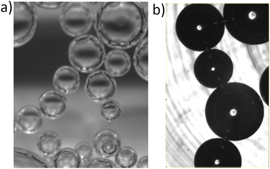 | ||
| Fig. 3 (a) Bubble clusters surrounded by foaming liquid, spontaneously formed during our measurements in microgravity. (b) Bubbles clusters confined under a horizontal transparent plate in the presence of gravity explained in Section 4.2. The black stripes are scratches in the bottom of the cell, which is far from the bubbles, the depth of the cell is 3 mm. The bubble radii are of the order of 200 μm in both (a) and (b). | ||
To characterize the adhesion quantitatively, the outline of two bubbles of equal size in contact was observed in static equilibrium. By using an image analysis technique described in,22 a contact angle of (3.6 ± 1°) was measured. This angle is larger than the one of 1° reported for Sodium Dodecyl Sulfate (another ionic surfactant) at similar concentrations,24,25 perhaps due to the different molecular structures.
4 Coarsening models
In this section, we present the existing predictions of the ϕ-dependency of the coarsening rates Ωp and Ωr. Then we extend these predictions to account for the size of the contact films which is governed by the foam osmotic pressure, for the film curvature or for concurrent gas transfer through the bulk liquid.4.1 Bubble average growth rate in bubbly liquids
Later extensions of the LSW theory predict that the coarsening rate in dilute dispersions increases as the dispersion becomes more concentrated.5,26 Indeed, as ϕ diminishes, the field of dissolved species around each particle is screened by the presence of the other particles. Concentration gradients are confined over shorter distances, which increases the rate of mass exchange, thus the coarsening rate, which can be expressed as:| Ωc = Ωrg(ϕ). | (3) |
The LSW mean field theory for coarsening of dilute dispersions (i.e. in the limit ϕ → 1) predicts that the coarsening rate Ωr for the number average radius R10 (first moment of the size distribution) is:
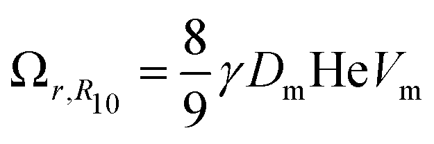 | (4) |
4.2 Bubble average growth rate in foams
Von Neumann12 and more recently Mc Pherson and Srolovitz28 have shown that in extremely dry 2D and 3D foams (ϕ → 0), the number of neighbors of a bubble determines the curvature of its interfaces and thus, the Laplace pressure differences that drive diffusive gas exchange. Experiments16 and simulations10 have confirmed that the size of 3D bubbles with 13–17 faces remains quasi-stationary in 3D foams, while bubbles with a smaller number of faces shrink, and those with a larger number of faces grow.As long as the liquid fraction remains smaller than a few percent, the foam structure can be represented as a dry polyhedral “skeleton” decorated by slender Plateau borders that contain most of the liquid and that are connected at nodes.1 In this range of ϕ, interbubble gas transfer is dominated by diffusion of gas through the contact films. It is driven by the Laplace pressure differences between neighboring bubbles, which is related to the film curvature. On this basis, and by averaging over suitable distributions of bubble geometries investigated using Surface Evolver simulations,29 Hilgenfeldt et al have predicted a parabolic growth law for the bubble radius R10 of the form of eqn (1), valid for small liquid fraction (dry foams) with a coarsening rate:
| Ωp,R10 = C Ω0f(ϕ) | (5) |
 | (6) |
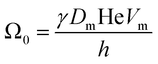
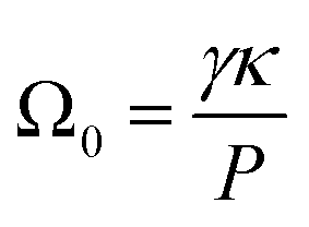
The coarsening constant Ω0 depends on the physicochemical properties of the foaming liquid and is given by:
 | (7) |
 | (8) |
 | (9) |
The constant C introduced in eqn (5) is a geometrical factor depending on the foam structure:29
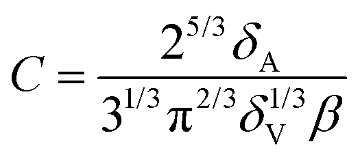 | (10) |
A mean field approach going back to Wagner and Lemlich and reviewed in31,32 may be used to model coarsening in wet foams, in the regime where the interbubble gas transfer is still dominated by the diffusion of gas through the contact films. The volume of a bubble of radius R evolves due to gas exchange via films whose areas are assumed to scale as R2, driven by a Laplace pressure difference proportional to (1/R21 − 1/R), where R21 is the average bubble radius, defined as the ratio of the second and the first moment of the bubble size distribution. This specific ratio which arises from mass conservation of the gas species, sets the critical radius for a bubble of radius R to shrink or grow.13 This writes32,33:
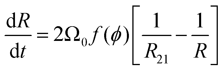 | (11) |
| Ωp,R21 = Ω0f(ϕ) | (12) |
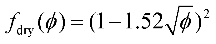
Recent theoretical work derived f(ϕ) for arbitrary polydispersity and for liquid fractions up to the jamming point.34 The average contact area of a bubble normalized by the surface area of a sphere of the same volume as the bubble is predicted to be, for 0 < ϕ ≤ ϕrcp:34
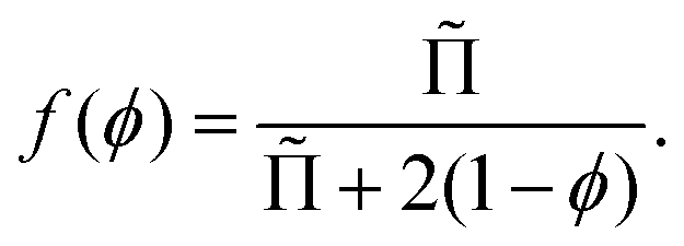 | (13) |
![[capital Pi, Greek, tilde]](https://www.rsc.org/images/entities/char_e12e.gif) is the foam osmotic pressure, normalized by γ/R32, where R32 is the Sauter mean radius. The following empirical relation describes experimental and simulation data for disordered foams over the full range of foam liquid fractions:35
is the foam osmotic pressure, normalized by γ/R32, where R32 is the Sauter mean radius. The following empirical relation describes experimental and simulation data for disordered foams over the full range of foam liquid fractions:35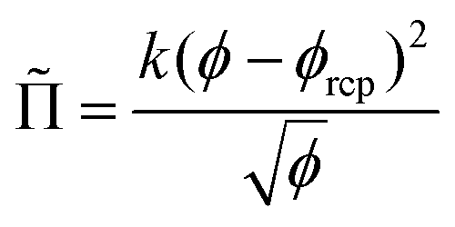 | (14) |
For a disordered assembly of monodisperse bubbles ϕrcp = 0.36, k = 3.2. In polydisperse foams, both ϕrcp and k are modified, as will be discussed in the Section 4.4. Note that eqn (13) is in good agreement with fdry(ϕ) for dry foams, but in contrast to an extrapolation of fdry(ϕ), it vanishes at ϕ = ϕrcp as expected. Indeed, f(ϕ) being the fraction of the bubble surface covered by films it should vanish at ϕ = ϕrcp in the absence of adhesion.
As pointed out by Mullins,14 the successful prediction of the parabolic form of the bubble growth law by mean field models relies on the scaling state where statistical geometric properties of the bubble packing are invariant in time. In the next section, we consider the vicinity of the jamming transition where the film area vanishes and gas transfer occurs between close-by nearly spherical bubbles.
4.3 Coarsening of foam near the jamming transition
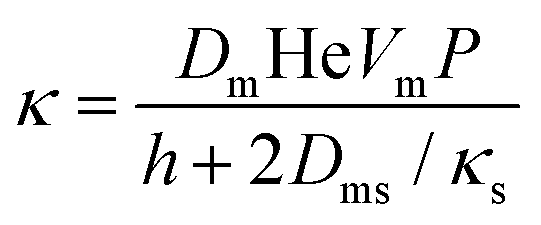
Near the jamming transition, at liquid fractions slightly larger than ϕrcp, neighboring bubbles do not touch and do not form contact films. In the absence of gravity, they are therefore approximately spherical, but in contrast to the dilute limit considered in the LSW theory, the gap separating the surfaces of neighboring bubbles is much smaller than a typical bubble radius. Accurate theories of coarsening in this regime are so far not available. However, the gas transfer between two bubbles that nearly touch has been investigated. Schimming and Durian have derived an expression for the diffusive gas transfer between two neighboring spherical bubbles of radii R1 and R2 immersed in a liquid.36 For two bubbles of similar size R1 ≈ R2 ≈ R and a minimal distance separating the bubbles that we will take equal to h, assuming R ≫ h, the predicted gas volume flow rate is:Qbulk ≈ DmHeVmΔPπR![[thin space (1/6-em)]](https://www.rsc.org/images/entities/i_char_2009.gif) ln(R/h), ln(R/h), | (15) |
At liquid fractions slightly smaller than ϕrcp, the bubbles have on average 6 contacts of area Ac and the gas volume flow rate through each film is:
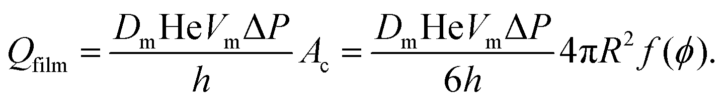 | (16) |
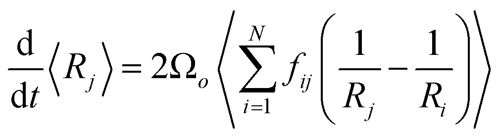
4.4 Requirements for coarsening models beyond the mean-field approximation
The coarsening models discussed successfully predict the exponent of the bubble growth law in foams where gas transfer among bubbles is dominated by diffusion through contact films. They make simplifying assumptions about the foam structure that have the advantage of enabling analytical solutions, but which are too schematic to predict quantitatively the prefactor of the bubble growth law and its dependence on liquid fraction, especially in wet foams, as we will show in the following sections. We therefore revisit the derivation of the models for liquid fractions that are so large that the bubble shape is approximately spherical, but still small enough for diffusion through contact films to be the dominant mechanism of gas transfer among neighboring bubbles. Lemlich's model presented in Section 4.233 is based on a mean field approximation, where every bubble exchanges gas with a fictive bubble of average size, while Hilgenfeldt et al29 use empirical expressions for the bubble contact area and the Laplace pressure, derived from simulation for nearly dry foams: these expressions cannot be extrapolated to wet foams, whose structure is fundamentally different. To investigate how such models could be improved to obtain more quantitative predictions, we start from a representation of a wet foam as a packing of approximately spherical bubbles, as Lemlich does, but we do not make a mean field approximation and our discussion is not limited to the scaling state. We label bubbles by integer indices i or j, ranging from 1 to the total number of bubbles in the foam that we call N. The rate at which the volume of a gas bubble number j, of radius Rj changes with time is in this case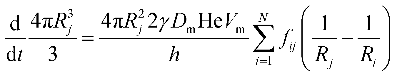 | (17) |
 | (18) |
 | (19) |
To compare eqn (18) with Hilgenfeldt's mean field model we write this equation as:
 | (20) |
 | (21) |
From eqn (5), (7), (10) and (20), we see that in the wet case, the factor 1/β* plays the role of the factor 1/β in the dry case.
To summarize, the coarsening process depends on the average Laplace pressure difference with respect to the neighbors of each bubble (i.e. the contact film curvature), as well as on the respective contact areas. Our analysis shows that to model foam coarsening quantitatively, these features must not be averaged independently, their correlation matters, and it can be expected to depend on liquid fraction and polydispersity. A deeper understanding of the packing geometry of wet coarsening foams is thus needed, simulations investigating this are under way. Eqn (20) also shows that in the scaling state where all ratios of characteristic lengths of the structure are invariant in time, β* is independent of time, as expected.
5 Discussion and comparison with models
5.1 Coarsening rate in the adhesive foam regime ϕ ≤ ϕ*
Fig. 4 shows the decrease of the coarsening rate Ωp,R32 as the liquid fraction approaches ϕ*. Because the coarsening exponent 1/2 is a signature of gas transfer through contact films between bubbles, we conclude that such films persist above ϕrcp up to ϕ*. We attribute this to adhesive bubbles interactions that promote contact films evidenced by the observations reported in Section 3.2. For ϕ < ϕrcp, the film area is expected to be set by the osmotic pressure predicted for non-adhesive foams by (eqn (13)), because here, capillary contact forces dominate over adhesive forces. In contrast, for ϕrcp ≤ ϕ ≤ ϕ*, the film size is maintained at a non-zero value due to attractive interactions. We will discuss each of these two regimes in the following.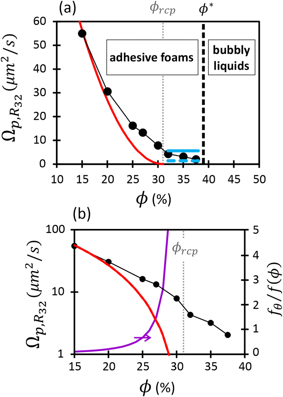 | ||
| Fig. 4 Coarsening rates for wet foams presented in linear scale (a) and logarithmic scale (b), as a function of liquid fraction. The plotted parameter is called Ωp,R32 in the text. The red line represents the theoretical prediction, i.e.eqn (12) and (13), evaluated as explained in the text with ϕrcp = 31%, k = 4.75. The horizontal blue lines correspond to the expected coarsening rates due solely to adhesion-induced contact films between bubbles (see eqn (27)), assuming respectively 12 (continuous line) and 3 (dashed line) contacts per bubble. In (b), the purple curve represents the ratio of film areas induced solely by adhesion forces (eqn (27)) and those induced solely by the osmotic pressure (eqn (13)). | ||
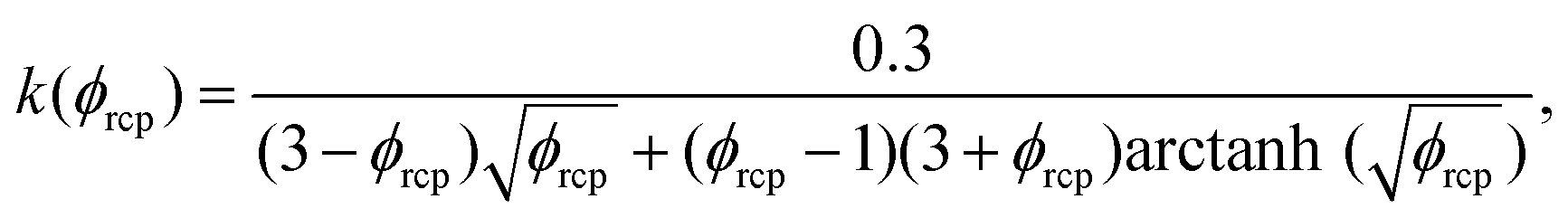
If attractive bubble interactions are negligible, the fraction of bubble interfaces covered by contact films can be expressed as a function of the osmotic pressure using eqn (13). For monodisperse or weakly polydisperse foams where the random close packing fraction is ϕrcp ≈ 36% the empirical expression eqn (14) can be used to predict . However, for our strongly polydisperse samples where ϕrcp is close to 31%, this model has to be generalized. The change of ϕrcp implies a change of the parameter k in eqn (14). To explain this, we briefly revisit the derivation of eqn (14). The factor ϕ−1/2 which dominates the variation of osmotic pressure with liquid fraction in the dry limit is set by the geometry of Plateau borders and the Laplace law,2 the functional form of the factor (ϕ–ϕrcp)2 which dominates in the wet limit is derived empirically. The coefficient k could simply be fitted to experimental osmotic pressure data, but this would make it impossible to predict the osmotic pressure for samples with polydispersities where such data have not been measured previously. If only ϕrcp is known for such a structure, k can be estimated from a theoretical constraint which has been derived by Princen.37 As recalled in detail in appendix B of ref. 35 it is a direct consequence of the definition of osmotic pressure in a foam −γΠdVliquid = γdA, relating the work required to extract a liquid volume dVliquid from a foam to the resulting change of interfacial energy, for a fixed total volume of the bubbles. We get:
 | (22) |
 | (23) |
These results can be used to estimate contact areas for polydisperse foams in the absence of attractive bubble interactions (contact angle zero) using eqn (13). As shown in the Section 3.2, there is evidence of attractive bubble interactions in our samples. As a consequence, the angle between interfaces meeting at a contact is increased, leading to an enhanced contact area. We expect this effect to become negligible in dry foams where contact areas are large and we will discuss the impact of this effect at the end of this section.
We have compared the measured coarsening rates for ϕ < ϕrcp = 31% to that predicted by Lemlich model eqn (12) with the film area given by eqn (13), (14) and (23). For the comparison, the predicted Ωp,R21 must be multiplied by f(ϕ = 15%)(R32/R21)2. This scaling is justified since in the scaling state, the ratio R32/R21 does not depend on the liquid fraction as shown in Table 1. We observe in Fig. 4 that the decrease of Ωp,R32 with ϕ is much slower than predicted. This is likely due to bubble adhesion which increases the area of contact films. This effect is most striking at ϕrcp where, in the absence of attractive interactions, the contact area should be zero, while a finite contact area will persist for positive contact angles as will be discussed in Section 5.1.2.
Let us now compare the value of the observed growth rate to the rate predicted by Lemlich for ϕ = 15%. This is the smallest investigated liquid fraction where the effect of adhesion is expected to be negligible. We get Ω0 = Ωp,R32(R21/R32)2/f(15%) ≈ 214 ± 21 μm2 s−1. This value can be compared to that previously measured in quasi two-dimensional foams maintained at a constant capillary pressure, comparable to those in the current experiments.38 In this work, the finite liquid fraction corrections proposed by Schimming and Durian36 were used, leading to Ω0 = 256 μm2 s−1. This is in good agreement with the value measured in 3D foams, taking into account experimental uncertainties and the possible limitations of the models used.
Besides the film area, another major feature of the foam structure that determines coarsening rates is the average thickness of contact films. It results from an equilibrium between the film disjoining pressure Πdisj and the capillary pressure Pc that sets the difference between the liquid pressure in the Plateau borders and the gas pressure in the bubbles. For a foam, in the absence of adhesion or when it can be neglected as it is the case for ϕ < ϕrcp, the capillary pressure is given by:34
 | (24) |
In the range 15% ≤ ϕ ≤ 30%, for average bubble sizes in the range 60 μm < R32 < 800 μm, the capillary pressure typically varies between 100 Pa and 1500 Pa.
Previous measurements of the disjoining pressure of films made with TTAB solutions at the cmc showed that they are common black films and that the disjoining pressure is well predicted by DLVO theory39: Πdisj is the sum of a van der Waals attraction (air/water/air Hamaker constant 3.7 × 10⁻²⁰ J) and of an electrostatic repulsion with a surface potential Ψo = 130 mV. We assume that these findings apply to our foams when ϕ < ϕrcp. The Debye electrostatic screening length λD is a function of the solution ionic strength. In our experiments, the concentration is about four times larger than the cmc. Therefore, the ionic strength results from the contribution of the surfactant species up to the cmc and a contribution of the fraction α of free counterions that are not bound to the micelles. The following expression has been proposed for a 1:1 electrolyte40:
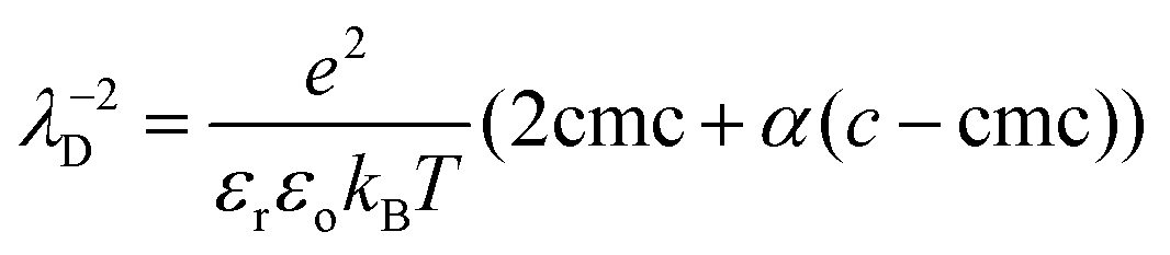 | (25) |
By solving the equation Πdisj = Pc, we predict the equilibrium film thickness heq as a function of R32 and ϕ. For a given ϕ, as the bubble radius R32 increases during coarsening, the capillary pressure will decrease and therefore the film thickness is expected to increase since Πdisj decreases with film thickness. The analysis shows that, for each liquid fraction, the film thickness slightly increases with R32 as heq ∼ R320.15. In view of our measurement accuracy (cf.Fig. 2), this small dependency is too small to be resolved experimentally. Moreover, the relative increase of heq with liquid fraction varying between 15% and 30% is of the order of 2%. We conclude that in the range of investigated liquid fractions and bubble radii corresponding to Fig. 2, the film thickness can be considered to a good approximation as constant. Our calculation for the equilibrium film thickness gives heq ≈ 35 ± 3 nm.
We now discuss the gas permeability of the films. To estimate it for air, which is a mixture of nitrogen and oxygen, we recall that the inverse of this permeability is the sum of the inverse permeabilities of the two gases weighted by their relative proportions.1,30 Taking the values of He and Dm for di-nitrogen and di-oxygen gases given in the literature,42,43 we obtain an effective value for DmHe of 1.46 × 10⁻¹⁴ mol m−1 s−1 Pa−1. Neglecting any resistance to gas transfer from the adsorbed monolayers, using eqn (7) and heq = 35 nm, we predict Ω0 ≈ 390 μm2 s−1. This is somewhat larger than the values deduced from the experiments (i.e. 214 μm2 s−1). Note that we did not consider any permeability reduction due to the interfacial layers.
Let us now discuss a feature that may be missing in previous coarsening models, besides those pointed out in Section 4.4. The film thicknesses in foams could be larger than the equilibrium thicknesses, because during bubble rearrangements, some films disappear and others are created, initially with a thickness much larger than the equilibrium value; this effect will slow down coarsening if the time it takes to thin down a new film to the equilibrium thickness is comparable or longer than the average time between successive rearrangements for a given bubble in the foam. A slowing down of foam coarsening has indeed been reported recently in foams under shear, above a shear rate corresponding to a time interval between shear induced rearrangements.44 Analyses of multiple light scattering data acquired during the coarsening experiments on the ISS are under way to measure the rate of rearrangements, and to determine whether they can affect the coarsening rates.
At the liquid fraction ϕrcp, bubbles in a foam without adhesive interactions no longer exert forces on each other, the areas of the contact films between neighbors shrink to zero. Gas can be transferred among neighboring bubbles only through the bulk liquid, over distances typically much larger than a contact film thickness. Therefore, the coarsening process is expected to slow down significantly, compared to dryer foams.
In foams where interactions are adhesive, at liquid fractions ϕ ≥ ϕrcp, neighboring bubbles spontaneously form contact films of typical area Ac. The energy cost of deforming the bubbles and increasing their surface area is compensated by the gain AcF where F is the energy of adhesion per unit surface. F also determines the contact angle θ at which the interfaces of neighboring bubbles meet, via the Young Dupré relation F = 2γ(cosθ − 1). Fig. 5 illustrates this in the case of two adhesive 3D bubbles in contact. We consider this configuration as a minimal model of a bubble cluster, with two bubbles of slightly different radii R1 and R2, both close to their average R. A simple geometrical calculation shows that for this system, the contact area is Ac = πR2sin2θ.
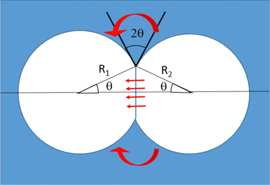 | ||
| Fig. 5 Side view of two adhesive bubbles, of radii R2 < R1, both very close to their average R. In this schematic illustration, the contact angle θ is much larger than the value that we determined experimentally and that we consider in our model, and the radii are too close to be distinguished. The red arrows illustrate diffusive gas flow driven by the Laplace pressure difference, which can occur through the contact film as well as through the bulk liquid surrounding it. | ||
We will first discuss whether in such a bubble cluster the gas transfer among the bubbles is dominated by gas flow through the surrounding bulk liquid or through the contact film.
Eqn (16) estimates the gas flow through contact films as a function of the difference of capillary pressures between two bubbles ΔP = 2γ(1/R1 − 1/R2) and under steady state conditions. Here, using Ac = πR2sin2θ, eqn (16) becomes:
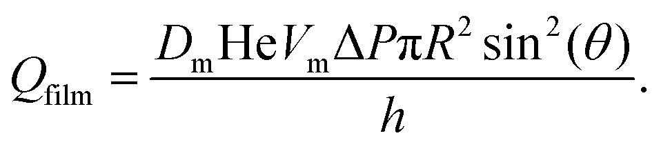 | (26) |
In the case of repulsive interactions where the contact angle is θ = 0 and thus Ac = 0, the gas transfer between two spherical neighboring bubbles that almost touch, with a minimal separation h, must occur through the bulk, in the meniscus surrounding the region where bubbles come close to each other. The flow rate Qbulk in this case is given by eqn (15).
Fig. 6 compares Qfilm to Qbulk, for several contact angles, near the one we have measured experimentally. The figure illustrates that for any given contact angle of the order of a few degrees, in the limit of large ratios between the bubble radius and the liquid gap h between neighboring bubbles, the gas transfer through the contact film will always become larger than the gas transfer through the bulk one would expect for repulsive bubbles with the same gap. Indeed, the ratio of the two transfer rates scales as (R/h)/ln(R/h). For a contact angle close to 4°, gas transfer through the films becomes dominant for bubble radii more than ≈1500 times the film thickness. For an equilibrium film thickness of the order of 40 nm, the critical bubble radius is thus of the order of 60 μm. Fig. 6 suggests that in our coarsening experiments where R > 60 μm, the gas transfer is dominated by diffusive flow through films even at liquid fractions larger than ϕrcp, in agreement with the observed coarsening exponent close to 1/2.
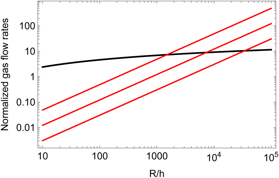 | ||
| Fig. 6 The gas transfer among two neighboring bubbles of similar sizes is plotted assuming either transfer going through a contact film (red lines, eqn (26)) or through the bulk liquid surrounding the meniscus (black line, eqn (15)). The contact angles assumed in the cohesive case are, from top to bottom, 4, 2 and 1°. All the flow rates are normalized by πRDmHeVmΔP. | ||
Next, to estimate the coarsening rates, we recall that the function f(ϕ) in eqn (13) represents the fraction of the bubble area covered by liquid films and vanishes for ϕ ≥ ϕrcp. Here, we assume weak adhesion forces between contacting bubbles, so that f(ϕ) = fθ for ϕ ≥ ϕrcp. We estimate fθ for ϕ ≥ ϕrcp using the following relation:
 | (27) |
The coarsening of adhesive foams raises many challenging theoretical questions whose solution is beyond the scope of the present paper. Coarsening generally amplifies the difference between the radii of neighboring bubbles. The contact film separating bubbles of different sizes is therefore increasingly curved. Moreover, adhesion reduces the interfacial tension in the contact film, which enhances the curvature. Therefore, for a given perimeter, the curvature of the contact film enhances its area and thus the efficiency of gas transfer through it. To predict the evolution of bubble clusters or foams due to coarsening, the geometry of contact films needs to be investigated in detail. In addition, a detailed investigation of the gas transfer through the bulk liquid near the contact line would be of interest, depending on the contact angle. Yet another important question concerns the connectivity of the flocculated bubble clusters that are expected at liquid fractions larger than ϕ*. The network of contacts must evolve as the gas in smaller bubbles is transferred to larger bubbles. Depending on liquid fraction, the contact network might percolate so that all bubbles are connected to each other, or it might split up into independent clusters. In each of these clusters, all the gas will ultimately be accumulated in a single remaining bubble, and if these bubbles remain unconnected, there would no longer be any effect of adhesion in the limit of a long coarsening time. Bubbles in clusters with multiple adhesive contacts may have a distorted shape that can no longer be modeled as a sphere. This feature and its effect on coarsening could be studied using simulations based on the Surface Evolver software.
In contrast to our results, a progressive transition of the coarsening law exponent from 1/2 to 1/3 over a liquid fraction interval 23% < ϕ < 38% has been reported by Isert et al in a foam coarsening experiment, where drainage was suppressed by magnetic levitation.45 The transition onset was observed at much lower ϕ, compared to our results. This could partly be due to a systematic underestimation of ϕ, mentioned by the authors,46 shifting the onset of the transition to 25%. The discrepancies could also be due to the use of a highly concentrated SDS surfactant solution, for which the contact angle could be significantly smaller than for TTAB. A different analysis of our data and of those of Isert et al has been proposed by Durian47 to explain the change of the coarsening exponent with liquid fraction, based on an ad hoc expression of the contact film radius dependence on liquid fraction.
To assess if foam coarsening modified by adhesion is observable on Earth, we consider a foam column floating on a liquid reservoir. At the top of the column, the cumulated buoyancy forces of the bubbles below tend to dominate over adhesive forces. At the bottom, the buoyancy force pushing bubbles against their neighbours above is ρg4πR3/3; the contact area due to this force is estimated by dividing it by the capillary pressure 2γ/R. This may be compared to the contact area solely due to adhesion in the absence of gravity Ac = πR2sin2(θ) ≈ πR2θ2 for θ ≪ 1 considered here (cf.Fig. 5). The contact areas induced by either gravity or adhesion are equal if  , where the Bond number is Bo = ρgR2/γ. For γ = 37.1 mN m−1 and a typical bubble radius R = 100 μm, we have θ ≈ 3° on Earth and θ ≈ 0.003° in the ISS. Therefore, the effect of a small contact angle of 4° characteristic of our foaming solution cannot be easily detected in typical 3D bulk foam coarsening experiments on Earth whereas it is revealed under microgravity. Moreover, the adhesive networks for liquid fractions ϕrcp < ϕ < ϕ* could be difficult to observe on Earth. Gravity induced creaming may crush these structures until their liquid fraction approaches ϕrcp.
5.2 Coarsening rates in bubbly liquids ϕ > ϕ*
At liquid fractions beyond the dilute limit, the average distance between bubbles decreases. Therefore, concentration gradients of the gas dissolved in the continuous phase do not extend independently up to an infinite distance around each bubble as assumed in the LSW theory, but over a shorter distance. As a consequence, the coarsening rate is expected to increase as ϕ decreases. Such an effect has been observed in annealing alloys and in emulsions, as discussed in Section 4.To compare the measured coarsening rates Ωc,R32 to those predicted for the mean radius growth law of concentrated particle dispersions, we must take into account the polydispersity which, in this regime, evolves with liquid fraction. From measurements of the bubble size distributions,21 we determined the geometrical coefficient Co = (R32/R10) for each ϕ (see Table 1). We then calculated the coarsening rate Ωc,R10 = Ωc,R32/Co3. These rates are much larger than the rate expected in the dilute limit (eqn (4)): Ωr = 12.1 μm3 s−1.
In Fig. 7, we show the measured values for Ωc,R10 together with predictions from various simulations and theories.5 We see that most of them predict coarsening rates much smaller than the measured ones, except for the MLSW model.
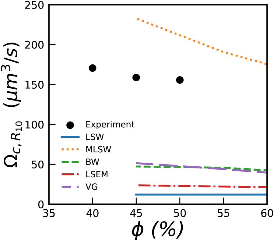 | ||
| Fig. 7 Coarsening rate Ωc,R10 for bubbly liquids versus liquid fraction. The lines show numerical predictions yielded by 5 theories presented in reviews.5,49 They provide predictions only down to 45%. | ||
Experiments with emulsions showed that their coarsening rate was extremely dependent on the surfactant. Variations by several orders of magnitude for a given ϕ, have been reported48 and attributed to exchanges between drops during collisions.
6 Conclusion
Our experiments under microgravity show that during wet foam coarsening the average bubble radius increases with time as t1/2 as in dry foams. The transition towards the Ostwald ripening regime (average bubble growth as t1/3) is rather sharp and occurs at a liquid fraction close to ϕ* = 39%, higher than expected for the jamming transition of monodisperse hard spheres, ϕ* ≈ 36% and far above the random close packing fraction ϕrcp ≈ 31% of spheres packing with the polydispersity of the coarsening wet foams in the scaling state. We deduced consistently the value of ϕrcp from simulations of polydisperse sphere packings21 and from a previous theoretical model, both linking ϕrcp to the experimentally observed polydispersity.3At liquid fractions below 25%, the observed coarsening rates agree approximately with previous models, the differences may be due to the contribution of the surfactant monolayers to film permeability, to non equilibrium films with enhanced thickness or to the mean field approximations used in the models. At liquid fractions larger than 25% and in particular near ϕrcp the coarsening rates are much larger than predicted by coarsening models where only gas transfer through films is considered. This cannot be due to gas transfer through bulk liquid whose importance is expected to increase with ϕ, because such a contribution would be inconsistent with the coarsening exponent of 1/2 that we observe up to 39% and which is characteristic of gas transfer through films. We attribute these features at least partially to a weak attractive interaction between the bubbles, which we evidenced in dedicated ground based experiments. Adhesion is expected to enhance contact film areas for ϕ > ϕrcp and to give rise to a loose gel-like network of bubbles connected by contact films, observable only in the absence of gravity. The sharp transition to Ostwald ripening behavior at ϕ ≈ ϕ*, and the prefactor of the coarsening law in this latter regime which is much larger than predicted by most theories, call for further investigations.
Experiments with systems with adhesive forces larger than in our present samples are planned in future ISS experiments to take place in 2023. Numerical modeling is also under way to account for the new observed features.
Author contributions
M. Pasquet, E. Rio, A. Salonen, D. Langevin, S. Cohen Addad, R. Höhler and O. Pitois contributed to the preparation and follow-up of the ISS experiments. M. Pasquet, N. Galvani and O. Pitois performed the image analysis. M. Pasquet, N. Galvani, O. Pitois and S. Cohen-Addad performed the calculations of the coarsening rates using the different models. S. Cohen-Addad performed the film thickness calculations, R. Höhler performed the ground experiments and the theoretical modelling. All the authors participated in the discussions and writing of the manuscript.Conflicts of interest
There are no conflicts to declare.Appendix
Fig. 8 illustrates the liquid fraction dependence of the coarsening exponents.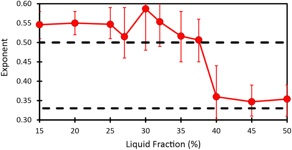 | ||
| Fig. 8 Figure showing the evolution as a function of liquid fraction of the exponent obtained by fitting power law R32 = atα on data in the scaling state. | ||
Fig. 9 illustrates the dependency of the coefficient k defined in eqn (14) on the jamming liquid fraction ϕrcp, predicted by a calculation described in Section 5.1.1. Combined with eqn (23), this result enables the prediction of the osmotic pressure of polydisperse foams and emulsions, a result which may be useful well beyond the scope of our present study.
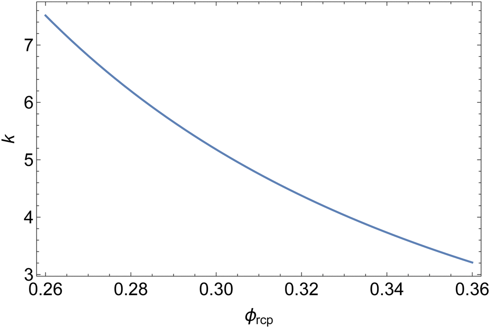 | ||
| Fig. 9 Coefficient k defined in eqn (14)versus the jamming liquid fraction ϕrcp. | ||
Acknowledgements
This work was supported by ESA and CNES, focused on the Soft Matter Dynamics instrument and the space mission Foam-C. Marina Pasquet, Nicolo Galvani and Alice Requier benefited from CNES and ESA PhD grants. The authors are grateful to the BUSOC team for their invaluable help during the ISS experiments. We also want to warmly thank Marco Braibanti and Sébastien Vincent-Bonnieu from ESA, Christophe Delaroche from CNES and Olaf Schoele-Schulz from Airbus for their continuing support.Notes and references
- D. Weaire and S. Hutzler, The Physics of Foams, Clarendon Press, Oxford, 1999 Search PubMed.
- I. Cantat, S. Cohen-Addad, F. Elias, F. Graner, R. Höhler, O. Pitois, F. Rouyer and A. Saint-Jalmes, Foams: structure and dynamics, OUP, Oxford, 2013 Search PubMed.
- R. S. Farr and R. D. Groot, J. Chem. Phys., 2009, 131, 244104 CrossRef PubMed.
- S. S. Datta, D. D. Gerrard, T. S. Rhodes, T. G. Mason and D. A. Weitz, Phys. Rev. E: Stat., Nonlinear, Soft Matter Phys., 2011, 84, 041404 CrossRef PubMed.
- A. Baldan, J. Mater. Sci., 2002, 37, 2171–2202 CrossRef CAS.
- H. Princen, J. Colloid Interface Sci., 1983, 91, 160–175 CrossRef CAS.
- V. Trappe, V. Prasad, L. Cipelletti, P. Segre and D. A. Weitz, Nature, 2001, 411, 772–775 CrossRef CAS PubMed.
- P. L. Fuhrmann, S. Breunig, G. Sala, L. Sagis, M. Stieger and E. Scholten, J. Colloid Interface Sci., 2022, 607, 389–400 CrossRef CAS PubMed.
- J. Dong, F. Turci, R. L. Jack, M. A. Faers and C. P. Royall, J. Chem. Phys., 2022, 156, 214907 CrossRef CAS PubMed.
- G. L. Thomas, J. M. Belmonte, F. Graner, J. A. Glazier and R. M. De Almeida, Colloids Surf., A, 2015, 473, 109–114 CrossRef CAS PubMed.
- P. Taylor, Adv. Colloid Interface Sci., 1998, 75, 107–163 CrossRef CAS.
- J. Von Neumann, Am. Soc. Met., 1952, 108, 108–110 Search PubMed.
- C. Wagner, Z. Elektrochem., 1961, 65, 581–591 CrossRef CAS.
- W. Mullins, J. Appl. Phys., 1986, 59, 1341–1349 CrossRef CAS.
- D. J. Durian, D. Weitz and D. Pine, Phys. Rev. A: At., Mol., Opt. Phys., 1991, 44, R7902 CrossRef CAS PubMed.
- J. Lambert, I. Cantat, R. Delannay, R. Mokso, P. Cloetens, J. A. Glazier and F. Graner, Phys. Rev. Lett., 2007, 99, 058304 CrossRef PubMed.
- I. M. Lifshitz and V. V. Slyozov, J. Phys. Chem. Solids, 1961, 19, 35–50 CrossRef.
- P. Born, M. Braibanti, L. Cristofolini, S. Cohen-Addad, D. Durian, S. Egelhaaf, M. Escobedo-Sánchez, R. Höhler, T. Karapantsios and D. Langevin, et al. , Rev. Sci. Instrum., 2021, 92, 124503 CrossRef CAS PubMed.
- NASA, Acceleration environment, 2015, https://www.nasa.gov/sites/default/files/atoms/files/acceleration-environment-iss-mini-book_detail-508c.pdf.
- M. Pasquet, N. Galvani, O. Pitois, S. Cohen-Addad, R. Höhler, A. T. Chieco, S. Dillavou, J. M. Hanlan, D. J. Durian and E. Rio, et al. , C. R. Mec., 2023, 351, 1–23 Search PubMed.
- N. Galvani, M. Pasquet, M. Mukherjee, A. Requier, S. Cohen-Addad, O. Pitois, R. Höhler, E. Rio, A. Salonen, D. Durian and D. Langevin, arXiv, 2023, preprint, arXiv:2304.11543.
- J. Seknagi, PhD thesis, Sorbonne Universite, 2022.
- A. M. Kraynik, D. A. Reinelt and F. van Swol, Phys. Rev. Lett., 2004, 93, 208301 CrossRef PubMed.
- F. Huisman and K. J. Mysels, J. Phys. Chem., 1969, 73, 489–497 CrossRef CAS.
- P. Kralchevski, A. Nikolov, D. Wasan and I. Ivanov, Langmuir, 1990, 6, 1180–1189 CrossRef CAS.
- A. Brailsford and P. Wynblatt, Acta Metall., 1979, 27, 489–497 CrossRef CAS.
- S. Ariyaprakai and S. R. Dungan, J. Colloid Interface Sci., 2010, 343, 102–108 CrossRef CAS PubMed.
- R. Mc Pherson and D. Srolovitz, Nature, 2007, 446, 1053–1055 CrossRef PubMed.
- S. Hilgenfeldt, S. A. Koehler and H. A. Stone, Phys. Rev. Lett., 2001, 86, 4704 CrossRef CAS PubMed.
- H. Princen and S. Mason, J. Colloid Sci., 1965, 20, 353–375 CrossRef CAS.
- P. Stevenson, Curr. Opin. Colloid Interface Sci., 2010, 15, 374–381 CrossRef CAS.
- O. Pitois, Foam Engineering, ed. P. Stevenson, Wiley-Blackwell, Chichester, 2012, ch. 4, pp. 59–73 Search PubMed.
- R. Lemlich, Ind. Eng. Chem. Fundam., 1978, 17, 89–93 CrossRef CAS.
- R. Höhler, J. Seknagi and A. Kraynik, Soft Matter, 2021, 17, 6995–7003 RSC.
- A. Maestro, W. Drenckhan, E. Rio and R. Höhler, Soft Matter, 2013, 9, 2531–2540 RSC.
- C. D. Schimming and D. J. Durian, Phys. Rev. E, 2017, 96, 032805 CrossRef CAS PubMed.
- H. M. Princen, Langmuir, 1986, 2, 519–524 CrossRef CAS.
- E. Forel, E. Rio, M. Schneider, S. Beguin, D. Weaire, S. Hutzler and W. Drenckhan, Soft Matter, 2016, 12, 8025–8029 RSC.
- V. Bergeron, Langmuir, 1997, 13, 3474–3482 CrossRef CAS.
- R. Pashley and B. Ninham, J. Phys. Chem., 1987, 91, 2902–2904 CrossRef CAS.
- T.-M. Perger and M. Bešter-Rogac, J. Colloid Interface Sci., 2007, 313, 288–295 CrossRef CAS PubMed.
- R. Sander, Atmos. Chem. Phys., 2015, 15(8), 4399–4981 CrossRef CAS.
- R. T. Ferrell and D. M. Himmelblau, J. Chem. Eng. Data, 1967, 12, 111–115 CrossRef CAS.
- A. Saint-Jalmes and C. Trégouët, Soft Matter, 2023, 19, 2090–2098 RSC.
- N. Isert, G. Maret and C. M. Aegerter, Eur. Phys. J. E: Soft Matter Biol. Phys., 2013, 36, 1–6 CrossRef PubMed.
- N. Isert, G. Maret and C. M. Aegerter, Colloids Surf., A, 2015, 473, 40–45 CrossRef CAS.
- D. J. Durian, arXiv, arXiv:2304.00415 [cond-mat.soft].
- K. Roger, U. Olsson, R. Schweins and B. Cabane, Angew. Chem., 2015, 127, 1472–1475 CrossRef.
- K. Mahalingam, B. P. Gu and G. J. Liedl, Acta Metall., 1987, 35, 16 CrossRef.
| This journal is © The Royal Society of Chemistry 2023 |