
 Open Access Article
 This Open Access Article is licensed under a
 Creative Commons Attribution 3.0 Unported Licence
Temperature reconfigurable skyrmionic solitons in cholesteric liquid crystals†
Yuan
Shen
 ,
Maryam
Qaiser
and
Ingo
Dierking
*
,
Maryam
Qaiser
and
Ingo
Dierking
*
Department of Physics, School of Natural Sciences, University of Manchester, Oxford Road, Manchester M13 9PL, UK. E-mail: ingo.dierking@manchester.ac.uk
First published on 22nd November 2023
Abstract
In this work, a reversible transformation between torons and cholesteric fingers is realized by continuously changing the pitch through temperature variation of the chiral nematic liquid crystal twist inversion system. By decreasing the pitch, the torons act as seeds from which cholesteric fingers gradually grow. By increasing the pitch, the cholesteric fingers gradually shorten and transform back to the initial state. We find that although the morphology of the torons is severely deformed and cannot be distinguished during the heating–cooling loops, the torons are very well topologically protected and can hardly be destroyed.
Introduction
Topological solitons, such as skyrmions, baby-skyrmions (also refer to as two-dimensional (2D) skyrmions), are localized topologically nontrivial field configurations embedded in a uniform far-field background that behave like particles.1 Similar to topological defects, these solitons cannot be continuously deformed into a topologically trivial uniform field. They play important roles in different fields of physics, such as vortices in superconductors,2 instantons in quantum theory,3 rotons in Bose-Einstein condensates,4 and skyrmions in magnetic materials5 and liquid crystals.6Liquid crystals are anisotropic fluids with long-range orientational order of elongated molecules defined by the average of the long molecular axis called director, n. The study of solitons in liquid crystals was started in 1968 by Wolfgang Helfrich who theoretically modelled alignment inversion walls as static solitons in an infinite sample of nematic order.7 Since then, different types of solitons have been reported, including different types of inversion walls,7–9 propagating solitary waves,10,11 individual convective rolls12 and local convective domains,13 discommensurations14,15 and breathers,16 nematicons,17 directrons,18 swallow-tail solitons19 and others. In addition, a number of topological solitons, such as skyrmions, torons, hopfions, heliknotons are observed or created in chiral nematic liquid crystals (CNLCs).20–22 The CNLC is represented by a helical superstructure in which the director n continuously twists along a helix at a constant rate. The distance over which n rotates by 2π is defined as a pitch, p.23 The helical structure of CNLCs can be deformed through different ways, such as by applying electric or magnetic fields or by confining CNLCs between surfaces with homeotropic anchoring, which eventually leads to the formation of topological solitons.
In this work, topological solitons of elementary 2D skyrmions capped by two 3D singular point defects termed as “torons” are generated in a CNLC which is confined between two surfaces with homeotropic anchoring. Compared to other broadly investigated CNLC systems, such as the ones obtained by doping chiral dopants into achiral nematics or various derivatives of cholesterol, the CNLC used in our system shows a special property, i.e., its pitch (p) is strongly dependent on the temperature (T). By gradually decreasing the temperature from the isotropic phase, the pitch increases. At a critical temperature, the pitch increases to infinity and the sample unwinds into an achiral nematic. Further decreasing temperature, the sample reverses its chirality from right handedness to left handedness. In the experiment, the sample slowly transforms from the focal conical texture into the fingerprint texture by increasing pitch. Once p is of the size of the cell gap, d, the cholesteric fingers gradually relax into torons. The number of the torons can be easily controlled by manipulating the cooling rate. By gradually increasing the temperature, the torons act as seeds of cholesteric fingers from which those fingers grow. We find that although the morphology of the torons is greatly distorted by changing the temperature, their stability is very well topologically protected.
Materials and methods
The CNLC used is 4-[(S,S)-2,3-epoxyhexyloxy]-phenyl-4-(decyloxy)-benzoate (W46)24,25 which shows an isotropic to nematic phase transition at the clearing point temperature, Tc = 97.5 °C on cooling. All the temperatures from this point on in the paper will be given as reduced temperatures, Tc − T. The CNLC is firstly heated to the isotropic phase and then filled into a cell (North LCD) with homeotropic anchoring. The thickness of the cell, d = 9.7 μm, is measured through the thin-film interference method.26 The pitch of the CNLC gradually increases with decreasing temperature. At Tc – 15 °C to Tc – 15.2 °C, the pitch diverges to infinity (1/p = 0) and the CNLC transform into a nematic phase configuration which is confirmed by a completely dark texture observed in polarizing optical microscopy (POM). This helix inversion point is consistent with the previously published data25 (Fig. 1). The sample then reverses its chirality from right handedness to left handedness at Tc – 15.3 °C which is characterized by the formation of cholesteric fingers and the pitch gradually decreases with further decreasing temperature.25 The sample is observed through a polarizing microscope (Leica OPTIPOL). Images and movies are recorded by using a complementary metal-oxide semiconductor (CMOS) camera (UI-3360CP-C-HQ, uEye Gigabit Ethernet). The sample is temperature controlled in a hot stage (LTSE350, Linkam) which is connected to a TP 94, Linkam temperature controller. All of the quantitative analysis (toron size measurements, number density and percentage area) is done using the image analysis software ImageJ.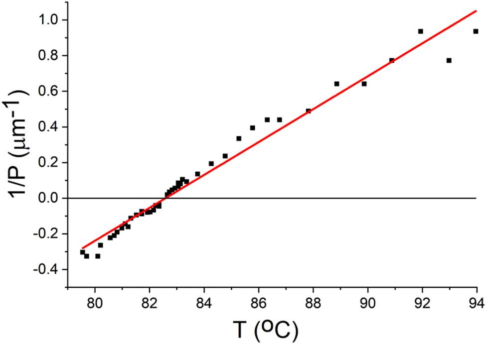 | ||
| Fig. 1 Temperature dependence of the cholesteric pitch (W46) measured by the Cano-Grandjean method. Reproduced with permission ref. 25. Copyright 1993 Talor & Francis. | ||
Results and discussion
As Fig. 2a shows, by slowly decreasing the temperature at a rate of −0.2 °C min−1, the sample firstly experiences the isotropic to cholesteric phase transition at Tc = 97.5 °C. As the pitch continuously increases with decreasing temperature, the sample gradually transforms from the focal conic texture (Tc – 6.3 °C) to the fingerprint texture (Tc – 12.3 °C). Further decreasing the temperature, the cholesteric fingers (CFs) become thicker, start shrinking and some transform into torons (Tc – 13.7 °C). Normally, the fingers of CF1 type are most frequently observed in cells with homeotropic anchoring. However, despite the fact that the fingers of CF2 type do not nucleate from homeotropic anchoring as easily as those of CF1, they do nucleate at dust particles, spacers, or other irregularities27 Furthermore, CF1 and CF2 have a similar look under POM.28 So, it is difficult to determine the type of the CFs at this stage since the CFs here are densely packed together. However, it is reported that CF1 always collapses and disappear by increasing voltage, whereas CF2 can continuously shrink and form torons at high voltages.28 So, we may conclude that both CF1 and CF2 exist in our system, however, only CF2 shrinks and transforms into torons. Fig. 2b shows the schematic director structures of CF1 and CF2, respectively. The CF1 can be represented as a quadrupole composed of two P pairs of the nonsingular λ+1/2 and λ−1/2 disclinations. If one plots a line go through an isolated CF1 along the x-axis and project the director field n along the line onto the order parameter space S2, one can find that the director field can change continuously and eventually shrinks to the north pole of S2.28 On the other hand, an isolated CF2 is composed of a nonsingular λ+1 disclination in the center and two half-integer λ−1/2 disclinations located close to the opposite homeotropic surfaces. The total topological charge Q of CF1 and CF2 are conserved, i.e., Q = 1. However, by projecting the director field of the CF2 along the same line on to the order parameter space S2, one finds that the director field can no longer reduce to the north pole via a continuous transformation.28 Indeed, the fluorescence confocal polarizing microscopy images show that there are two point defects of strength 1 at the two ends of a CF2 segment.27 This configuration is topologically equivalent to the director structure of the torons (Fig. 2b) and may explain the transformation from a shrinking CF2 to a toron. | ||
| Fig. 2 (a) POM images of the sample at different temperatures. The sample is slowly cooled at −0.2 °C min−1 from the isotropic phase. The crossed white arrows represent the polarizers. Scale bar 50 μm. (b) The schematic director structure of a CF1(I), CF2(II) and toron(III). Reprinted with permission from ref. 27 and 29 Copyright 2005 and 2021 American Physical Society. | ||
The topology and structure of CF1, CF2 and torons are closely related and can be transformed between each other. J. Baudry, et. al., demonstrated that a CF2 segment may extend by forming two segments of a CF1 at its two ends.28 Sohn, et. al., showed that a toron could be stretched into a CF2 using laser tweezer.30 At Tc – 14.1 °C, most of the fingers (CF1) disappear due to the unwinding of the helical structure of the CNLC and transform into the uniform homeotropic state. However, some of the fingers (CF2) shrink into torons. The sample texture is stable at Tc – 14.3 °C, and is characterized by a homeotropic background sparsely embedded with torons. Further decreasing the temperature will eventually destroy the torons due to the unwinding of the CNLC system.
It is observed that the number density of the torons that are generated is dependent on the cooling rate of the sample. Fig. 3 shows the sample at the same temperature (Tc – 14.3 °C) but having been cooled at different rates. It is observed that the faster the temperature is decreased, the more torons are generated. The aforementioned phenomenon is quantified in Fig. 4, where average number density per squared millimetres is plotted against cooling rate. It is evident that as the cooling rate decreases, there is a gradual reduction in the number of torons, with the number dropping from approximately 2250 torons per mm2 at −5.0 °C min−1 to about 500 torons per mm2 at −0.2 °C min−1. Consequently, the percentage of the sample covered by torons also exhibits a corresponding, gradual decrease, with the coverage area declining from high to low cooling rates.
 | ||
| Fig. 3 POM images of the CNLC sample at Tc – 14.3 °C which are obtained by cooling the sample from the isotropic phase at different cooling rate. The crossed white arrows represent the polarizers. Scale bar 50 μm. | ||
 | ||
| Fig. 4 Average number density and average percentage area of torons measured at different cooling rates. Inset: Fullwidth Half Maxima of the toron size distribution. | ||
These observations suggest a relationship between cooling rates and toron density, with the latter decreasing as cooling rates decline. It should be noted that in order to obtain the torons the sample here is firstly heated into the isotropic phase and then cooled into the cholesteric phase. In fact, the number of the torons is really dependent on the cooling rate at which the isotropic to cholesteric phase transition is passed. No obvious difference is observed between a sample which is cooled at −5 °C min−1 from the isotropic phase to Tc – 14.3 °C and a sample which is firstly cooled from the isotropic phase to the cholesteric phase at −5 °C min−1, and then gradually cooled (−0.2 °C min−1) to Tc – 14.3 °C. This may be because the stronger symmetry breaking phase transition is induced at the clearing point by the larger cooling rate, thus leading to the formation of more cholesteric fingers.
Fig. 5 displays the size distribution of torons at different cooling rates. The range of the toron sizes slightly increases as the rate of cooling goes from −5.0 °C min−1 to −0.2 °C min−1. The inset in Fig. 4 displays the full width half maxima (FWHM) of the size distribution, which enables one to see a clearer understanding of the distribution's spread. The FWHM graph illustrates that the torons’ size distribution has a gradual upward slope with torons cooled at a higher cooling rate having a narrower FWHM than those cooled at a lower rate. The reason for a variation in size at different cooling rates could be attributed to the toron density. At higher rates, there is a higher toron density and hence a tighter packing of torons in the same sample area, whereas at lower temperatures, with the toron density being lower, there is less interaction between the neighbouring torons, which allows for a greater spread in the size distribution. This information is critical in discerning the differences in toron sizes at various cooling rates, which could be useful in understanding the underlying mechanisms affecting toron formation and behaviour in the sample.
 | ||
| Fig. 5 Size distribution of torons measured at different cooling rates. | ||
To investigate whether torons maintain their size at a given temperature, the sample was cooled to Tc – 14.3 °C where the torons were generated and allowed to stabilise. Snapshots were taken of the sample over the course of 25 minutes at 5 minutes intervals. The size of the torons was measured using the “Analyse Particle” command in ImageJ, in the same way as was done for toron size distribution (Fig. 5). The boxplot in Fig. 6 shows that over a large relaxation period, the sizes distribution of the sample remained relatively the same. This can be seen by the fact that the size of the interquartile range (depicted by the length of the box) is comparable for each time interval and so is the spread of the data, given by the whiskers of the boxplot. Thus, from the snapshots, as well as their quantitative analysis, it can reasonably be concluded that the torons do not change their size over time for a fixed temperature value.
 | ||
| Fig. 6 Variation of toron size over time at a fixed temperature. (a) Snapshots of the sample taken at different times, with the torons enumerated in the second image from left. (b) Toron sizes at different times plotted as a bar chart along with the mean and standard deviation. Scale bar 30 μm. | ||
The samples also show a reversible transformation between torons and CFs. As shown in Fig. 7a, by increasing the temperature, the toron firstly extends radially by deforming the homeotropic regions around it and acts as a seed from which the CFs start to grow. With continuously decreasing the pitch of the sample (increasing the temperature), the core of the toron (the part which includes the two topological point defects) gradually shrinks, distorts and soon the sample transforms into the fingerprint texture (Fig. 7a and Movie 1, ESI†). Surprisingly, even though the toron is greatly distorted and can be hardly distinguished at this stage, it is very well topologically protected and can transform back to its initial state by decreasing the temperature (Fig. 7b and Movie 2, ESI†). The topological charge Q in Fig. 7, which counts the integer number of times that the director field wraps around the order parameter space S2, keeps constant during the transformation.
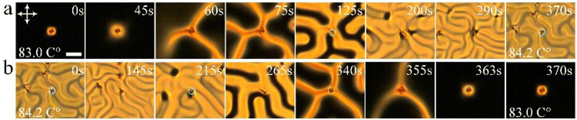 | ||
| Fig. 7 (a) Time series of polarizing micrographs showing the transformation between a toron and cholesteric fingers on decreasing pitch (top row) and (b) back to a toron on increasing pitch (bottom row). The temperature gradually changes at 0.2 °C min−1. The crossed white arrows represent the polarizers. The toron core is highlighted by the green circles. Scale bar 20 μm. | ||
By further increasing the temperature to Tc – 6.9 °C, as shown in Fig. 8, the toron is still stable and can be transformed back from CFs by gradually decreasing the temperature. Apart from that, an additional toron is generated (Movie 3 and 4, ESI†). In this case, the topological charge Q is not conserved due to the nucleation of a new toron. Such a behavior is reasonable because during the transformation, one would expect that new CF2s may nucleate at dusts, spacers or other irregularities.
 | ||
| Fig. 8 (a) Time series of polarizing micrographs showing the transformation between a toron and cholesteric fingers and (b) the formation of another toron. The temperature changes at a rate of 2 °C min−1. The crossed white arrows represent the polarizers. Scale bar 20 μm. | ||
Finally, Fig. 9 depicts a reversible deformation of a 2D lattice composed of torons. By gradually increasing the temperature, the homeotropic regions around the torons are distorted (Fig. 9a, 130s). Form those deformed regions, cholesteric fingers gradually grow. The core of the torons then move in random directions as the fingers elongate (Fig. 9a, 150s). The torons then collide with each other and form aggregates of varied sizes (Fig. 9a, 225s). Eventually, the aggregates continuously shrink (Fig. 9a, 300s) and form a network in which the aggregates are connected via CFs (Fig. 9a, 415s and Movie 5, ESI†).
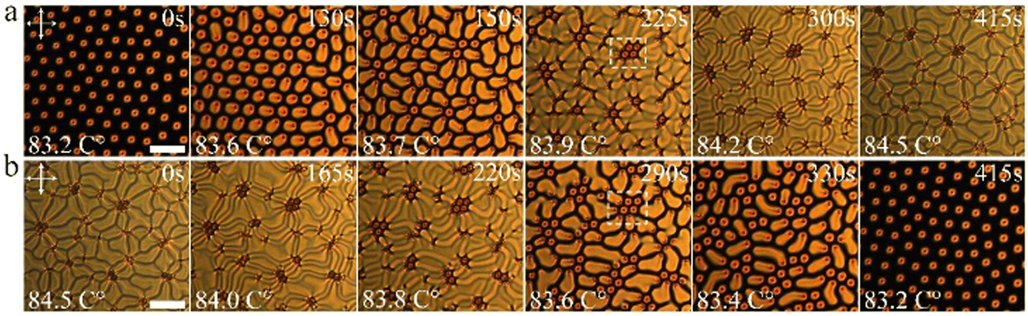 | ||
| Fig. 9 Time series of the polarizing micrographs of the sample. (a) The temperature is gradually increased at a rate of 0.2 °C min−1. (b) The temperature is gradually decreased at a rate of −0.2 °C min−1. The crossed white arrows represent the polarizers. Scale bar 50 μm. | ||
By gradually decreasing the temperature, the aggregates gradually expand, disassemble and eventually transform back to the toron lattice (Fig. 9b and Movie 6, ESI†). It is found that the number of the torons is well preserved within the aggregates. As one can see from one of the aggregates which is indicated by the white dashed square, the aggregate is composed of 8 torons by increasing the temperature (Fig. 9a, 225s) and disassemble into 8 torons by decreasing the temperature (Fig. 9b, 290s). It is also noticed that in some aggregates, the torons in the center of the aggregates do not transform into CFs which may be due to the limited space. Nevertheless, their morphologies are still greatly deformed during the heating–cooling loop. The torons survive through such great morphological deformations, demonstrating their strong topological stability. Since the torons are moving in random directions and some of them can move out of the field of view and torons outside of the field of view can move in during the transformation, one cannot simply count the number of torons in the field of view to determine the conservation of the topological charge of the system. To better quantify the topological stability of the torons against morphological deformations we measured the numbers of torons in individual toron aggregates before heating and after cooling, respectively, as shown in Fig. 10. As we can see, in most cases, Q of toron aggregates keeps constant after a heating–cooling loop. In two cases, Q increases due to the generation of new torons. Only in one case, Q decreases by 1 due to the annihilation of a toron. This demonstrates that the torons are very well topologically protected during the deformations.
 | ||
| Fig. 10 The topological charge Q of different toron aggregates before heating and after cooling. The temperature of the sample changes from Tc −14.5 °C to Tc −6.9 °C and back to Tc −14.5 °C. The insets show a typical toron aggregate with Q = 25 during heating (Tc – 13.7 °C, I) and cooling (Tc – 13.8 °C, II). Scale bars 20 μm. | ||
Conclusions
The formation, structure, dynamics and applications of various topological solitons, including baby skyrmions,31 torons,6,32 hopfions,33,34 twistions35 and heliknotons,22 have received great attention. The transformation between cholesteric fingers and torons have also been investigated in many studies.28–30,36–40 However, in most of those studies, the transformation is induced either by using laser tweezer30 or by tuning the applied electric fields,29,41,42 and thus the pitch of the CNLC almost keeps constant during the transformations. It is unclear how do torons change their structure as the pitch is changing and how well the topological property can be preserved during strong morphological deformations. In this work, we show for the first time the continuous evolution from the focal conic texture to the fingerprint texture and eventually to torons by gradually increasing the pitch of the CNLC system. The number of the generated torons can be facilely controlled by changing the speed of quenching. We further demonstrate that by decreasing the pitch of the CNLC system, the torons can act as seeds of CFs. The stability of the torons is topologically well protected so that even when they are greatly distorted at small cholesteric pitches, the torons can still transform back to the initial state by increasing the pitch of the CNLC system. Our results not only demonstrate that the topological configuration of torons are very well preserved under great structure deformations, but also provide an insight into the dependence of the transformation between torons and cholesteric fingers on pitch. Since topological solitons are receiving increasing attention in superconductors, photonics, magnetic and ferroelectric materials, particle physics, etc., our work may also provide new insights to other physical systems.Conflicts of interest
There are no conflicts to declare.Acknowledgements
Y. S. would like to thank the China Scholarship Council (CSC) for kind support under grant number 201806310129.Notes and references
- N. Manton and P. Sutcliffe, Topological solitons, Cambridge University Press, 2004 Search PubMed.
- A. A. Abrikosov, Rev. Mod. Phys., 2004, 76, 975–979 CrossRef CAS.
- E. V. Shuryak, Nucl. Phys. B, 1982, 203, 93–115 CrossRef.
- D. O’dell, S. Giovanazzi and G. Kurizki, Phys. Rev. Lett., 2003, 90, 110402 CrossRef PubMed.
- U. K. Roessler, A. Bogdanov and C. Pfleiderer, Nature, 2006, 442, 797–801 CrossRef CAS PubMed.
- I. I. Smalyukh, Y. Lansac, N. A. Clark and R. P. Trivedi, Nat. Mater., 2009, 9, 139 CrossRef PubMed.
- W. Helfrich, Phys. Rev. Lett., 1968, 21, 1518–1521 CrossRef CAS.
- L. Leger, Solid State Commun., 1972, 10, 697–700 CrossRef CAS.
- K. B. Migler and R. B. Meyer, Phys. Rev. Lett., 1991, 66, 1485–1488 CrossRef CAS PubMed.
- Z. Guozhen, Phys. Rev. Lett., 1982, 49, 1332–1335 CrossRef CAS.
- L. Lei, S. Changqing, S. Juelian, P. M. Lam and H. Yun, Phys. Rev. Lett., 1982, 49, 1335–1338 CrossRef CAS.
- R. Ribotta, Phys. Rev. Lett., 1979, 42, 1212–1215 CrossRef CAS.
- A. Joets and R. Ribotta, Phys. Rev. Lett., 1988, 60, 2164–2167 CrossRef CAS PubMed.
- M. Lowe and J. P. Gollub, Phys. Rev. A, 1985, 31, 3893–3897 CrossRef CAS.
- M. Lowe, J. P. Gollub and T. C. Lubensky, Phys. Rev. Lett., 1983, 51, 786–789 CrossRef CAS.
- O. A. Skaldin, V. A. Delev and E. S. Shikhovtseva, JETP Lett., 2013, 97, 92–97 CrossRef CAS.
- M. Peccianti and G. Assanto, Phys. Rep., 2012, 516, 147–208 CrossRef.
- O. D. Lavrentovich, Liquid Crystals Rev., 2020, 8, 59–129 CrossRef CAS PubMed.
- Y. Shen and I. Dierking, Mater. Adv., 2021, 2, 4752–4761 RSC.
- P. J. Ackerman, R. P. Trivedi, B. Senyuk, J. van de Lagemaat and I. I. Smalyukh, Phys. Rev. E, 2014, 90, 012505 CrossRef PubMed.
- P. J. Ackerman and I. I. Smalyukh, Phys. Rev. X, 2017, 7, 011006 Search PubMed.
- J.-S. B. Tai and I. I. Smalyukh, Science, 2019, 365, 1449 CrossRef CAS PubMed.
- P.-G. De Gennes and J. Prost, The physics of liquid crystals, Oxford university press, 2nd edn, 1993 Search PubMed.
- D. M. Walba, R. T. Vohra, N. A. Clark, M. A. Handschy, J. Xue, D. S. Parmar, S. T. Lagerwall and K. Skarp, J. Am. Chem. Soc., 1986, 108, 7424–7425 CrossRef CAS.
- I. Dierking, F. Gieβelmann, P. Zugenmaier, W. Kuczynskit, S. T. Lagerwall and B. Stebler, Liq. Cryst., 1993, 13, 45–55 CrossRef CAS.
- A. M. Goodman, Appl. Opt., 1978, 17, 2779–2787 CrossRef CAS.
- I. I. Smalyukh, B. I. Senyuk, P. Palffy-Muhoray, O. D. Lavrentovich, H. Huang, E. C. Gartland, V. H. Bodnar, T. Kosa and B. Taheri, Phys. Rev. E, 2005, 72, 061707 CrossRef CAS PubMed.
- J. Baudry, S. Pirkl and P. Oswald, Phys. Rev. E, 1999, 59, 5562–5571 CrossRef CAS.
- Y. Shen and I. Dierking, Phys. Rev. Appl., 2021, 15, 054023 CrossRef CAS.
- H. R. O. Sohn, P. J. Ackerman, T. J. Boyle, G. H. Sheetah, B. Fornberg and I. I. Smalyukh, Phys. Rev. E, 2018, 97, 052701 CrossRef PubMed.
- P. J. Ackerman, T. Boyle and I. I. Smalyukh, Nat. Commun., 2017, 8, 673 CrossRef PubMed.
- A. Varanytsia, G. Posnjak, U. Mur, V. Joshi, K. Darrah, I. Muševič, S. Čopar and L.-C. Chien, Sci. Rep., 2017, 7, 1–8 CrossRef PubMed.
- J.-S. B. Tai and I. I. Smalyukh, Phys. Rev. Lett., 2018, 121, 187201 CrossRef CAS PubMed.
- P. J. Ackerman and I. I. Smalyukh, Nat. Mater., 2016, 16, 426 CrossRef PubMed.
- P. J. Ackerman and I. I. Smalyukh, Phys. Rev. E, 2016, 93, 052702 CrossRef PubMed.
- S. Pirkl and P. Oswald, Liq. Cryst., 2001, 28, 299–306 CrossRef CAS.
- T. Nagaya, Y. Hikita, H. Orihara and Y. Ishibashi, J. Phys. Soc. Jpn., 1996, 65, 2713–2716 CrossRef CAS.
- N. Nawa and K. Nakamura, Jpn. J. Appl. Phys., 1978, 17, 219 CrossRef CAS.
- A. Stieb, J. Phys., 1980, 41, 961–969 CrossRef CAS.
- G. Durey, H. R. O. Sohn, P. J. Ackerman, E. Brasselet, I. I. Smalyukh and T. Lopez-Leon, Soft Matter, 2020, 16, 2669–2682 RSC.
- P. Oswald, J. Baudry and S. Pirkl, Phys. Rep., 2000, 337, 67–96 CrossRef CAS.
- J. M. Gilli and L. Gil, Liq. Cryst., 1994, 17, 1–15 CrossRef CAS.
Footnote |
| † Electronic supplementary information (ESI) available. See DOI: https://doi.org/10.1039/d3sm00279a |
| This journal is © The Royal Society of Chemistry 2023 |